

COSMOGAS MYDENS 60T, MYDENS 70T, MYDENS 180T, MYDENS 210T, MYDENS 280T Installation, Use & Maintenance Manual
...Page 1
62403578 - R01 09-12-2016_UK
INSTALLATION,
USE AND MAINTENANCE
MANUAL
60T
70T
100T
115T
140T
180T
210T
280T
MYDENS FLOOR ST
ANDING
CONDENSING BOILER
Page 2
2
60T - 280T
COSMOGAS
Explosive or hi g h l y flammable
products
Do not store or use explosive or highly
flammable materials such as paper,
solvents, paints, etc...in the same room
where the appliance is installed.
If you can smell combustion products
1. - Switch the appliance off.
2. - Ventilate the room.
3. - Call a professionally qualified
technician.
Qualied installer: qualied installer
is an individual with specic, technical
training in space heating systems,
domestic hot water systems, fuel
gas systems and electrical systems.
This individual must have the legally
required qualications.
Installation and Modications: Only
a Qualied installer must carry out
the installation and calibration of the
heater. Never modify the heater or its
ue gas carrying components in any
way. This heater must be properly
vented.
Flue gas/air intake:
- You are only permitted to operate
this appliance with the combustion
air/ue gas system that has been
specically designed and approved.
- Do not obstruct the air intake or vent
pipe terminals.
- If heater installation is provided as
replacement heater, DO NOT connect
new heater venting to an existing
vent system, if it is shared with other
appliances.
- Do not restrict or seal any air intake or
outlet openings (terminals).
Hazards and Your Safety - Hot Water Can
Scald! Water temperature over 125°F
(52°C) can cause severe burns instantly,
or death from scalds. Children, the
disabled, and the elderly are at highest
risk of being scalded; see instruction
manual before setting temperature at
heater! Feel water before bathing or
showering.
In stall e r: Rea d all in struc tions,
inc l u di n g th i s ma n ua l , be f or e
installing. Perform steps in the order
given.
User: This manual is for use only by
a qualied heating installer. Refer to
the User’s Information section for
your reference.
Maintenance: at least once a year the
user must call a Qualied installer for
routine maintenance.
If you smell gas
1. - Close the gas cock.
2. - Ventilate the room.
3. - Do not switch on any electric device,
telephone included.
4. - Fr o m an o th e r r o om , ca ll a
professionally qualied technician
imm e d i a t e ly or th e ga s sup p l y
company. Call the Fire Service if the
former are not available.
Carbon Monoxide.
Eve r y y ea r d ea t hs an d s er io us
injuries occur due to carbon monoxide
poisoning. This tragedies are avoidable
if certain preventative measures such
as the following are undertaken:
Ensure that all boilers, water heaters,
room heaters, stoves and hobs
which burn oil, natural gas, LP gas,
coal, peat, wood and wood pallets
are serviced regularly. Servicing is
needed at least once per year to
ensure safety. the service person
shoul d be qual ified and traine d
to serv ice the sp ecif ic types of
appliance
If an appliance is tted in a dwelling,
then a carbon monoxide detector
should always be tted. There are
two types available: a simple detector
works like a re alarm to emit a loud
noise and flashing light if carbon
monoxide is detected or a more
sophisticated version which will also
switch off the appliance to provide
more safety.
Defects: If you nd any defects, you
must inform the owner of the system
of the defect and the associated
hazard in writing.
When servicing heater, to avoid electric
shock, disconnect electrical supply
before performing maintenance.
When servici ng heater, to avoid
severe burns, allow heater to cool
before performing maintenance.
Label all wires prior to disconnection
when serv icing controls. Wiring
er r o rs can cause im p roper and
dangerous operation. Verify proper
operation after servicing.
Correct Use:
This heater must only be used for
the purpose for which it has been
expressly designed: Heating of water
for closed circuit systems for central
heating.
Do not use this appliance if any part
has been under water. Immediately
call a licensed authorized technician
to insp ect the app liance and to
replace any part of the control system
and any gas control, which has been
under water.
Ensure the heater and its controls are
protected from dripping or spraying
water during normal operation or
service.
Only use the heater in the combinations
and with the accessories and spares
listed in this manual.
Fo r sa f e ty an d env i ro n me nt al
rea s o n s , th e pa c k i n g ma t e rials
must be properly disposed of. Any
replaced part or packaging should
never be left within the reach of
children.
SAFETY INSTRUCTIONS
WARNING!!!
FAILURE TO COMPLY WITH THESE PROVISIONS AND REQUIREMENTS MAY
COMPROMISE THE SAFETY OF THE UNIT AND CAN RESULT IN A FIRE OR EXPLOSION CAUSING
PROPERTY DAMAGE, PERSONAL INJURY, OR DEATH.
Page 3
3
60T - 280T
COSMOGAS
Installatio n locat ion: The heater
must be located in an area where
leakage of the tank or connections
will not result in damage to the area
adjacent to the heater or to lower
oors of the structure. When such
locations cannot be avoided, it is
recommended that a suitable drain
pan, adequately drained, be installed
under the heater. The pan must not
restrict combustion air ow.
Installation location: The heater must
not be installed on carpeting.
In the event of a breakdown and/or
malfunction of the heater, turn off the
unit and do not make any attempt to
repair it. The heater must be serviced
exclusively by a Qualied installer
using original spare parts.
Installation, modications
Seal the adjustment devices after
every calibration.
In agreement with the provisions
for use, the user must keep the
installation in good working order and
guarantee reliable and safe operation
of the appliance.
We also highlight the importance of
an annual scheduled maintenance
contr a c t with a pro f e s si o n a ll y
qualied technician.
The end user must have maintenance
performed on the appliance only by
professionally qualied technicians
in accordance with this manual and
in full compliance with both local and
national standards.
Before performing any cleaning
or maintenan ce, disconnect the
appliance from the mains power
supply.
After any cleaning or maintenance,
be f o re reconne c t ing the pow e r
supply, make sure that all internal
parts are properly dry.
This appliance is not intended for
use by persons (including children)
with reduced physical and sensory
conditions or lack of experience and
knowledge, unless they have been
given supervi sion or inst ruction
concerning use of the appliance by
a person responsible for their safety.
This manual is an integral and
essential part of the product and
must be kept carefully by the user,
for possible future consultation. If the
appliance must be transferred or if
you should move and leave the unit
to another user, always ensure that
this manual remains with the new
user and/or installer.
Do not use “homemade cures” or
“heater patent medicines”. Serious
damage to the heater, personnel, and/
or property may result.
Do not use petroleum-based cleaning
or sealing compounds in the heater
system. Gaskets and seals in the
system may be damaged. This can
result in substantial property damage.
Technical drawings
All drawings in this manual relating
to electrical wiring, hydraulic and gas
layou ts are purely ind icative. The
external services such as electrical
cable types and sizes, water pipes and
gas pipes must always be checked by
a professionally qualied technician or
engineer to verify compliance with all
relevant standards, Laws and codes of
good practice.
NOTICE!
Local approval of the ue system and
the condensate connection to the public
sewer system may be required.
The local building regulations stipulating
the installation rules at the time of
installation.
When calling or writing about the heater
– Please have the heater model and
serial number from the heater rating
plate.
Any claims for damage or shortage in
shipment must be filed immediately
against the transportation company by
the consignee.
The manufacturer declines all liability,
contractual or otherwise (warranty
included), for any damage to people,
animals property or this same appliance,
caused by:
a) - incorrect installation;
b) - failure to comply with this or any
other instruction provided by the
manufacturer;
c) - failure to comply with the applicable
local and/or national regulations in
force;
d) - incorrect use of this appliance
e) - inadequate or incorrect service
f) - inadequate or incorrect maintenance.
SAFETY INSTRUCTIONS
CAUTION!!!
FAILURE TO COMPLY WITH THESE PROVISIONS AND REQUIREMENTS MAY
COMPROMISE THE SAFETY OF THE UNIT AND CAN RESULT IN A FIRE OR EXPLOSION CAUSING
PROPERTY DAMAGE, PERSONAL INJURY, OR DEATH.
Page 4

4
60T - 280T
COSMOGAS
INDEX
SAFETY INSTRUCTIONS ...................................................................................................................................2
1 - CODE REQUIREMENTS ................................................................................................................................7
1.1 - National laws and regulations .................................................................................................................................. 7
2 - GENERAL INFORMATION .............................................................................................................................8
2.1 - Introduction .............................................................................................................................................................. 8
2.2 - Overview of the models ............................................................................................................................................ 8
2.3 - Included accessories ................................................................................................................................................ 9
2.4 - Manufacturer ............................................................................................................................................................ 9
2.5 - Meaning of the symbols used .................................................................................................................................. 9
2.6 - Maintenance ............................................................................................................................................................. 9
3 - MAIN COMPONENTS ..................................................................................................................................10
4 - OPERATION .................................................................................................................................................18
4.1 - Operation and intended use ................................................................................................................................... 22
4.1.1 - Boiler operation and intended use ............................................................................................................ 22
4.1.2 - Wide range of modulation and maximum performance ............................................................................ 22
4.1.3 - Main circuit pump ...................................................................................................................................... 23
4.1.4 - Heating circuit pump ................................................................................................................................. 23
4.1.5 - Domestic hot water circuit pump ............................................................................................................... 23
4.1.6 - Hydraulic separator ................................................................................................................................... 23
4.1.7 - Boiler domestic hot water production ........................................................................................................ 23
4.1.8 - System types ............................................................................................................................................ 23
4.2 - Precautions when installing .................................................................................................................................... 23
4.3 - Anti-legionella ......................................................................................................................................................... 23
5 - INSTALLATION - Installation site ............................................................................................................... 24
5.1 - Choosing the installation site ................................................................................................................................. 24
5.1.1 Requirements for proper ventilation ............................................................................................................ 25
5.1.2 - Preventing combustion air contamination ................................................................................................. 25
6 - INSTALLATION - Setup ............................................................................................................................... 26
6.1 - Setup ...................................................................................................................................................................... 26
6.1.1 - Moving the appliance ................................................................................................................................ 26
6.1.2 - Opening the package ................................................................................................................................ 26
6.1.3 - Lifting the appliance .................................................................................................................................. 26
7 - INSTALLATION - Minimum distances to respect ...................................................................................... 27
7.1 - Dimensions and minimum distances to respect ..................................................................................................... 27
8 - INSTALLATION - Dimensions and centre distances - Boiler ................................................................... 28
9 - INSTALLATION - Dimensions and centre distances table - Boiler ......................................................... 29
10 - INSTALLATION - Hydraulic connections - boiler .................................................................................... 30
10.1 - Boiler gas and hydraulic connections ................................................................................................................... 30
10.2 - Boiler safety valve (installer’s responsibility) ........................................................................................................ 30
10.3 - Examples of boiler installations ............................................................................................................................ 30
10.4 - Boiler INAIL safety devices .................................................................................................................................. 32
10.5 - Expansion tank connection .................................................................................................................................. 33
10.6 - Supply and return ................................................................................................................................................. 33
10.7 - Boiler water supply ............................................................................................................................................... 33
10.7.1 - Recommendations on the characteristics of the water used in the system ............................................ 33
10.7.2 - For the system to operate properly, you must make sure that: .............................................................. 33
10.7.3 Treating water in heating systems for civil use .......................................................................................... 34
10.8 - Draining the boiler heating circuit ......................................................................................................................... 34
10.9 - Boiler low temperature (or floor) systems ............................................................................................................ 34
10.10 - Manifold probe ................................................................................................................................................... 34
11 - INSTALLATION - Characteristic curve of the boiler head loss .............................................................. 35
Page 5

5
60T - 280T
COSMOGAS
INDEX
12 - INSTALLATION - Eliminating condensate ............................................................................................... 36
12.1 - Condensate drain ................................................................................................................................................. 36
13 - INSTALLATION - Electrical connections ................................................................................................. 37
13.1 - Electrical connections: general information .......................................................................................................... 37
13.1.1 - Connecting the power cable ................................................................................................................... 37
13.1.2 - Choosing the room thermostat/time-programmable thermostat ............................................................. 38
13.1.3 - Connecting the room thermostat/time-programmable thermostat .......................................................... 38
13.1.4 - Installing the external temperature probe ............................................................................................... 38
13.1.5 - 885 IF board connection (on request) ..................................................................................................... 39
13.1.6 - Alarm contact .......................................................................................................................................... 39
13.2 - Connecting boiler to the storage tank .................................................................................................................. 39
13.2.1 - D.H.W. production priority ....................................................................................................................... 39
13.4 - Connecting cascade appliances .......................................................................................................................... 43
14 - INSTALLATION - Air intake and flue exhaust ducts ............................................................................... 44
14.1 - Flue exhaust and combustion air intake duct ....................................................................................................... 44
14.1.1 - B23 suction/discharge type ..................................................................................................................... 45
14.1.2 - Split system ............................................................................................................................................. 45
15 - COMMISSIONING ...................................................................................................................................... 46
15.1 - Commissioning ..................................................................................................................................................... 46
15.1.1 - User instructions ..................................................................................................................................... 46
15.1.2 - Filling the condensate drain siphon ........................................................................................................ 46
15.1.3 - Filling the heating system ....................................................................................................................... 46
15.2 - General warnings on the gas power supply ......................................................................................................... 47
15.3 - Type of gas for which the appliance is regulated. ................................................................................................ 47
15.4 - Converting 60T and 70T model appliances from one type of gas to another....................................................... 48
15.5 - Converting appliance models from 100T to 280T from one type of gas to another ............................................. 49
15.6 - Ignition .................................................................................................................................................................. 52
15.6.1 - Boiler ignition .......................................................................................................................................... 52
15.7 - Checking the supply gas pressure and any adjustments ..................................................................................... 52
15.8 - Checking the CO2 seal and any adjustments ...................................................................................................... 53
15.8.1 - Checking the CO2 seal and any adjustments on 60T and 70T model appliances.................................. 53
15.8.2 - Checking the CO2 seal and any adjustments on appliance models from 100T up to 280T ................... 54
15.9 - Checking appliance output heat ........................................................................................................................... 54
15.10 - Minimum water flow rate .................................................................................................................................... 54
16 - USE ............................................................................................................................................................. 55
16.1 - Checking water pressure ..................................................................................................................................... 55
16.1.1 - Checking boiler water pressure .............................................................................................................. 55
16.2- General information ............................................................................................................................................... 56
16.3 - Display ................................................................................................................................................................. 56
16.4 - Ignition and shutdown procedure ......................................................................................................................... 56
16.5 - Boiler domestic hot water adjustment .................................................................................................................. 56
16.6 - Boiler heating adjustment ..................................................................................................................................... 56
16.7 - Thermostat type heating adjustment .................................................................................................................... 56
16.8 - Climatic adjustment .............................................................................................................................................. 57
16.8.1 - Climatic adjustment: setting the parameters ........................................................................................... 57
16.8.2 - Climatic adjustment: switching the heating system on and off ................................................................ 57
16.9 - Timing of the various functions ........................................................................................................................... 57
16.10 - Pump anti-locking ............................................................................................................................................... 57
16.11 - Antifreeze protection .......................................................................................................................................... 57
16.12 - Energy Saving .................................................................................................................................................... 57
16.13 - “User menu” ....................................................................................................................................................... 59
16.14 - “Installer menu” .................................................................................................................................................. 60
16.15 - Diagnostics ......................................................................................................................................................... 61
16.15.1 - Diagnostics: “Loc” lock .......................................................................................................................... 62
16.15.2 - Diagnostics: “E” errors .......................................................................................................................... 63
17 - MAINTENANCE .......................................................................................................................................... 66
17.1 - General warnings ................................................................................................................................................. 66
17.1.1 - Gas leak check ....................................................................................................................................... 66
Page 6

6
60T - 280T
COSMOGAS
INDEX
17.1.2 - Making sure the air intake and flue exhaust ducts are in good conditions .............................................. 66
17.1.3 - Checking the system water pressure ...................................................................................................... 66
17.1.4 - Checking the ignition and detection electrodes ..................................................................................... 66
17.2 - Disassembling the casing and accessing the inner components ......................................................................... 67
17.3 - Disassembling the burner fan unit ........................................................................................................................ 67
17.4 - Cleaning the burner and the primary exchanger, flue gas side ............................................................................ 68
17.4.1 - Thermal insulations ................................................................................................................................. 70
17.5 - Positioning the ignition and ionisation electrodes properly ................................................................................. 70
17.6 - Cleaning the air intake filter .................................................................................................................................. 71
17.7 - Condensate drain system maintenance and cleaning ......................................................................................... 71
17.8 - Connecting the Display to the other burners ........................................................................................................ 72
17.9 - How to move a control board ............................................................................................................................... 73
17.10 - Emptying the appliance ...................................................................................................................................... 75
17.11 - Minimum and maximum output heat ................................................................................................................. 75
17.12 - Checking the ionisation current .......................................................................................................................... 75
17.13 - Checking combustion performance .................................................................................................................... 75
17.14 - Temperature and water measurement probes ................................................................................................... 75
17.15 - External temperature probe ............................................................................................................................... 76
17.16 - 60T and 70T models multi-line wiring diagram ................................................................................................... 77
17.17 - 100T, 115T, 140T, 180T 210T and 280T models multi-line wiring diagram ........................................................ 79
18 - TECHNICAL FEATURES ........................................................................................................................... 83
18.1 - TECHNICAL FEATURES MYDENS ..................................................................................................................... 83
19 - FORCED MENU .......................................................................................................................................... 87
20 - CONTROL MENU DIAGRAM ................................................................................................................... ..89
21 - BOILER OPERATION SEQUENCE ........................................................................................................ ..90
22 - CE DECLARATION OF CONFORMITY ......................................................................................................91
23 - ErP PRODUCT FICHE MYDENS ............................................................................................................... 92
Page 7

7
60T - 280T
COSMOGAS
1 - CODE REQUIREMENTS
1.1 - National laws and regulations
- M.D. no.37 dated 22/01/2008 (former Law no.46 dated
05/03/90)
- Law no.10 dated 09/01/91
- Presidential Decree no.412 dated 26/08/93
- Presidential Decree no.551 dated 21/12/99
- Legislative Decree no.192 dated 19/08/05
- Legislative Decree no.311 dated 29.12.06
- UNI 7129 Standard
- UNI 7131 Standard
- UNI 11071 Standard
- IEC 64-8 Standard
All the gas appliances must be installed by a competent and
qualied person, in accordance with the relevant clauses of
applicable standards and recommendations. These include
but may not be limited to the following:
- I.S. 813 Domestic gas installations.
- I.S. 820 Non-Domestic gas installations.
- IEE Wiring Regulations.
- BS 5546:2010 - Specication for installation and maintenance
of gas-fired water-heating appliances of rated input not
exceeding 70 kW net.
- BS 5440-2:2009 - Flueing and ventilation for gas appliances
of rated input not exceeding 70 kW net (1st, 2nd and 3rd family
gases) specication for the installation and maintenance of
ventilation provision for gas appliances.
- BS 6644:2011 - Specification for the installation and
maintenance of gas-red hot water boilers of rated inputs
between 70 kW (net) and 1.8 MW (net) (2nd and 3rd family
gases).
- BS 6891:2005+A2:2008 - Installation of low pressure gas
pipework of up to 35 mm (R1 1/4) in domestic premises (2nd
family gas) specication.
- BS 5482-1:2005 - Code of practice for domestic butane and
propane gas burning installations. Installations at permanent
dwellings, residential park homes and commercial premises,
with installation pipework sizes not exceeding DN 25 for steel
and DN 28 for corrugated stainless steel or copper.
- BS 5482-2:AMD 12046: June 2001 - Domestic butane and
propane gas burning installations. Installations in caravans
and non-permanent dwellings.
- BS 5482-3:2005 - Domestic butane and propane gas burning
installations. Installations in boats, yachts and other vessels.
- Building regulations issued by the Department of the
Environment and Building Standards Regulations.
- Gas safety (Installation and Use) Regulations current issue.
- BS 6700 - Design, installation, testing and maintenance of
services supplying water for domestic use within buildings
and their cartilages - Specication.
- UK Health and safety at work Act.
- All relevant Building Regulations.
- Local Water Byelaws.
- Water Regulations.
- Health & Safety legislation.
Failure to install this appliance correctly could lead to
prosecution. It is in your own interest and in the interest of
safety to ensure that the law is complied with. Manufacturer’s
instructions must not be interpreted as over-riding statutory
obligations under any circumstances.
Page 8

8
60T - 280T
COSMOGAS
2 - GENERAL INFORMATION
2.1 - Introduction
Congratulations! You have purchased truly one of the best products on the market.
Every single part is proudly designed, built, tested and assembled at the COSMOGAS plants, thereby ensuring
the best quality control.
2.2 - Overview of the models
XXXXDENS XXXTXX
v = Appliance with 2-way valves
s = Appliance with stainless steel manifold
sv = Appliance with 2-way valves and stainless steel manifold
c = Appliance with carbon steel manifold
cv = Appliance with 2-way valve and carbon steel manifold
“60T” = Floor standing appliance with 60kW maximum heat output;
“70T” = Floor standing appliance with 69,9kW maximum heat output;
“100T” = Floor standing appliance with 100kW maximum heat output;
“115T” = Floor standing appliance with 115kW maximum heat output;
“140T” = Floor standing appliance with 140kW maximum heat output;
“180T” = Floor standing appliance with 180kW maximum heat output;
“210T” = Floor standing appliance with 210kW maximum heat output;
“280T” = Floor standing appliance with 280kW maximum heat output;
“MYDENS” = Indoor gas condensing boiler with low emission pre-mixed burner.
Page 9

9
60T - 280T
COSMOGAS
2.4 - Manufacturer
COSMOGAS srl
Via L. da Vinci 16
47014 - Meldola (FC) Italy
Tel. 0543 498383
Fax. 0543 498393
www.cosmogas.com
info@cosmogas.com
2.5 - Meaning of the symbols used
ATTENTION !!!
Danger of electrical shock. Failure to follow these warnings
can compromise proper appliance operation or cause serious
harm to persons, animals or things.
ATTENTION !!!
General danger. Failure to follow these warnings can
compromise proper appliance operation or cause serious
harm to persons, animals or things.
Important instruction symbol
2.6 - Maintenance
It is advisabl e to follow scheduled annual appliance
maintenance for the following reasons:
- to maintain high output and manage the heating system
affordably (low fuel consumption);
- to reach high work safety;
- to keep the level of fuel environmental compatibility high;
Offer your customers a periodic maintenance contract.
2 - GENERAL INFORMATION
2.3 - Included accessories
The appliance is supplied with the following accessories:
Amount No.
Description
Code
Figure
1
60T, 100T AND 115T METH GAS-LP gas CONVERSION KIT. 62630197
70T, 140T, 180T, 210T AND 280T METH GAS-LP gas CONVERSION KIT. 62630198
1 10K SENSOR D6X45 L=2500 T 62110071
1 EXTERNAL PROBE 62110067
4 ADJUSTABLE FEET 60805006
1 10KG SACK OF CONDENSATE NEUTRALISER GRANULES 62801022
1
1P NPT - 1P GAS REDUCTION
Only in 100T, 115T and 140T models
60101290
1P1/4 NPT - 1P1/4 GAS REDUCTION
Only in 180T, 210T and 280T models
60101289
2 2P NPT - 1P1/2 GAS REDUCTION
Only in 100T, 115T and 140T models
60110053
2 EN 1092-1-13 DN65 PN16 NPT FLANGE
Only in 180T, 210T and 280T models
60338043
Page 10
10
60T - 280T
COSMOGAS
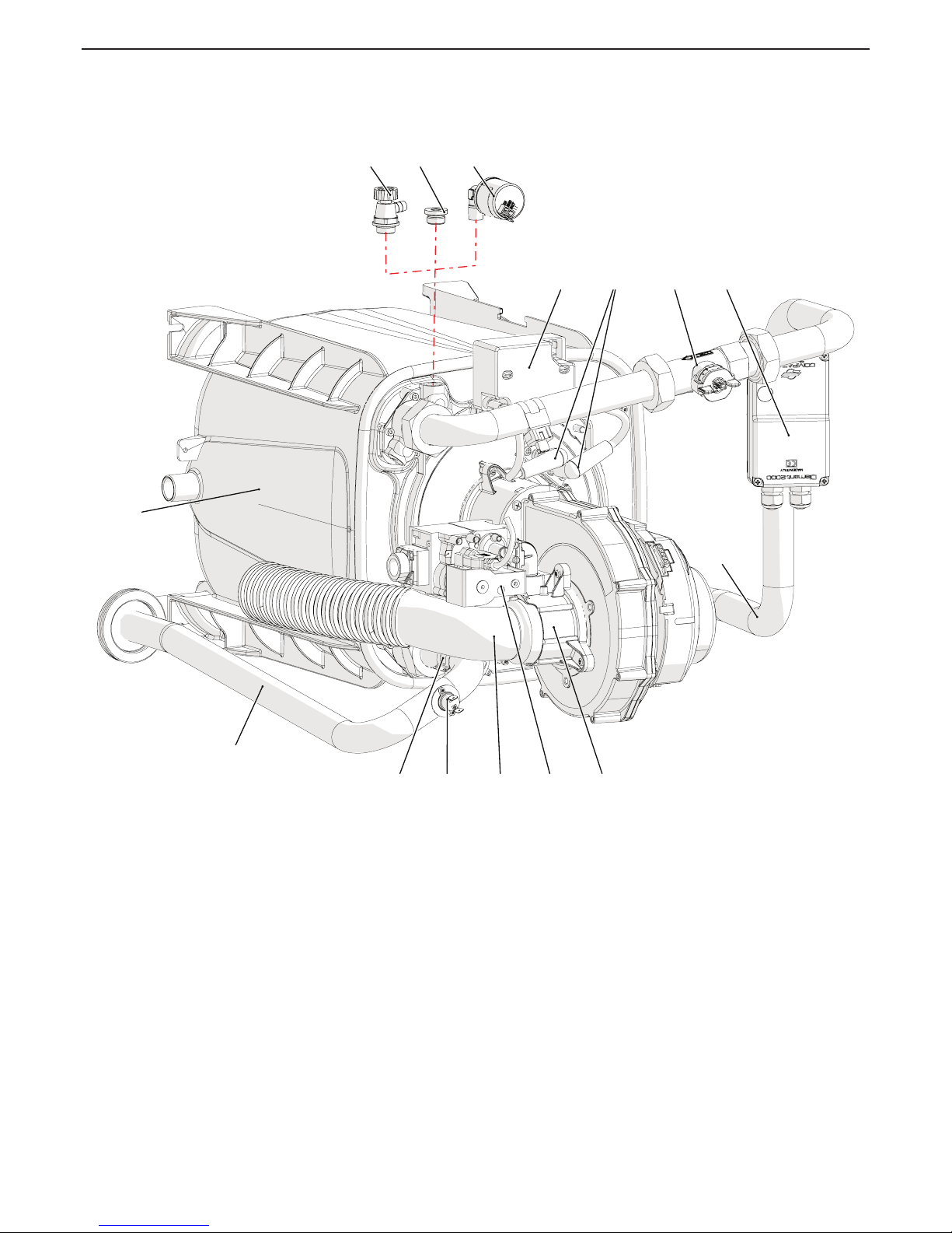
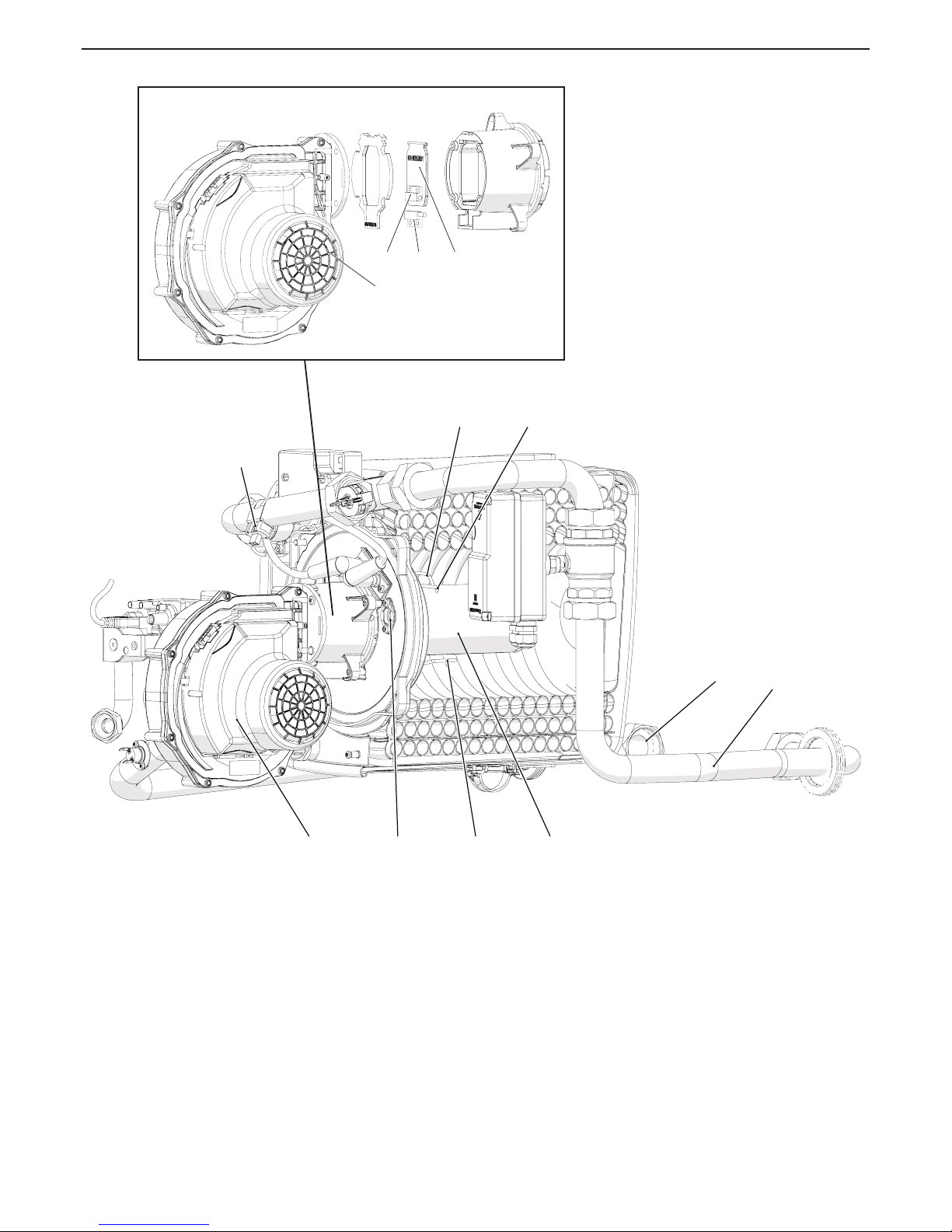
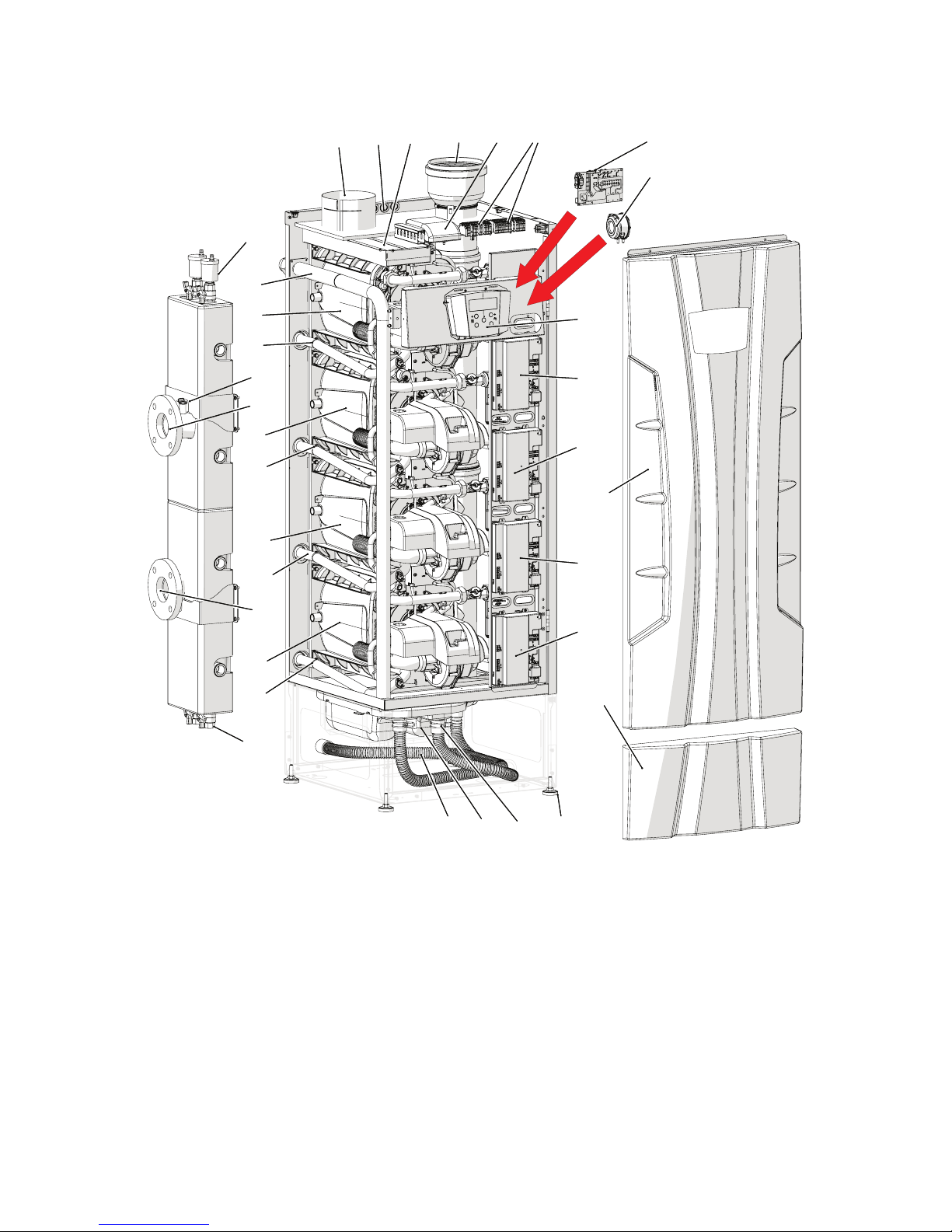
1 - Air/gas mixing unit
2 - Gas valve
3 - Air inlet manifold
4 - Hot water safety thermostat
5 - Hot water temperature probe
6 - ---------7 - Hot water supply pipe
8 - ---------9 - Heat exchanger
10 - ----------
11 - ---------12 - Plug (not present)
13 - Water pressure sensor (present on the MASTER burner 1)
14 - Spark generator
15 - Ignition cables
16 - Water ow rate measuring device
17 - Motorised 2-way valve (on request)
18 - Water inlet pipe
39 - Air bleed valve (present on all slave burners)
3 - MAIN COMPONENTS
Figure 3-1 - Components inside 60T, 70T, 100T, 115T, 140T, 180T, 210T and 280T models
18
17
9
7
15 1614
5
1239 13
134 2
020009.01.018
Page 11
11
60T - 280T
COSMOGAS
19 - Burner
20 - ---------21 - Detection electrode
22 - ---------23 - Burner warning light
24 - ---------25 - Fan
26 - Water inlet temperature sensor
27 - LH ignition electrode
28 - RH ignition electrode
29 - ---------30 - ---------31 - Flue gas check valve
32 - Check valve magnet
33 - Check valve sensor
3 - MAIN COMPONENTS
Figure 3-2 - Components inside 60T, 70T, 100T, 115T, 140T, 180T, 210T and 280T models
7
21 19
27 28
23
26
18
25
020009.01.028
32 33 31
25
020009.01.028_a
Page 12
12
60T - 280T
COSMOGAS
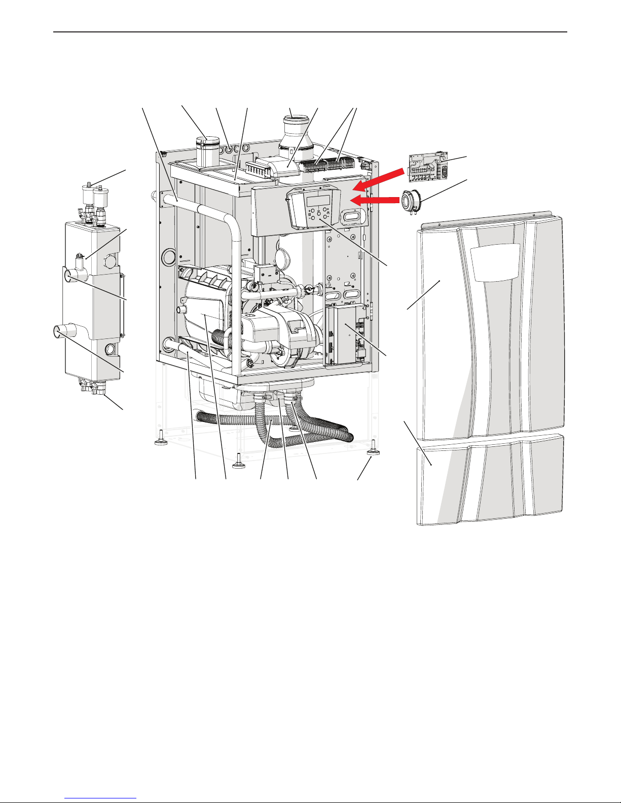
1 - Adjustable feet
2 - Flue exhaust condensate drain pipe
3 - Condensate neutraliser
4 - Burner “1” (MASTER)
5 - Condensate drain pipe
6 - Gas inlet pipe
7 - Hot water supply pipe
9 - Air intake
10 - Electrical wire passage
11 - Air intake lter
12 - Flue exhaust
13 - 885 IF board (on request)
14 - Electrical connections
15 - ---------16 - ---------17 - Control panel
19 - Upper front casing
20 - “Burner 1” command and control board
21 - Lower front casing
24 - Pressure switch against discharge clogging
25 - Wiring diagram
35 - Automatic air vent
36 - Water supply connection
37 - Water return connection
38 - Drain valves
3 - MAIN COMPONENTS
Figure 3-3 - Components inside 60T and 70T models
5
10
37
1
12
35
26
38
36
7 4
6
24
25
9
3 2
11 14
20
13
17
21
19
020014.01.023
Page 13
13
60T - 280T
COSMOGAS
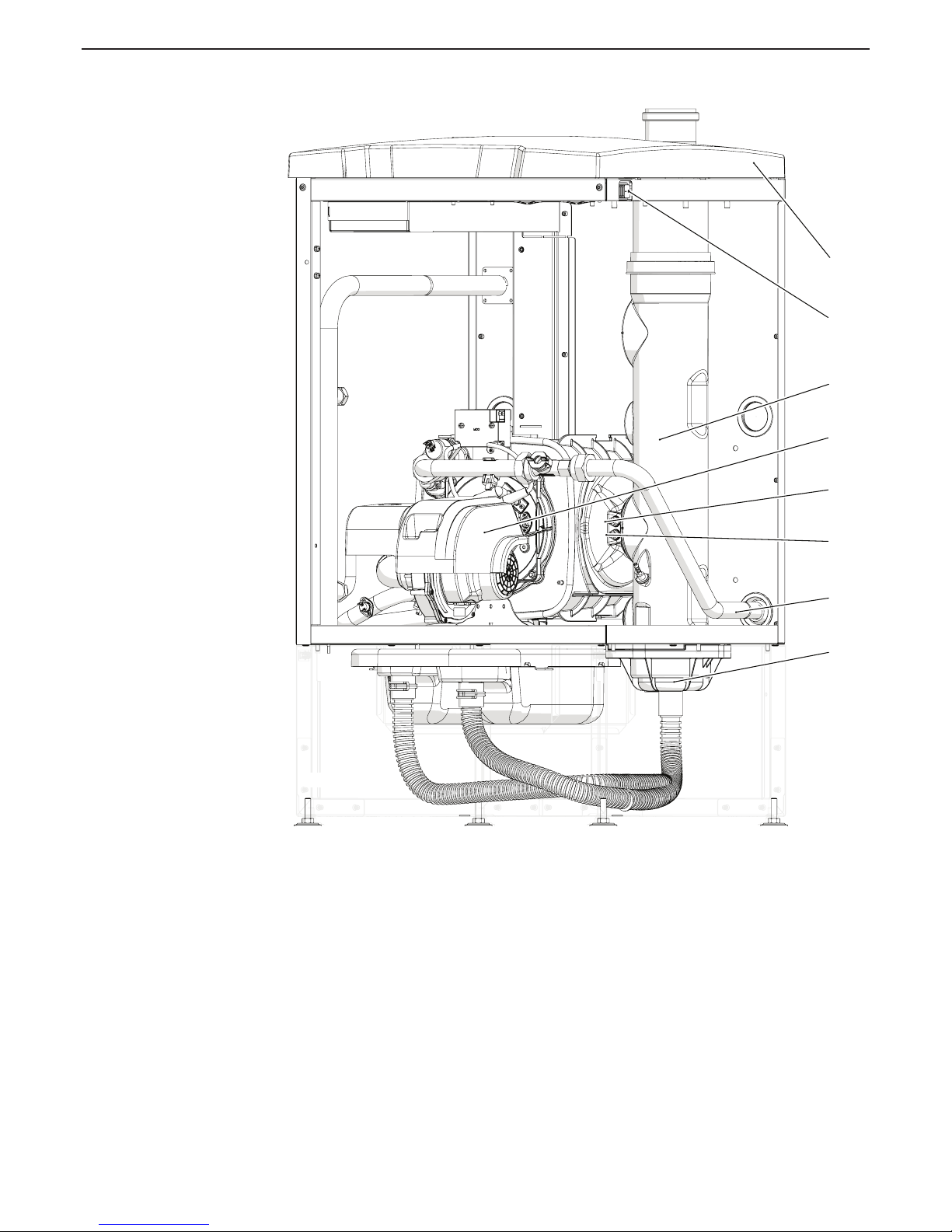
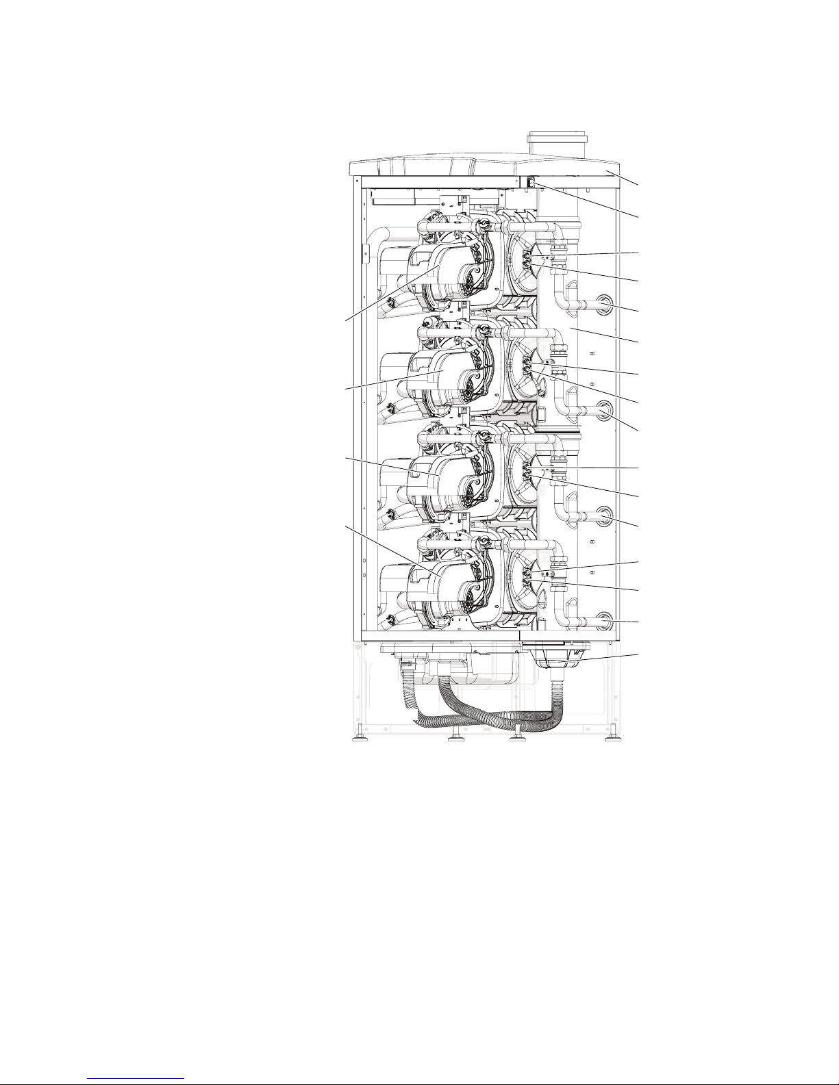
22 - Upper covering
23 - Main ON/OFF switch
27 - Fan covering
28 - Flue exhaust temperature safety fuse
29 - Flue exhaust temperature probe
30 - Flue exhaust manifold
31 - Water inlet pipe
32 - ---------33 - Condensate level sensor
34 - ----------
3 - MAIN COMPONENTS
Figure 3-4 - Components inside 60T and 70T models
31
22
33
30
28
29
27
23
020014.01.024
Page 14

14
60T - 280T
COSMOGAS
1 - Adjustable feet
2 - Flue exhaust condensate drain pipe
3 - Condensate neutraliser
4 - Burner “1” (MASTER)
5 - Condensate drain pipe
6 - Gas inlet pipe
7 - Hot water supply pipe
8 - Burner “2” (SLAVE)
9 - Air intake
10 - Electrical wire passage
11 - Air intake lter
12 - Flue exhaust
13 - 885 IF board (on request)
14 - Electrical connections
15 - ---------16 - ---------17 - Control panel
18 - “Burner 2” command and control board
19 - Upper front casing
20 - “Burner 1” command and control board
21 - Lower front casing
24 - Pressure switch against discharge clogging
25 - Wiring diagram
26 - Water outlet manifold temperature sensor
35 - Air bleed valve
36 - Water outlet
37 - Water inlet
38 - Drain cock
3 - MAIN COMPONENTS
Figure 3-5 - Components inside 100T, 115T and 140T models
5
10
37
12
1
35
26
38
7
36
4
6
24
25
98
3 2
11 14
20
18
13
17
21
19
5
10
37
12
1
35
26
38
7
36
4
6
24
25
98
3 2
11 14
20
18
13
17
21
19
020014.01.003
Page 15
15
60T - 280T
COSMOGAS
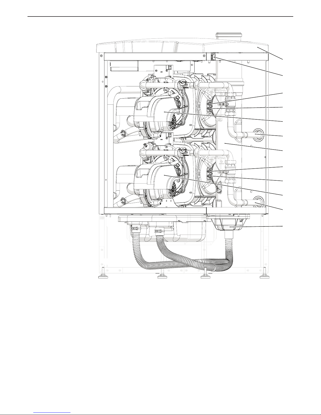
22 - Upper covering
23 - Main ON/OFF switch
26 - Water general outlet temperature sensor
27 - Fan covering
28 - Flue exhaust temperature safety fuse
29 - Flue exhaust temperature probe
30 - Flue exhaust manifold
31 - Water inlet pipe
32 - ---------33 - Condensate level sensor
34 - ----------
3 - MAIN COMPONENTS
Figure 3-6 - Components inside 100T, 115T and 140T models
31
31
22
33
30
28
28
29
29
27
27
23
31
31
22
33
30
28
28
29
29
27
27
23
020014.01.004
BURNER 2
BURNER 1
(Master)
Page 16
16
60T - 280T
COSMOGAS
3 - MAIN COMPONENTS
Figure 3-7 - Components inside 180T, 210T and 280T models
25
5
7
10
38
21
7
12
8
37
7
26
8
24
7
3
19
36
9
4
2
6
35
8
18
18
11
20
1
14
18
13
17
25
5
7
10
38
21
7
12
8
37
7
26
8
24
7
3
19
36
9
4
2
6
35
8
18
18
11
20
1
14
18
13
17
020013.01.001
1 - Adjustable feet
2 - Flue exhaust condensate drain pipe
3 - Condensate neutraliser
4 - Burner “1” (MASTER)
5 - Condensate drain pipe
6 - Gas inlet pipe
7 - Hot water supply pipe
8 - Burner “2”-”3”-”4” (SLAVE)
9 - Air intake
10 - Electrical wire passage
11 - Air intake lter
12 - Flue exhaust
13 - 885 IF board (on request)
14 - Electrical connections
15 - ---------16 - ---------17 - Control panel
18 - Burner “2”-”3”-”4” command and control board
19 - Upper front casing
20 - Burner “1” command and control board
21 - Lower front casing
24 - Pressure switch against discharge clogging
25 - Wiring diagram
26 - Water outlet manifold temperature sensor
35 - Air bleed valve
36 - Water outlet
37 - Water inlet
38 - Drain cock
Page 17
17
60T - 280T
COSMOGAS
3 - MAIN COMPONENTS
Figure 3-8 - Components inside 180T, 210T and 280T models
31
31
31
31
22
28
29
28
33
28
29
30
28
29
29
27
27
27
27
23
31
31
31
31
22
28
29
28
33
28
29
30
28
29
29
27
27
27
27
23
020013.01.010
BURNER 2
(Not present on 180T
and 210T models)
BURNER 1
(Master)
BURNER 3
BURNER 4
22 - Upper covering
23 - Main ON/OFF switch
27 - Fan covering
28 - Flue exhaust temperature safety fuse
29 - Flue exhaust temperature probe
30 - Flue exhaust manifold
31 - Water inlet pipe
32 - ---------33 - Condensate level sensor
34 - ----------
Page 18
18
60T - 280T
COSMOGAS
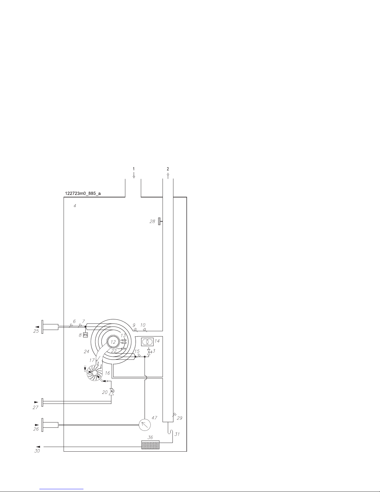
4 - OPERATION
Figure 4-1 key:
1 - Air intake
2 - Flue exhaust
3 - Air bleed valve
4 - Sealed chamber
6 - Water outlet temperature safety thermostat
7 - Water outlet temperature sensor
8 - Water pressure measuring device
9 - Flue exhaust temperature probe
10 - Flue exhaust temperature safety fuse
12 - Pre-mixed burner
13 - Ignition electrodes
14 - Spark generator
15 - Water inlet temperature sensor
16 - Fan
17 - Flue gas non-return valve
20 - Gas valve
22 - Detection electrode
24 - CRV Heat exchanger
25 - Water outlet
26 - Water inlet
27 - Gas inlet
28 - Pressure switch against discharge clogging
29 - Condensate level sensor
30 - Condensate drain
31 - Condensate drain siphon
36 - Condensate neutraliser
47 - Water ow rate measuring device
Figure 4-1 - 60T and 70T model functional hydraulic diagram
Page 19
19
60T - 280T
COSMOGAS
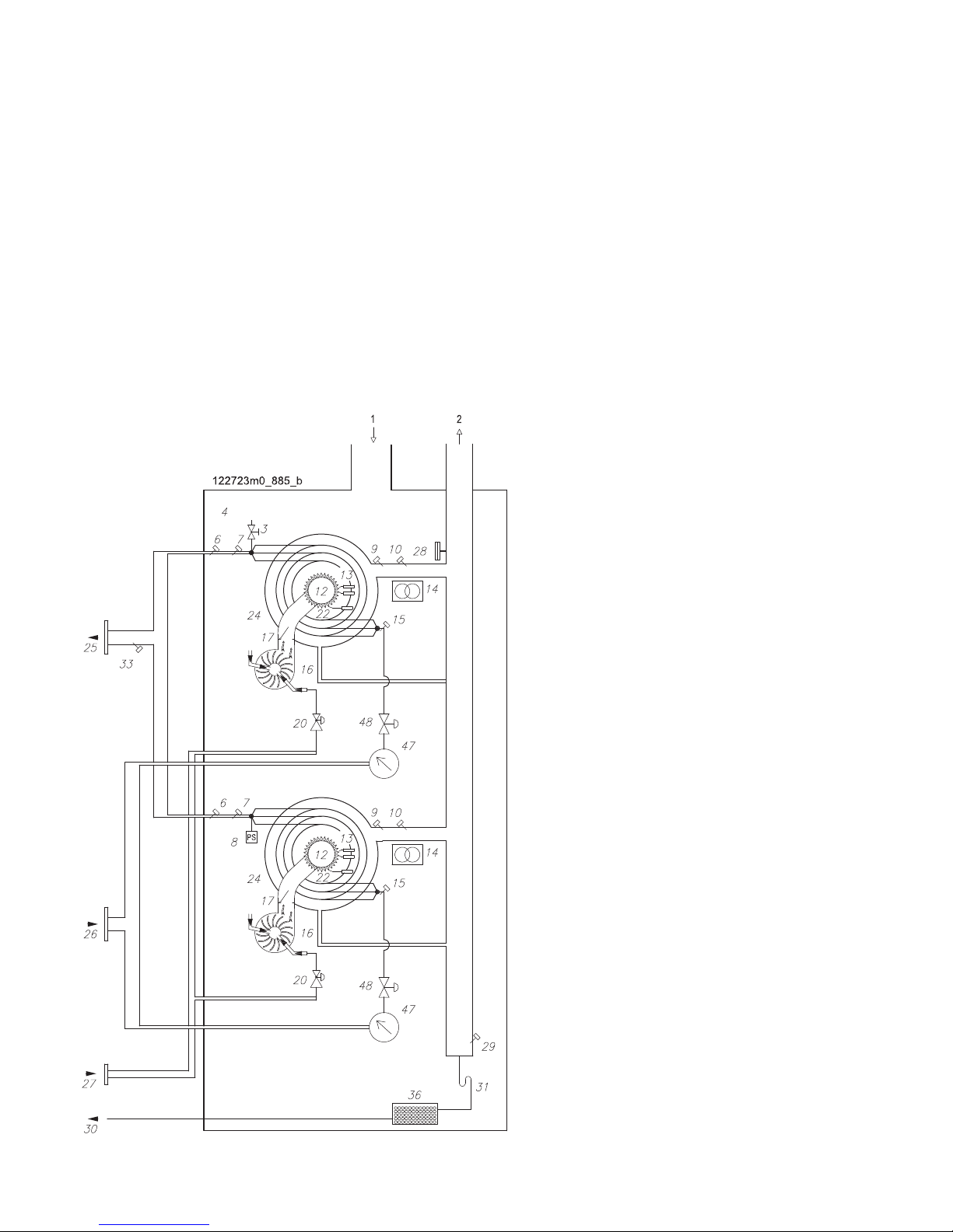
4 - OPERATION
Figure 4-2 - 100T, 115T and 140T model functional hydraulic diagram
Figure 4-2 key:
1 - Air intake
2 - Flue exhaust
3 - Air bleed valve
4 - Sealed chamber
6 - Water outlet temperature safety thermostat
7 - Water outlet temperature sensor
8 - Water pressure measuring device
9 - Flue exhaust temperature probe
10 - Flue exhaust temperature safety fuse
12 - Pre-mixed burner
13 - Ignition electrodes
14 - Spark generator
15 - Water inlet temperature sensor
16 - Fan
17 - Flue gas non-return valve
20 - Gas valve
22 - Detection electrode
24 - CRV Heat exchanger
25 - Water outlet
26 - Water inlet
27 - Gas inlet
28 - Pressure switch against discharge clogging
29 - Condensate level sensor
30 - Condensate drain
31 - Condensate drain siphon
33 - Manifold outlet temperature sensor
36 - Condensate neutraliser
47 - Water ow rate measuring device
48 - Motorised 2-way valve (on request)
Page 20
20
60T - 280T
COSMOGAS
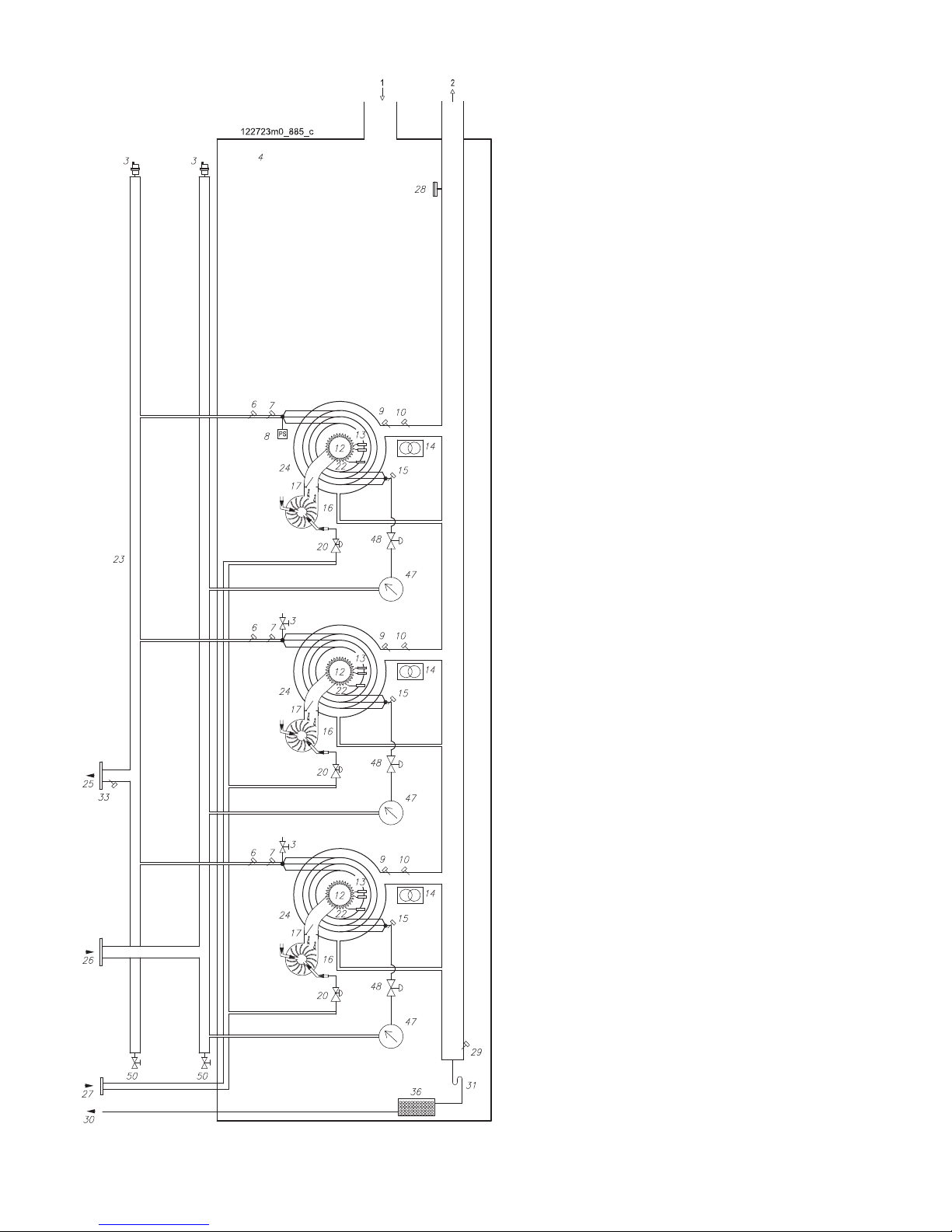
4 - OPERATION
Figure 4-3 - 180T, 210T model functional hydraulic diagram
Figure 4-3 key:
1 - Air intake
2 - Flue exhaust
3 - Air bleed valve
4 - Sealed chamber
6 - Water outlet temperature safety thermostat
7 - Water outlet temperature sensor
8 - Water pressure measuring device
9 - Flue exhaust temperature probe
10 - Flue exhaust temperature safety fuse
12 - Pre-mixed burner
13 - Ignition electrodes
14 - Spark generator
15 - Water inlet temperature sensor
16 - Fan
17 - Flue gas non-return valve
20 - Gas valve
22 - Detection electrode
23 - Inlet and outlet manifold
24 - CRV Heat exchanger
25 - Water outlet
26 - Water inlet
27 - Gas inlet
28 - Pressure switch against discharge clogging
29 - Condensate level sensor
30 - Condensate drain
31 - Condensate drain siphon
33 - Manifold outlet temperature sensor
36 - Condensate neutraliser
47 - Water ow rate measuring device
48 - Motorised 2-way valve (on request)
50 - Drain cocks
Page 21
21
60T - 280T
COSMOGAS
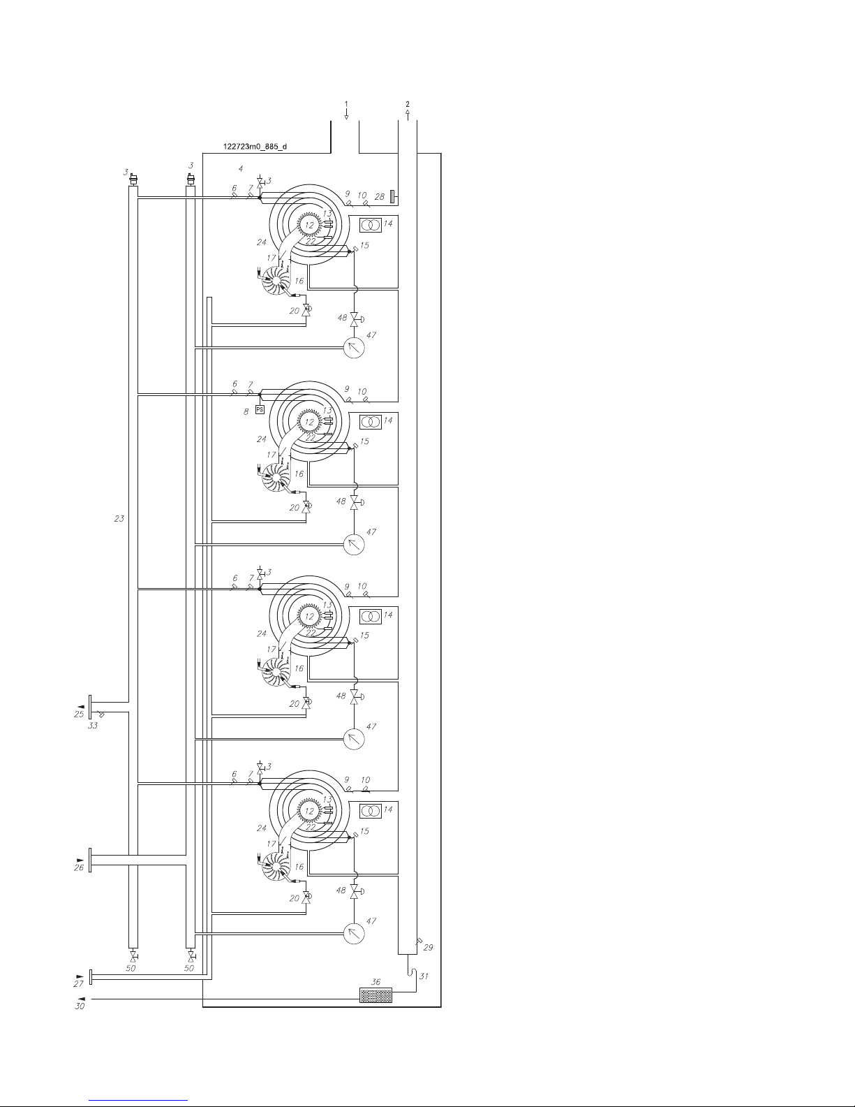
4 - OPERATION
Figure 4-4 - 280T model functional hydraulic diagram
Figure 4-4 key:
1 - Air intake
2 - Flue exhaust
3 - Air bleed valve
4 - Sealed chamber
6 - Water outlet temperature safety thermostat
7 - Water outlet temperature sensor
8 - Water pressure measuring device
9 - Flue exhaust temperature probe
10 - Flue exhaust temperature safety fuse
12 - Pre-mixed burner
13 - Ignition electrodes
14 - Spark generator
15 - Water inlet temperature sensor
16 - Fan
17 - Flue gas non-return valve
20 - Gas valve
22 - Detection electrode
23 - Inlet and outlet manifold
24 - CRV Heat exchanger
25 - Water outlet
26 - Water inlet
27 - Gas inlet
28 - Pressure switch against discharge clogging
29 - Condensate level sensor
30 - Condensate drain
31 - Condensate drain siphon
33 - Manifold outlet temperature sensor
36 - Condensate neutraliser
47 - Water ow rate measuring device
48 - Motorised 2-way valve (on request)
50 - Drain cocks
Page 22

22
60T - 280T
COSMOGAS
4.1 - Operation and intended use
4.1.1 - Boiler operation and intended use
This is a gas condensing appliance intended to generate
centralised heating. It can also be used for domestic hot
water production for civil use, but it must be appropriately
connected to a storage tank (see g. 10-2). Any other use is
prohibited.
Maximum domestic hot water service output heat is always
guaranteed as the appliance give priority to said service.
Follow the procedure described in section 16.6 to adjust the
domestic hot water temperature.
The heating system can be created with heat elements that
work at a temperature range from 30°C to 80°C.
The boiler can be connected to a room thermostat, an
external probe or a 0-10Vdc analogue input.
This boiler must be connected to a heating and domestic
hot water production system with required output heat that
is compatible with the features of the appliance itself.
Figure 4-5 - 280T model appliance modulation
4.1.2 - Wide range of modulation and
maximum performance
The appliance management program, depending on the head
required by
the system, provides for the
gradual ignition of
each single heating element at minimum output (see figure
4-5). After which, if the head required by the system
increases, all the heating elements progressively increase
output. This achieves modulated output heat that goes from
a minimum of 14kW to a maximum corresponding to the
architecture of the appliance (figure 4-5 shows a 280T
module with 4 heating elements), with maximum efficiency
consequently maintained for the entire modulation range.
When the boiler is connected to an external probe, it always
works at maximum output (see section 16.9).
4 - OPERATION
Page 23
23
60T - 280T
COSMOGAS
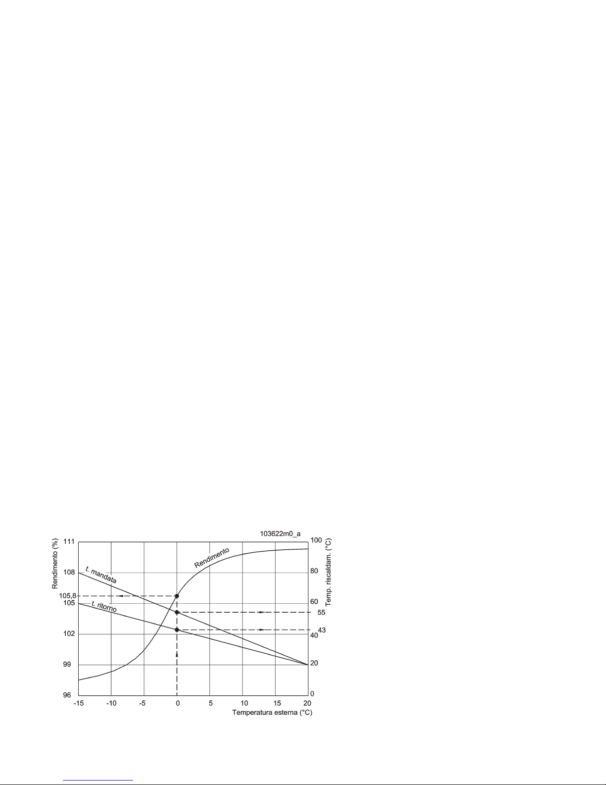
Figure 4-6 - Example of output diagram / supply and return temperature / external temperature, for a
home in a very cold area and radiator system.
4.1.7 - Boiler domestic hot water
production
A storage tank must be connected for domestic hot water
production following the diagram referred to in
gure 10-2.
The domestic hot water temperature is adjusted following the
specific procedure in section 16.6.
4.1.8 - System types
The following types of systems can be created with this
appliance:
- Only centralised heating system (see gure 10-1)
- Only domestic hot water production system (see gure 11-1)
- Centralised heating and domestic hot water production
system (see gure 10-2).
4.2 - Precautions when installing
For proper appliance operation, respect the following
instructions:
It must be connected to a heating system and, if necessary,
to a domestic hot water distribution mains, compatibly with
the features, performance and output of the appliance itself.
Check gures 7-1 and 7-2 regarding the minimum distances
to respect for installation and future maintenance.
4.3 - Anti-legionella
Boiler (when connected to a
storage tank) have no antilegionella protection:
It is the installer’s responsibility to keep the storage tank
temperature no lower than 60°C to disinfect it or adopt
equivalent systems.
4 - OPERATION
This system allows the supply temperature to be managed
automatically based on the ex ter nal tem per ature. An
operating example is shown as a graphic in gure 4-6. The
graphic shows an example in which the supply and return
temperatures are 55°C and 43°C respectively and the
external temperature is 0°C. The external probe controls boiler
modulation, progressively reducing the supply temperature
and optimising output. Output changes from 97% when the
external temperature is -15°C to 105,8% with 0°C external
temperature and up to 109° with 20°C external temperature.
4.1.3 - Main circuit pump
T
he appliance is specically built without an inner pump
to give installers the option of connecting it to any pump,
even a modulating one. The main circuit pump is part “36”
in gures 10-1 and 10-2. To choose this pump, the designer
must check what is described in section 10.11 as well as the
system features.
4.1.4 - Heating circuit pump
The heating circuit pump, part “19” in gures 10-1 and 10-2,
is not supplied to give the installer the option of connecting it
to any pump, even a modulating one. To choose this pump,
the designer must check the system features.
4.1.5 - Domestic hot water circuit pump
The domestic hot water circuit pump, part “28” in gure 10-2
and part “36” in gure 11-1, is not supplied to give the installer
the option of connecting it to any pump, even a modulating
one. To choose this pump, the designer must check the
system features.
4.1.6 - Hydraulic separator
If the system needs to be served by a higher water ow rate
than what the pump is able to dispense, a hydraulic separator
must be put between the boiler and the system (see gures
10-1 and 10-2, part “20”).
Page 24
24
60T - 280T
COSMOGAS
C
B
A
020010.01.011
D
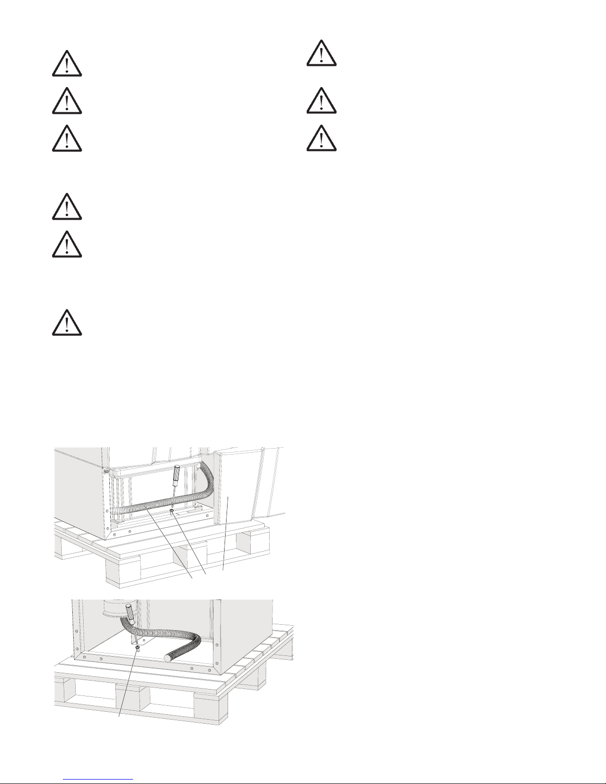
020010.01.012
Figure 5-1 - Disassembling transport pallet screws
5.1 - Choosing the installation site
ATTENTION !!! Do not store any ammable
material in the immediate vicinity of the appliance.
ATTENTION !!! Do not install the appliance on
carpeting.
ATTENTION !!! The appliance must be installed
in a room in which it can be supplied with air for
ventilation and combustion, whether that air is taken
from the outside (sealed combustion) or the inside
(combustion in ventilated chamber).
ATTENTION !!! Insufcient appliance ventilation
can cause high air temperatures.
ATTENTION !!! Make sure the intake and
exhaust openings are appropriately sized and that
there are no obstructions or clogs. If the problem is not
resolved, do not start the appliance. Please keep these
restrictions in mind, as well as the dangers they can
present to the operator.
ATTENTION !!! LP gas Liqueed Petroleum
gas - Installation requires special attention: LP gas
appliances must not be installed in pits, cellars or
similar locations where the gas, which is heavier than
air, could stagnate. Appliances with this kind of fuel
must not be installed in spaces under the level of the
oor or cellars. Failure to respect this precaution could
cause explosions and serious harm to people, death or
enormous material damage.
5 - INSTALLATION - Installation site
ATTENTION !!! Installing the appliance in rooms
with thin oors could create resonance noise. Install
elements that reduce the noise.
ATTENTION !!! Do not allow to much dust to
accumulate on the appliance.
ATTENTION !!! The appliance must only be
installed on solid ooring that supports the weight and
is level.
Before installing, wash the heating system and, if
necessary, the domestic hot water system thoroughly
in order to remove any residues or impurities that could
compromise proper appliance operation.
This appliance is not made to be installed in the open.
It must not be exposed to temperatures below zero or
above 50°C. Choose a location inside the home or, in
any case, sheltered from elements like rain, wind, sun
and, especially, frost.
This device must be installed in this sort of location so
that any water leaks coming from it, from the connections
between the pipes or from potential safety valve drainage
cannot damage materials or things underneath it.
Establish the appropriate room and position for installation,
keeping the following factors in mind:
- ue exhaust/air intake duct connection;
- gas adduction duct connection;
- water supply connection;
- centralised heating system connection;
- domestic hot water system connection (if present);
- electrical connection;
- connection of the condensate drain generated by the
boiler;
- room thermostat electrical connection;
- safety valve discharge connection;
- any external temperature sensor connection;
- room ventilation.
Page 25

25
60T - 280T
COSMOGAS
Figure 5-2 Example of ventilation with methane
gas appliance
Figure 5-3 Example of ventilation with LP gas
appliance
CENTRAL
HEATING UNIT
VENTILATION
OPENING
METHANE
GAS
APPLIANCE
5.1.1 Requirements for proper ventilation
The utility room MUST have a properly sized ventilation opening.
To ensure proper ventilation for combustion in compliance with
the national and local standards in force, abide by the following:
At least one direct opening to the outside is required for
combustion, which must have a minimum area of 3000 cm2 of
5000 cm2 if the appliance runs on LP gas. Said opening must
be positioned less than 30 cm from the ceiling if the appliance
runs on METHANE gas (see g 5-2) or along the oor if it runs
on LP gas (see g 5-3).
The openings must communicate directly with the outside. The
requisites described above refer to one appliance; in rooms
where there are several appliances, greater free oor space is
required to provide adequate ventilation for the combustion of
all the appliances.
ATTENTION !!!
In no case must the central
heating unit be in a negative pressure state. Therefore,
consider the presence of any discharge fans, ceiling fans,
dryers, compressors, air heating units, etc. that can take
air away from the appliance.
ATTENTION !!!
EXTRACTORS: Extractors or
similar devices to discharge air from the central heating
unit can decrease the ventilation required for combustion
and/or cause vacuums in the ventilation system. Flue
exhaust leaks from the ventilation system in an inhabited
room can cause very dangerous conditions that must be
corrected immediately.
5.1.2 - Preventing combustion air
contamination
Do not position air intake and/or ue exhaust outlets in rooms
where combustion air can be contaminated.
ATTENTION !!! Contaminated combustion air
can damage the appliance
.
Make sure the combustion air does not contain any of the
following contaminating agents.
Products that can contaminate combustion air:
- Permanent wave solutions;
- Chlorinated waxes/cleaning products;
- Chlorine-based pool chemical products;
- Calcium chloride used for defrosting;
- Sodium chloride used to soften water;
- Coolant leaks;
- Solutions to remove paint or varnish;
- Hydrochloric acid/muratic acid;
- Cements and adhesives;
- Antistatic softeners used in dryers;
- Chloro-type bleaches, detergents and cleaning solvents
found in laundry rooms for home use;
- Adhesives used to secure construction products and other
similar products;
CENTRAL
HEATING UNIT
VENTILATION
OPENING
LP
GAS
APPLIANCE
5 - INSTALLATION - Installation site
Page 26
26
60T - 280T
COSMOGAS
Figure 6-2 - Levelling feet
Figure 6-1 - Lifting system
6 - INSTALLATION - Setup
6.1 - Setup
To correctly and easily install the appliance, the following steps
must be followed scrupulously.
6.1.1 - Moving the appliance
ATTENTION !!! Use appropriate forklifts for the
type of appliance to move it. Failure to respect this
could cause enormous damages.
Position the appliance in the area chosen for installation,
handling it with the pallet on which it is secured, making sure
to keep it upright without making any sudden movements that
could cause it to overturn.
To free the appliance from the pallet, unscrew the front (part
“C” in gure 5-1) and rear (part “D” in gure 5-1) xing screws.
6.1.2 - Opening the package
The appliance is supplied in cardboard packaging secured to a
pallet for transport. Be careful when opening, lift the cardboard
box upwards after having detached it from the pallet.
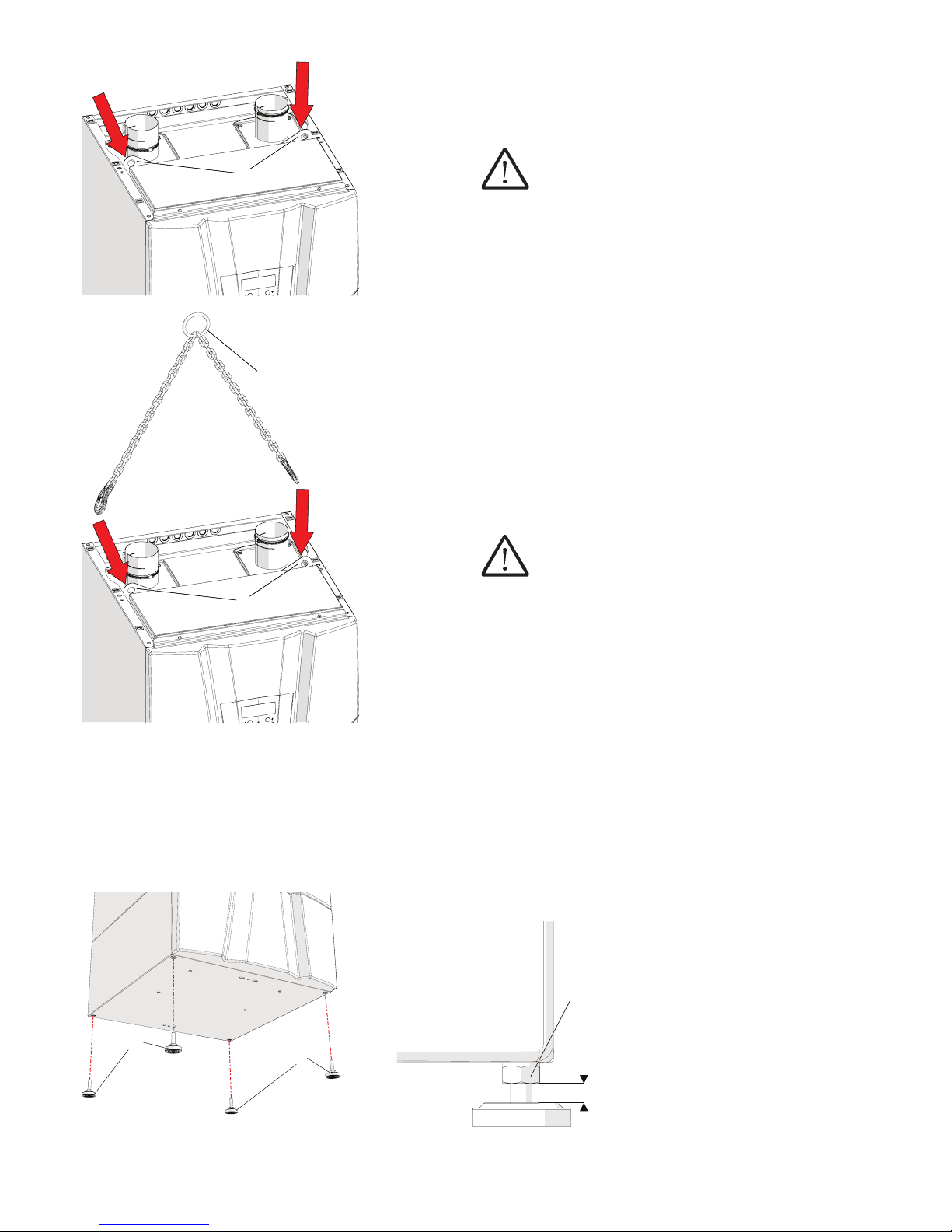
6.1.3 - Lifting the appliance
There is a bracket (part “A” in gure 6-1) to facilitate installation
that allows the appliance to be lifted.
remove the upper covering as per section 17.2;
hook the lifting cables, “B” in gure 6-1, to the bracket, “A”
in gure 6-1, and lift the heating module;
ATTENTION !!! The lifting cables and system
must be suitable to the purpose. In particular, they
must resist the weight of the appliance, which you can
check in section 18.
install the adjustable feet “A” to level the appliance as per
gure 6-2.
Once the appliance has been positioned properly, the lifting
cables (part “B” in gure 6-1) must be removed before applying
the upper covering.
A
A
020010.01.013
B
MIN 0
MAX 0,39 " (10 mm)
020010_01_030
B = Locking nut
AA
020021.01.009
BAB
A
020021.01.010
Page 27

27
60T - 280T
COSMOGAS
7 - INSTALLATION - Minimum distances to respect
7.1 - Dimensions and minimum
distances to respect
Free space must be left around the appliance both for
installation and maintenance, as illustrated in gures 7-1
and 7-2. Figures 8-1, 8-2, 9-1 and 9-2 show the appliance
connection dimensions and centre distances.
Figure 7-1 - Minimum distances to respect for 60T, 70T, 100T, 115T and 140T models
Figure 7-2 - Minimum distances to respect for 180T, 210T and 280T models
Page 28
28
60T - 280T
COSMOGAS
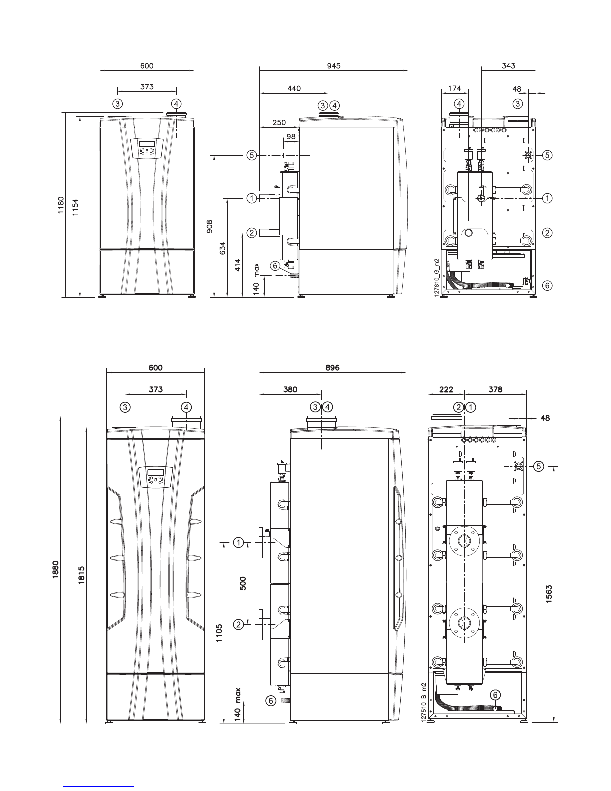
8 - INSTALLATION - Dimensions and centre distances - Boiler
Figure 8-1 - Fitting dimensions and centre distances for 60T, 70T, 100T, 115T and 140T
models (References in figure 9-1)
Figure 8-2 - Fitting dimensions and centre distances for 180T, 210T and 280T models (References in figure 9-1)
Page 29
29
60T - 280T
COSMOGAS
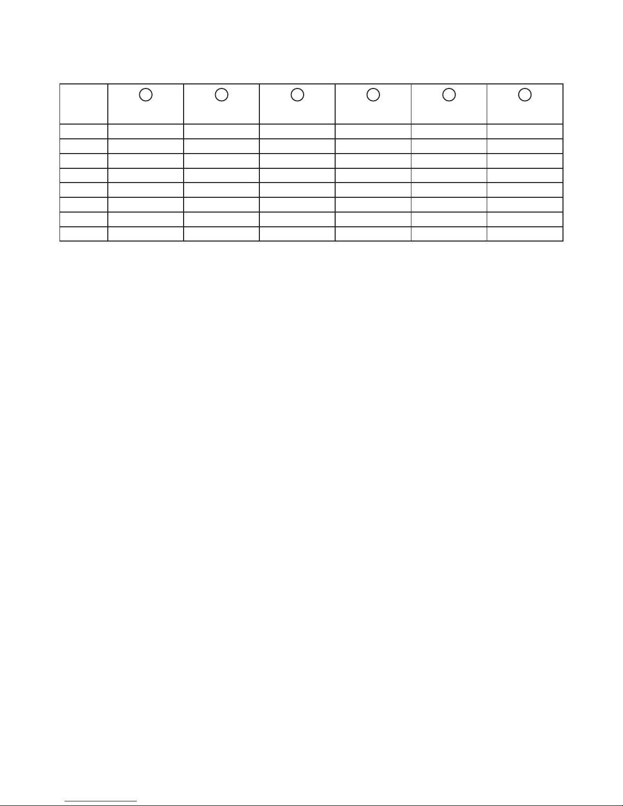
9 - INSTALLATION - Dimensions and centre distances table - Boiler
MODEL
1
SUPPLY
2
RETURN
3
AIR INTAKE4FLUE EXHAUST
5
GAS
6
CONDENSATE
DRAIN
60T 1”1/2 1”1/2 80 mm 80 mm 1” 28mm
70T 1”1/2 1”1/2 80 mm 80 mm 1” 28mm
100T 1”1/2 * 1”1/2 * 110 mm 110 mm 1” 28mm
115T 1”1/2 * 1”1/2 * 110 mm 110 mm 1” 28mm
140T 1”1/2 * 1”1/2 * 110 mm 110 mm 1” 28mm
180T DN65 PN16 * DN65 PN16 * 160 mm 160 mm 1”1/4 28mm
210T DN65 PN16 * DN65 PN16 * 160 mm 160 mm 1”1/4 28mm
280T DN65 PN16 * DN65 PN16 * 160 mm 160 mm 1”1/4 28mm
* Fittings and anges are not factory assembled
Figure 9-
1 - Figure 8-1 and 8-2 connection diameter table
Page 30

30
60T - 280T
COSMOGAS
10 - INSTALLATION - Hydraulic connections - boiler
10.1 - Boiler gas and
hydraulic connections
ATTENTION !!! Before installing, wash the
heating system and, if necessary, the domestic hot
water system thoroughly in order to remove any
residues or impurities that could compromise proper
appliance operation.
To identify the position of the ttings, see gures 8-1 and 8-2.
Gas connection
The gas connection must be done at the corresponding
tting with a rigid metal pipe. The gas counter ow rate must
be sufcient for simultaneous use of all the gas appliances
connected to it. Connect the gas to the appliance according to
the standards in force. The diameter of the gas pipe coming
out of the generator does not determine the choice of the
diameter of the pipe between the appliance and the counter;
the latter must be chosen based on its length and head loss.
ATTENTION !!! Remember to install a gas shut-
off valve right before the appliance in order to be able
to shut off the gas supply.
ATTENTION !!! Supplying the boiler with
a different type of gas than those provided for is
prohibited.
10.2 - Boiler safety valve
(installer’s responsibility)
The appliance is supplied without an overpressure safety
valve to all the installer to choose the appropriate valve for
the system service pressure (check appliance operation
pressure in the technical features). Installation must be
done so as to allow the user to check valve intervention,
should it open. The safety valve drain (the installer’s
responsibility) must then be directed in order to avoid
danger for people in the event it intervenes.
ATTENTION !!! If the safety valve is not directed,
it could harm persons, animals or objects should it
intervene.
10.3 - Examples of boiler installations
Figure 10-1 - Example of boiler connection diagram
Figure 10-1 KEY
1 Boiler 60T-280T model boiler
2 INAIL safety valve
3 INAIL manometer
4 INAIL thermometer
5 INAIL maximum safety pressure switch
6 INAIL safety thermostat
7 Gas cock
8 INAIL gas shut-off valve
9 INAIL well
10 Gas inlet
11 Expansion tank
12 Micro-bubble separator
13 External probe
14 Filter
15 Electrical power supply
16 Low or high temperature heating system
17 System loading unit
18 Domestic cold water
19 Heating circuit pump
20 - Hydraulic separator
21 Air bleed valve
23 ---------24 INAIL minimum safety pressure switch
36 Main circuit pump
37 Room thermostat or equivalent system
56 Balancing valve (necessary if there is a motorised valve,
part “17” in gure 3-1, on the appliance and the pump, “36”,
is NOT the modulating type)
57 Drain cock (Mandatory in the 60, 70, 100, 115, 140 models )
58 Manifold sensor
Page 31

31
60T - 280T
COSMOGAS
1 Boiler 60T-280T series appliance
2 INAIL safety valve
3 INAIL manometer
4 INAIL thermometer
5 INAIL safety maximum pressure switch
6 INAIL safety thermostat
7 Gas cock
8 INAIL gas shut-off valve
9 INAIL well
10 Gas inlet
11 Expansion tank
12 Micro-bubble separator
13 External probe
14 Filter
15 Electrical power supply
16 ----------
17 Air bleed valve
18 Domestic cold water
19 Heating circuit pump
20 - Hydraulic separator
21 Shut-off valve
22 Check valve
23 Heating system supply
Figure 10-2 - Example of
boiler connection diagram
with hydraulic separator and
storage tank
24 Heating system return
25 Plug for sludge drain
26 Heating system mixing valve
27 System drain
28 Storage tank loading pump
29 System loading unit
30 Storage tank safety valve
31 Hot water tank temperature sensor
32 Domestic circuit expansion tank
33 Domestic hot water supply
34 INAIL safety minimum pressure switch
36 Main circuit pump
37 Room thermostat or equivalent system
56 Balancing valve (necessary if there is a motorised valve, part
“17” in Figure 3-1, on the appliance and the pump, “36”, is NOT the
modulating type)
57 Drain cock (Mandatory in the 60, 70, 100, 115, 140 models )
58 Manifold sensor
10 - INSTALLATION - Hydraulic connections - boiler
Page 32

32
60T - 280T
COSMOGAS
Figure 10-3 - 60T to 140T INAIL KIT
Figure 10-4 - 180T to 280T INAIL KIT
12
16
7
11
3
86 8
4
5
21
12
13
15
14
12
16
7
11
3
86 8
4
5
21
12
13
15
14
020014.01.011
13
6
10
14
2
16
1
11
12
7
5
4
15
1
2
3
020014.01.012
10.4 - Boiler INAIL safety devices
The appliance comes standard supplied without the INAIL
safety devices.
ATTENTION !!! All appliances over 35 kW of
output heat must, under the installer’s responsibility,
be equipped with safety devices as provided by Rule
“R” issued by the National Institute for Insurance
against Accidents at Work (INAIL).
ATTENTION !!! Installing shut-off elements
between the appliance and the safety valve (part “7” in
g. 10-3 and “15” in gure 10-4) is prohibited.
To facilitate installation, COSMOGAS provides,on request,
INAIL kits complete with the required devices and a special
pipe to install them.
Figure 10-3 shows the kit for the 60T, 70T, 100T, 115T and
140T models.
Figure 10-3 key
1 = Nipple
2 = Gasket
3 = Manifold
4 = Well for Valve probe “11”
5 = INAIL thermometer
6 = INAIL manometer
7 = INAIL safety valve
8 = Connection unit
11 = INAIL gas shut-off valve
12 = Inspection well
13 = INAIL safety thermostat
14 = INAIL safety pressure switch
15 = INAIL safety pressure switch
16 - Expansion tank connection tting
ATTENTION !!! The valve sensor “11” (gure 10-
3) goes into the probe carrier well “4” and secured with
the specic anti-slip locking screw.
Figure 10-4 shows the kit for the 180T, 210T and 280T
models
Figure 10-4 key
1 = Fixing nuts and bolts
2 = Gasket
3 = INAIL safety pressure switch
4 = INAIL safety pressure switch
5 = Connection unit
6 = INAIL safety thermostat
7 = Manifold
10 = INAIL gas shut-off valve
11 = Well for Valve probe “10”
12 = Inspection well
13 - Expansion tank connection tting
14 = INAIL manometer
15 = INAIL safety valve
16 = INAIL thermometer
ATTENTION !!! The valve sensor “10” (gure
10-4) goes into the probe carrier well “11” and secured
with the specic anti-slip locking screw.
10 - INSTALLATION - Hydraulic connections - boiler
Page 33

33
60T - 280T
COSMOGAS
10.5 - Expansion tank connection
ATTENTION !!! The appliance does not have
an expansion tank. Provide the system with an
appropriately sized expansion tank as required by the
national and local installation standards.
10.6 - Supply and return
ATTENTION !!! COSMOGAS is not liable for any
damage caused by incorrect use of additives in the
heating system.
ATTENTION !!! The system downstream of
the appliance must be built with materials that resist
temperatures up to 97°C and 11 bar of pressure.
Otherwise (i.e. plastic piping), the system must be
equipped with appropriate protection and safety
devices.
Before making the hydraulic connections, wash the system
thoroughly to remove any slag (hemp, radiator foundry
sands, etc.) that could damage the appliance. The system
must also be washed if an appliance is replaced.
You can check the positioning of the supply and return
ttings in gures 8-1 and 8-2.
Install a metal mesh lter with a 1 mm
2
opening on the
return pipe in order to stop any system residues before
they go back into the appliance.
Do not use the appliance to introduce any type of
additives into the system.
10.7 - Boiler water supply
ATTENTION !!! The system (and, therefore,
the appliance) must be connected to the water mains
interposing a device to prevent backwash into the
potable water system, as required by the pollution
prevention safety standards in force.
10.7.1 - Recommendations on the
characteristics of the water used in the
system
Filling the heating system is an extremely delicate operation
that must not be underestimated, both when simply replacing
the heat generator as well as for new installations. A mistaken
assessment of the system water characteristics can, in certain
cases, lead to damages to the system and heating module. A
system is almost never perfectly sealed; at times, there can
be water leaks or oxygen inlets. Both of these phenomena
are harmful.
Of the parameters that can negatively impact the life of a
system, the main ones are:
- The simultaneous presence of different metals (copper,
brass, steel and aluminium) that, in a watery environment,
lead to galvanic corrosion.
- The presence of free oxygen, due to air leaks that form near
ttings or gaskets, is a typical corrosive agent, particularly
active at temperatures between 50 and 70°C.
- Water loss, leading to frequent top-ups, can lead both to
corrosion as well as scale build-up, depending on the type of
water available for the top-ups. In any case, the extent of the
leaks (and corresponding top-ups) must be kept under control,
especially when an automatic lling system is installed. In this
case, installing a counter indicating the amount of water that
is reintegrated is highly recommended.
Natural or additional impurities in the water. Many types of
drinking water can contain even considerable concentrations
of chlorides and sulphates that can increase how quickly
the metal surfaces corrode. Other undesirable components
could have got into the system before or during installation
(construction materials, metal shavings, sawdust, grease,
deposits, and dirt in general). Welding residues can also
cause corrosion, both in new systems as well as in the event
of modications or repairs. In old systems designed to work
with radiators, featuring very large pipe diameters, the water
content is considerable and favours the formation of sludge
and deposits.
Sludge and scale build-up Black deposits (magnetite) indicate
that corrosion is limited. However, the high specic gravity
of this oxide can create clogs that are difcult to remove,
especially in the hotter areas. Scale build-up is due to water
hardness, that is, the presence of calcium and magnesium
minerals. Calcium, in the form of carbonate, falls on the hotter
areas of the system. Magnetite often contributes in intensifying
the scale build-up. Iron oxide (the water has a reddish colour),
instead, is a sign of oxygen corrosion.
Frequent leaks. In the event of frequent leaks, hydrogen and/
or air accumulates on the high part of the exchanger and
the radiators, preventing complete heat exchange. When
the electrolytic corrosion process begins, the water level in
the system goes down, gases accumulate in the high part
of the heat exchanger and on the radiators. The presence
of air is caused by the fact that the system might not be
perfectly sealed. Slow system pressure loss due to a leak
is often difcult to nd, especially when the breach is very
small (during winter, leaks on the radiator valves are often
not visible as the heat generated by the radiator or the boiler
dry them). However, these micro-leaks allow air to get into
the system. The main points that can lead to micro-leaks are
found in the joints and, in particular, on the circulator intake
side (air bleed valve, seals with o-rings, loading valves). In
these cases, to avoid damage, the system must be protected
with an appropriate corrosion inhibitor.
10.7.2 - For the system to operate properly,
you must make sure that:
1) the system has no leaks or, at the least, the most evident
leaks have been removed;
2) if there is an automatic lling system, a litre counter must
have been installed in order to accurately know the extent of
any leaks;
3) system lling and top-ups are done with softened water to
reduce the overall hardness. The water must also be treated
in order to keep the pH within the required threshold to prevent
corrosion;
4) Both in new systems and for replacements, the system
must be equipped with efcient devices that eliminate air and
impurities: lters, micro-impurity separators and micro-air
bubble separators;
5) Avoid draining system water during scheduled maintenance,
even seemingly insignicant amounts: for example, to clean
the lters, equip the system with specic shut-off valves
upstream and downstream of the lter itself;
6) Always an alyse the sys tem water bef ore opening
communication between the new generator and the system
to establish whether the chemical and physical characteristics
of the water indicate you should completely drain the system,
use the water already in the system, or chemically wash the
system using water from the mains plus a cleaning solution
when there is the suspicion that the system might be dirty or
10 - INSTALLATION - Hydraulic connections - boiler
Page 34

34
60T - 280T
COSMOGAS
particularly clogged. Then ll it with new treated water.
If the analysis of a sample of water that will be used to ll the
system shows the following values:
- Hardness from 12°F to 20°F
- 7,5 < pH < 9,5
then you can proceed with loading. If the characteristics are
different, an inhibitor must be used.
10.7.3 Treating water in heating systems
for civil use
Water must always be treated in heating systems for civil
use, both when replacing the generator and in the event of
a new system.
The design stage, based on the characteristics of the raw
water, must provide for all the treatment and chemical
conditioning systems needed to obtain water with the following
characteristics:
- Appearance: clear, colourless and non-foamy;
- pH: from 7,5 a 9,5;
- Hardness from 12°F to 20°F;
- Conditioners: present within the concentrations prescribed
by the supplier.
If the water characteristics are unknown, there is a very high
probability of encountering the following typical setbacks:
a. SCALE BUILD-UP
30° fr = 300 mg/kg CaCO
3
In a system containing 1000 litres of water at 30°CF, the CaC0
3
content is equal to 300 g. If not appropriately treated, it will
deposit on the surface of the heat exchanger as that is the
hottest point of the system, creating concentrated increases
in temperature and leading to the heat exchanger breaking.
b. CORROSION
Corrosion is usually facilitated by the presence of oxygen,
by contact between different metals or by the presence of
chlorides.
c. DEPOSITS
SLUDGE, PROCESSING RESIDUES are organic and
inorganic insoluble substances.
10.8 - Draining the boiler heating circuit
In order to avoid constant water top-ups and subsequent
oxygen and scale, it is advisable to limit draining the heating
circuit as much as possible.
10.9 - Boiler low temperature
(or oor) systems
ATTENTION !!! If the boiler is installed in a oor
system built with plastic piping, all precautions against
corrosion due to water oxygenation must be taken:
make sure the system is built with plastic piping with an
oxygen permeability no greater than 0,1 g/m3 at 40°C.
Should the pipe not meet these features, the boiler radiant
panel circuit must be isolated using a plate heat exchanger
that can resist the corrosion caused by the oxygen
dissolved in the water.
10.10 - Manifold probe
The manifold probe (part 26 in gure 3-5 and 3-7) is factory
installed on the boiler manifold. However, that position may
not be correct in some systems where there is a hydraulic
separator or plate exchanger (see gures 10-1 and 10-2).
It is advisable to move the probe from the boiler manifold to
the hydraulic separator as shown in gures 10-1 and 10-2,
part “58”.
ATTENTION !!! For the system to work properly,
the manifold sensor must be positioned in a point
of the hydraulic separator/plate exchanger, able to
detect the correct supply temperature and able to
be inuenced by the secondary circuit water ow
temperature
10 - INSTALLATION - Hydraulic connections - boiler
Page 35

35
60T - 280T
COSMOGAS
Figure 11-1 - Boiler “60T-280T” model hydraulic resistances
Head loss (kPa)
Water ow rate (m3/h)
11 - Characteristic curve
of the boiler head loss
The boiler are not equipped with a circulation pump. To size
the pump to use, the designer must consider the hydraulic
resistances of the system and the hydraulic resistances of
the boiler itself. To this end, figure 11-1 shows the hydraulic
resistances of the boiler in graphic form.
11 - INSTALLATION - Hydraulic connections - boiler
Figure 11-1 key
A = Boiler 60T and 70T
B = Boiler 100T and 115T
C = Boiler 140T
D = Bolier 180T and 210T
E = Boiler 280T
Page 36

36
60T - 280T
COSMOGAS
Figure 12-3 - Proper condensate drain pipe installation
Figure 12-1 - Condensate neutraliser
C ADB EC ADB E
020010.01.029
Figure 12-2 - Condensate drain
12.1 - Condensate drain
Inside the appliance, there is a siphon and condensate
neutraliser system to evacuate condensate (see gures 3-3,
3-5 and 3-7, parts”2”-”3”) and to prevent the combustion
exhaust from escaping, the outlet of which corresponds to
duct “5” referred to in gures 3-3, 3-5 and 3-7. This outlet
must be directed into another anti-odour siphon (installer’s
responsibility) in order to prevent bad odours from coming
back into the room.
In particular, the condensate disposal system must:
be made with a pipe that has an inner diameter greater
than or equal to 13 mm;
be installed so as to prevent the liquid from freezing;
therefore, be aware of any sections passing outdoors.
Draining into gutters or drainpipes is prohibited;
be in continuous incline towards the drain point; avoid
high points that could put the duct under pressure;
Figure 12-2 shows how a condensate disposal system must
be made downstream of the appliance.
12 - INSTALLATION - Eliminating condensate
YES
NO
Figure 12-2 key
A = Condensate drain duct start plug;
B = Condensate inlet;
C = Plugs for duct inspection;
D = Anti-odour siphon system;
E = Atmospheric connection (duct bleed);
F = Condensate drain;
G = Condensate drain pipe;
Page 37

37
60T - 280T
COSMOGAS
13 - INSTALLATION - Electrical connections
13.1 - Electrical connections:
general information
ATTENTION !!! Disconnect power before doing
any operations inside the appliance.
ATTENTION !!! During maintenance, label all the
wires involved in the operation before disconnecting.
ATTENTION !!! The appliance is only electrically
safe when it is properly connected to an efcient
grounding system built as required by the safety
standards in force.
This fundamental safety requirement must be checked.
In you have any doubts, ask a professionally qualied
electrician to check the electrical system thoroughly.
Have a professionally qualied electrician make sure
that the electrical system is appropriate to the electrical
power required by the appliance, shown on the plate.
The appliance must be connected to the electrical mains
with a mobile plug connection. Using adapters, power
strips, extension cords, etc. is not allowed.
The appliance must be connected to the electrical mains
with a double insulated tri-rated cable with appropriate
cross-section.
To connect to the electrical mains, provide a bipolar
switch near the appliance with a contact opening
distance of at least 3 mm, as required by the applicable
standards in force.
Respect the polarity between phase and neutral when
connecting the appliance.
Make sure the piping for the hydraulic, heating and gas
systems is not used to ground the electrical or telephone
system. This sort of piping is absolutely not appropriate
for this purpose. In addition, the appliance, the piping
and the radiators can suffer serious corrosion damage in
a short time.
ATTENTION !!! The appliance has no protections
against the effects of lightning.
13.1.1 - Connecting the power cable
To connect the electrical power cable, proceed as follows
(refer to gure 13-1):
1.- use a double insulation tri-rated cable
2.- access the electrical connection terminal board following
the specic instructions in section 17.2;
3.- lay the power cable using the cable gland near contacts
“101”, “102” and “PE”;
6.- strip the cable, taking care to keep the grounding cable
(green yellow) 20 mm longer than the other two;
7.- connect the green-yellow cable to the ground terminal
(“PE”)
8.- connect the brown cable (Phase) to terminal “101”
9.- connect the blue cable (Neutral) to terminal “102”
Key
A = Electrical wire sheath;
B = Line;
C = Neutral;
D = Earth.
Figure 13-1 - Electrical connections
Page 38

38
60T - 280T
COSMOGAS
13 - INSTALLATION - Electrical connections
13.1.4 - Installing the external temperature
probe
Install the external temperature probe outside the building on
a wall facing NORTH or NORTH-EAST at a height from the
ground of between 2 and 2,5 metres. On buildings with several
storeys, install it at about the upper half of the second storey.
Do not install it above windows, doors or air vents, nor directly
underneath balconies or gutters. Do not plaster the external
temperature probe. Do not install the sensor on walls without
overhangs, that is, that are not protected from the rain.
Should the sensor be installed on a wall that still needs to be
plastered, it must be installed with an appropriate spacer or
remove it before plastering.
To connect the external temperature sensor cable, proceed
as follows:
1.- lay a bipolar electrical cable with 1,5 mm2 minimum cross-
section going from the boiler to the external temperature
sensor. The maximum allowed length is 100 metres; use
a shielded cable with shield grounding;
ATTENTION !!! As the cables are subjected to
extremely low safety voltage (24Vdc), they must run in
different ducts than 230Vac power cables.
2.- connect the bipolar cable to terminals “14” and “15”
shown in gures 13-4 and 13-5;
3.- connect the bipolar cable to the ends of the external
temperature sensor.
Set the boiler to recognise the external temperature sensor
as follows:
4.- access the “installer menu” as described in section 16.15
and set the parameter
2003 = 1.
The
icon on the display conrms that the external probe
is enabled.
Proceed with the steps in section 16.9.1 to set the correct
supply temperature adjustment values based on the external
temperature.
13.1.2 - Choosing the room thermostat/
time-programmable thermostat
The boiler is equiped to work with any room thermostat or
programmable thermostat that has a contact to connect
to the cables coming from the boiler, with the following
characteristics:
- open/closed (ON/OFF);
- clean (not powered);
- closed when heat is required;
- electrical characteristic of 24Vac, 1A.
13.1.3 - Connecting the room thermostat/
time-programmable thermostat
Install the room thermostat in a part of the room in which
the temperature is as close as possible to the typical
temperature in the house and, in any case, in an area that
is not subject to sudden drastic temperature changes, away
from windows or doors that lead directly outdoors (see
gure 13-2).
To connect the room thermostat cable, proceed as follows
(refer to gures 13-4 and 13-5):
1.- use a bipolar cable with 1,5 mm2 minimum crosssection than goes from the boiler to the room thermostat/
programmable thermostat. The maximum allowed
length is 100 metres; use a shielded cable with shield
grounding;
2.- disassemble the boiler casing following the specic
instructions in section 17.2;
3.- lay the electrical cable using the cable gland near
contacts “10” and “11”;
4.- use a free cable gland that is not used by other
conductors;
5.- strip the cable;
6.- connect the 2 ends of the cable to terminals “10” and
“11” (see gures 13-4 and 13-5).
ATTENTION !!! As the room thermostat/
programmable thermostat cables are subjected to
extremely low safety voltage (24Vdc), they must run in
different ducts than 230Vac power cables.
Figure 13-2 - Correct room thermostat/controllable thermostat positioning
Page 39

60T - 280T
13 - INSTALLATION - Electrical connections
1.0 1.5
2 3 4 5 6 7 8 9
10
OFF ON
Figure 13-3 - 0-10 Vdc analogue input operating rules
COSMOGAS
39
13.1.5 - 885 IF board connection (on
request)
The 885 IF board is supplied on request for all models (see
part “13” in gures 3-3, 3-5 and 3-7).
The board allows:
1.- the appliances to be controlled via 0-10Vdc analogue
signal;
2.- the appliances to be controlled via MODBUS communication
digital signal;
3.- up to 8 appliances to be connected in cascade (see section
13.4)
0-10 Vdc type dialogue (on request)
The 885 IF board allows the appliance to be controlled via
0-10 Vdc dialogue, proceeding as follows:
1.- Install the board as per the instructions provided;
2.- Access the “installer menu” as described in section 16.15
and set the parameter 2003 = 4.
3.- The appliance can now be controlled via 0-10 Vdc signal
according to the rules in gure 13-3;
MODBUS type dialogue (on request)
The 885 IF board allows the appliance to be controlled
via MODBUS dialogue, proceeding as described on the
instructions provided on request.
13.1.6 - Alarm contact
Alarm contact works only in presence of the 885 IF board
(see gures 3-3, 3-5, 3-7 item “13”). Alarm contact does not
react in case a dependent module (burner 2, 3 or 4) is in error.
Maximum
supply
temperature
(Par.3017)
Minimum
supply
temperature
(Par.3018)
ON/OFF
hysteresis
Voltage
13.2 - Connecting boiler
to the storage tank
In order to generate domestic hot water, the boiler must
be connected to a storage tank.
The hydraulic connection must be done as per gure 10-2
or the like.
For the electrical connection, proceed as follows (refer to
gures 13-4 and 13-5):
1.- disconnect power to the boiler;
2.- lay a bipolar electrical cable with 1,5 mm2 minimum
cross-section going from the boiler to the storage tank
temperature sensor and connect it on the boiler to terminals
“12” and “13” (SB);
3.- connect the other end of the cable to the storage tank
temperature probe;
4.- put the temperature sensor probe inside the storage tank
well (see gure 10-2, part “31”).
5.- set parameter 3012 to “1” (see section 19)
6.- electrically connect the storage tank pump to terminals 107
and 108 of the boiler (see gures 13-4 and 13-5).
The temperature of the water stored inside the storage tank
can be selected by the user within a 40-60°C range.
ATTENTION !!! A water temperature exceeding
51°C can cause even permanent harm to persons,
animals and objects.
Above all, children, the elderly and the disabled must
be protected against the potential risk of scalds
by putting in devices that limit the temperature of
domestic hot water use to the domestic utilities.
13.2.1 - D.H.W. production priority
The boiler comes out of the factory set with total priority
given to domestic hot water production. This means that
the boiler works in domestic mode until the required
temperature in the connected storage tank is reached. For
this reason, said setting could lead to cooling of the room
that needs to be heated. Once the domestic hot water
demand is met, the appliance automatically goes back to
working for the heating circuit.
Page 40

40
60T - 280T
COSMOGAS
13 - INSTALLATION - Electrical connections
13.3 - Connecting water heater
to the storage tank
The water heater must be connected to a storage tank.
The hydraulic connection must be done as per gure 11-1.
For the electrical connection, proceed as follows (refer to
gure 13-6):
1.- disconnect power to the boiler;
2.- Access the connection electrical terminals;
3.- Disconnect the manifold temperature sensor from terminals
“8” and “9”;
4.- use the storage tank probe supplied with the water heater
and connect to terminals “8” and “9”.
lay a bipolar electrical cable with 1,5 mm2 minimum cross-
section going from the water heater to the storage tank
temperature sensor and connect it on the water heater to
terminals “8” and “9” (Manifold temperature sensor);
5.- connect the other end of the cable to the storage tank
temperature probe;
6.- put the temperature sensor probe inside the storage tank
well (see gure 11-1, part “42”).
The temperature of the water stored inside the storage
tank can be selected by the user within a 40-80°C range
using the o heating temperature adjustment
controls, as described in section 16.5.
ATTENTION !!! A water temperature exceeding
51°C can cause even permanent harm to persons, animals
and objects. Above all, children, the elderly and the
disabled must be protected against the potential risk of
scalds by putting in devices that limit the temperature of
domestic hot water use to the domestic utilities.
Page 41

60T - 280T
13 - INSTALLATION - Electrical connections
Figure 13-4 - Boiler electrical connections (Example of system shown in gure 10-1)
41
Page 42

60T - 280T
COSMOGAS
Figure 13-5 - Boiler electrical connections (Example of system shown in figure 10-2)
COSMOGAS
42
Page 43

60T - 280T
13 - INSTALLATION - Electrical connections
Figure 13-6 Boiler appliances in cascade connection conceptual diagram
COSMOGAS
43
13.4 - Connecting cascade appliances
Connecting cascade appliances is done as shown in the
diagrams in figure 13-6 (boiler). Preemptively, an 885 IF
board (part “13” in figure 3-3, 3-5 and 3-7) must be
installed in each appliance and an 885 HC cascade
control (see figure 13-7) must be purchased.
At most 8 appliances can be connected in cascade (figure
13-6 show examples with 4).
Follow the 885 HC control manual for instructions on
connecting the appliances in cascade.
885 HC
Cascade sequence
controller
MASTER
appliance
#1
SLAVE
appliance
#2
SLAVE
appliance
#3
SLAVE
appliance
#4 up to #8
Heating
module
pump
Heating
heating circuit
Hydraulic
separator
Cascade
general
sensor
Check
valve
Check
valve
Check
valve
Check
valve
Heating
module
pump
Heating
module
pump
Heating
module
pump
Page 44

44
60T - 280T
COSMOGAS
14.1 - Flue exhaust and
combustion air intake duct
ATTENTION !!! This appliance must be
connected to a ue exhaust system that can bring the
ue gas into the open air outside of the building.
ATTENTION !!! The ue exhaust duct and
combustion air intake must be connected in
compliance with the national and local standards in
force.
ATTENTION !!! This appliance has ue gas
temperatures that can reach 90°C under certain
conditions. Therefore, use ue exhaust ducts in plastic
that can resist said temperature.
ATTENTION !!! This appliance is “condensing”.
To realise a ue exhaust, use materials in AISI 316L
stainless steel or polypropylene plastic materials to
prevent corrosion due to condensate acidity.
To this end, remember that this type of appliances
must have exhaust and intake ducts supplied by the
manufacturer of the appliance itself. Other types of ducts, if
used, must be approved for such intended use. The types
of exhaust for which the appliance is approved are shown
on the technical features table at the end of the manual,
under the “type” heading and on the plate afxed to the
Figure 14-1 - Exhaust/intake systems
14 - INSTALLATION - Air intake and ue exhaust ducts
C53
B23
boiler, again under the “type” heading.
The symbols used to dene the type of exhaust are shown
below:
- B23, room intake and wall or ceiling mounted ue exhaust.
ATTENTION !!! If you install an appliance with
a B23 type exhaust, it will extract air for combustion
from the room in which it is located. Therefore, all the
precautions regarding room ventilation required by
national and/or local standards must be taken.
- C53, separated with ceiling-mounted exhaust and wallmounted intake or, in any case, in two potentially different
pressure points.
- C63, the boiler can be jointed to approved exhaust and
intake ducts of other brands.
ATTENTION !!! With the C63 type exhaust,
the condensate coming from the chimney cannot be
directed to the boiler.
During operation, especially in the winter, it is possible for
white smoke to come out of the appliance ue exhaust due
to high output. This is solely a natural phenomenon and no
cause for worry as it is the water vapour in the ue gases
that condense in contact with the external air.
14.1.1 - B23 suction/discharge type
In the event of B23 type combustion air intake/ue exhaust, it is
essential that at least as much air as is required for combustion
and room ventilation can ow through the room where these
appliances are installed. As such, it is a good idea to remember
that the combustion of 1m3 of gas requires 11m3 of air.
The natural inow of air must be direct through permanent
openings to the outside on the walls of the room to ventilate,
away from sources of pollution like: roof vents of dubious
origin, industrial air exhausts, etc. (see section 5.1.1).
The vents must meet the following requisites:
have net passage cross-sections of at least 0,3 m
2
;
be made so that the vent openings both on the inside
and outside of the wall cannot be obstructed;
be protected, by example with grids, metal netting, etc.
The net passage cross-section must not be reduced by
these systems;
be located at a height near the level of the oor and such
not to interfere with proper ue exhaust device operation;
should this position not be possible, the ventilation
opening cross-section must be increased by 50%.
Page 45

45
60T - 280T
COSMOGAS
020014.01.007
B
A
C
D
E
F
020014.01.006
14 - INSTALLATION - Air intake and ue exhaust ducts
14.1.2 - Split system
The appliance is standard supplied with ttings to connect
to the ue exhaust and air intake. To install, proceed as
shown in gure 14-2.
1.- put duct “D” in tting “A” and secure it using the
tightening clamp in tting “A”;
2.- reducer “C” is standard assembled on tting “B”;
3.- put duct “E” into reducer “C”, being sure that the gasket
in reducer “C” is positioned correctly;
It is mandatory to install polypropylene ducts that are
more resistant to condensate formation on the “B” ue
exhaust side.
Take particular care in installing the ducts in the parts
that cross the wall towards the outside; it must always
be possible to do normal maintenance operations.
Therefore, install the pipes in a sheath in order to be able
to slide them out.
The horizontal sections must always have a slope of at
least 2% towards the condensate drain devices.
The appliance is already equipped with a condensate
collector, which must be joined to an exhaust pipe (see
section 12).
ATTENTION !!! This condensate drain is
designed to make all the liquid produced by an
individual appliance ow out. Should several
appliances be installed, provide each with its own
condensate drain.
The ue exhaust/air intake system can be extended up to
a maximum distance as instructed in section 18. Each 90°
curve has a loss equivalent to what is described in section
18.
ATTENTION !!! The ue exhaust outlet must be
appropriately protected against the effects of the wind.
ATTENTION !!! Mechanically secure the
joints between the various exhaust and intake duct
components using xing or equivalent systems. See
gure 14-4.
ATTENTION !!! The temperature of the exhaust
pipe during operation can reach 90°C. If they cross
through walls that are sensitive to these temperatures,
put in a protective heat insulating sheath.
ATTENTION !!! If the air intake and ue exhaust
outlets are positioned on the same wall, they must be
at least 1 metre away from each other.
ATTENTION !!! The exhaust and intake ducts
must be appropriately supported via rigid brackets
positioned no more than 1 m from each other. The
brackets must be secured to rigid walls that can
support the weight of the duct itself.
Figure 14-4 Securing exhaust and intake ducts
Figure 14-2 - Split system installation
Figure 14-3 - Assembled system
Air
Inlet
Flue
exhaust
Air
Inlet
Flue
exhaust
Page 46

46
60T - 280T
COSMOGAS
15 - COMMISSIONING
15.1 - Commissioning
Before commissioning the appliance, the following operations
must be done.
15.1.1 - User instructions
Instruct the user on how to properly use the appliance and
the entire system in general. In particular:
Give the user the use and installation manual and all the
documents contained in the packaging.
Teach the user about the special measures for the ue
exhaust, informing them that they must not be modied.
Inform the user of the necessary water pressure control
in the system and of the necessary measures to ll and
bleed air.
Inform the user about properly adjusting temperatures,
control units/room thermostats and radiators for energy
saving.
15.1.2 - Filling the condensate drain
siphon
The siphon located inside the appliance must be lled with
water to create the stop that can prevent ue gases from
escaping out of duct “5” in gures 3-3, 3-5 and 3-7.
To this end, proceed as follows:
(refer to gure 15-1)
1.- unscrew and remove plug “A” shown in the gure;
2.- put a rubber hose into opening “S” and position a funnel
at the other end of the hose;
3.- slowly pour about 5 litres of water though the funnel;
4.- reassemble everything in reverse order.
15-1 - Filling the condensate drain siphon
ATTENTION!!! If the boiler stays off for more than
3 months, the siphon must be lled again as explained
above.
ATTENTION!!! Once the appliance has been
started up again, make sure no ue gases are escaping
from plug “A”.
15.1.3 - Filling the heating system
When the appliance is being powered, if Err 59
appears on the display, it means that the system needs to
be lled. Proceed as follows:
only use clean water from the water mains.
ATTENTION!!! Chemicals like antifreeze must
be added as per the instructions on the product. In any
case, said substances must not be put directly into the
boiler.
ATTENTION!!! for water heaters, adding
chemicals like antifreeze is absolutely prohibited.
Failure to follow this provision could cause serious
harm to human health or even death.
1.- open the air bleed valve (part “35” in gure 3-7)
2.- open the lling device provided for by the installer
upstream of the appliance and ll the system until the
manometer detects a pressure of 1,5 bar, shown on the
display (part “M” in gure 16-1) (Err 59 appears on
the display); If you wish to increase the lling pressure
level, parameter 3022 must be set to the desired value
(see section 19);
2.- make sure no water leaks from the ttings;
3.- close the lling device provided for by the installer
upstream of the appliance;
4.- bleed the heating elements;
5.- check the pressure on the display again (part “M” in
gure 16-1). If it has gone down, ll the system to 1,5 bar
again (or up to the set value).
020014.01.010
A
Page 47

47
60T - 280T
COSMOGAS
15.2 - General warnings on
the gas power supply
For the rst commissioning of the appliance, run the
following checks:
That it is powered for the type of fuel for which it is
equipped.
That the gas supply pressure (with the operating
appliance stopped) is within the maximum and minimum
values shown in the table in section 18.
That the gas adduction system is equipped with all the
safety and control parts required by the national and
local standards in force.
That the ue exhaust outlet and the combustion air
intake outlet are free of any obstructions.
That the ue exhaust and combustion air intake outlets
are positioned outside the building.
That the condensate drain connection is connected.
ATTENTION !!! Supplying the appliance with
a different type of gas than those provided for is
prohibited.
ATTENTION !!! Make sure the gas and supply
pressure are those for which the appliance is regulated.
The appliance is equipped with the specic gas conversion
kit.
Before installation, it is advisable to thoroughly clean the
inside of the gas adduction pipe;
it is mandatory to always install a shut-off cock on the
gas adduction pipe;
to prevent damaging the appliance gas control unit, run
a seal test at a pressure no greater than 50 mbar;
if the gas system test must be run at pressures
exceeding 50 mbar, use the cock located immediately
upstream of the appliance to cut if off from the rest of the
system.
In gures 8-1, 8-2, 9-1 and 9-2, you can check the gas
tting positioning. The sections of piping that make up the
gas adduction system must always ensure sufcient gas
supply to cover the maximum required.
ATTENTION!!! If you smell gas:
A - Do not activate any electrical appliances,
including telephones or any objects that could
create sparks;
B - Immediately open the doors and windows to
create an air current to quickly rid the room of
gas;
C - From another room or from a neighbour’s
if there is no other room, immediately call a
professionally qualied technician or the gas
supply company. If they are unavailable, call the
Fire Brigade.
15.3 - Type of gas for which
the appliance is regulated.
There is a label on the front of the appliance bearing the
gas supply type and pressure for which the appliance is
regulated.
The appliance can have the following 2 phrases:
2H-G20-20mbar METHANE
it means the appliance is regulated to work with type H
second family gas (methane) at a supply pressure of 20
mbar.
3P-G31-37mbar L.P.G.
it means the appliance is regulated to work with type P third
family gas (propane, also known as LP gas) at a supply
pressure of 37 mbar.
15 - COMMISSIONING
Page 48

48
60T - 280T
COSMOGAS
15.4 - Converting 60T and 70T
model appliances from one
type of gas to another
ATTENTION !!! Read these instructions carefully
before changing the gas:
- The gas equipment must be installed, calibrated or
modied by specialised personnel according to the
terms of the law;
- Check and be sure that the type of gas that is supplying
the appliance is compatible with the regulation kit you
have;
- Do not supply the appliance with a different type of gas
than those provided for.
Figure 15-4 - Gas nozzle replacement
Figure 15-3 - Gas valve lifting
Figure 15-2 - Gas valve disassembly
A
H
M
020010.01.020
G
020010.01.019
Contents:
The Kit (standard supplied with the appliance) is made up of
- label bearing the new type of gas, a gas nozzle for each
burner and an instruction sheet;
To change the gas, proceed as follows:
1 - Switch off the appliance by turning the main switch to
the OFF position (part “T” in gure 16-1);
2 - Close the gas supply cock;
3 - open the boiler casing as described in section 17.2;
4 - Unscrew tting “H” in gure 15-2;
5 - With the help of a screwdriver, remove fork “A” in gure
15-2;
6 - Remove the gas valve with tting “C” as in gure 15-3
(being careful of OR “L” in gure 15-3);
7 - Replace nozzle “G” in gure 15-4 with the one in the kit,
checking table 15-8 to make sure the diameter corresponds;
8 - Reinstall the gas valve, taking care to correctly position
OR “L” in gure 15-3 and the gasket of tting “H” in gure
15-2;
9 - Reposition fork “A” in the locking seat;
10 - Screw on tting “H” in gure 15-2;
11 - Open the gas supply valve;
12 - Make sure there are no leaks from tting “H” in gure
15-2;
ATTENTION !!! Run the seal test exclusively
with a soap-based water solution. Using naked
ames is absolutely prohibited.
13 - Switch on the appliance by turning the main switch to
the ON position (part “T” in gure 16-1);
14 - Completely unscrew screw “E” in gure 15-6
anticlockwise;
15 - Check the gas pressure, following section 15.7; the
minimum pressure must not be less than 10 mbar, while
the maximum must not exceed 45 mbar;
16 - Check and regulate the CO2 following the procedure
referred to in section 15.8 and checking the value in
gure 15-8;
ATTENTION !!! The measurements must be
taken with calibrated, guaranteed instruments
that ensure an accurate reading.
17.- Check the appliance output heat following section 15.9;
18.- on the front casing of the appliance, in the place of
the label identifying the old adjustment status, apply the
self-adhesive plate (see gure 15-7), bearing the new
adjustment status of the appliance, as follows: apply label
“B” if the appliance was converted from methane to LP
gas; apply label “A” if the appliance as converted from LP
gas to methane.
ATTENTION !!! If you smell gas:
A - Do not activate any electrical appliances,
including telephones or any objects that could
create sparks;
B - Immediately open the doors and windows to
create an air current to quickly rid the room of
gas;
C - From another room or from a neighbour’s
if there is no other room, immediately call a
professionally qualied technician or the gas
supply company. If they are unavailable, call the
Fire Brigade.
15 - COMMISSIONING
L
C
B
020010.01.021
020022.01.008
NO
YES
Page 49

49
60T - 280T
COSMOGAS
A - Connector from Burner 1 (MASTER)
B - Connector from display
C - Connector from Burner 2
D - Connector from Burner 3
E - Connector from Burner 4
Figure 15-5 - Burner Position
Burner 2
Burner 1
(Master)
Burner 3
Burner 4
15 - COMMISSIONING
Page 50

50
60T - 280T
COSMOGAS
15.5 - Converting appliance
models from 100T to 280T from
one type of gas to another
Appliances from 100T to 280T are multi-burners, which means
that the type of gas must be converted on every burner.
ATTENTION !!! Read these instructions carefully
before changing the gas:
- The gas equipment must be installed, calibrated or
modied by specialised personnel according to the
terms of the law;
- Check and be sure that the type of gas that is supplying
the appliance is compatible with the regulation kit you
have;
- Do not supply the appliance with a different type of gas
than those provided for.
Contents:
The Kit (standard supplied with the appliance) is made up of
- label bearing the new type of gas;
- a gas nozzle for every burner;
- an instruction sheet;
To change the gas, proceed as follows:
1 - Convert “Burner 1” (MASTER). See gure 15-5 to
identify “Burner 1” (MASTER);
2 - Convert “Burner 1” (MASTER), following points 1 to 16
in section 15.4;
After converting “Burner 1”, proceed with “Burner 2” as
described below:
3 - Convert “Burner 2”, following points 1 to 16 in section
15.4;
After converting “Burner 2”, proceed with “Burner 3” (if
present) as described below:
4 - Convert “Burner 3”, following points 1 to 16 in section
15.4;
After converting “Burner 3”, proceed with “Burner 4” (if
present) as described below:
5 - Convert “Burner 4”, following points 1 to 16 in section
15.4;
After converting all the Burners, proceed as described
below:
6 - Check the gas inlet pressure as described in section
15.7;
7 - Check the appliance output heat as described in section
15.9;
ATTENTION !!! The measurements must be
taken with calibrated instruments that ensure an
accurate reading.
8.- on the front casing of the appliance, in the place of the
label identifying the old adjustment status, apply the
self-adhesive plate (see gure 15-7), bearing the new
adjustment status of the appliance, as follows: apply
label “B” if the appliance was converted from methane to
LP gas; apply label “A” if the appliance as converted from
LP gas to methane.
ATTENTION !!! If you smell gas:
A - Do not activate any electrical appliances,
including telephones or any objects that could
create sparks;
B - Immediately open the doors and windows to
create an air current to quickly rid the room of
gas;
C - From another room or from a neighbour’s
if there is no other room, immediately call a
professionally qualied technician or the gas
supply company. If they are unavailable, call the
Fire Brigade.
15 - COMMISSIONING
D - Gas inlet pressure plug.
E - CO2 adjustment screw.
F - Factory default adjustment screw (do not touch).
Figure 15-6 - Gas valve
E
D
F
E
D
F
020010.01.022
Page 51

51
60T - 280T
COSMOGAS
Figure 15-7 - Label bearing the new adjustment
status of the appliance
Figure 15-8 - Settings for the various operating gases
15 - COMMISSIONING
U.M 60T 70T 100T 115T 140T 180T
210T
280T
Gas supply minimum pressure mbar 10
Gas supply maximum pressure mbar 45
Nozzle diameter for Methane gas (G20) mm 8,9 9,5 8,9 8,9 9,5 9,5 9,5
Nozzle diameter for Methane gas (G25) mm N.P. N.P. N.P. N.P. N.P. N.P. N.P.
Nozzle diameter for LP gas (G31) mm 6,2 6,5 6,2 6,2 6,5 6,5 6,5
Nozzle diameter for LP gas (G30) mm 5,7 6,0 5,7 5,7 6,0 6,0 6,0
Methane gas CO2 (G20) at maximum output heat % from 8,4 to 9,0
Methane gas CO2 (G20) at minimum output heat % from 8,3 to 8,7
Methane gas O2 (G20) at maximum output heat % from 4,7 to 5,1
Methane gas O2 (G20) at minimum output heat % from 5,6 to 6,0
Methane gas CO (G20) at maximum and minimum output heat ppm Less than 150
Methane gas CO2 (G25) at maximum output heat % from 8,5 to 9,1
Methane gas CO2 (G25) at minimum output heat % from 8,1 to 8,5
Methane gas O2 (G25) at maximum output heat % from 4,7 to 5,1
Methane gas O2 (G25) at minimum output heat % from 5,6 to 6,0
Methane gas CO (G25) at maximum and minimum output heat ppm Less than 150
LP gas CO2 (G31) at maximum output heat % from 9,9 to 10,5
LP gas CO2 (G31) at minimum output heat % from 9,6 to 10,0
LP gas O2 (G31) at maximum output heat % from 5,2 to 5,6
LP gas O2 (G31) at minimum output heat % from 5,8 to 6,2
LP gas CO (G31) at maximum and minimum output heat ppm Less than 250
LP gas CO2 (G30) at maximum output heat % from 10,3 to 10,9
LP gas CO2 (G30) at minimum output heat % from 9,9 to 10,3
LP gas O2 (G30) at maximum output heat % from 4,9 to 5,3
LP gas O2 (G30) at minimum output heat % from 5,7 to 6,1
LP gas CO (G30) at maximum and minimum output heat ppm Less than 250
Page 52

52
60T - 280T
COSMOGAS
15 - COMMISSIONING
15.6 - Ignition
15.6.1 - Boiler ignition
1.- open the gas cock;
2.- power the appliance and position the main switch to ON
(part “T” in gure 16-1);
3.- the appliance only switches on when the temperature
required by the room thermostat is higher than the current
supply temperature. Adjust the desired temperature for
heating service using the
and keys. If the
external probe is connected (see section 13.1.4), make
sure that the calculated temperature (see section 16.14,
parameter
1012
or parameter
1107
for appliances
from 115T to 280T) is higher than the current exchanger
temperature and that the external temperature (see section
16.14 parameter
1004
) is lower than the external
temperature that switches off the heating (see section 16.15
parameter
2020
);
4.- if the appliance is connected to a storage tank (see section
13.2), press the
and keys to select the
desired temperature of the domestic hot water.
5.- if the display shows a low water pressure error (see section
16.16.2), bleed the air again.
15.7 - Checking the supply gas
pressure and any adjustments
The gas supply pressure must correspond with what is in
the table in section 18. To check it, proceed as follows:
1.- close the gas cock;
2.- access the inner components of the appliance by
following the procedure in section 17.2;
3.- loosen pressure plug “D” (see gure 15-6);
4.- connect to a manometer with a resolution of at least 0,1
mbar (1 mmH2O). For models from 115T to 280T you
can use any one of the valves;
5.- open the gas cock;
6.- make sure the pressure does not exceed 45 mbar;
7.- position the main switch to ON (part “T” in gure 16-
1) and generate a heating demand by pressing the
key until the maximum value. Make sure the
room thermostat is being called and the system is in the
conditions to dissipate the heat generated;
8.- Set parameter
2200
to
HIGH
(in the 60T and 70T
models, use parameter
2010
). The burners will now
work at maximum output heat for 20 minutes;
9.- with the appliance at maximum ow rate, make sure that
the gas supply pressure does not drop below 10 mbar
(100 mmH2O). If the pressure is lower, do not attempt to
adjust the appliance; you must work upstream to reset
proper pressure and gas ow rate.
ATTENTION !!! Do not touch screws “E” and
“F” in gure 15-10. They are factory set for proper gas
ow rate and supply pressure.
After having made sure the gas pressure is correct:
1.- Bring parameter
2200
back to
OFF
(in the 60T and
70T models, use parameter
2010
).
2.- close the gas cock;
3.- disconnect the manometer and close pressure plug “D”
again;
4.- check for and gas leaks from pressure plug “D” (gure
15-6);
Do not force the pressure plug locking screws to avoid
damaging the gas valve.
ATTENTION!!! Run the seal test exclusively with
a soap-based water solution. Using naked ames is
absolutely prohibited.
Page 53

53
60T - 280T
COSMOGAS
15 - COMMISSIONING
Figure 15-9 - Combustion analysis socket
Figure 15-10 - Gas valve
D - Gas inlet pressure plug.
E - CO2 adjustment screw.
F - Factory default adjustment screw (do not touch).
020010.01.016
E
D
F
E
D
F
020010.01.022
15.8 - Checking the CO2 seal
and any adjustments
Table 15-8 shows the correct CO2 values for an appliance
working in normal conditions at an altitude of less than
1000 metres. Values differing from those shown can cause
malfunctions. To check and, if necessary, adjust said value a
combustion analysis must be done. Proceed as follows
:
15.8.1 - Checking the CO2 seal and any
adjustments on 60T and 70T model
appliances
ATTENTION!!! If, during this procedure, a CO
value greater than 1000 ppm is detected, stop the
appliance and contact the retailer.
1. - If there isn’t one already, a hole must be made for
combustion analysis positioned about 200 mm from the
ue exhaust tting (see gure 15-9 near the plug, part “F”).
2.- Switch on the appliance and open the bridge between
terminals “10” and “11”;
3.- Make sure that the required temperature is higher than the
boiler/water heater temperature;
4.- Access the installer menu (see section 16.15) and set
parameter 2010 to HIGH. The appliance will now work
for 20 minutes at maximum output heat;
5.- Wait two or three minutes for the CO2 to stabilise;
6.- Put the CO2 value reading probe into socket “F” shown in
gure 15-9;
7.- Compare the CO2 value detected with the one shown in
table 15-8. Be sure to read the value for the type of gas
being used. If the CO2 value does not match the one in table
15-8, it must be adjusted via screw “E” in gure 15-10. Use
a 2,5 mm hex spanner (turn the screw clockwise to reduce
the CO2 value and anticlockwise to increase it). Make small
turns, always waiting for the CO2 value to stabilise before
continuing, until you reach the desired value.
8.- Once the correct CO2 value as per table 15-8 has been
reached, seal the screw with red paint or a similar system
to discourage tampering.
9.- Set parameter 2010 to
LOu
The appliance will now work
for 20 minutes at minimum output heat.
10.- Wait two or three minutes for the CO2 to stabilise;
11.- Compare the CO2 value read with the one in table 15-8.
Be sure to read the value for the type of gas being used. The
CO2 value must be within the values shown; if not, stop the
appliance and call the manufacturer.
12- Set parameter 2010 to
OFF
to bring the appliance back
to normal operation.
13.- Close the combustion analysis hole in gure 15-9 with
appropriate plug “F” as per the instructions from the drain
pipe manufacturer.
ATTENTION!!! Once plug “F” is positioned with
the appliance at maximum output heat, make sure there
are no ue gas leaks.
F - Combustion analysis socket
F
Page 54

54
60T - 280T
COSMOGAS
15 - COMMISSIONING
15.8.2 - Checking the CO2 seal and any
adjustments on appliance models from
100T up to 280T
ATTENTION!!! If, during this procedure, a CO
value greater than 1000 ppm is detected, stop the
appliance and contact the manufacturer.
1. - If there isn’t one already, a hole must be made for
combustion analysis positioned about 200 mm from the
ue exhaust tting (see gure 15-9 near the plug, part “F”).
2.- Put the appliance in stand-by, shutting down all heating
demands (remove the room thermostat bridge, if any, or
adjust the heating service to off using the
key).
3.- Make sure that the required temperature is higher than the
boiler/water heater temperature;
4.- Access the installer menu (see section 16.15) and set
parameter
2201 to HIGH. The MASTER burner will now
work for 20 minutes at maximum output heat;
5.- Wait two or three minutes for the CO2 to stabilise;
6.- Put the CO2 value reading probe into socket “F” shown in
gure 15-9;
7.- Compare the CO2 value detected with the one shown in
table 15-8. Be sure to read the value for the type of gas being
used. If the CO2 value does not match the one in table 15-8,
it must be adjusted via screw “E” in gure 15-10. Use a 2,5
mm hex spanner (turn the screw clockwise to reduce the CO2
value and anticlockwise to increase it). Make small turns,
always waiting for the value to stabilise before continuing,
until you reach the desired value.
8.- Once the correct CO2 value as per table 15-8 has been
reached, seal the screw with red paint or a similar system
to discourage tampering.
9.- Set parameter 2201 to
LOu
. The MASTER burner will
now work for 20 minutes at minimum output heat;
10.- Wait two or three minutes for the CO2 to stabilise;
11.- Compare the CO2 value read with the one in table 15-8.
Be sure to read the value for the type of gas being used. The
CO2 value must be within the values shown; if not, stop the
appliance and call the manufacturer.
ATTENZION!!! The C02 reading, at low re,
could be affected by the natural draught of the
chimney (negative pressure inside the chimney). If
this is the case, take the CO2 reading removing the
correspondent ue gas sensor.
12.- Set parameter 2201 to
OFF
.
13.- Repeat the operations from point “3” to point “11” on the
remaining burners, considering that parameter
2202
corresponds to burner 2, 2203 to burner 3 and 2204
to burner 4.
14.- Close the combustion analysis hole in gure 15-9 with
appropriate plug “F” as per the instructions from the drain
pipe manufacturer.
ATTENTION!!! Once plug “H” is positioned with
the appliance at maximum output heat, make sure there
are no ue exhaust leaks, which could cause damage.
15.9 - Checking appliance output heat
The appliance has a factory set air/gas mixture ratio. The gas
pressure to the burner is indirectly controlled by the fan. The
only way to check the appliance output heat is to directly use
the gas counter. Proceed as follows:
1. Switch the appliance on by turning the main switch to ON
(part “T” in gure 16-1)
and send a heating demand, bring
the requested temperature to the maximum value via the
key, making sure that the system is able to dissipate
all the heat generated.
2. For the 60T and 70T models, set parameter
2010
to
HIGH
. For the other models, set parameter
2200
to
HIGH
. The appliance will now work for 20 minutes at
maximum output heat
.
3. Measure the gas ow rate to the counter. The value obtained
must be compared with the value given in section 18 under
“Gas ow rate” with a tolerance of + or - 10%.
4. If the ow rate is lower, make sure:
a) That there are no obstructions in the air intake and ue
exhaust ducts;
b) That the lengths of the air intake and ue exhaust ducts
correspond to what is described in section 18;
c) That the air intake lter (part “11” in gures 3-3, 3-5 and
3-7) is clean;
5. If the gas ow rate is within the tolerance, set parameter
2200 to
OFF. In 60T and 70T model appliances,
set
parameter 2010 to
OFF
to bring the appliance back to
normal operation.
6. If the gas ow rate is greater, repeat the procedure in section
15.9.
15.10 - Minimum water ow rate
The appliance has a protection system against low water ow
rate. The water ow rate measuring device (part “16” in gure
3-1) continuously measures the ow rate on each exchanger.
If the ow rate drops below the “Minimum operating water ow
rate” referred to in section 18, the appliance automatically
switches off and, if the ow rate does not increase after three
minutes, the corresponding error appears on the display.
Page 55

55
60T - 280T
COSMOGAS
16 - USE
Figure 16-1 - Control panel
FIGURE 16-1 KEY
A - Key to reduce water temperature
B - Multifunction key: Key to Reset and access the “user
menu” and the “installer menu”
C - Key to increase water temperature
D - Burner state
Icon off = burner off
Icon on = burner on
E - State of heating or domestic service
Icon off = Service off
Icon on = Service active but not working
Flashing
icon = Service active and working
F - State of domestic service with accumulation:
Icon off = Service off
Icon on = Service active but not working
Flashing
icon = Service active and working
G - “Installer menu” access icon
H - Unit of measurement of the displayed pressure
L - Burner unit indicator
= Burner 1 (master)
= Burner 2
= Burner 3
= Burner 4
M - Water pressure or indicator of the different parameters
in the various menus
N - Heating or domestic hot water temperature or indicator
of the values assumed by the various parameters
O - Unit of measurement of the displayed temperature
P - Heating service adjusted by the external probe
R - Key to increase the temperature of the domestic hot
water with storage tank and change the parameter
values
S - Key to reduce the temperature of the domestic hot water
with storage tank and change the parameter values
T - on/off switch
16.1 - Checking water pressure
16.1.1 - Checking boiler water pressure
If the pressure inside the heating circuit drops below 0,5
bar, display “N” in gure 16-1 displays Err 59 to
show that correct pressure needs to be restored. To do so,
proceed as follows:
1.- open the device provided for by the installed upstream
of the appliance to load the system;
2.- check the pressure on view “M” in gure 16-1; it must
reach a pressure of 1,5 bar (the Err 59 warning
must disappear);
3.- close the lling device provided for by the installer
upstream of the appliance.
ATTENTION !!! During normal operation the
device provided for by the installer upstream of the
appliance to load the system must always remain in the
closed position.
If, over time, the pressure goes down, restore the correct
value. In the rst month of operation, it might be necessary
to repeat this operation several times to remove any air
bubbles in the system.
T
020010.01.023
Page 56

56
60T - 280T
COSMOGAS
16 - USE
16.2- General information
The appliance leaves the factory set with standards
parameters. However, you can consult or make a series
of changes to the parameters through the “user menu”
(section 16.14) and the “installer menu” (section 16.15).
During operation, the display shows the appliance operating
status in addition to other information as described in
section 16.16 (Diagnostics).
16.3 - Display
During normal operation, you can consult further
parameters through the “User menu” (see section 16.14)
that are helpful in understanding appliance operation and
check the latest blocks or errors that have occurred.
After 5 minutes of normal operation, the display switches off
completely to save energy. Simply press any key to switch it
back on. In the event of any anomaly, the display switches
back on automatically. This function can be modied by
following section 16.13 (Energy saving).
16.4 - Ignition and shutdown procedure
To switch ON the appliance, proceed as follows:
1.- open the gas cock;
2.- power the appliance;
3.- If the display shows Err 65, it means that phase and
neutral polarity were not respected (call customer service
to solve the problem without attempting to x it yourself).
4.- adjust the domestic hot water temperature, if any, and the
heating temperature respectively as per sections 16.5,
16.6 and 16.7.
The command and control equipment will ignite the burner.
If ignition is unsuccessful within 3 minutes, the appliance
automatically attempts ignition ve times, after which, if it
continues not to switch on, it locks up and the display will
show
Loc 1 along with the icon and the corresponding
ashing burner icon. Press the RESET key
to restore normal operating conditions. The appliance will
automatically attempt another ignition.
ATTENTION!!! If the appliance frequently stops
because it locks up, contact a qualied technician to reset
normal operating conditions.
Once started properly, the appliance will continue to work
for
the service requested.
To switch OFF the appliance, proceed as follows:
1.- Use switch “T” in gure 16-1 to cut power;
2.- close the gas cock;
16.5 - Boiler domestic hot
water adjustment
If the appliance is installed for double service (heating and
domestic hot water production), adjust the domestic hot water
temperature using the and keys (see gure
16-1). When the keys are pressed, the display, part “N” in
gure 16-1, shows the requested D.H.W. temperature. The
temperature adjustment ranges goes from 40°C to 60°C.
ATTENTION!!! Domestic water temperature over
51°C can cause scalding. Children, the disabled and
the elderly are at high risk for scalds. Check the water
temperature before getting into a bath or shower.
16.6 - Boiler heating adjustment
Adjust the appliance heating temperature using the or
keys (see gure 16-1). The room thermostat switches
on the circulation pump in order to meet heating requests.
16.7
- Thermostat type
heating adjustment
The boiler is standard adjusted with parameter 2003 at 0,
that is, the boiler supplies the heating system with hot water
at a temperature adjusted using the and keys,
Any room thermostats enable or disable the heating function
to adjust the temperature of the rooms. To take full advantage
of boiler performance, it is advisable to adjust the heating
temperature to a value that is just enough to obtain the desired
room temperature. If the season grows colder, progressively
increase the heating temperature value. Do the opposite when
the season grows milder.
Page 57

57
60T - 280T
COSMOGAS
16 - USE
16.8 - Climatic adjustment
Adjust parameter 2003 to 1 using the “Installer menu”.
The heating supply temperature is related to the external
temperature sensor according to the algorithm refered to in
gure 16-2. To adapt the calculation line to the various rooms/
climatic conditions, all the adjustment parameters must be set
according to the following sections.
16.8.1 - Climatic adjustment: setting the
parameters
Through the “Installer menu” (see section 16.15), set:
- 2020 = “External heating switch-off temperature”,
adjustable between 0 and 35°C. When the external
temperature reaches the value set in this parameter, the
heating switches off automatically. When the external
temperature drops below that value again, the heating
automatically switches back on. The recommended start
value is 22°C.
- 2 02 1 = “External design temperature (winter)”,
adjustable between -20 and 5°C. This is the external design
temperature used to dene the output heat the system
requires. The recommended start value for a typical home
is -5°C;
- 2022 = “Supply temperature corresponding to the external
design temperature (winter)”, adjustable between 0 and
80°C. The supply temperature takes on the value set in
this parameter when the external temperature correspond
with what is set in parameter 2021. The recommended
start values are: 40°C for low temperature systems (oor
heating); 70°C for high temperature systems (radiators);
- 2023 = “Spring external temperature”, adjustable
between 0 and 30°C. This is the external temperature at
which you wish the heating to reach its minimum supply
temperature. The recommended start value is 18°C.
- 2024 = “Supply temperature corresponding to spring
external temperature”, adjustable between 0 and 40°C. The
supply temperature takes on the value set in this parameter
when the external temperature correspond with what is set
in parameter 2023. The recommended start values are:
30°C for low temperature systems (oor heating); 42°C for
high temperature systems (radiators);
- In addition, you can set the minimum and maximum heating
temperature, using respective parameters 3016 and
3015 in section 19.
If, for some reason, the heating service does not correspond
to the load, using parameters 2022 (Supply temperature
corresponding to the external design temperature (winter)),
you can raise or lower the calculated temperature and match
the desired room temperature.
16.8.2 - Climatic adjustment: switching the
heating system on and off
The climatic adjustment service is completely automatic, even
as far as switching off at the end of the season and reignition
at the beginning of the season is concerned, via parameter
2020. When the external temperature exceeds the value
set in this parameter, the heating switches off automatically.
When the external temperature drops below the value set in
this parameter, the heating switches back on automatically.
16.9 - Timing of the various functions
To protect the lifespan of the appliance, improve the comfort
generated and increase energy savings, timers were put in
during operation. These timers are:
- Pump post-circulation: every time the room thermostat
detects the end of a heating service, the pump continues
to work for 4 minutes;
- Pump anti-lock: every 24 hours, the heating pump and the
domestic hot water pump (if present) are forced;
- Ignition delay: In all operating modes, every time the burner
switches off, it waits 3 minutes before switching back on.
16.10 - Pump anti-locking
During the summertime, the circulator switches on once
every 24 hours for 15 seconds to prevent any limescale
build-ups from clogging it. At the same time, the diverter
valve and the hot water tank pump (if present) are activated
for the same reason.
16.11 - Antifreeze protection
ATTENTION !!!
In order for the antifreeze protection to be effective, the
appliance must be left with the power and gas supply
on and the two services (domestic water and heating)
in the OFF position.
ATTENTION !!!
The antifreeze protection provided by the appliance
cannot ensure antifreeze protection for the heating
system, the domestic water system, nor for the building
being served or parts of it.
Once the boiler temperature of 10°C is reached, the heating
pump automatically switches on. If the temperature drops
further below 5°C, the burner also switches on in order to
protect the appliance from the effects of frost.
If you do not use the appliance for a long period of time (over
a year), we recommend draining it,
following the procedure
in section 17.10.
16.12 - Energy Saving
To reduce display energy consumption (gure 16-1), it switches
off automatically 5 minutes after the last operation done. You
can disable this function or edit the time via parameter 2100
in the “installer menu” (section 16.15). If you set the parameter
to 0, the display will remain on constantly.
Page 58

58
60T - 280T
COSMOGAS
Figure 16-2 - Climatic adjustment graphic
Par. 2020 = External heating switch-off temperature
Par. 2021 = External design temperature (winter)
Par. 2022 = Supply temperature corresponding to the external design temperature (winter)
Par. 2023 = Spring external temperature
Par. 2024 = Supply temperature corresponding to spring external temperature
Par. 3016 = Minimum supply temperature
Par. 3015 = Maximum supply temperature
16 - USE
External temperature (°C)
Calculated temperature (°C)
Par. 2021
Par. 2023
Par. 2020
Par. 3016
Par. 2024
Par. 2022
Par. 3015
Page 59

59
60T - 280T
COSMOGAS
16 - USE
16.13 - “User menu”
Pressing the RESET key for 2 seconds accesses the “user
menu”. Display “M” in gure 16-1 begins to show parameter
1001 to tell the user that the mode has changed.
Using the
and keys, you can scroll through
the parameters in the menu.
To exit the menu, simply press the RESET key again for 2
seconds.
Parameter Parameter description U.M.
1001 Burner 1 - Water supply temperature °C
1002 Hot water storage tank temperature (if present) °C
1004 External temperature (visible when an external temperature sensor is installed) °C
1006 Burner 1 - Flue gas temperature °C
1007 Burner 1 - Return temperature °C
1008 Burner 1 - Ionisation current uA
1009 Burner 1 - Main circuit pump and motorised valve status ON/OFF
1010 Heating circuit pump status ON/OFF
1011 Domestic hot water circuit pump status ON/OFF
1012
Calculated heating setpoint (with external probe enabled)
(only for 60T and 70T models. See Parameter 1107 for the other models)
°C
1040 Burner 1 - Current fan rotation speed rpm
1041 Burner 1 - Fan rotation speed at ignition rpm
1042 Burner 1 - Fan rotation speed at minimum output heat rpm
1043 Burner 1 - Fan rotation speed at maximum output heat rpm
1051 Burner 1 - Last recorded lock-up (Loc) (see section 16.16.1) (255 means no block) /
1052 Burner 1 - Last recorded error (Err) (see section 16.16.2) (255 means no error) /
1053 Burner 1 - Number of times the burner lost its ame No.
1055 Burner 1 - Number of failed burner ignitions No.
1056 Burner 1 - Number of hours worked h x 10
1057 Burner 1 - Number of hours worked in domestic water with hot water storage tank h x 10
1059
* interval of time between the last two errors (Err)
1 value in minutes; 2 value in hours;
3 value in days; 4 value in weeks;
1060
* interval of time between the last two lock-ups (Loc)
1062 Burner 1 - Water ow rate l/min
1101 Multi-burner: Number of burners on No.
1102 Multi-burner: Manifold temperature °C
1103 Multi-burner: Number of burners locked (Loc) No.
1104 Multi-burner: Number of burners in Error (Err) No.
1106 Multi-burner: Appliance in emergency Yes/No
1107
Multi-burner: Calculated heating setpoint
only 100T, 115T, 140T, 210T and 280T models) (see Parameter 1012 for the other models)
°C
1120 Multi-burner: Burner 1 modulation level %
1121 Multi-burner: Burner 2 modulation level %
1122 Multi-burner: Burner 3 modulation level %
1123 Multi-burner: Burner 4 modulation level %
If no keys are pres sed for more than 60 seconds, it
automatically exits the menu.
For models from 100T to 280T, all the parameters indicated as
“Burner 1” refer to the appliance Master Burner. To display the
same parameters for the other burners, you must connect the
display to the burner in question as described in section 17.8.
The following parameters can be accessed in this menu:
* How to read the values of parameters 1059 and 1060:
i.e.: If it shows 1:29, it means 29 minutes;
i.e.: If it shows 2:12, it means 12 hours;
i.e.: If it shows 3:15, it means 15 days;
i.e.: If it shows 4:26, it means 26 weeks.
Page 60

60
60T - 280T
COSMOGAS
16.14 - “Installer menu”
ATTENTION !!! Editing these parameters
could cause the appliance and, therefore, the
system to malfunction. For this reason, only
technicians with in-depth knowledge and
awareness of the appliance can edit them.
The appliance command and control board makes this
parameter menu available to technicians for operating and
appliance adaptation to the system analyses.
To access the “installer menu”, proceed as follows:
1.- hold down the RESET and
keys at the same
time for 5 seconds until parameter 2001 is displayed.
The
symbol appears at the centre of the display to
show access to the “installer menu”.
2.- you can use the
and keys to scroll
through the parameters in the menu;
3.- once the parameter you are interested in is displayed,
you can edit it as follows:
a.- press the RESET key to access the parameter
(display “N” in gure 16-1 will begin ashing);
b.- edit the parameter value using the
and
keys;
c.- press the RESET key to conrm the edited data and
go back to the list of parameters;
4.- To exit the “installer menu”, hold down the RESET key
for 5 seconds until the
symbol disappears from the
display.
If no keys are pres sed for more than 60 seconds, it
automatically exits the menu. Any data changes that are not
conrmed with the RESET key will be lost.
For 100T to 280T models, the parameters indicated as “Burner
1” refer only to Burner 1 (Master). To display or edit the same
parameters for the other burners, you must connect the display
to the burner in question as described in section 17.8.
ATTENTION !!! In order to facilitate any
command and control board replacements, it is
essential to make a note of any changes made
to the parameters in the “customised values”
column in the following table.
The following parameters can be edited or consulted in this
menu:
16 - USE
Parameter Parameter description U.M. Setting eld BOILER
default
value
WATER
HEATER
default
value
Customised
values
2001 Minimum output heat level % From 1 to 50 1 1
2002 Maximum output heat level % From 1 to 100 100 100
2003 Heating operating mode nn 0 = With room thermostat
1 = External probe with TA
2 = External probe
closing TA reduce of 2027
3 = Permanent heating
closing TA reduce of 2027
4 = With 0-10 Volt input
5 = N/A
00 00
2004 Stand-by time after differential maximum sec From 10 to 30 30 30
2005 Heating pump post-circulation sec From 10 to 260 240 240
2010 Burner 1 - Burner forcing / Off = No forcing
Low = Minimum output heat
Ign = Ignition output heat
High = Maximum output heat
OFF OFF
2011 Main circuit pump and motorised 2-way valve forc-
ing (Burner 1)
/ On or OFF
OFF OFF
2012 Heating circuit pump forcing / On or OFF OFF OFF
2013 Domestic hot water circuit pump forcing / On or OFF OFF OFF
2014 Icon test on the display. All the icons on the display
come on by pressing the RESET key. The display
goes back to normal function by pressing the
RESET key again.
/ /
/ /
2020 Climatic adjustment: external heating switch-off
temperature
°C From 0 to 35
22 N/A
2021 Climatic adjustment : external design temperature
(winter)
°C From -20 to 5
-5 N/A
2022 Climatic adjustment: supply temperature correspond-
ing to the external design temperature (winter)
°C From 0 to 80
80 N/A
Page 61

61
60T - 280T
COSMOGAS
16 - USE
2023 Climatic adjustment : spring external design
temperature
°C From 0 to 30
20 N/A
2024 Climatic adjustment: supply temperature
corresponding to the spring external temperature
°C From 0 to 40
40 N/A
2027 Nighttime Reduction °C From 0 to 50 10 N/A
2040 N/A N/A N/A N/A N/A
2041 N/A N/A N/A N/A N/A
2042 Burner 1 - Protection against frequent ignitions: time sec From 10 to 900 180 180
2043 Burner 1 - Protection against frequent ignitions:
temperature differential
°C From 0 to 20
16 5
2062 Domestic water pump post-circulation sec From 10 to 255 240 240
2063 Maximum D.H.W. priority time min From 1 to 60 30 N/A /
2067 D.H.W. production priority / 0 = The priority lasts the amount
of time set in parameter 2063;
1 = OFF, domestic water does
not have priority over heating;
2 = ON, domestic water always
has priority over heating;
2 N/A
2100 Display energy saving min From 0 to 30 = delay to switch-
off in minutes.
5 5
2101 Multi-burner: emergency mode / Yes or No Yes Yes
2102 Multi-burner: Emergency temperature adjustment °C from 20 to 65 45 45
2103 Multi-burner: ignition delay sec from 1 to 900 180 15
2104 Multi-burner: switch-off delay sec from 1 to 900 180 15
2105 Multi-burner: burner ignition temp. delta °C from 0 to 20 5 5
2106 Multi-burner: burner switch-off temp. delta °C from 0 to 20 5 5
2107 Multi burner: maximum temp. increase with respect
to calculated temp.
°C from 0 to 20
10 4
2108 Multi burner: maximum temp. decrease with
respect to calculated temp.
°C from 0 to 20
20 4
2109 Multi-burner: Subsequent burner ignition % from 1 to 100 70 70
2110 Multi-burner: Subsequent burner switch-off % from 1 to 100 10 10
2111 Multi-burner: Burner rotation dd from 0 to 9 6 6
2113 Multi-burner: Modulation start delay min from 0 to 60 5 0
2114 Burner 1: Main circuit pump shutdown time sec from 0 to 255 240 240
2200 Forcing: All the Burners together. \ Off, Low, Ign, High OFF OFF
2201 Forcing: Burner 1 (Master). \ Off, Low, Ign, High OFF OFF
2202 Forcing: Burner 2. \ Off, Low, Ign, High OFF OFF
2203 Forcing: Burner 3. \ Off, Low, Ign, High OFF OFF
2204 Forcing: Burner 4. \ Off, Low, Ign, High OFF OFF
N/A = Not Applicable
16.15 - Diagnostics
During normal appliance operation, display “N” in gure 16-1
continuously shows the appliance work status via the following
indications:
Parameter Parameter description Display on display “N” in gure 16-1
AFro
Antifreeze function active Boiler temperature (°C)
Domestic hot water with storage tank operating status Domestic hot water temperature (°C)
Heating or instantaneous domestic hot water operating status Supply temperature (°C)
Page 62

62
60T - 280T
COSMOGAS
16 - USE
16.15.1 - Diagnostics: “Loc” lock
Lock-upLock-up description Checks Solutions
Loc 1 No ame detected after
5 consecutive ignition
attempts.
A - Supply gas pressure (see section 15.7);
B - Sparks on the ignition electrodes (see section
17.5);
C - Correct gas pressure and CO2 value (see
sections 15.7 and 15.8);
D - 230Vac power supply to the gas valve;
E - 0,88 Kohm and 6,59 Kohm electrical resistance
of the two gas valve coils
F - If the burner ignites and goes out at the end of
the ignition attempt, make sure: that the ionisation
current value is greater than 4 (follow the procedure
in section 17.12)
A - If the pressure is incorrect, it must be restored
upstream of the appliance;
B - Check and correct electrode positions (section
17.5);
C - Remove any obstructions in the air intake and
ue exhaust ducts;
D - If the supply current to the gas valve is not 230
Vac, replace the control board;
E - If the resistance does not match, replace the gas
valve;
F - If the ionisation current does not match,
check the CO2 as per section 15.8. Make sure
the detection electrode is in good condition and,
if necessary, replace it. Make sure the detection
electrode connection cable is in good condition and,
if necessary, replace it.
Loc 2 (*) Gas valve not supplied
during ignition attempts
A - Check whether the supply safety thermostat has
tripped;
B - Check whether the ue exhaust safety fuse has
tripped;
ATTENTION !!! If the ue exhaust
temperature safety fuse trips, you must contact
the appliance manufacturer to avoid serious
damage to the exchanger.
Loc 3 Gas valve loses power
during operation
Make sure the electrical connections between the
gas valve and control board are in good condition;
A - If the electrical connections are interrupted, restore
them;
B - If the connections are in good condition, try
replacing the gas valve or the control board;
Loc 4 Gas valve relay does not
close
Make sure the electrical connections between the
gas valve and control board are in good condition;
A - If the electrical connections are interrupted, restore
them;
B - If the connections are in good condition, try
replacing the gas valve or the control board;
Loc 5 (*) Gas valve circuit A - Check whether the supply safety thermostat has
tripped;
B - Check whether the ue exhaust safety fuse has
tripped;
ATTENTION !!! If the ue exhaust
temperature safety fuse trips, you must contact
the appliance manufacturer to avoid serious
damage to the exchanger.
Loc 6 Safety relay opening
error
Replace the command and control board
Loc 7 Safety relay closing error Replace the command and control board
Loc 11 Locking error exceeding
20 hours
Press the RESET key to see the type of error (Err)
and proceed accordingly;
Loc 12 Fan error A - Check the 230Vac power supply to the fan;
B - Check the PWM connection to the fan;
A - If the power supply does not match, replace the
control board;
B - If there is no fan PWM dialogue, replace the control
board;
C - Try replacing the fan;
Loc 13 Software error inside
command board
Replace the command and control board
Loc 14 Software error inside
command board
Replace the command and control board
Loc 15 Software error inside
command board
Replace the command and control board
Loc 16 Software error inside
command board
Replace the command and control board
Loc 17 Software error inside
command board
Replace the command and control board
Loc 18 Software error inside
command board
Replace the command and control board
Loc 19 Software error inside
command board
Replace the command and control board
Page 63

63
60T - 280T
COSMOGAS
16 - USE
Loc 20 Flame lost three times Make sure: that the ionisation current is at a value
higher than 4 (follow the procedure in section 17.12)
Make sure: that the flue exhaust is appropriately
protected from obstructions caused by gusts of wind
If the ionisation current is not over 4, you must check the
CO2 (follow section 15.8) and restore the proper value.
Check the ionisation glow plug and, if necessary, replace
it. Make sure the ionisation current electrical circuit cables
are intact.
If the ue exhaust is positioned on a vertical wall,
it must be protected by a windproof grid. If the ue
exhaust is positioned on the roof, make sure it is not
in a reux area and that the windproof chimney, if any,
is actually efcient.
Loc 21 Software error inside
command board
Replace the command and control board
Loc 22 Software error inside
command board
Replace the command and control board
Loc 23 Software error inside
command board
Replace the command and control board
Loc 24 Software error inside
command board
Replace the command and control board
Loc 25 (*) Gas valve circuit A - Check whether the heating supply safety thermostat
has tripped;
B - Check whether the ue exhaust temperature safety
fuse has tripped;
ATTENTION !!! If the ue exhaust
temperature safety fuse trips, you must contact
the appliance manufacturer to avoid serious
damage to the exchanger.
Loc 26 Software error inside
command board
Replace the command and control board
Loc 27 Flame with gas valve
closed
Replace the gas valve
Loc 28 Flame with gas valve
closed
Replace the gas valve
Loc 29 (*) Interlock input A - Check LWCO connection;
B - Check ue blocked pressure switch;
A - If LWCO intervenes, try to reset it.
B - Check if ue gas line is free from any blockage
Loc 30 Software error inside
command board
Replace the command and control board
Loc 31 Flame lost three times A - Check the detection electrode;
B - Make sure that the ue exhaust is appropriately
protected from obstructions caused by gusts of wind.
C - Check for any ue exhaust recirculation
A - Try replacing the detection electrode.
B - Check for and, if necessar y, rem ove any
obstructions from the air intake and ue exhaust ducts;
C - Find the cause of the ue exhaust recirculation
Loc 32 Software error inside
command board
Replace the command and control board
Loc 33 Software error inside
command board
Replace the command and control board
Loc 34 Software error inside
command board
Replace the command and control board
Loc 35 Software error inside
command board
Replace the command and control board
Loc 36 Software error inside
command board
Replace the command and control board
Loc 37 Software error inside
command board
Replace the command and control board
Loc 38 The ue exhaust sensor
temperature does not
rise when the burner
ignites
a-make sure the ue gas sensor meets the requirement in section 17.14.
b - Make sure that the ue gas sensor (parameter
1006) increases the temperature when the burner
ignites.
a-If the ue gas sensor does not meet section 17.14,
it must be replaced.
b - If the temperature does not rise, replace the ue gas
temperature sensor or the command and control board.
* This error stops all the burners
Page 64

64
60T - 280T
COSMOGAS
16 - USE
16.15.2 - Diagnostics: “E” errors
Error Error description Checks Solutions
Err 0 A sensor is out of the
measurement range
Make sure all the temperature sensors are in a
plausible measurement range
Replace any sensors that are not in the proper
temperature range or replace the main board
Err 45 Software error inside
command board
Replace the command and control board
Err 46 Software error inside
command board
Replace the command and control board
Err 47 Software error inside
command board
Replace the command and control board
Err 48 Software error inside
command board
Replace the command and control board
Err 49 Software error inside
command board
Replace the command and control board
Err 50 Software error inside
command board
Replace the command and control board
Err 51 Software error inside
command board
Replace the command and control board
Err 52 Software error inside
command board
Replace the command and control board
Err 53 Software error inside
command board
Replace the command and control board
Err 54 Flame detected at a time
in which it should not be
Replace the command and control board
Err 55 Low water pressure error Check the state of the pressure measuring device Replace the pressure measuring device.
Err 56 Low water pressure error Check the state of the pressure measuring device Replace the pressure measuring device.
Err 57 Low water pressure error Check the state of the pressure measuring device Replace the pressure measuring device.
Err 58 Low water pressure error Check the state of the pressure measuring device Replace the pressure measuring device.
Err 59 (*) Low water pressure error Check the system pressure and, if necessary,
increase it.
If the detected pressure is greater than parameter
3022, replace the pressure measuring device.
Err 60 Flue exhaust tempera-
ture high error
A - Check the combustion output of the burner in
error; the output must be higher than 97% (referring
to the PCI).
B - Make sure the ue exhaust temperature sensor
resistance matches with the graphic in section
17.14.
A - If the output is lower than 97%, try cleaning
the ue gas side and the water side of the heat
exchanger.
B - If the sensor does not match, it must be replaced.
Err 61 Return temperature
greater than supply
temperature
Make sure the return sensor electrical resistance
matches with the graphic in section 17.14.
If the sensor does not match, it must be replaced.
Err 62 (*) Condensate level sensor
error
A - Make sure the condensate exhaust duct is not
obstructed;
B - Check the state of the condensate neutraliser;
A - Free the condensate exhaust duct of any
obstructions;
B - Replace the product contained in the condensate
neutraliser;
Err 64 Frequency signal error
or WD communication
error
A - Check the signal frequency. It must be between
55 and 65 Hz.
B - Make sure the grounding and the neutral are at
0 volt
A - If the frequency does not fall within the values,
ask the electrical service provider. Otherwise, try
replacing the control board.
B - If the neutral is not at zero, restore the correct
electrical power supply. If the neutral is at 0 volt, try
replacing the board.
Err 65 Polarity inverted
between phase and
neutral.
Check proper polarity between phase and neutral. Invert the polarity between phase and neutral.
Err 66 Frequency signal error A - Check the signal frequency. It must be between
55 and 65 Hz.
B - Make sure the grounding and the neutral are at
0 volt
A - If the frequency does not fall within the values,
ask the electrical service provider. Otherwise, try
replacing the control board.
B - If the neutral is not at zero, restore the correct
electrical power supply. If the neutral is at 0 volt, try
replacing the board.
Page 65

65
60T - 280T
COSMOGAS
16 - USE
Err 67 Grounding error Make sure the appliance is correctly grounded. Restore correct appliance grounding.
Err 68 Watchdog communica-
tion error
Replace the command and control board
Err 72 Supply sensor open Make sure the sensor electrical resistance matches
with the graphic in section 17.14.
If the sensor does not match, it must be replaced.
Err 73 Return sensor open Make sure the sensor electrical resistance matches
with the graphic in section 17.14.
If the sensor does not match, it must be replaced.
Err 76 D.H.W. sensor open Make sure the sensor electrical resistance matches
with the graphic in section 17.14.
If the sensor does not match, it must be replaced.
Err 80 Supply sensor in short
circuit
Make sure the sensor electrical resistance matches
with the graphic in section 17.14.
If the sensor does not match, it must be replaced.
Err 81 Return sensor in short
circuit
Make sure the sensor electrical resistance matches
with the graphic in section 17.14.
If the sensor does not match, it must be replaced.
Err 84 D.H.W. sensor in short
circuit
Make sure the sensor electrical resistance matches
with the graphic in section 17.14.
If the sensor does not match, it must be replaced.
Err 86 Flue exhaust sensor in
short circuit
Make sure the sensor electrical resistance matches
with the graphic in section 17.14.
If the sensor does not match, it must be replaced.
Err 87 RESET key error RESET key pressed too many times in 60 seconds
Err 93 Appliance selection error Check the 3000 parameters list (section 19)
Err 107 Software error inside
command board
Replace the command and control board
Err 108 Software error inside
command board
Replace the command and control board
Err 109 Error burner 2,3 or 4 When burner 1 (MASTER) goes in a general error,
will stops all others burner generating an Err 109
Resolve the error to burner 1 (MASTER)
Err 110 Flapper valve not open
error
A - Check for and, if necessary, remove any obstruc-
tions in the air intake and ue exhaust ducts;
B - Check the apper valve (part 31 g 3-2)
Err 111 Flapper valve not closed
error
Check the apper valve (part 31 g 3-2)
Err 112 Flapper inlet error Make sure parameter 3005 is set to 0 or 4 If parameter 3005 is 0 or 4, replace the command
board.
Err 113 Software error inside
command board
Replace the command and control board
Err 114 Water ow rate too low Check the ow rate to the burner (parameter 1062),
it must be greater than parameter 3035.
A - Increase the water ow rate to the system;
B - Check for and, if necessary, remove any obstructions from the system.
Err 115 Master board error Reset via parameter 3013.
Err 116 (*) Multiple burner commu-
nication failure
A - BUS communication interrupted
B - A burner is not powered
A - Check the BUS connection.
B - Restore power to all the burners
NO CONN
Microprocessor locked upA - Make sure that the pressure measuring device
wires are not short circuiting
B - Make sure that the supply measuring device
wires are not short circuiting
C - Check display wires are connected to the burner
1 (MASTER)
A - If it is not short circuiting, replace the pressure
measuring device (or disconnect it via menu 3000).
B - If it is not short circuiting, replace the supply
measuring device (or disconnect it via menu 3000).
C - If the display is not connected to burner 1 (MASTER) shows “NO CONN”.
D - If it is none of the above cases, replace the
control board and/or the display.
* This error stops all the burners
Page 66

66
60T - 280T
COSMOGAS
17.1 - General warnings
This section must be brought to the installer’s attention,
highlighting the tasks to maintain proper system operation;
The installer is also obligated to inform the user that failure
to take care of and service this appliance could cause
malfunctions.
It is advisable to follow scheduled annual system
maintenance for the following reasons:
- to keep appliance output high, thereby saving fuel;
- to keep a high level of working safety;
- to keep the level of fuel environmental compatibility high;
ATTENTION!!! The appliance must only be
serviced by a professionally qualied technician.
ATTENTION!!! Before any maintenance
operations, disconnect the appliance from the electrical
mains using the specic switch located nearby.
ATTENTION!!! Close the gas cock before any
maintenance operations
The box below shows the operations to do at every
maintenance session.
17 - MAINTENANCE
17.1.1 - Gas leak check
1.- Make sure there are no gas leaks in the system;
2.- Check for gas leaks using a leak detector (with bubbles
or the like) or an equivalent system, thoroughly checking
the entire gas route from the counter to the appliance.
ATTENTION!!! Do not carry out these checks in
the presence of naked ames.
17.1.2 - Making sure the air intake and ue
exhaust ducts are in good conditions
1. - Check whether the air intake and ue exhaust ducts
have obstructions, signs of corrosion, physical damage,
water spots or signs of rust.
2. - Make sure the externally assembled intake grids and
ue exhaust outlets have no residue and are clean.
17.1.3 - Checking the system water
pressure
1.- Make sure the system is full of water and under
pressure as shown in section 18 technical features.
2.- Make sure there are no leaks in the hydraulic
connections.
ATTENTION!!! Repair any system or appliance
leaks. Continuously adding new water leads to
increased minerals that reduce the ow cross-section,
decreasing heat exchange and causing the heat
exchanger to overheat. All of this leads to failures and
reduced appliance life.
17.1.4 - Checking the ignition and
detection electrodes
1.- Remove the burner fan unit (as shown in section 17.3).
2.- Clean any operating material build-up from the
electrodes.
3.- Make sure the electrodes are in the correct position as
shown in section 17.5.
MAINTENANCE PROTOCOL
- Make sure there are no gas leaks
(Follow section 17.1.1.);
- Make sure the air intake and ue exhaust system is in good conditions
(Follow section 17.1.2);
- Make sure the system water pressure is correct
(Follow section 17.1.3.);
- Check the ignition and detection electrodes
(Follow section 17.1.4.);
- Clean the burner and the ue gas side main exchanger and make sure
the heat insulators are in good condition
(Follow section 17.4.);
- Clean the air intake lter
(Follow section 17.6.);
- Clean the condensate exhaust system
(Follow section 17.7.).
- Check appliance performance
(Follow section 17.13.);
Page 67

67
60T - 280T
COSMOGAS
Figure 17-1 - Disassembling the casing and opening the control panel
17.2 - Disassembling the casing and
accessing the inner components
To disassemble the casing, proceed as follows (refer to
gure 17-1):
1.- Lift cover “A”;
2.- Unscrew screws “B”;
3.- Lower front casing “C”;
4.- Remove lower casing “E”;
5.- Open panel “D” by unscrewing the xing screw located
on the left and turning it as shown in the gure.
6.- Unscrew screw “G”;
7.- Lift cover “F”;
17.3 - Disassembling the burner fan unit
To disassemble the burner fan unit, proceed as follows:
1.- close the gas adduction cock and disconnect power;
2.- access the inner components following section 17.2;
3.- disassemble spark generator “A” in gure 17-2,
unscrewing screws “D” in gure 17-2 and disconnecting it
from the ignition glow plugs.
B
E
D
H
F
C
G
A
020009.01.008
17 - MAINTENANCE
4.- disassemble air manifold “A” in gure 17-3, turning it
clockwise then removing it towards the left;
5.- unscrew nut “H” in gure 17-4, being careful of the
gasket on the connection;
6.- with the aid of a athead screwdriver, remove spring “A”
in gure 17-4;
7.- remove the electrical plug from the gas valve;
8.- pull the gas valve out upwards, being careful of O-ring
“L” (see gure 17-4);
9.- Unscrew the four bolts “B” in gure 17-5;
10.- remove the fan/burner unit (part “C” in gure 17-5).
Reassembling the fan/burner unit
To reassemble the burner/fan unit, work backwards
compared to the disassembly operations and adopt the
following precautions:
a - replace gasket “M” in gure 17-4, taking care to
thoroughly clean the seat of said gasket, as well as the
support seat.
b - check the state of the gasket of nut “H” and Oring “L” in
gure 17-4. If they are ruined, they must be replaced.
c - Once everything has been reinstalled, open the gas
supply and run a seal test on nut “H” in gure 17-4.
ATTENTION!!! Run the seal test exclusively with
a soap-based water solution. Using naked ames is
absolutely prohibited.
Page 68

68
60T - 280T
COSMOGAS
17 - MAINTENANCE
Figure 17-3 - Air manifold disassembly
Figure 17-4 - Gas valve disassembly
D
D
A
020009.01.012
D
BE C A
020009.01.014
Figure 17-2 - Spark generator disassembly
17.4 - Cleaning the burner and the
primary exchanger, ue gas side
To properly clean the burner and the exchanger body (ue
gas side), proceed as follows (refer to gure 17-5 when not
otherwise specied):
1.- access the inner components following section 17.2;
2.- disassemble the fan burner unit following section 17.3;
4.- Run a cylindrical brush with nylon bristles inside
combustion chamber “H”
ATTENTION !!! DO NOT use metallic brushes. Only
use brushes with nylon or equivalent material bristles.
5.- Using an extractor, suction the unburnt residues inside
combustion chamber “H”;
6.- using the same extractor, suction the surface of the
burner and around the electrodes;
7.- reassemble the components in reverse order;
8.- open the gas cock;
9.- restore power.
10.- make sure there are no gas leaks between the
removed joints;
ATTENTION !!! Run the seal test exclusively with
a soap-based water solution. Using naked ames is
absolutely prohibited.
ATTENTION !!! Every time you clean the burner
and the main exchanger, you must rst make sure heat
insulators “R” and “S” are in good condition (see gure
17-5). If necessary, replace them along with burner gasket
“T” (see gure 17-5), requesting the specic kit, code
62632006.
A
H
M
020010.01.020
L
C
B
020010.01.021
020022.01.008
NO
YES
Page 69

69
60T - 280T
COSMOGAS
17 - MAINTENANCE
Figure 17-5 - Disassembling the burner fan unit
R
H
B
A
C
TS
R
H
B
A
C
TS
020009.01.031
020009.01.032
ATTENTION !!!
The gasket ensures combustion chamber seal. If the gasket is damaged, do
NOT reuse it. It must be replaced along with the burner unit. To replace it, consult the manufacturer.
GASKET
BURNER UNIT
Page 70

70
60T - 280T
COSMOGAS
17 - MAINTENANCE
17.4.1 - Thermal insulations
Thermal insulations must be checked every year and replaced
if they are cracked or damaged. See Figures below where the
thermal insulations (items “C” and “E”) are showned already
disassembled from heat exchanger and burner.
For replacement information see the spare parts section.
Figure 17-7 - Positioning electrodes on the burner
A - LH ignition electrode
B - RH ignition electrode
C - Detection electrode
R
H
N
C
A
E
Q
B
F
S
L
G
M
D
020022.01.009
Figure 17-6 - Thermal insulations
17.5 - Positioning the ignition and
ionisation electrodes properly
For the appliance to work well, it is essential for the
electrodes to be positioned properly (refer to gure 17-7):
- the distance between ignition electrodes “A” and “B” must
be between 2,0 and 2,5 mm;
- the distance of the ignition electrodes from the burner surface
must be between 5 and 5,5 mm;
- the distance of the ionisation electrode from the burner
surface must be between 5,5 and 6,5 mm.
To accurately position the electrodes, it is a good idea to
use a vernier caliper to respect the tolerances shown in
gure 17-7.
A = Fixing screw
B = Washer
C = Thermal Insulation
D = Stainless steel tube
E = Thermal Insulation
F = White thermal insulation
G = Burner
H = Gasket
L = Ignition electrodes
M = Screws
N = Detection Electrode
Q = White thermal insulation
R = Gasket
S = Gasket
Page 71

71
60T - 280T
COSMOGAS
17 - MAINTENANCE
Figure 17-8 - Air intake lter disassembly
B
A
020010.01.018
17.6 - Cleaning the air intake lter
The air lter must be cleaned for the appliance to work
properly. Refer to gure 17-8 and proceed as follows:
1.- access the inner components of the appliance by
following section 17.2;
2.- slide out the lter, part “A”, as shown in the gure;
3.- clean the lter with compressed area until the surface is
cleaned;
4.- reassemble the lter and the appliance casing.
17.7 - Condensate drain system
maintenance and cleaning
During appliance maintenance, the condensate drain pipe (part
“5” in gures 3-3, 3-5 and 3-7) must be disassembled and any
residue cleaned. Reassemble the clean pipe and
restore the liquid level in the siphon as per section 15.1.2.
Check the pH level every three years for the rst year. To
run the test, you can use specic litmus test strips or a
specic electronic instrument that allows for more accurate
measurement (access the box via plug “E” in gure 12-1). The
subsequent frequency of these checks can be reduced to every
six months or year, depending on the local standards in force.
The neutralising content of the box must be replaced when
the pH level drops below the level required by the standards
in force. The allowed acidity level goes from pH 5,5 to 9,5.
To replace the neutraliser, proceed as follows:
1. Follow what is shown in section 17.2 to remove covering
“E” in gure 17-1;
2. Extract box “A” (gure 17-9);
ATTENTION !!! When removing the box, take care
to tilt it in order to prevent the liquid from spilling, which
could cause damage
.
3. Open cover “C” (gure 17-9) upwards;
4.
Make sure the box is in good condition;
5. Make sure the neutralising material is in good condition
and, if necessary, add or replace it;
6. Fill it with fresh water until the water begins to ow out of
the drain;
7. Reposition the box in the correct seat;
ATTENTION !!! The neutralisation box must be
lled with water to prevent gas from leaking out of the
drain during unit operation.
8. Open the gas supply;
9. Restore power to the appliance.
ATTENTION !!! Follow gure 17-9 carefully to
but box “A” back in the right position.
After the above
maintenance, restore the liquid level in the siphon as per
section 15.1.2.
B
A
020010.01.014
Figure 17-9 - Disassembling and opening the
condensate neutraliser box
A
C
Page 72

60T - 280T
COSMOGAS
17 - MAINTENANCE
17.8 - Connecting the Display
to the other burners
In 100T to 280T appliances, being multi-burners, the display
in gure 16-1 is always connected directly to “Burner 1
(Master)”. All the parameters that can be consulted on the
display (sections 16.14, 16.15 and 19) that refer to Burner 1
(Master) exclusively concern this burner. If you wish to see/
change the same parameters for the other burners, you must
move the display connection from “Burner 1 (Master)” to the
burner you wish you view/edit; proceed as follows:
(refer to gure 17-10):
1. Disconnect power to the appliance;
Figure 17-10 Connecting the display in the other burners
A = Connector for Burner 1 (Master) dialogue
B = Connector from display
C = Connector for Burner 2 dialogue
D = Connector for Burner 3 dialogue (Only in 180T, 210T and 280T models)
E = Connector for Burner 4 dialogue (Only in 280T models)
2. Follow what is described in section 17.2 to access the inner
components;
3. Disconnect terminal “B” (coming from the display) from
terminal “A” (coming from “Burner 1 (Master)”);
4. Connect terminal “B” to terminal “C”, “D” or “E”, depending
on which burner you wish to view or edit, considering that:
terminal “C” is for “Burner 2”; terminal “D” is for “Burner 3”
and terminal “E” is for “Burner 4”
5. Once the terminal is connected to the burner to be checked,
repower the appliance and switch it on;
6. The display will now show all the information regarding the
connected burner. Make all consultations or modications
following what is described in sections 16.14, 16.15 and 19.
7. Once the check is complete, reconnect terminal “B” to
terminal “A” as it was previously.
Burner 2
Burner 1
(Master)
Burner 3
Burner 4
Page 73

73
60T - 280T
COSMOGAS
17 - MAINTENANCE
Figure 17-11 - Command board
17.9 - How to move a control board
100T to 280T model appliances are congured to be managed
by a control board (Burner 1 Master). All the devices are
connected on this board: room thermostat, external probe,
pump controls, external safety devices and all the internal
safety devices: condensate level sensor, flue exhaust
differential pressure switch, etc.
If the Burner 1 control board has an error, the appliance stops
working. If the technician does not have spares to replace
the board, he/she can temporarily replace it with one of the
boards from another burner in the appliance so that the latter
can be restarted.
To this end, proceed as follows:
(when not otherwise specied, refer to gure 17-10)
1. Turn off the main switch and disconnect power;
2. access the inner components following what is described
in section 17.2;
3. Disconnect connector “B” (connector coming from the
display) to connector “A” (connector coming from “Burner
1 (Master)”);
4. Disconnect all the other connectors from the Burner 1
(Master) control board;
5. Remove the Burner 1 (Master) control board from the
appliance;
6. Follow points 3 to 5 to remove the control board from the
burner positioned lower;
7. Assemble the board in place of the Burner 1 (Master) board;
8. Restore all the connections in the new Burner 1 (Master)
board;
A
020009.01.010_a
ON
OFF
S4 SELECTOR
9. Move selector “S4” as shown in gure 17-11 from the OFF
position to the new ON position;
10. Be very careful with the connectors from the board that was
removed. They must be insulated to avoid short circuiting
and damage;
11. Electrically insulate each of these connections;
12. Replace the appliance casing;
13. Reconnect power and turn on the appliance main switch;
14. Access the forced menu, follow section 19 and set all
the parameters as per the “Burner 1 (Master)” column.
Parameter 3050 must be reduced by a unit compared
to the previous state, as the appliance now has one less
Slave Burner.
15. Cut power;
16. Repower the appliance; The new Burner 1 control board
now controls the appliance;
Page 74

60T - 280T
17 - MAINTENANCE
Figure 17-12 Setting parameters 3001, 3050 and selectors S4
COSMOGAS
74
Models
280T
Models
180T-210T
Models
100T-115T-140T
Models
60T-70T
Page 75

75
60T - 280T
COSMOGAS
17.10 - Emptying the appliance
1.- generate a heating demand by increasing the domestic
hot water and heating temperature (also close any room
thermostat bridges in the boiler version);
2.- wait for the burner to ignite (in the multi-burner versions,
wait for all the burners to ignite) (make sure as many
corresponding “L” icons in gure 16-1 as burners are on);
3.- switch off the appliance. This way, any motorised valves
stay open);
4.- close the system loading cock provided for by the
installer;
5.- connect a exible rubber hose to the drain cocks “38” in
gures 3-3, 3-5 and 3-7, and direct it to the drain in a sink
or the like;
6.- wait for the water inside the appliance to cool to below
about 40°C;
7.- open the drain cocks slowly;
8.- open the heating element bleed valves. Start from the
higher heating elements and continue with the lower
ones.
9.- once all the water has been drained, close the bleed
valves on the heating elements and the drain cocks
provided for by the installer.
ATTENTION!!! Recovering and/or reusing the
water leaving the heating circuit for any purpose is
prohibited, as it could be polluted.
17.11 - Minimum and
maximum output heat
It is possible to force operation to your own minimum,
maximum or ignition output heat. Proceed as follows:
1.- make sure the heat generated by the appliance can be
dissipated by the system;
ATTENTION!!! During forcing, the supply
temperature automatically goes to 93°C to allow the
heat generated by the appliance to be assimilated as
much as possible. Make sure the system can withstand
this temperature.
2.- access parameter 2010 (2200 for multi-burner
models) located in the “installer menu” (see section 16.15);
3.- set the parameter to the following value:
a) LOu to force the burner, or all the burners, to minimum
output heat;
b) Ign to force the burner, or all the burners, to ignition
output heat;
a) HIgH to force the burner, or all the burners, to
maximum output heat;
4.- To end forcing, bring parameter 2010 (2200 for multi-
burner models) back to 0FF and press the RESET key.
ATTENTION!!! If, during forcing, the output heat
dispensed by the appliance is much greater than the
output heat absorbed by the system, the appliance
switches off continuously to reach the maximum
allowed temperature (93°C).
The same procedure above can also be applied to 100T to
280T model multi-burner appliances but consider that only
one burner can be forced at a time, moving the display from
one burner to another, as described in section 17.8.
17.12 - Checking the ionisation current
At any operating state, even during maximum and minimum
output heat checks as per section 17.11, it is possible to see
the ionisation current value on parameter 1008 in the “user
menu” (section 16.14). This value must be between 4 and 7
uA (microamperes).
Being that parameter 1008 on multi-burner appliances
(models from 100T to 280T) corresponds to Burner 1 (Master),
in order to check the other burners, you must refer to section
17.8.
17.13 - Checking combustion
performance
Based on national laws on gas appliances, combustion
performance must be checked periodically;
To this end, do exactly what is described in section
15.8 and, along with the output heat, check combustion
performance, which must be greater than 96%.
17 - MAINTENANCE
Page 76

76
60T - 280T
COSMOGAS
17.14 - Temperature and water
measurement probes
There are various temperature sensors on the exchanger
body. The electrical resistance between the two sensor
contacts must match what is shown in gure 17-13.
The temperature probes are: 1001, 1002, 1006 and
1007
Figure 17-13 - Water sensor curve
Figure 17-14 - External temperature sensor curve
17 - MAINTENANCE
17.15 - External temperature probe
The 1004 external temperature sensor (see section 13.1.4)
comes standard. The electrical resistance between the two
sensor contacts must match what is shown in gure 17-14.
Page 77

COSMOGAS
17.16 - 60T and 70T models
multi-line wiring diagram
Figure 17-15 - Multi-line wiring diagram part 1 - continues on the following page
60T - 280T
77
17 - MAINTENANCE
Page 78

60T - 280T
17 - MAINTENANCE
Figure 17-15 - Multi-line wiring diagram part 2 - continued from the previous page
COSMOGAS
78
Page 79

COSMOGAS
17 - MAINTENANCE
Figure 17-16 - Multi-line wiring diagram part 1 - continues on the following page
60T - 280T
79
17.17 - 100T, 115T, 140T, 180T 210T and
280T models multi-line wiring diagram
Page 80

60T - 280T
17 - MAINTENANCE
Continues
Figure 17-16 - Multi-line wiring diagram part 2 - continues on the following page
COSMOGAS
80
Page 81

81
60T - 280T
COSMOGAS
17 - MAINTENANCE
Figure 17-16 - Multi-line wiring diagram part 3 - continued from the previous page
Page 82

82
60T - 280T
COSMOGAS
17 - MAINTENANCE
Figures 17-15 and 17-16 wiring diagram key
6 - Water outlet safety thermostat
7 - Water outlet temperature sensor
9 - Flue exhaust temperature probe
10 - Flue exhaust temperature safety fuse
11 - Command and control board
Fuse - F1 5x20 3A
13 - Ignition electrodes
14 - Spark generator
15 - Water inlet temperature sensor
16 - PWM modulating fan
17. Flapper valve
19 - Water pressure measuring device
20 - Gas valve
22 - Detection electrode
28 - Flue exhaust differential pressure switch
29 - Condensate level sensor
32 - Main ON/OFF switch
34 - Display
35 - 885 IF board (on request)
Fuse - F1 5x20 3A
47 - Water ow rate sensor
48 - Motorised two-way valve (on request)
51 - Connection diagrams
Fuse - F1 5x20 10A
Fuse - F2 5x20 10A
Fuse - F3 5x20 3A
Fuse - F4 5x20 3A
Fuse - F6 5x20 3A
RGPR - Heating circuit pump relay
RGPS - Domestic hot water circuit pump relay
RPP1 - Burner 1 (MASTER) main circuit pump relay
RPP2 - Burner 2 main circuit pump relay
RPP3 - Burner 3 main circuit pump relay
RPP4 - Burner 4 main circuit pump relay
Page 83

83
60T - 280T
COSMOGAS
TECHNICAL FEATURES MYDENS UM 60T 70T 100T
Destination country UK; IE UK; IE UK; IE
Type (Flue exhaust/air intake type) B23; C43 ; C53 ; C63; C83
Category II2H3P II2H3P II2H3P
CE-type Certicate (PIN) 0476CR1272 0476CR1272 0476CR1272
Range Rated Certicate APPROVED APPROVED APPROVED
Maximum heating input heat “Q” kW 57,8 69,9 99,0
Minimum heating input heat kW 12,0 14,7 12,0
Maximum output heat (80/60) “P” kW 55,8 67,9 95,6
Efciency at 100% load (80/60) % 97 97 97
Minimum output heat (80/60) kW 11,5 14,1 11,5
Efciency at minimum output heat (80/60) % 96 96 96
Maximum output heat (50/30) kW 61,2 74,0 104,7
Efciency at maximum output heat (50/30) % 106 106 106
Minimum output heat (50/30) kW 12,8 15,6 12,8
Efciency at minimum output heat (50/30) % 107 106 107
Efciency at 30% load (80/60) % 106 106 106
Chimney loss burner on (80/60) % 1 1 1
Chimney loss burner on at minimum output heat % 0,5 0,5 0,5
Chimney loss burner off % 0,1 0,1 0,1
Casing loss burner on % 0,1 0,1 0,1
Casing loss burner off % 0,05 0,05 0,05
Loss at no load % 0,05 0,05 0,05
Gas ow rate
G20 m
3
/h 6,11 7,40 10,47
G25 m3/h 7,11 8,61 12,17
G30 kg/h 4,55 5,52 7,80
G31 kg/h 4,49 5,43 7,68
Gas supply pressure
G20 mbar 20 20 20
G25 mbar 25 25 25
G30 mbar 30 30 30
G31 mbar 37 37 37
Gas supply minimum pressure
G20 mbar 10 10 10
G25 mbar 10 10 10
G30 mbar 10 10 10
G31 mbar 10 10 10
Gas supply maximum pressure
G20 mbar 45 45 45
G25 mbar 45 45 45
G30 mbar 45 45 45
G31 mbar 45 45 45
Main exchanger water content It 6,34 7,57 12,68
Minimum operating water ow rate with motorised valve l/h 1620 1620 1620
Minimum operating water ow rate without motorised valve l/h 1620 1620 3240
D.H.W with storage tank adjustment range °C 40 - 60 40 - 60 40 - 60
Maximum temperature for safety intervention °C 95 95 95
Heating maximum temperature °C 80 80 80
Heating minimum temperature °C 20 20 20
“PMS” heating maximum pressure bar 11 11 11
Heating minimum pressure bar 1 1 1
Rated power supply voltage V 230 230 230
Rated power supply frequency Hz 50 50 50
Absorbed electrical power W 110 150 220
Degree of electrical protection IP20 IP20 IP20
18 - TECHNICAL FEATURES
18.1 - TECHNICAL FEATURES MYDENS
Page 84

84
60T - 280T
COSMOGAS
115T 140T 180T 210T 280T
UK; IE UK; IE UK; IE UK; IE UK; IE
B23; C43 ; C53 ; C63; C83
II2H3P II2H3P II2H3P II2H3P II2H3P
0476CR1272 0476CR1272 0476CR1272 0476CR1272 0476CR1272
APPROVED APPROVED APPROVED APPROVED APPROVED
115,6 140,0 173,4 210,0 280,0
12,0 14,7 14,7 14,7 14,7
111,7 135,8 168,2 203,7 271,6
97 97 97 97 97
11,5 14,1 14,1 14,1 14,1
96 96 96 96 96
122,3 148,0 183,3 222,0 296,0
106 106 106 106 106
12,8 15,6 15,6 15,6 15,6
106 106 106 106 106
106 106 106 106 106
1 1 1 1 1
0,5 0,5 0,5 0,5 0,5
0,1 0,1 0,1 0,1 0,1
0,1 0,1 0,1 0,1 0,1
0,05 0,05 0,05 0,05 0,05
0,05 0,05 0,05 0,05 0,05
12,22 14,80 18,30 22,20 29,61
14,22 17,22 21,32 25,83 34,43
9,11 11,03 13,66 16,55 22,06
8,97 10,87 13,50 16,30 21,73
20 20 20 20 20
25 25 25 25 25
30 30 30 30 30
37 37 37 37 37
10 10 10 10 10
10 10 10 10 10
10 10 10 10 10
10 10 10 10 10
45 45 45 45 45
45 45 45 45 45
45 45 45 45 45
45 45 45 45 45
12,68 15,14 22,70 22,71 30,28
1620 1620 1620 1620 1620
3240 3240 4860 4860 6480
40 - 60 40 - 60 40 - 60 40 - 60 40 - 60
95 95 95 95 95
80 80 80 80 80
20 20 20 20 20
11 11 11 11 11
1 1 1 1 1
230 230 230 230 230
50 50 50 50 50
220 300 430 430 590
IP20 IP20 IP20 IP20 IP20
18 - TECHNICAL FEATURES
18.1 - TECHNICAL FEATURES MYDENS
Page 85

85
60T - 280T
COSMOGAS
18 - TECHNICAL FEATURES
TECHNICAL FEATURES MYDENS UM 60T 70T 100T
Burner electrical power W 110 150 220
Electrical power absorbed by the pump W N.A. N.A. N.A.
Air intake and ue exhaust duct diameter (split) mm 80 80 110
Max. ue exhaust duct length (split) m 10 10 10
Max. air intake duct length (split) m 10 10 10
Equivalent length of one curve m 4 4 4
Weighted CO (0% O2) G20 ppm 15 15 15
Weighted NOx (0% O2) (EN 483 class 5) G20 ppm 15 15 15
CO2 (%) at minimum / maximum output heat
G20 % 8,5 / 8,7 8,5 / 8,7 8,5 / 8,7
G25 % 8,3 / 8,8 8,3 / 8,8 8,3 / 8,8
G30 % 10,1 / 10,6 10,1 / 10,6 10,1 / 10,6
G31 % 9,8 / 10,2 9,8 / 10,2 9,8 / 10,2
O2 (%) at minimum / maximum output heat
G20 % 5,8 / 4,9 5,8 / 4,9 5,8 / 4,9
G25 % 5,8 / 4,9 5,8 / 4,9 5,8 / 4,9
G30 % 5,9 / 5,1 5,9 / 5,1 5,9 / 5,1
G31 % 6,0 / 5,4 6,0 / 5,4 6,0 / 5,4
Maximum ue gas recirculation in case of wind % 10 10 10
Maximum ue gas temperature at boiler outlet °C 90 90 90
Minimum ue gas temperature at boiler outlet °C 30 30 30
Δt temperature fumes/Return (at 100% of the load) (80/60) °C 16 17 16
Δt temperature fumes/Return (at 30% of the load) (37/30) °C 1 1 1
Flue gas mass ow rate kg/h 95 115 163
Flue gas mass ow rate at minimum output heat kg/h 20,7 25,4 20,7
Head available at exhaust Pa 110 110 110
Maximum combustion air temperature °C 40 40 40
Maximum CO2 content in combustion air % 0,9 0,9 0,9
Maximum over-heating ue gas temperature °C 92 92 92
Max. admissible vacuum in the ue exhaust/intake system Pa 50 50 50
Maximum condensate ow rate l/h 7,2 8,7 12,0
Condensate average degree of acidity PH 4 4 4
Operating ambient temperature °C 0 ; + 50 0 ; + 50 0 ; + 50
Boiler weight (empty) kg 96 98 142
18.1 - TECHNICAL FEATURES MYDENS
Page 86

86
60T - 280T
COSMOGAS
115T 140T 180T 210T 280T
220 300 430 430 591
N.A. N.A. N.A. N.A. N.A.
110 110 160 160 160
10 10 10 10 10
10 10 10 10 10
4 4 4 4 4
15 15 15 15 15
15 15 15 15 15
8,5 / 8,7 8,5 / 8,7 8,5 / 8,7 8,5 / 8,7 8,5 / 8,7
8,3 / 8,8 8,3 / 8,8 8,3 / 8,8 8,3 / 8,8 8,3 / 8,8
10,1 / 10,6 10,1 / 10,6 10,1 / 10,6 10,1 / 10,6 10,1 / 10,6
9,8 / 10,2 9,8 / 10,2 9,8 / 10,2 9,8 / 10,2 9,8 / 10,2
5,8 / 4,9 5,8 / 4,9 5,8 / 4,9 5,8 / 4,9 5,8 / 4,9
5,8 / 4,9 5,8 / 4,9 5,8 / 4,9 5,8 / 4,9 5,8 / 4,9
5,9 / 5,1 5,9 / 5,1 5,9 / 5,1 5,9 / 5,1 5,9 / 5,1
6,0 / 5,4 6,0 / 5,4 6,0 / 5,4 6,0 / 5,4 6,0 / 5,4
10 10 10 10 10
90 90 90 90 90
30 30 30 30 30
16 17 17 17 17
1 1 1 1 1
190 230 284 345 460
20,7 25,4 25,4 25,4 25,4
110 110 110 110 110
40 40 40 40 40
0,9 0,9 0,9 0,9 0,9
92 92 92 92 92
50 50 50 50 50
14,4 17,4 21,5 26,1 34,8
4 4 4 4 4
0 ; + 50 0 ; + 50 0 ; + 50 0 ; + 50 0 ; + 50
142 147 211 211 249
18 - TECHNICAL FEATURES
18.1 - TECHNICAL FEATURES MYDENS
Page 87

87
60T - 280T
COSMOGAS
19 - FORCED MENU
Boiler parameters
Ref. Parameter description Adjustment range Default
value
Individual burner
(mod. 60T and
70T)
Burner 1 (Master)
(mod. 100T,
115T, 140T, 180T,
210T and 280T)
Burners from
2 to 4
(mod. 100T,
115T, 140T, 180T,
210T and 280T)
Individual burner
(mod. 60T and
3001 Burner operation address 0 = Not in cascade
1 = Burner 1 (Master),
2 to 4 = Burner from 2 to 4 (slave burners)
2 0 1 from 2 to 4
3002 Fan adjustment range from 0 to 4
0
60 = 0
70 = 2
100 and 115 = 0
140, 180, 210 and 280 = 2
3003 Display unit of measurement C = °C and bar;
F = °F and PSI;
C C C C
3004 Water pressure switch 0 = Disabled; 1 = Enabled;
2 = N/A; 3 = N/A
1 1 1 0
3005 Burner apper valve 0 = Disabled; 4 = Enabled;
8 = N/A; 12 = N/A
4 0 4 4
3006 Water ow rate sensor 0 = Disabled; 16 = N/A;
32 = N/A; 48 = Enabled
48 48 48 48
3007 Condensate level sensor EnAb = Enabled;
dISA = Disabled
Enab Enab Enab dISA
3008 Combustion gas sensor type SEnS = Sensor; StCH = Switch
SEnS SEnS SEnS SEnS
3009 External sensor type 10 = 10kohms; 12 = 12kohms;
10 10 10 10
3010 Other sensor type 10 = 10kohms; 12 = 12kohms;
10 10 10 10
3011 pump mode 0 = main c pump; 1 = N/A;
2 = N/A; 3 = N/A;
0 0 0 0
3012 domestic hot water operating mode 0 = only heating;
1= hot water storage tank;
2 = storage tank with
thermostat;
3 = N/A; 4 = N/A; 5 = N/A
0
0 = only
heating;
1= hot water
storage tank;
0 = only
heating;
1= hot water
storage tank;
0
0 = only
heating;
1= hot water
storage tank;
3013 Reset Err 115 EnAb = Enabled;
dISA = Disabled
Enab Enab Enab Enab
3015 Climatic adjustment: heating supply
maximum temperature (this parameter
is overwritten by parameter 3017)
from 20°C to 90°C
82°C 82°C 82°C 82°C
3016 Climatic adjustment: heating supply
minimum temperature
from 20°C to 90°C
20°C 20°C 20°C 20°C
3017 Supply maximum temperature (this
parameter takes priority with respect to
parameter 3015)
from 20°C to 90°C
82°C 82°C 82°C 82°C
3018 Minimum supply temperature from 20°C to 90°C
32°C 32°C 32°C 32°C
3020 Water ow rate sensor type 0 = N/A; 1 = DN8;
2 = DN 10; 3 = DN 15;
4 = DN 20; 5 = DN 25
3 4 4 4
3022 Water minimum pressure from 0 to 5 bar
1 1 1 1
3035 Minimum water ow rate from 0 to 100 l/min
27 27 27 27
3050 Slave burner number from 0 to 3
3 3
100, 115 and
140 = 1
210 = 2
280 = 3
3
3085 Modbus address 0 to 126
1 1 1 1
3086 Number of Stopbits 1 or 2
1 1 1 1
3100 Material selection ABS; CPVC; PVC; SST; PP.
PVC PVC PVC PVC
3101 Nation Selection US, CA
US US US US
Switch
“S4”
Switch “S4” position (see g 17-11 and
17-12)
On or Off
On On On Off
N/A = Not Applicable
Page 88

88
60T - 280T
COSMOGAS
Water heater parameters
Individual burner
(mod. 60T and
70T)
Burner 1 (Master)
(mod. 100T, 115T,
140T, 180T, 210T
and 280T)
Burners from
2 to 4
(mod. 100T, 115T,
140T, 180T, 210T
and 280T)
Customised
values
0 1 from 2 to 4
60 = 0
70 = 2
100 and 115 = 0
140, 180, 210 and 280 = 2
C C C
1 1 0
0 4 4
48 48 48
Enab Enab dISA
SEnS SEnS SEnS
10 10 10
10 10 10
0 0 0
0 = only
heating;
1= hot water
storage tank;
0 for
instantaneous
domestic hot
water;
1 per hot water
storage tank.
0
Enab Enab Enab
N/A N/A N/A
N/A N/A N/A
82°C 82°C 82°C
32°C 32°C 32°C
4 4 4
1 1 1
27 27 27
3
100, 115 and
140 = 1
210 = 2
280 = 3
3
1 1 1
1 1 1
PVC PVC PVC
US US US
On On Off
ATTENTION!!! Editing these parameters
could cause the appliance and, therefore, the system
to malfunction. For this reason, only professionally
qualied technicians with in-depth knowledge and
awareness can edit them.
ATTENTION!!! When accessing the forced
menu, it is possible for the appliance to start up;
ignoring this could cause damage to persons, animals
or objects.
ATTENTION!!! In the event of the multi-burner
appliances (100T to 280T models), the display is always
connected to burner 1 (MASTER). To set the parameters
in the other burners, the display must be connected to
them as described in section 17.8
The forced menu allows the appliance to be set based
on the system to serve. Setting occurs by adjusting the
available parameters (shown in the table).
To access the forced menu, proceed as follows:
1.- Power off the appliance by turning the main switch to the
OFF position;
2.- Holding down the RESET and
keys at the same
time, turn the main switch to the ON position;
3.- Wait for the word “INIT” or the 3000 parameters to
appear on the display.
4.- Using the
and keys, scroll through the
list of 3000 parameters;
5.- Navigate the menu using the
and
keys. Once you have selected the parameter, press
the RESET key to make it editable via the
and
keys;
6.- Press the RESET key to save the changes;
7.- Wait 10 seconds;
8.- Power off the appliance;
9.- Repower the appliance to exit the forced menu and go
back to its normal operation.
19 - FORCED MENU
Page 89

89
60T - 280T
COSMOGAS
20 - CONTROL MENU DIAGRAM
Symbol Description
Press and release the RESET key
Hold down the reset key for 2 seconds
Hold down the reset key for 5 seconds
Hold down at the same time for a time in seconds,
indicated by the number, the RESET and keys
Press and release the key
Press and release the key
Parameters
displayable
under normal
operating
conditions
(see section 16.16)
User menu
parameters
(see
section 16.14)
Installer
menu
parameters
(see
section 16.15)
Installer menu
parameters
(see
section 16.15)
User menu access
(see section 16.14)
Installer menu access
(see section 16.15)
Go back to normal operation
Go back to normal operation
Figure 20-1 - Command menu diagram
Page 90

90
60T - 280T
COSMOGAS
21 - BOILER OPERATION SEQUENCE
OPEN
CLOSED
operation
sequence
power the appli-
ance
is the electrical
frequency 60Hz?
was the neutral
phase polarity
followed?
external safety
device (contacts 103
and 104)
Heating demand
(present/absent)
contacts 12
and 13
Motorised valve (if
any) open and main
circuit pump on
Err 64
or
Err 66
Err 65
Loc 02
Err 59
Stand by
Is the supply
temperature
rising?
Is the supply
temperature
near the demand
temperature?
Every burner re-
duces output heat
The burner output
heat is less than
10%
After 3 minutes, the
corresponding motorised
valve (if any) is closed
Is the supply
temperature
decreasing?
The appliance output
heat is equal to the load
demanded
The heating demand is disa-
bled: TA opens or the external
probe is met
Is the water ow
rate greater than
15 l/min?
After 3 minutes
Err 114
The burners will
be switched off
Are all the burners
operating?
Ignition attempt
(50% of the output
heat)
Are pressure and
gas ow rate
adequate?
Burner in opera-
tion
Appliance with
only one burner?
3 minute delay
The burner output
heat
is >70%
Request for other burners
to intervene
Check fan speed
After 5 ignition at-
tempts Lock 01
No demand or
other burners
After 1 minute
Lock 12
The pumps and motorised valves
(if any) will be switched off after a
post-circulation time
Stand by
The burners keep
working
The burners keep
working
The burners keep
working
NO
NO
NO
NO
NO
NO
NO
NO
NO
NO
NO
NO
NO
YES
YES
YES
YES
YES
YES
YES
YES
YES
YES
YES
YES
YES
Is the water pressure greater than
1 bar?
OPEN
CLOSED
Is the heating tem-
perature
higher than the
manifold temperature?
Burner off
NO
YES
Page 91

91
60T - 280T
COSMOGAS
The undersigned company, CSOSMOGAS S.r.L., with registered ofce in
via L. Da Vinci no. 16 - 47014 Meldola (FC) ITALY,
DECLARES
under its own responsibility that the product:
subject of this declaration, is compliant with the model described in the
type Test Certicate, issued by the notied body Kiwa Cermet Italia S.p.A.,
whose references are shown in the table in the TECHNICAL FEATURES
section under “CE-type certicate (PIN)” and fulls the requirements of
the following Directives: Gas Appliances, (2009/142/EC), Performance,
(92/42/EEC modied by EU Reg. 813/2013), Low Voltage, (2014/35/EU),
Electromagnetic Compatibility,
(2014/30/EU).
Product surveillance is done by the notied body according to form “C”.
(The warranty number is the same as the serial number)
This declaration is issued as established by the aforementioned Directives.
Meldola (CFC) ITALY, (Date of manufacture).
MANUFACTURE
SERIAL NO.
MODEL
22 - CE DECLARATION OF CONFORMITY
________________________
Arturo Alessandrini
Sole Project Manager
Page 92

92
60T - 280T
COSMOGAS
23 - ErP PRODUCT FICHE MYDENS
The name or brand of the supplier COSMOGAS
Reference of the model given by the supplier
MYDENS
60T 70T
Condensing boiler YES YES
Low temperature boiler NO NO
B1 Boiler type NO NO
Cogeneration space heater NO NO
Combination heater NO NO
Equipped with supplementary heater NO NO
Energy efciency class A A
Item Symbol Unit
Rated heat output Pn kW 56 68
Seasonal space heating energy efciency ηs % 91 91
Useful heat output at rated heat output and high-temperature regime (*) P4 kW 55,8 67,9
Useful efciency at rated heat output and high-temperature regime (*) η4 % 87,3 87,3
Useful heat output at 30 % of rated heat output and low-temperature
regime (**)
P1 kW 16,7 20,4
Useful efciency at 30 % of rated heat output and low-temperature
regime (**)
η1 % 95,8 95,8
Auxiliary electricity consumption
At full load elmax kW 0,14 0,14
At part load elmin kW 0,06 0,06
In standby mode Psb kW 0,005 0,005
Other items
Standby heat loss Pstby kW 0,1 0,1
Ignition burner power consumption Pign kW 0 0
Annual energy consumption QHE GJ 104 130
Sound power level, indoors LWA dB 70 70
Emissions of nitrogen oxides NOx mg/kWh 20 20
For combination heaters
Declared load prole N/A N/A
Water heating energy efciency ηwh % N/A N/A
Daily electricity consumption Qelec kWh N/A N/A
Annual electricity consumption AEC kWh N/A N/A
Daily fuel consumption Qfuel kWh N/A N/A
Annual fuel consumption AFC GJ N/A N/A
According commission delegated regulation (EU) No 811/2013 and No 813/2013.
N/A = Not applicable.
(*) High-temperature regime means 60 °C return temperature at heater inlet and 80 °C feed temperature at heater outlet.
(**) Low temperature means for condensing boilers 30 °C, for low-temperature boilers 37 °C and for other heaters 50 °C
return temperature (at heater inlet).
Page 93

93
60T - 280T
COSMOGAS
24 - ErP PRODUCT FICHE MYDENS
COSMOGAS
MYDENS
100T 115T 140T 180T 210T 280T
YES YES YES YES YES YES
NO NO NO NO NO NO
NO NO NO NO NO NO
NO NO NO NO NO NO
NO NO NO NO NO NO
NO NO NO NO NO NO
- - - - - -
96 112 136 168 204 272
91 91 91 91 91 91
95,6 111,7 135,8 168,2 203,7 271,6
87,3 87,3 87,3 87,3 87,3 87,3
28,7 33,5 40,7 50,5 61,1 81,5
95,8 95,8 95,8 95,8 95,8 95,8
0,28 0,28 0,28 0,42 0,42 0,56
0,06 0,06 0,06 0,06 0,06 0,06
0,01 0,01 0,01 0,015 0,015 0,02
0,2 0,2 0,2 0,3 0,3 0,4
0 0 0 0 0 0
169 195 237 288 345 452
70 70 70 70 70 70
20 20 20 20 20 20
N/A N/A N/A N/A N/A N/A
N/A N/A N/A N/A N/A N/A
N/A N/A N/A N/A N/A N/A
N/A N/A N/A N/A N/A N/A
N/A N/A N/A N/A N/A N/A
N/A N/A N/A N/A N/A N/A
Page 94

COSMOGAS s.r.l.
Via L. da Vinci 16 - 47014
MELDOLA (FC) ITALY
info@cosmogas.com
www.cosmogas.com
HEATING SOLUTIONS LTD
01256 587 800
info@gemtex.co.uk
www.gemtex.co.uk
65 Basepoint Business Centre Aviation
Business Park
Enterprise Close
Christchurch
BH23 6NX
For the UK contact:
 Loading...