

COSMOGAS BMS 10/20, BTS 15/29, BMS 15/29, BTS 10/20 Instruction Manual

INSTRUCTION MANUAL
For installation, use and
maintenance for the
MODELS:
BMS & BTS
Direct V ent
Space / Water Heater
Combined Appliance
For Heating and Domestic Hot Water
These instructions MUST be read prior to installation and
left near the appliance when the installation is completed.
Text complies with minimum size requirements.
U.S.A.
62403262R04 -06/02
2
SAFETY INSTRUCTIONS
WARNING: If the information in this manual
is not followed exactly , a fire or explosion
may result causing property damage,
personal injury or death.
— Do not store or use gasoline or other
flammable vapors and liquids in the
vicinity of this or any other appliance.
— WHAT TO DO IF YOU SMELL GAS
• Do not try to light any appliance.
• Do not touch any electrical switch; do
not use any phone in your building.
• Immediately call your gas supplier
from a neighbor’s phone. Follow the
gas supplier’s instructions.
• If you cannot reach your gas supplier ,
call the fire department.
—Installation and service must be
performed by a qualified installer , service
agency or the gas supplier.
FOR YOUR SAFETY
Do not store or use gasoline or other flammable,
combustible, or corrosive vapors and liquids in
the vicinity of this or any other appliance.

3
These instructions must be read prior to installation. If the information in these instructions
is not followed exactly, a fire or explosion may result, causing property damage, personal
injury, or death.
Hazards and Your Safety - Hot Water Can Scald!
Water temperature over 125°F can cause severe burns instantly, or death from scalds.
Children, disabled, and elderly are at highest risk of being scalded; see instruction manual
before setting temperature at water heater! Feel water before bathing or showering.
Temperature limiting valves are available, see manual.
If there is a smell of gas:
-Turn the gas cock off - Air the room - Do not try to light any appliances - Do not use any
phone in your building - Do not touch any electrical switch - Extinguish any flames - Call
immediately a licensed authorized technician or your local gas company - Follow the gas
supplier’s instructions - If you cannot reach your gas supplier, call the fire department.
If there is a smell of combustion products:
-Turn the unit off - Air the room - Call a licensed authorized technician.
Installation, alterations
Licensed authorized personnel must carry out the installation, calibration or alteration of
the gas apparatus. Flue gas ducts must not be modified in any way. Any replaced part or
packaging parts should never be left within reach of children.
Explosive products or easily inflammable products
Do not keep, use or store explosive materials or easily inflammable materials such as
Gasoline, Adhesives, Solvents, Paint Thinner, Butane, Liquefied Propane, paper, etc., near
the heater.
Maintenance
The user, according to the heater’s operating instructions, has to keep the installation in
good condition and guarantee the reliable, safe operation of the heater. At least once a year
the user must call in a licensed authorized technician for routine maintenance, before
using it for central heating.
Servicing Manual
When the installation and commissioning of the system has been completed, the installer
should instruct the homeowner to save the installation manual near the heater so that
service technicians may refer to it in the future.
Caution: Label all wires prior to disconnection when servicing controls. Wiring errors can
cause improper and dangerous operation. V
ERIFY PROPER OPERATION AFTER SERVICING.
Do not use this appliance if any part has been under water . Immediately call a qualified
service technician to inspect the appliance and to replace any part of the control system
and any gas control, which has been under water.
SAFETY INSTRUCTIONS

4
GENERAL INFORMATION
This instruction manual refers to two types of heaters, the BMS and the BTS.
BMS - this appliance is a wall mounted, direct vent space/water heater
BTS - this appliance is a self standing floor model, direct vent space/water heater
Each type of heater can be of two different input power rating; a 10/20 or 15/29;
10/20 has an input power rating of 87,000 Btu/hr (26 kW)
15/29 has an input power rating of 107,000 Btu/hr (31.6 kW)
BMS 10/20
or
BMS 15/29
or
BTS 10/20
or
BTS 15/29
When referring to this instruction manual, be sure of which type of heater you are
working with. This can be verified by referring to the data plate marked “Space water
heater model” . This data plate is located on the bottom side of the BMS, or on the
inside of the front door (internal side) of the BTS.
Also verify the type of gas for which the heater is set. A label in the front of your heater
states “NA TURAL GAS”, for heaters set to natural gas, or “LP GAS” for heaters set to
LP gas.

5
GENERAL INFORMA TION ...................................................................................................... 4
T ABLE OF CONTENTS .......................................................................................................... 5
GENERAL LA YOUT of the main components of model BMS ............................................... 7
GENERAL LA YOUT of the main components of model BTS................................................ 9
A INST ALLA TION INSTRUCTIONS ..................................................................................... 11
1 Operating and adjusting the output to the radiation system ...................................... 11
2 Location ..................................................................................................................... 11
3 Installation ................................................................................................................. 11
3.1 Installation template ........................................................................................ 12
3.1.1 Clearances for installation ............................................................................ 12
3.2 Safety Relief V alve ........................................................................................... 13
3.3 Heating supply and Return .............................................................................. 1 3
3.3.1 Installation of two heaters............................................................................. 13
3.3.2 Installation of three or more heaters ............................................................ 1 3
3.3.3 Radiant heating installation .......................................................................... 13
3.3.4 Used of glycol................................................................................................ 1 3
3.4 Domestic Hot and Cold water ......................................................................... 1 4
3.5 Water Hardness............................................................................................... 14
3.6 Gas Supply ....................................................................................................... 14
3.6 Gas Supply (cont.)............................................................................................ 15
3.7 Room Thermostat Connection ........................................................................ 15
3.8 Electrical Supply Connection ........................................................................... 1 5
4 VENTING SYSTEMS .................................................................................................. 17
4.1 Concentric Flue (Coaxial) ................................................................................ 17
4.2 Split Flue .......................................................................................................... 1 9
4.3 Chimney Venting .............................................................................................. 1 9
4.4 Venting Locations - Outside Walls (Direct Venting) ......................................... 19
4.5 Kit for air intake/flue discharge ........................................................................ 1 9
4.7 Water Connections for Model BMS .................................................................. 32
4.8 Water Connections for Model BTS................................................................... 33
5 REGULA TING THE DOMESTIC HOT W A TER ............................................................ 40
6 BURNER ................................................................................................................... 40
6.1 Changing the Gas Type ................................................................................... 4 0
6.2 Adjusting Gas Flow and Pressure to the Burner............................................. 4 0
7 WIRING DIAGRAMS................................................................................................... 41
B OPERA TING AND MAINTENANCE INSTRUCTIONS for BMS ........................................... 44
9 BMS model; INSTRUCTION FOR USE ...................................................................... 44
9.1 Start-Up Instructions ........................................................................................ 4 4
9.2 Checks Prior to Ignition.................................................................................... 4 4
9.3 Ignition Procedure............................................................................................ 4 4
9.4 Summer-Winter Mode...................................................................................... 4 5
9.5 Adjusting Central Heating................................................................................ 4 5
9.6 Manual Reset High-Limit Thermostat ............................................................. 45
9.7 Resetting the Ignition Module .......................................................................... 4 5
9.8 Heating Circulator Pump ................................................................................. 4 5
9.9 Low water cut-off device................................................................................... 45
T ABLE OF CONTENTS

6
9.10 Shut-Down Procedure ................................................................................... 45
9.11 Maintenance ................................................................................................... 45
9.12 Draining water from the heater ...................................................................... 4 5
C OPERA TING AND MAINTENANCE INSTRUCTIONS for BTS ............................................ 46
10 - BTS model - INSTRUCTIONS FOR USE ............................................................... 46
10.1 Start-Up Instructions ...................................................................................... 4 6
10.2 Checks Prior to Ignition.................................................................................. 4 6
10.3 Ignition Procedure .......................................................................................... 4 6
10.4 Summer-Winter Mode .................................................................................... 4 7
10.5 Adjusting Central Heating .............................................................................. 47
10.6 Manual Reset High-Limit Thermostat ........................................................... 47
10.7 Resetting the Ignition Module ........................................................................ 4 7
10.8 Heating Circulator Pump ............................................................................... 47
10.9 Low water cut-off device................................................................................. 47
10.10 Shut-Down Procedure ................................................................................. 47
10.11 Maintenance ................................................................................................. 47
10.12 Draining water from the heater.................................................................... 4 7
D TROUBLESHOOTING ...................................................................................................... 48
11 Troubleshooting Sequence of Operation to Light the Burner................................... 48
12 Troubleshooting Sequence of Operation for a Call for Heat .................................... 49
E IMPORT ANT INFORMATION FOR THE CUSTOMER ......................................................... 51
F SP ARE PARTS ................................................................................................................ 52
G TECHNICAL FEA TURES .................................................................................................. 53
NOTES................................................................................................................................ 55
T ABLE OF CONTENTS
7
GENERAL LA YOUT of the main components of model BMS
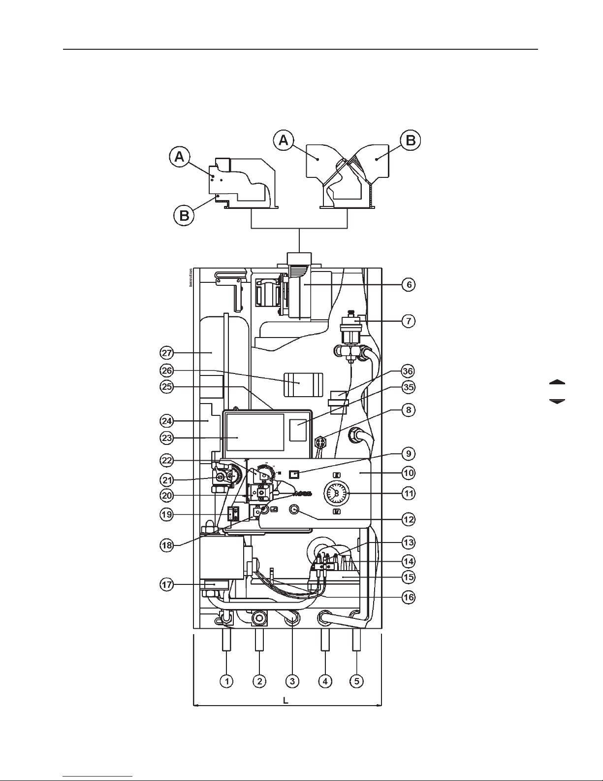
Figure 1 - BMS Front view
Coaxial discharge
Split discharge
A = Flue discharge
B = Air intake
8
GENERAL LA YOUT of the main components of model BMS
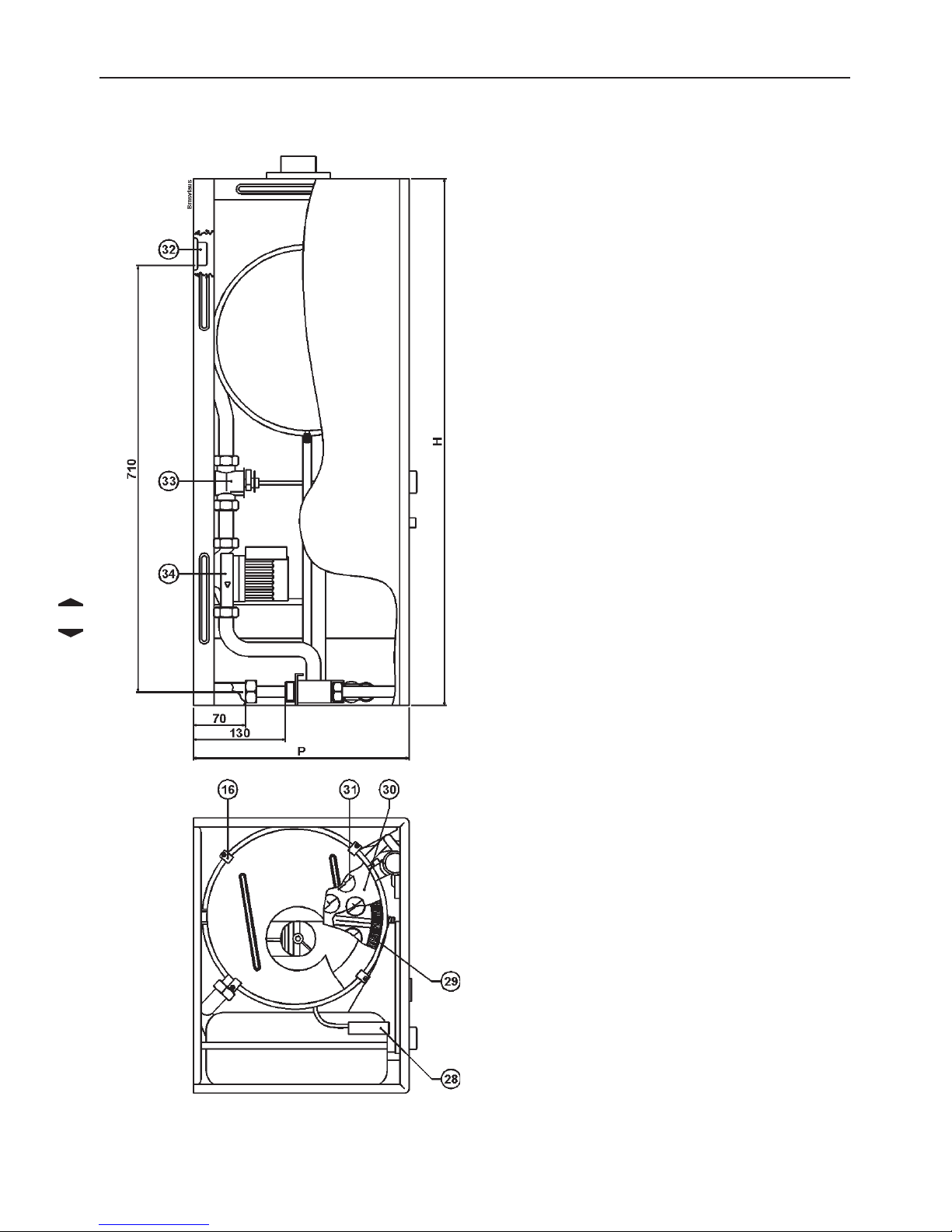
Figure 2 - BMS Side and top views
1 Central heating supply
2 Central heating return
3 Gas inlet
4 Domestic hot water outlet
5 Cold water inlet
6 Flue gas discharge fan
7 Automatic air vent
8 Thermostat bulb pocket
9 Gas valve service switch
10 Instrument panel
11 Temperature-pressure gauge
12 Failure lamp indicator
13 Ignition and detection electrodes
14 Burner
15 Gas manifold
16 Exchanger shell clamps
17 Gas valve
18 High limit thermostat
19 Power and circulator pump switches
20 Domestic hot water priority
thermostat
21 Central heating regulation knob
22 Heater temperature control
23 Electrical control board
24 Ignition module
25 Electrical plastic cover
26 Electrical junction box
27 Expansion tank
28 Pressure switch
29 Domestic water heat exchanger
30 Heat exchanger
31 Turbulator
32 Support bracket
33 Central heating regulation valve
34 Circulator pump
35 Transformer
36 Low water cut-off
9
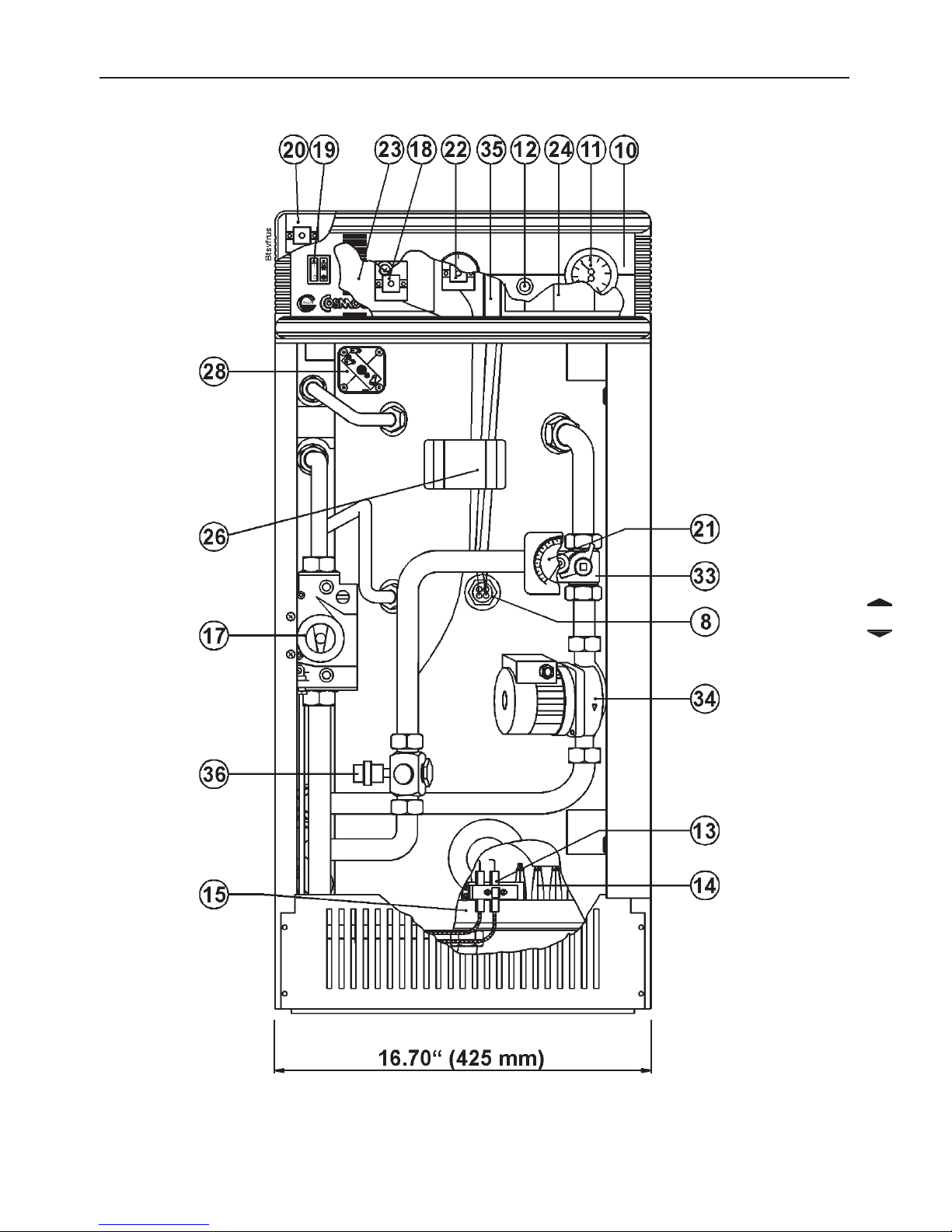
GENERAL LA YOUT of the main components of model BTS
Figure 3 - BTS Front view

10
GENERAL LA YOUT of the main components of model BTS
1 Central heating supply
2 Central heating return
3 Gas inlet
4 Domestic hot water outlet
5 Cold water inlet
6 Flue gas discharge fan
7 Automatic air vent
8 Thermostat bulb pocket
9- 10 Instrument panel
11 Temperature-pressure gauge
12 Failure lamp indicator
13 Ignition and detection electrodes
14 Burner
15 Gas manifold
16 - 17 Gas valve
18 High limit thermostat
19 Power and circulator pump switches
20 Domestic hot water priority
thermostat
21 Central heating regulation knob
22 Heater temperature control
23 Electrical control board
24 Ignition module
25 - 26 Electrical junction box
27 Expansion tank
28 Pressure switch
29 - 30 - 31 - 32 - 33 Central heating regulation valve
34 Circulator pump
35 Transformer
36 Low water cut-off
A Flue discharge
B Air intake
Figure 4 - BTS side view
11
A INSTALLATION INSTRUCTIONS
1 Operating and adjusting the
output to the radiation system
The COSMOGAS heater can be installed in
any domestic or light commercial building
where the maximum BTU/H required is not
greater than 88,800 BTU/H.
The unit has a internal mixing valve (heating
side only) that can be adjusted to regulate
the supply water temperature delivered to
the heating system.
The heating system will not receive any water
unless the water temperature inside of the
heater is at a minimum of 140°F. The heater
built-in domestic hot water priority thermostat
will cease the power to the circulator until
the temperature is greater than 140°F.
2 Location
This space/water heater unit is not intended for
outdoor installation. Choose a location centralized
to the piping system along with consideration to
the vent pipe length. Additionally, you will need to
place the space/water heater so that the controls,
drain, inlet/outlet, and gas valve are easily
accessed. Also, care must be exercised when
choosing the location of this appliance, where
leakage from the safety relief valves, leakage from
related piping, or connections, will not result in
damage to the surrounding areas, or to the lower
floor of the building.
No valve is to be placed between the safety relief
valves and the heater. The discharge from the
temperature and pressure relief valve must be
conducted to a suitable place for disposal. No
reducing coupling or other restriction shall be
installed in the discharge line. The discharge line
should allow complete drainage of both valve and
line.
3 Installation
The installation must conform to local codes and
ordinances or, in the absence of local codes, the
National Fuel Gas Code ANSI Z 223.1/NFPA 54
- 1984. When installed the appliance must be
electrically grounded in accordance with the
National Electrical Code, ANSI/NFPA No.70 -
1987.
For Canada, the installation should conform to
CGA B149.1 INST ALLA TION CODES and/or local
installation codes.
The gas supply piping system should be tested
before the heater is connected.
The heater, (complete with all its parts: external
jacket, intake and discharge flue pipes, etc.), must
be installed leaving a distance of at least 10 cm,
(4”), from sidewalls and ceiling.
Installation of the BTS combi directly on combustible
flooring such as carpeting shall be installed on a
metal or wood panel extending behind the full width
and depth of the appliance by at least 3”, (76.2
mm), in any direction or, if the appliance is installed
in an alcove or closet, the entire floor shall be
covered by the panel.
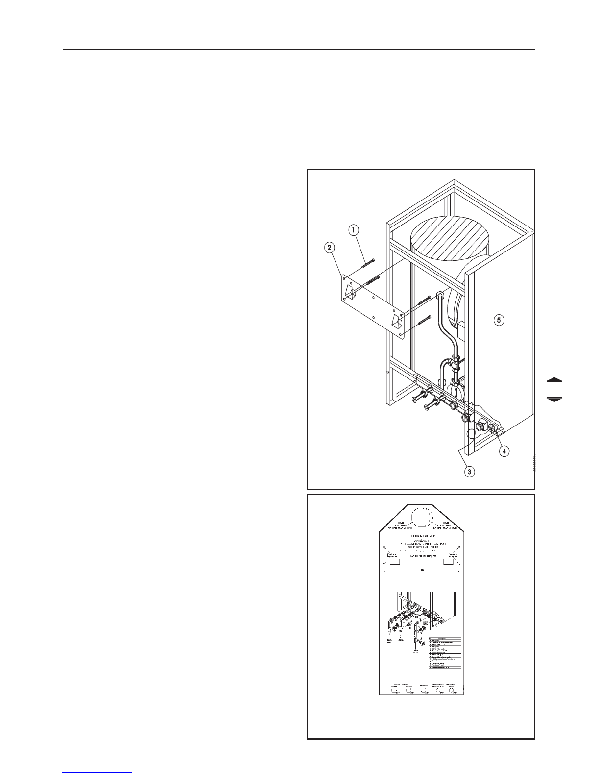
Figure 5 - Installation template, Only
for model BMS
Figure 4A

12
3.1 Installation
template
ONL Y model BMS is provided
with an installation template
to facilitate proper installation
alignments (See figure 5
below).
3.1.1 Clearances for
installation
The figures 5A and 5B show the
proper distances to keep from
any obstacle pertaining to the
support bracket (2) or to the wall.
The procedure for installing the
BMS is as follow:
1) - Take the support bracket (2)
and choose a position with proper
clearances, as per Figures 5A &
5B. A minimum clearance of 40”
(1000mm) is required from the
front of the heater.
WARNING: Please take caution
when choosing a mounting
surface for the heater. The
weight of the heater with water
is approximately 165 lbs. Make
certain that the wall can support
such weight.
2) Screw the bracket to the wall.
The screws MUST screwed in
correspondence of the 16"
vertical studs (see figures 4A and
5A)
3) Place the template onto the
support bracket and make all
rough-in holes for the piping to
the heater. The hole for the
coaxial flue vent kit discharge may
also be cut at this time.
4) Install the heater on the support
bracket and secure all of the
connections.
Figure 5A - Clearances for model BMS
Figure 5B - Clearances for model BTS
A INST ALLA TION INSTRUCTIONS

13
A INSTALLATION INSTRUCTIONS
3.2 Safety Relief Valve
An ASME approved safety relief valve, (set at
30 psi), must be installed in a vertical
position on the outlet side of the central
heating system, and as close as possible
to the heater. There must be no valves
between the safety relief valve and the heater.
Manually operate the safety relief valve at
least once a year to ensure proper operation.
Precaution must be taken prior to operating
the safety relief valve, to avoid contact with
hot water coming out of the safety relief valve
and to prevent water damege.
If the safety relief valve discharges
periodically, this may be due to thermal
expansion in a closed water supply system.
Contact the water supplier or local plumbing
inspector on how to correct this situation.
Do not plug the safety relief valve.
3.3 Heating supply and Return
The central heating supply and return pipes
are marked with different colored caps,
(supply red and return blue).
If there are any heating elements above
heater level, it is advisable to install a check
valve on the supply pipe to prevent “natural
circulation” phenomena from occurring.
If the heater is to be connected to an existing
system it is advisable to wash out and
remove any deposits from inside the existing
pipes, and install a filter at the lowest point
to trap any additional impurities when it is
running.
This equipment is designed for use in a
closed loop system.
Installation schematics are found in figures
23 to 28.
WARNING !!! All the schematics in figures
23 to 28 are only samplesl. Safety apparatus,
pipe diameters, and auxiliary accessories,
must be verified by a qualified personnel only
and in accordance with the national and/or
local codes.
3.3.1 Installation of two heaters
Iinstalling two heaters in parallel. Follow the
schema in the figure 23
3.3.2 Installation of three or more
heaters
Installing three or more heaters in parallel.
Follow the schema in the figure 24
3.3.3 Radiant heating installation
When the heater is used in conjuction with
radiant heating, it is imperative that the tubing
contains an oxygen diffusion barrier. If you
are unsure whether or not the tubing has a
barrier, a heat exchanger must be used to
protect the heater from oxygen corrosion
(See figure 25). This situation will also occur
if the heater is used on an open-loop system
where new, cold-fill water is introduced into
the system. The oxygen will remove itself
from solution and react chemically with the
ferrous components (i.e. steel), causing
them to rust and corrode. THIS TYPE OF
FAILURE IS NOT COVERED BY THE
WARRANTY!
3.3.4 Used of glycol
If glycol is used with the heater, the glycol
must be recognized as safe or approved by
the United States Food and Drug
Administration for food contact as listed in
Code of Federal Regulations, title 21, part
182 of the Food Additive Regulations. Any
additives introduced into the heating system
must be recognized as safe by the United
States Food and Drug Administration. If a
non-approved additive is used, it can cause
serious health problems or possibly
death.The pressure of the heating system
side of the heater must be fitted with devices
(automatic water feed/pressure reducing
valve not to exceed 30 psi) arranged to
function automatically in order to maintain
the pressure of the heating side at a level
below that of the potable water leaving the
heat exchanger.

14
3.4 Domestic Hot and Cold water
The domestic hot water flow restrictor must be
installed on the cold water inlet, (Refer to figure
25, 26, 27 and 28).
For servicing purposes, install a shut-off
valve upstream from the cold water inlet.
The heater’s thermostat can be regulated to
provide domestic hot water between 100°F
and 180°F. Water temperature over 125°F
can cause severe burns instantly. Since it is
required that the heater water temperature
reach above 140°F in order for the heating
system side of the unit to operate, it is
imperative that a mixing valve be installed
external of the heater to further regulate
the temperature of the domestic hot water
(See figures 23, 25, 26, 27 and 28). Failure
to install a domestic side mixing valve will
result in severe burns!
Piping and components connected to the
water heater for space heating shall be
suitable for use with potable water, and shall
not be connected to any heating system or
components previously used with a nonpotable water heating appliance.
The domestic hot water circuit needs an
ASME approved pressure relief valve, set at
150 psi, installed as close as possible to
the heater. There must be no valves
between the relief valve and the heater . The
relief valve discharge pipe must not be
restricted or plugged.
3.5 Water Hardness
In hard water areas (above 150 p.p.m), it is
recommended that a suitable water
treatment device (softener with filters) be
installed. Excessive buildup of minerals in
the heat exchanger can cause a nonwarranty failure. Water hardness can be
determined by using the standard test or by
checking with your local water authority.
Toxic chemicals, such as used for heater
treatment, should not be introduced into the
potable water used for space heating.
3.6 Gas Supply
Before making any gas connections, verify
that the heater is being supplied with same
gas type as indicated on the rating plate.
The rating plate is located on the front of the
BMS, and is located on the front door of the
BTS. This heater has orifices which will
operate at an altitude of up to 2,000 feet.
For installations in higher elevations, downrate the heater by 10%.
Install a manual gas cock outside of the
heater. Refer to Figures 1 and 3, item 3, for
the gas inlet location of the heater.
Gas piping to the heater must be sufficient
to guarantee a supply of gas to meet
maximum requirements. See Table 1 for
max. and min. values of gas pressure (Back
of manual).
All piping must comply with local codes
and ordinances or with the National Fuel
Gas Code, (ANSI Z223.1 NFPA No. 54),
whichever applies.
The appliance and its individual shutoff
valve must be disconnected from the gas
supply piping system during any pressure
testing of that system at test pressures in
excess of ½ psig, (3.5 kPa).
The appliance must be isolated from the
gas supply piping system by closing its
individual manual shutoff valve during any
pressure testing of the gas supply piping
system at test pressures equal to or less
than ½ psig, (3.5 kPa).
A INST ALLA TION INSTRUCTIONS
15
A INSTALLATION INSTRUCTIONS
Length of Gas Pipe Capacity of Gas Pipe Size in MBTUH
1/2" 3/4" 1" 1 1/4"
10'
132 278 520 1050
20'
92 190 350 730
30'
73 152 285 590
40'
63 130 245 500
50'
115 215 440
75'
93 175 360
100'
79 150 305
150'
64 120 250
Additional length
to be added for
1.3' 1.7' 2.2' 2.7'
each bend or tee
3.6 Gas Supply (cont.)
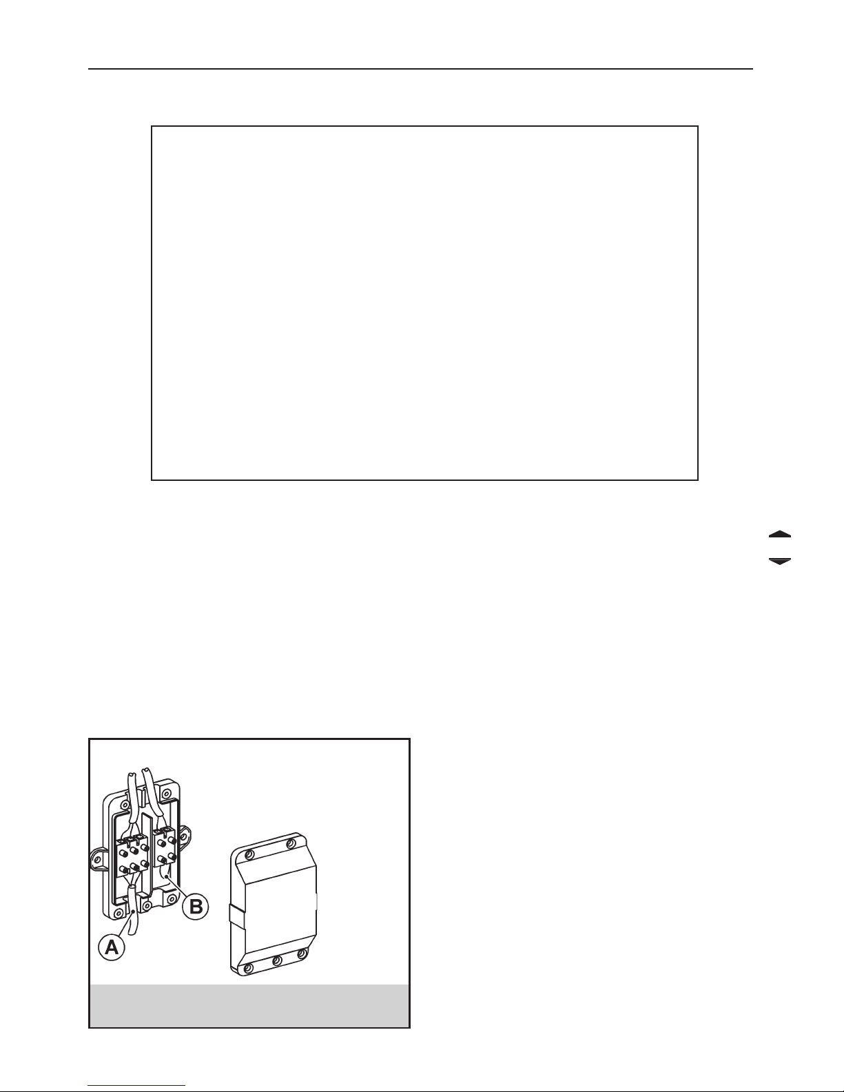
A Electrical supply
connection
B Room thermostat
connection
Figure 6 - Connecting the room
thermostat and electrical supply
3.7 Room Thermostat Connection
This is installed by removing the electrical junction
box cover indicated in fig.6, (see fig.1 and 3, item
26), and connecting the two wires of the room
thermostat, or zone valve control thermostat, to
the low voltage terminals, (figure 6, item B). NOTE:
first remove factory installed jumper from
terminals. The room thermostat must always
be located in a point of the house where the
temperature is not subject to sudden changes.
3.8 Electrical Supply Connection
The heater must be connected to a 115V
60Hz, single phase electrical supply fused
to 15 amps,
Grounding is required as well as the
installation of a main emergency switch
immediately upstream from the heater.
An electrical junction box (see figures 1
and 3, item 26) is provided for connections
for both the line voltage of 1 15V 60 Hz (See
figure 6 item A) , and the room thermostat
at low voltage of 24Vac (See figure 6 item
B).
The cable wire of the line voltage must be
insered into the heater, through the p asscable positioned in the side of the idraulic
connections (see figure 6A and 6B).
16
A INST ALLA TION INSTRUCTIONS
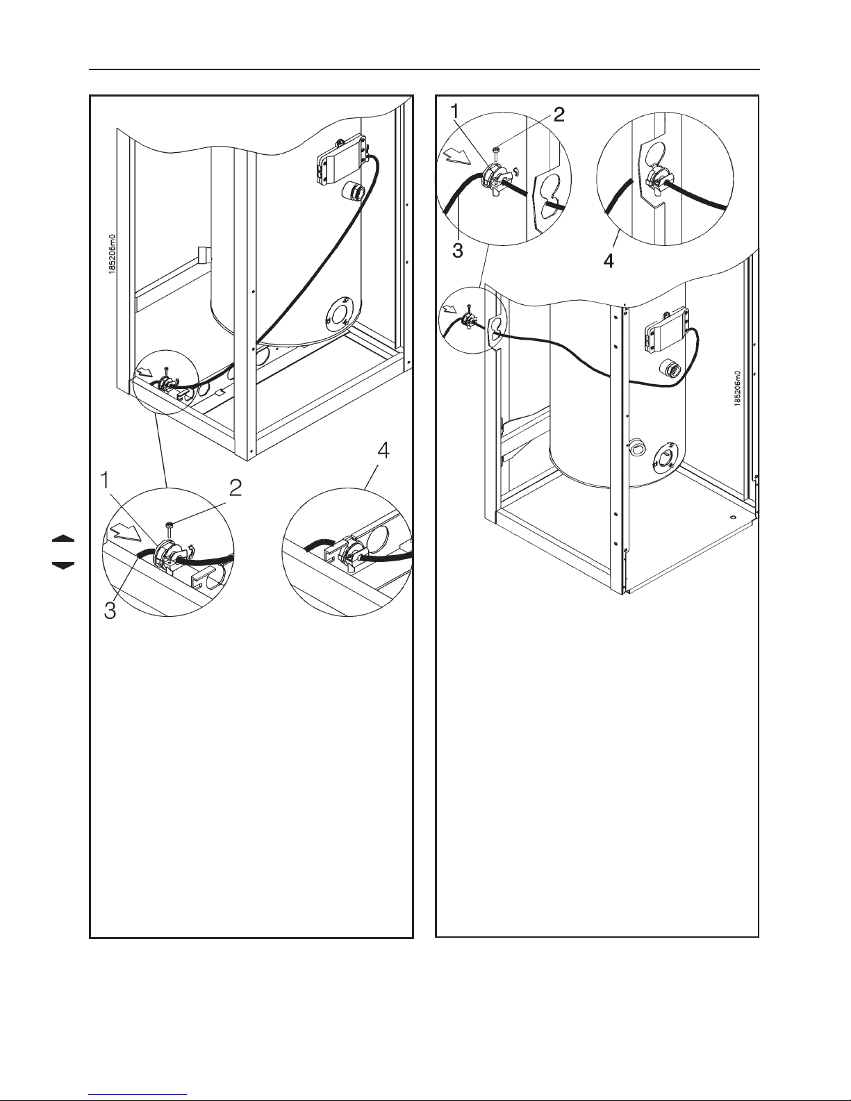
Figure 6A - Installation of the electrical
supply cable on the model BMS
a) Remove or loosen screw (2)
b) Pop- out the passage tunnel for the
supply cable. Pass the supply cable
through the passage (1)
c) Connect the supply cable to the
junction box
d) Tighten screw (2);
e) Re-insert the passage tunnel into its
position (4).
f) Feed wire to junction box and connect
as shown in Figure 6.
Figure 6B - Installation of the electrical
supply cable on the model BTS
a) Remove or loosen screw (2)
b) Pop- out the passage tunnel for the
supply cable. Pass the supply cable
through the passage (1)
c) Connect the supply cable to the
junction box
d) Tighten screw (2);
e) Re-insert the passage tunnel into its
position (4).
f) Feed wire to junction box and connect
as shown in Figure 6.

17
A INSTALLATION INSTRUCTIONS
4 VENTING SYSTEMS
This heater can be fitted with either a
concentric or split type venting system.
Particular attention must be taken when
installing the vent pipes that go through the
wall to the outside. It must always be
possible to carry out routine maintenance
operations of the flue. The vent pipe must
be installed in such a way that it can be
removed, if needed, in the future. Hence, a
suitable sheath should be prepared in which
to insert the vent pipe. Both venting systems
are suitable for venting through a wall 1” to
24” thick.
The connection of the vent air intake system
to the heater can turn 360°, which means in
all directions, making installation extremely
easy.
To turn it just loosen the securing screws on
the base of the vent elbow where it attaches
to the heater, turn to desired position, then
tighten the screws without forcing them.
You must place the terminal in an open area,
and follow the following guidelines:
• Make certain that exhaust gas does not
re-circulate back into the intake pipe.
• Never vent into a walkway or patio area,
or an alley , or otherwise public area less than
7ft from the ground level. This is to prevent
anyone from walking into the vent;
• Never vent over or under a window or over
a doorway;
• Never install a heat saver or similar
product to capture waste heat from exhaust;
• Always have vent 1ft above ground level,
away from shrubs and bushes.
• Follow local gas codes in your region or
refer to National Fuel Gas Code, or Can
B149.1 INST ALLATION CODES.
• Always have vent at least 3ft from an
inside corner of outside walls.
• Maintain at least 4ft clearance to electric,
gas meters and exhaust fans.
• Always place screens in all openings in
intake and exhaust to prevent foreign matter
from entering the heater.
• The vent terminals, (concentric, split type
exhaust), must be a minimum of 1ft above
the ground level.
• If split type vent will be venting into a
chimney, make certain that no other
appliances are vented into it. This powervented heater must not share a chimney . Vent
exhaust terminal should be inserted into, but
not beyond, inner wall of chimney.
Do not vent into transient pipe. Warranty will
be void.
CAUTION! - Take all precautionary measures
to allow the angle of the flue to run down slightly
to the outside, NEVER rising. Anticipate for
all horizontal pipes, an inclination of 1/4” per
foot toward the discharge. If a vertical pipe
follows a horizontal one, place a condensation
discharge fitting in the lowest part of the vertical
pipe. A condensation discharge pipefitting
must also be used for vertical discharge pipe
installations directly from the heater with a pipe
whose length is more than 10”.
During normal operating conditions, the
heater will have exhaust gases exiting
from the flue pipe. The smoke will be
heavier on some days than on others. This
is due to the outdoor weather conditions
(the temperature, humidity, etc.), and is
extremely common.
4.1 Concentric Flue (Coaxial)
The (Coaxial) concentric vent, (air inlet and
flue outlet), system consists of 2 pipes: the
outer one for fresh air intake, the inner pipe
for flue exhaust discharge.
With optional pipe, it is possible to increase
the overall length up to 15ft (4.5 m).
There are also 90° concentric elbows
available, if they are installed, there will be a
loss of draught equal to that caused by 3ft,
(1 m), of straight pipe.
Connections between the various parts must
be secured by using self-tapping screws,
(see fig.9). The vents stainless steel end
terminal must always come completely out
of the outer pipe. If for any reason the intake
grid is blocked, the heater will not receive
enough air for combustion and the burner
would fail to ignite.
 Loading...