

Page 1
62403690 - R00 03-10-2016_HU
INSTALLATION,
OPERATING AND
MAINTENANCE MANUAL
AGUADENS
WALL-MOUNTED GAS
CONDENSING WATER
HEATERS
Page 2

2
AGUADENS
COSMOGAS
INDEX
1 - GENERAL SAFETY RECOMMENDATIONS ..................................................................................................4
1.1 - National laws and regulations .................................................................................................................................. 5
2 - GENERAL INFORMATION .............................................................................................................................6
2.1 - Presentation ............................................................................................................................................................. 6
2.2 - Model overview ........................................................................................................................................................ 6
2.3 - Manufacturer ............................................................................................................................................................ 7
2.4 - Symbols key ............................................................................................................................................................. 7
2.5 - Maintenance ............................................................................................................................................................. 7
3 - MAIN COMPONENTS .....................................................................................................................................8
4 - OPERATION .................................................................................................................................................12
4.1 - Operation and intended use of the appliance ........................................................................................................ 13
4.2 - Examples of installation ......................................................................................................................................... 14
5 - INSTALLATION .............................................................................................................................................16
5.1 - Opening the packaging .......................................................................................................................................... 16
5.2 - Dimensions and minimum safety clearances ......................................................................................................... 16
5.3 - Choosing suitable installation location ................................................................................................................... 16
5.4 - Mounting the appliance .......................................................................................................................................... 16
5.5 - Domestic hot and cold water .................................................................................................................................. 16
5.6 - Gas ......................................................................................................................................................................... 17
5.7 - Condensate drain ................................................................................................................................................... 18
5.8 - Safety valve ............................................................................................................................................................ 18
5.9 - Hydraulic and gas connections .............................................................................................................................. 19
5.10 - Water softener (on request) ................................................................................................................................. 19
5.11 - Electrical connections ........................................................................................................................................... 20
5.11.1 - Power supply cable connection ............................................................................................................... 21
5.11.2 - CR04 remote Time control (on request) .................................................................................................. 21
5.12 - External secondary return conguration ......................................................................22
5.13 - Connection water heater to Storage tank ............................................................................................................. 23
5.13.1 - Anti- legionella precaution ....................................................................................................................... 23
5.14 - Flue systems ........................................................................................................................................................ 25
5.14.1 - Exhaust ue with indipendent combustion air grille type B23 ................................................................. 26
5.14.2 - “Split 80/80PP” System (polypropylene) (Type C43; C53; C83) AGUADENS 16 and 22 ....................... 27
5.14.3 - “Split 80/80PP” System (polypropylene) (Type C43; C53; C83) AGUADENS 37 ................................... 28
5.14.4 - “Split 80/80PP” System (Type C43; C53; C83): accessories available ................................................... 29
5.14.5 - “Split 80/80PP” System (Type C43; C53; C83): installation examples ................................................... 30
5.14.6 - “60/100PP vertical coaxial” System (polypropylene) (C13; C33 Type) ................................................... 31
5.14.7 - “60/100PP horizontal coaxial” System (polypropylene) (C13; C33 Type) ............................................... 32
5.14.8 - “60/100PP Coaxial” System: accessories available ................................................................................ 33
5.14.9 - “60/100PP Coaxial” System: installation examples ................................................................................ 34
5.14.10 - “80/125PP vertical coaxial” System (polypropylene) (C13; C33) .......................................................... 35
5.14.11 - “80/125PP Coaxial” System: accessories available .............................................................................. 36
5.14.12 - “80/125PP Coaxial” System: installation examples .............................................................................. 37
6 - OPERATING .................................................................................................................................................38
6.1 - Operating ............................................................................................................................................................... 38
6.1.1 - User instructions ....................................................................................................................................... 38
6.1.2 - Filling the condensate drain siphon .......................................................................................................... 38
6.2 - General recommendations regarding the supply of gas ........................................................................................ 38
6.3 - Type of gas for which the appliance is regulated. .................................................................................................. 39
6.4 - Conversion of the appliance from one type of gas to another ................................................................................ 39
6.5 - Ignition .................................................................................................................................................................... 41
6.6 - Check the gas supply pressure .............................................................................................................................. 41
6.7 - Measurement and adjustment of CO2 levels ......................................................................................................... 42
6.8 - Self-learning and calibration of the minimum and maximum capacity output ........................................................ 43
6.9 - Adjust the domestic hot water ow rate .................................................................................................................. 43
6.10 - Check the capacity input ...................................................................................................................................... 43
7 - USE ...............................................................................................................................................................44
7.1 - Display ................................................................................................................................................................... 44
7.2 - Ignition procedure .................................................................................................................................................. 44
7.3 - “User menu” ........................................................................................................................................................... 45
7.4 - Adjustment of the domestic hot water temperature ................................................................................................ 45
7.5 - Timings of the various functions ............................................................................................................................. 45
7.6 - Display Energy Saving mode ................................................................................................................................. 45
Page 3

3
AGUADENS
COSMOGAS
INDEX
7.7 - “User menu” Parameters ........................................................................................................................................ 46
7.8 - “Installer menu” & parameters ................................................................................................................................ 47
7.9 - Diagnostics ............................................................................................................................................................. 48
7.9.1 - Diagnostics “Loc” block fault codes and potential solution ....................................................................... 49
7.9.2 - Diagnostics “E” error fault codes and potential solutions .......................................................................... 51
7.10 - Switch ON and OFF the appliance ....................................................................................................................... 52
8 - MAINTENANCE ............................................................................................................................................53
8.1 - Care and maintenance ........................................................................................................................................... 53
8.1.1 - Service recall ............................................................................................................................................ 53
8.1.2 - Address reported problems ....................................................................................................................... 53
8.1.3 - Check all piping for gas leaks ................................................................................................................... 53
8.1.4 - Verify ue and air lines in good condition and sealed tight; ...................................................................... 53
8.1.5 - Check system water pressure/system piping/expansion tank; ................................................................. 53
8.1.6 - Check control settings ............................................................................................................................... 53
8.1.7 - Check wiring and connections .................................................................................................................. 54
8.2 - Casing removal ...................................................................................................................................................... 54
8.3 - Burner and fan removal .......................................................................................................................................... 55
8.3.1 - Thermal insulations ................................................................................................................................... 55
8.4 - Gas burner and heat exchanger outer surface cleaning procedure ....................................................................... 55
8.5 - Condensate siphon cleaning procedure ................................................................................................................. 57
8.6 - Ignition and ame isonising electrode position ....................................................................................................... 58
8.7 - Circulation pump replacement procedure .............................................................................................................. 58
8.8 - Domestic water ow meter replacement procedure ............................................................................................... 59
8.9 - Safety valve replacement procedure ...................................................................................................................... 59
8.10 - Procedure for draining the water heater ............................................................................................................... 60
8.11 - Fan test mode procedure ..................................................................................................................................... 60
8.12 - Gas burner minimum and maximum performance test mode procedure ............................................................. 60
8.13 - Checking the ionisation current ............................................................................................................................ 61
8.14 - Water temperature measurement sensor testing procedures .............................................................................. 61
8.15 - Operational wiring diagram .................................................................................................................................. 62
8.16 - Multi-wire wiring diagram ..................................................................................................................................... 64
9 - TECHNICAL DATA ........................................................................................................................................66
10 - COMMAND MENU DIAGRAM ....................................................................................................................67
11 - ENGINEERS TEST MODE..........................................................................................................................68
12 - CE DECLARATION OF CONFORMITY ......................................................................................................69
Page 4

4
AGUADENS
COSMOGAS
If you smell gas
1. - Close the gas cock.
2. - Ventilate the room.
3. - Do not switch on any electric device, telephone included.
4. - From another room, call a professionally qualified
technician immediately or the gas supply company. Call
the Fire Service if the former are not available.
If you can smell combustion products
1. - Switch the appliance off.
2. - Ventilate the room.
3. - Call a professionally qualied technician.
Explosive or highly ammable products
Do not store or use explosive or highly ammable materials
such as paper, solvents, paints, etc...in the same room where
the appliance is installed.
Installation, modications
The gas appliance must be installed, calibrated or modied
by professionally qualied staff, in compliance with National
and local Standards, as wells as the instructions in this
manual.
Incorrect installation or poor maintenance can cause
injury/damage to persons, animals or objects, for which
the manufacturer cannot be deemed liable.
The appliance must be connected to an approved ue
system. Failure to comply with this regulation can lead to
serious risks for people and animals
A domestic hot water temperature level exceeding 51°C
can cause permanent injury/damage to people, animals and
objects. Special care should be taken to protect children, the
elderly and those with special needs using non-accessible
blending valves to limit the ow hot water temperature at
outlets.
The water heater ue system must not be modied by
unqualied person.
The ue system terminals should not be obstructed in any
way.
Do not leave parts of the packaging and any replaced parts
within the reach of children.
Seal the adjustment devices after every calibration.
In agreement with the provisions for use, the user must
keep the installation in good working order and guarantee
reliable and safe operation of the appliance.
We also highlight the importance of an annual scheduled
maintenance contract with a professionally qualified
technician.
The end user must have maintenance performed on the
appliance only by professionally qualied technicians in
accordance with this manual and in full compliance with
both local and national standards.
Before performing any cleaning or maintenance, disconnect
the appliance from the mains power supply.
After having performed any cleaning or maintenance works,
make sure that all internal etc.
This appliance is not intended for use by persons (including
children) with reduced physical and sensory conditions or
lack of experience and knowledge, unless they have been
given supervision or instruction concerning use of the
appliance by a person responsible for their safety.
This manual is an integral and essential part of the product
and must be kept carefully by the user, for possible future
consultation. If the appliance must be transferred or if you
should move and leave the unit to another user, always
ensure that this manual remains with the new user and/
or installer.
Any accessories or kits which might be added must be
original Cosmogas products.
This appliance must be intended only for the use for which
it has been expressly declared: production of domestic hot
water for civilian use.
Any contractual and extra contractual liability of the
manufacturer is excluded for damage caused by installation
errors or errors in use and however due to failure to comply
with the instructions given by the manufacturer or by failure
to comply with applicable national and/or local laws.
For safety reasons and respect for the environment, the
packaging elements must be disposed of in the relevant
separate waste collection centres.
In case of breakdown
In the case of appliance breakdown and/or malfunctioning,
deactivate it and do not attempt any repairs. Contact a
professionally qualied technician only. If components must
be replaced for repair to be successful, only use original spare
parts. Failure to comply with the above can jeopardise the
safety of the appliance.
Professionally qualied technician.
Professionally qualied technicians with certied training
covering gas boilers and/or gas water heaters as envisioned
by the law.
Technical drawings
All drawings in this manual relating to electrical wiring,
hydraulic and gas layouts are purely indicative. The external
services such as electrical cable types and sizes, water
services pipes and gas services must always be checked
by a professionally qualied technician or engineer to verify
compliance with all relevant standards, Laws and codes of
good practice.
Carbon Monoxide.
Every year deaths and serious injuries occur due to carbon
monoxide poisoning. This tragedies are avoidable if certain
preventative measures such as the following are undertaken:
Ensure that all boilers, water heaters, room heaters, stoves
and hobs which burn oil, natural gas, LP gas, coal, peat,
wood and wood pallets are serviced regularly. Servicing
is needed at least once per year to ensure safety. the
service person should be qualied and trained to service
the specic types of appliance
If an appliance is fitted in a dwelling, then a carbon
monoxide detector should always be tted. There are two
types avaiable: a simple detector works like a re alarm to
emit a loud noise and ashing light if carbon monoxide is
detected or a more sophisticated version which will also
switch off the appliance to provide more safety.
1 - GENERAL SAFETY RECOMMENDATIONS
Page 5

5
AGUADENS
COSMOGAS
1 - GENERAL SAFETY RECOMMENDATIONS
1.1 - National laws and regulations
- M.D. n°37 dated 22/01/2008 (former Law n°46 dated 05/03/90)
- Law n°10 dated 09/01/91
- Presidential Decree n°412 dated 26/08/93
- Presidential Decree n°551 dated 21/12/99
- Legislative Decree n° 192 dated 19/08/05
- Legislative Decree n° 311 dated 29.12.06
- UNI 7129 Standard
- UNI 7131 Standard
- UNI 11071 Standard
- IEC 64-8 Standard
All the gas appliances must be installed by a competent
and qualied person, in accordance with relevant clauses of
applicable standards and raccomandations. These include
but may not be limited to the following:
- I.S. 813 Domestic gas installations.
- I.S. 820 Non-Domestic gas installations.
- IEE Wiring Regulations.
- BS 5546:2010 - Specication for installation and maintenance
of gas-fired water-heating appliances of rated input not
exceeding 70 kW net.
- BS 5440-2:2009 - Flueing and ventilation for gas appliances
of rated input not exceeding 70 kW net (1st, 2nd and 3rd family
gases) specication for the installation and maintenance of
ventilation provision for gas appliances.
- BS 6644:2011 - Specification for the installation and
maintenance of gas-red hot water boilers of rated inputs
between 70 kW (net) and 1.8 MW (net) (2nd and 3rd family
gases).
- BS 6891:2005+A2:2008 - Installation of low pressure gas
pipework of up to 35 mm (R1 1/4) in domestic premises (2nd
family gas) specication.
- BS 5482-1:2005 - Code of practice for domestic butane and
propane gas burning installations. Installations at permanent
dwellings, residential park homes and commercial premises,
with installation pipework sizes not exceeding DN 25 for steel
and DN 28 for corrugate stianless steel or copper.
- BS 5482-2:AMD 12046: June 2001 - Domestic butane and
propane gas burning installations. Installations in caravans
and non-permanent dwellings.
- BS 5482-3:2005 - Domestic butane and propane gas burning
installations. Installations in boats yachts and other vessels.
- Building regulations issued by Department of the Environment
and Building Standards Regulations.
- Gas safety (Installation and Use) Regulations current issue.
- BS 6700 - Design, installation, testing and maintenance of
services supplying water for domestic use within buildings
and their cartilages - Specication.
- UK Health and safety at work Act.
- All relevant Building Regulations.
- Local Water Bye Laws.
- Water Regulations.
- Health & Safety legislation.
Failure to install this appliance correctly could lead to
prosecution. It is your own interest and that of safety to ensure
that the law is complied with. Manufacturer’s instructions must
not be interpreted as over-riding statutory obligations under
any circumstances.
Page 6

6
AGUADENS
COSMOGAS
2 - GENERAL INFORMATION
2.1 - Presentation
Congratulations! You have purchased one of the best
products on the market. Each individual part is proudly
designed, produced, tested and assembled within the
COSMOGAS establishment, thus guaranteeing the
best quality control.
AGUADENS XX
16 = Water heater with maximum heat input of 25,5 kW
22 = Water heater with maximum heat input of 32,0 kW
37 = Water heater with maximum heat input of 57,8 kW
Condensing, indoor, pre-mixed, ecological gas water heater.
2.2 - Model overview
Page 7
7
AGUADENS
COSMOGAS
2.3 - Manufacturer
COSMOGAS srl
Via L. da Vinci 16
47014 - Meldola (FC) Italia
Tel. 0543 498383
Fax. 0543 498393
www.cosmogas.com
[email protected]
2.4 - Symbols key
ATTENTION !!!
El ectric s hock haza rd. Failure to c omply wit h t hese
recommendations can jeopardise the good working order of
the appliance or cause serious damage to persons, animals
or objects.
ATTENTION !!!
General hazard. Failure to comply with these recommendations
can jeopardise the good working order of the appliance or
cause serious damage to persons, animals or objects.
Important indication symbol.
2.5 - Maintenance
It is recommended to perform regular yearly maintenance of
the appliance for the following reasons:
- to maintain a high yield and manage the domestic hot water
plant economically (with low fuel consumption);
- to achieve a high level of safety;
- to maintain the level of environmental compatibility of the
combustion high;
Offer your customer a scheduled maintenance contract.
2 - GENERAL INFORMATION
Page 8
8
AGUADENS
COSMOGAS
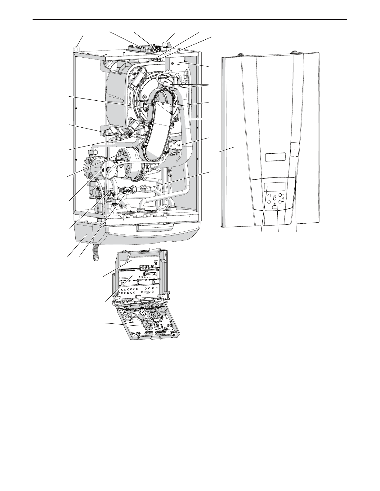
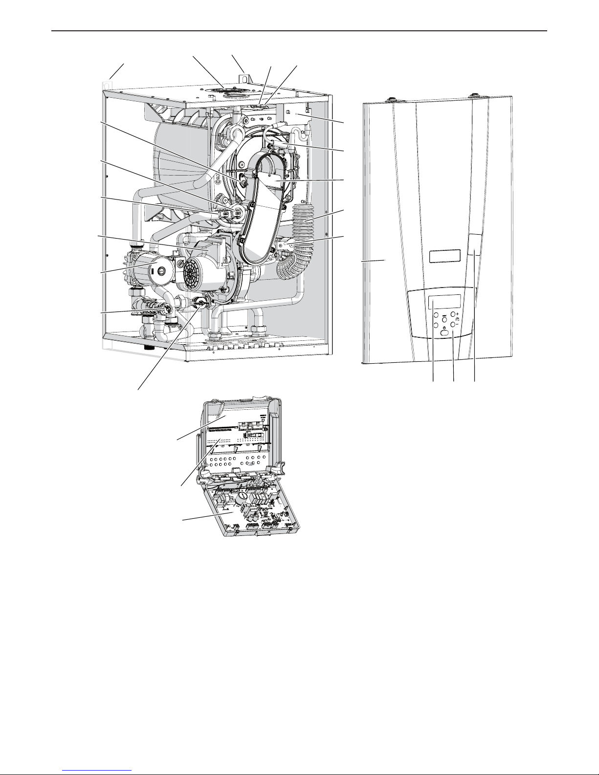
1 - Command and control board
2 - Electric connections board
3 - Electric control board box
4 - Lower cover
5 - ----------
6 - Water ow rate measuring device
7 - Cold water inlet temperature sensor (1007)
8 - Fan
9 - ---------10 - ----------
11 - Double D.H.W. output sensor (1001 and 1005)
12 - ---------13 - ---------14 - Pump
15 - Detection electrode
16 - Wall xing brackets
17 - ---------18 - ----------
19 - Combustion air and exhaust ue connection
20 - Combustion analysis points
21 - Exhaust ue temperature sensor (1006)
22 - Spark generator
23 - Ignition cables
24 - Combustion gases non-return valve.
25 - Air inlet manifold
26 - Gas valve
27 - Front casing
28 - Safety valve
29 - Display
30 - Control board
31 - Gas valve adjustment service access hatch
3 - MAIN COMPONENTS
Figure 3-1 - Water heater internal components
7
6
46
45
25
16
26
8
2
3
4
24
22
23
19
15
16
20
1
31
21
28
30
11
29
14
27
7
6
46
45
25
16
26
8
2
3
4
24
22
23
19
15
16
20
1
31
21
28
30
11
29
14
27
020003.01.057
Page 9
9
AGUADENS
COSMOGAS
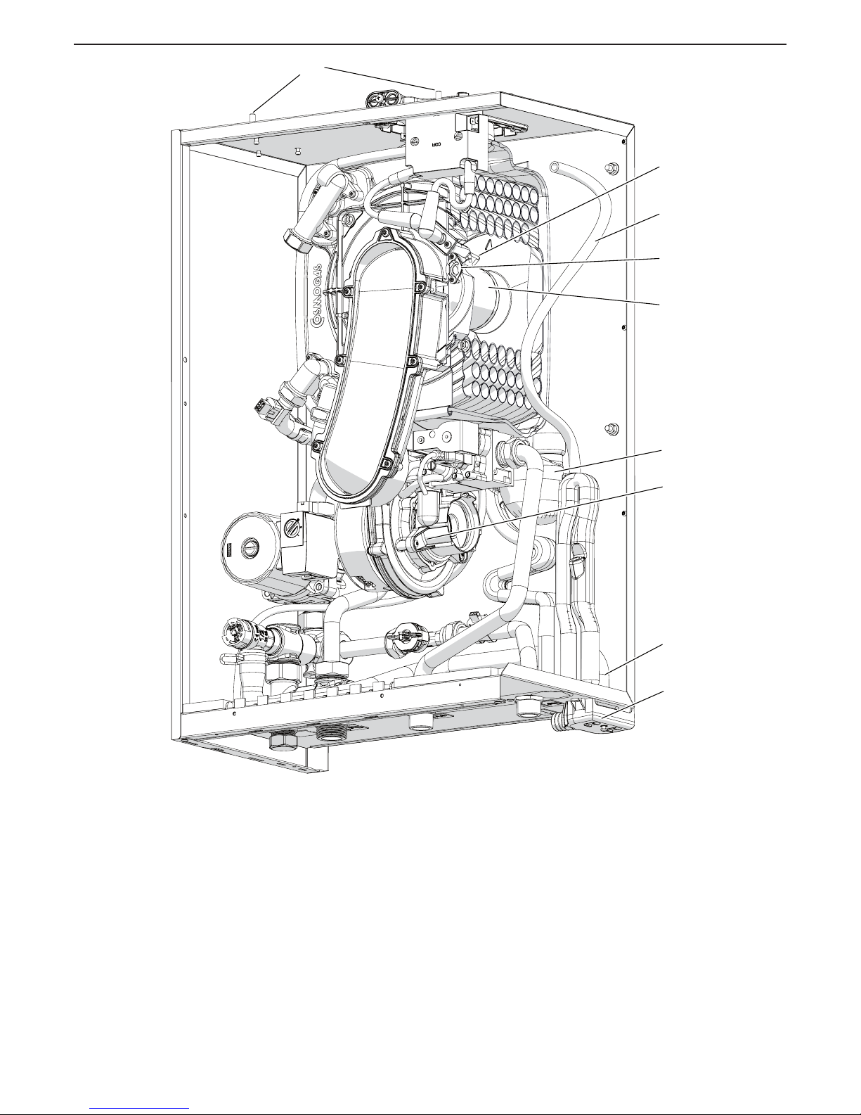
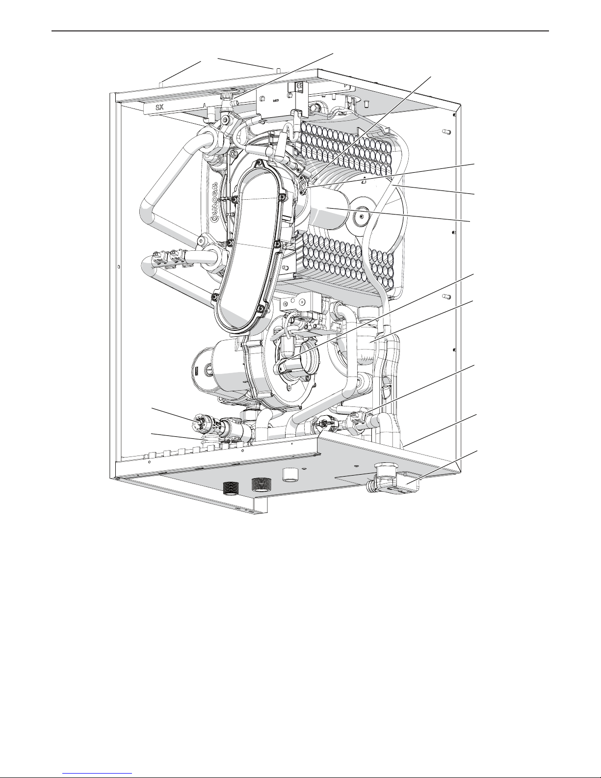
32 - ----------
33 - Front casing xing tabs
34 - ---------35 - Ignition electrodes
36 - Gas burner viewing port
37 - Flue condensate collection collar drain pipe (connected to siphon)
38 - Burner
39 - Air/gas mixing unit
40 - Condensate drain siphon
41 - Safety valve drain pipe
42 - ---------43 - Condensate collection tank
44 - ---------45 - Flue gas temperature protection fuse
46 - Temperature sensor D.H.W. (1002)
3 - MAIN COMPONENTS
Figure 3-2 - Water heater internal components
33
35
38
37
40
39
43
41
36
33
35
38
37
40
39
43
41
36
020003.01.058
Page 10
10
AGUADENS
COSMOGAS
1 - Command and control board
2 - Electric connections board
3 - Electric control board box
4 - ---------5 - ----------
6 - Water ow rate measuring device
7 - Cold water inlet temperature sensor (1007)
8 - Fan
9 - ---------10 - ----------
11 - Double D.H.W. output sensor (1001 and 1005)
12 - ---------13 - ---------14 - Pump
15 - Detection electrode
16 - Wall xing brackets
17 - ---------18 - ----------
19 - Combustion air and exhaust ue connection
20 - ---------21 - Exhaust ue temperature sensor (1006)
22 - Spark generator
23 - Ignition cables
24 - Combustion gases non-return valve.
25 - Air inlet manifold
26 - Gas valve
27 - Front casing
28 - Safety valve
29 - Display
30 - Control board
31 - Gas valve adjustment service access hatch
3 - MAIN COMPONENTS
Figure 3-3 - Water heater internal components
6
16
19
16
26
25
8
45
24
3
15
2
22
23
14
28
1
3130
21
11
46
29
27
6
16
19
16
26
25
8
45
24
3
15
2
22
23
14
28
1
3130
21
11
46
29
27
020008.01.019
Page 11
11
AGUADENS
COSMOGAS
32 - ----------
33 - Front casing xing tabs
34 - ---------35 - Ignition electrodes
36 - Gas burner viewing port
37 - Flue condensate collection collar drain pipe (connected to siphon)
38 - Burner
39 - Air/gas mixing unit
40 - Condensate drain siphon
41 - Safety valve drain pipe
42 - ---------43 - Condensate collection tank
44 - ----------
45 - High limit ue gas temperature fuse
46 - D.H.W. temperature sensor (1002)
47 - Air purge valve
3 - MAIN COMPONENTS
Figure 3-4 - Water heater internal components
41
28
33
40
41
37
43
7
38
47
35
39
36
41
28
33
40
41
37
43
7
38
47
35
39
36
020008.01.020
Page 12
12
AGUADENS
COSMOGAS
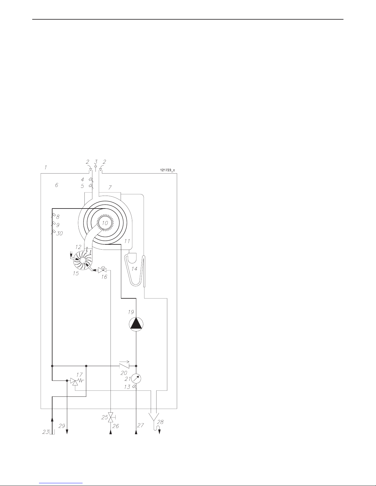
Key to gure 4-1:
1 = Water heater
2 = Combustion air intake
3 = Exhaust ue
4 = Exhaust ue temperature sensor (Par. 1006)
5 = High limit ue gas temperature fuse
6 = Sealed chamber
7 = Water collection tub
8 = Heat exchanger outlet temperature sensor 1 (Par. 1001)
9 = Heat exchanger outlet temperature sensor 2 (Par. 1005)
10 = Burner
11 = Heat exchanger
12 = Fan
13 = Cold water temperature sensor (Par. 1007)
14 = Condensate collection siphon
15 = Air/gas mixer
16 = Gas valve
17 = Safety valve
18 = ---------19 = Pump
20 = Non-return valve
21 = Water ow meter
22 = ---------23 = Cap
25 = Manual gas valve (optional)
26 = Gas inlet
27 = Cold water inlet
28 = Safety valve condensate drain funnel
29 = Hot water outlet
30 = Hot water sensor (Par. 1002)
4 - OPERATION
Figure 4-1 - Hydraulic layout
Page 13
13
AGUADENS
COSMOGAS
4 - OPERATION
4.1 - Operation and intended
use of the appliance
This product is a condensing gas appliance, intended for
the production of domestic hot water for use by people.
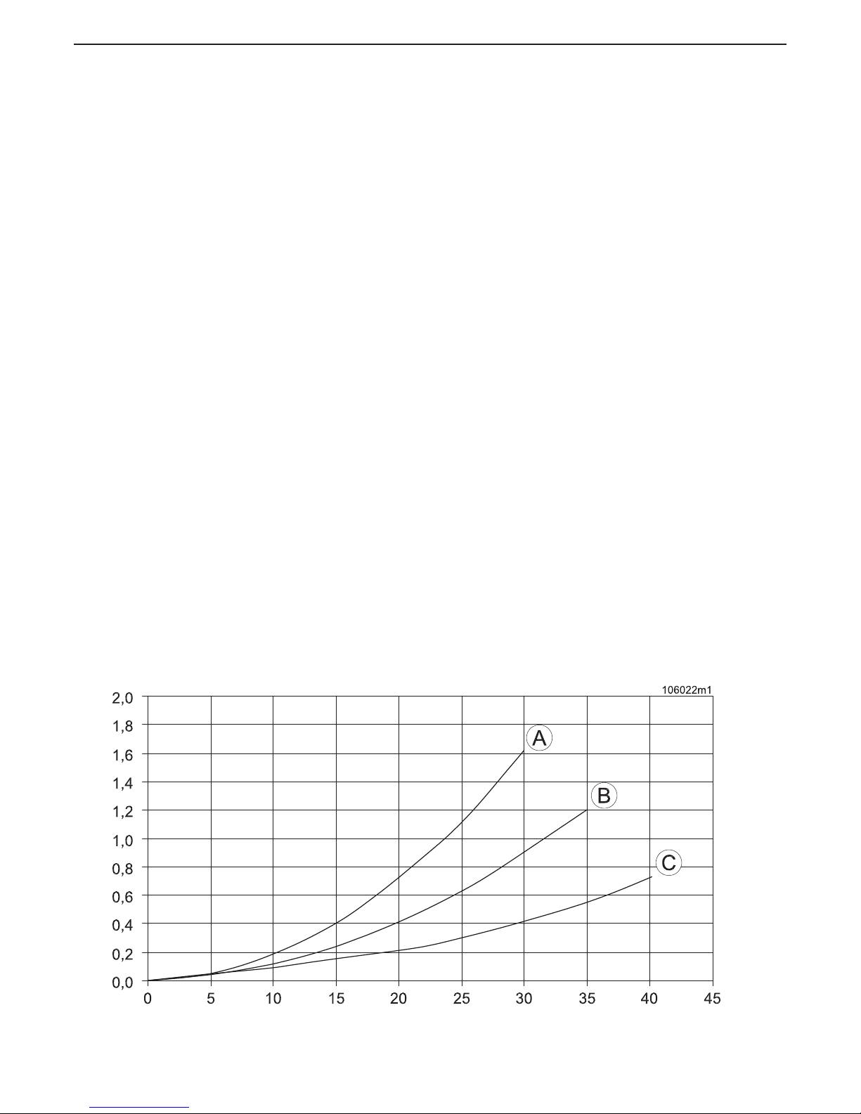
Consider the D.H.W. circulation pump performance curves
as illustrated in gure 4-2.
The temperature of the domestic hot water can be adjusted
by following the relevant procedure in section 7.4.
This appliance must be connected to a domestic hot
water distribution system which has adequately sized
pipes to convey the correct water volume and all pipes
should be tted with good quality insulation to optimise
the performance of the water heater.
Before installation of the domestic cold and hot water
services should be ushed thoroughly in order to remove
any residues or impurities which could compromise the
good working order of the appliance.
This appliance is not suitable for installation outdoors.
It must not be exposed to temperature below zero or
temperature above 50°C. Select a suitable sheltered
location for the appliance.
This appliance must be installed in a location which will
not cause damage to objects or property in the event of
water leaking from within the appliance or connections at
the appliance.
Check gure 5-1 concerning the minimum safety
distances for installation and future maintenance.
Figure 4-2 - Curve of the domestic water circuit losses
Head losses (bar)
Water ow rate (l/min)
Key to gure 4-2
A = Aguadens 16
B = Aguadens 22
C = Aguadens 37
Page 14
14
AGUADENS
COSMOGAS
4 - OPERATION
4.2 - Examples of installation
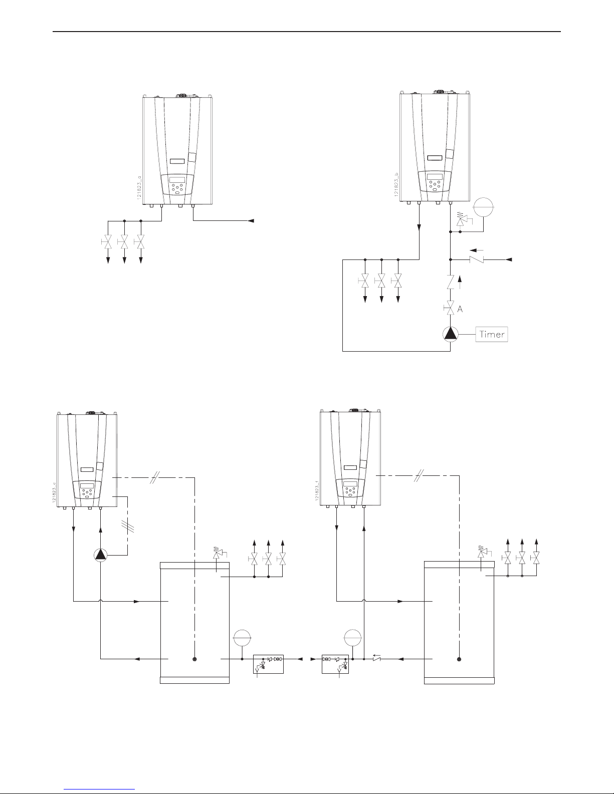
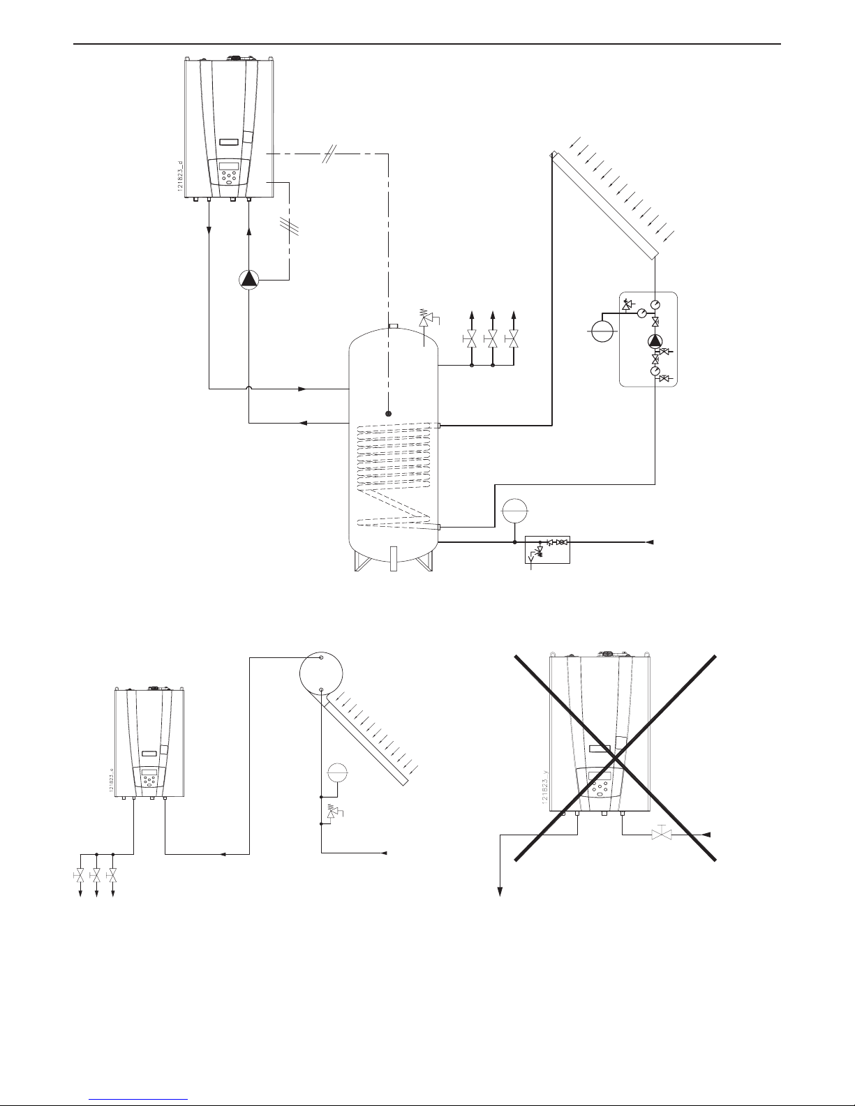
In gures 4-3, 4-4, 4-5, 4-6, 4-7 and 4-8 you can see some
examples of correct installation while in gure 4-9 you can
see one example of wrong installation.
Figure 4-3 - Example of basic installation
Figure 4-5 - Example of installation with storage
tank (see section 5.13)
Figure 4-4 - Example of installation with secondary
return performed by an external pump (see
section 5.12)
Figure 4-6 - Example of installation with
storage tank (see section 5.13)
Page 15
15
AGUADENS
COSMOGAS
4 - OPERATION
Figure 4-7 - Example of installation with solar panel and storage tank (see section 5.13)
Figure 4-8 - Example of installation with solar
panel (maximum inlet temperature to the water
heater is 85°C).
Figure 4-9 - Example of wrong installation
Page 16
16
AGUADENS
COSMOGAS
5.1 - Opening the packaging
The appliance is supplied in cardboard packaging. Open
following the instructions given on the aps of the packaging
itself.
5.2 - Dimensions and minimum
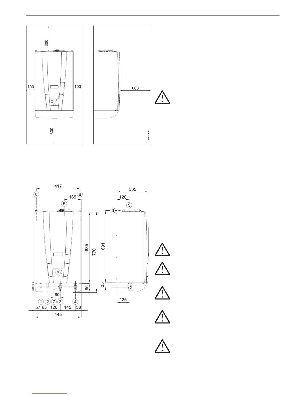
safety clearances
It is necessary to leave free spaces around the appliance as
illustrated in gure 5-1 both for installation and maintenance.
5.3 - Choosing suitable
installation location
ATTENTION !!! The appliance must be installed
exclusively on a solid, vertical wall, which can support
the weight.
The appliance must be installed in a suitable room taking
into account the following factors:
- connection of the exhaust/air intake pipes;
- connection of the gas supply pipe;
- connection to the cold water supply;
- connection of the domestic hot water supply;
- electrical connection;
- connection of the siphon and safety valve to a suitable
drain;
5.4 - Mounting the appliance
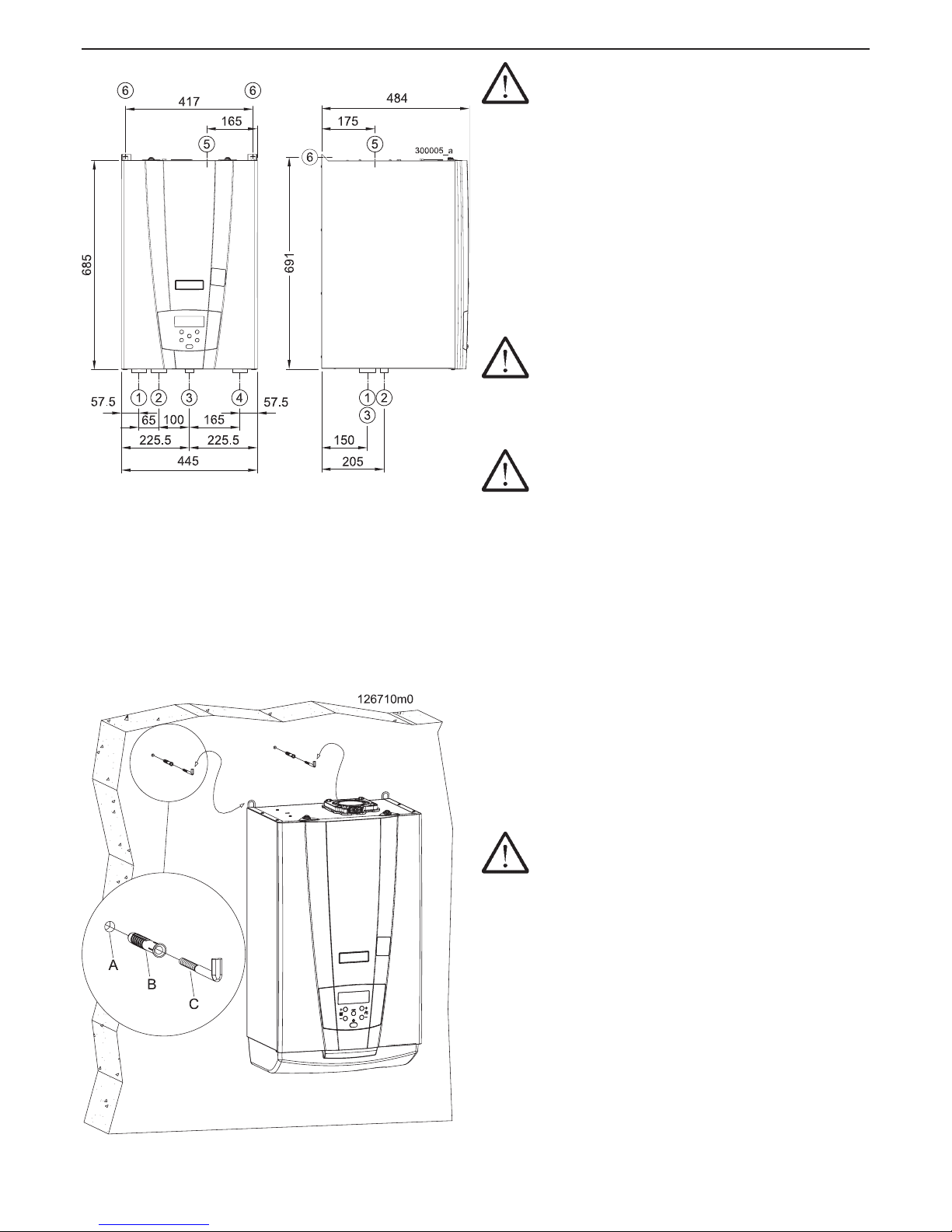
Refer to gure 5-4:
1.- place the paper template, provided with the appliance,
against the wall;
2.- check that the template is square;
3.- mark the holes for the plugs and hydraulic ttings on the
wall;
4.- remove the paper template;
5.- make the holes “A” and introduce the wall plugs “B”;
6.- hang the appliance on the plugs “C”
7.- make the appliance hydraulic and gas connections;
8.- make the hydraulic ttings.
5.5 - Domestic hot and cold water
CAUTION !!! water quality must be within
6,5<pH<8,5 acidity value.
CAUTION !!! If water hardness exceeds 20°f (200
mg/l or 11,2°dH) a water softner must be installed on
the incoming cold water supply.
CAUTION !!! If water heater works at
temperature higher than 60°C and until 75°C, water
hardness must be lower than 15°f (150 mg/l or 8,4°dH)
CAUTION !!! Water hardness must not be
reduced lower than 5°f (50mg/l or 2,8°dH). Softened
water than 5°f (50mg/l or 2,8°dH) is aggressive and can
corrode the heat exchanger reducing life expectation.
CAUTION !!! Install a lter with mesh no wider
than 0.5 mm² in the domestic cold water inlet.
1 - 3/4” recirculation
2 - 1” D.H.W. outlet
3 - 3/4” gas inlet
4 - 3/4” cold water inlet
5 - Fumes exhaust/Air intake
6 - Support attachments
7 - Ø20 condensate drain
5 - INSTALLATION
Figure 5-1 - Minimum safety distances
Figure 5-2 - Dimensions and attachments centre to
centre distances AGUADENS 16 and 22
Page 17
17
AGUADENS
COSMOGAS
5 - INSTALLATION
CAUTION !!!
This water heater can supply water
at a temperature up to 95°C (setup of the safety high limit
thermostat) and pressure of 10 bar (maximum setup of the
relief valve). If the hot water system is built with materials not
able to resist to this temperature and pressure, contractor
must supply and install a device that will shut-off the
appliance before the system material’s maximum operating
temperature and pressure are met.
In gures 5-2 and 5-3 the service and maintenance valves
are not shown. Hydraulic and gas connections should
be tted with isolation valves to accomadate service and
maintenance works.
5.6 - Gas
ATTENTION !!! It is prohibited to operate the
appliance with the incorrect gas type. Ceck the data
label on the appliance for Natural gas (G20) or Propane
gas (G31) to ensure that the correct appliance in being
installed.
ATTENTION !!! Check that the gas and supply
pressure are those for which the appliance has been
adjusted.
Two situations are possible:
A - the gas and supply pressure correspond to the
adjustment of the appliance. In this case, it can be
connected;
B - the gas and supply pressure do not correspond to the
adjustment of the appliance. In this case, the appliance
must be converted to the type of gas and supply
pressure corresponding to those of the supply available.
The appliance is provided with the relevant gas conversion
kit.
Before the gas pipes are purged it is essential to ensure
that the internal surfaces are clean and free of metal or
plastic lings or any other solid pieces or liquids;
An isolation valve must be installed on the gas supply
pipe adjacent to the appliance;
ATTENTION !!! Before supplying gas to the
appliance, it is essential that the gas pipes have been
pressure tested in accordance with the most recent
applicable gas standards.
to prevent damage to the appliance gas valve, the
supply pressure should not exceed 50 mbar under any
circumstances;
if the gas pipe-work must be tested in excess of 50
mbar, ensure that the appliance is fully isolated.
Figures 5-2 and 5-3 shows the position and the diameter of
the gas connection on the appliance. Ensure that the gas
service pipe-work is adequately sized to provide the maximum
volume ow rate at the required minimum pressure.
Figure 5-4 - Appliance wall xing detail
1 - 3/4” secondary return
2 - 1” D.H.W. outlet
3 - 3/4” gas inlet
4 - 1” cold water inlet
5 - Fumes exhaust/Air intake
6 - Support attachments
Figure 5-3 - Dimensions and attachments
centre to centre distances AGUADENS 37
Page 18
18
AGUADENS
COSMOGAS
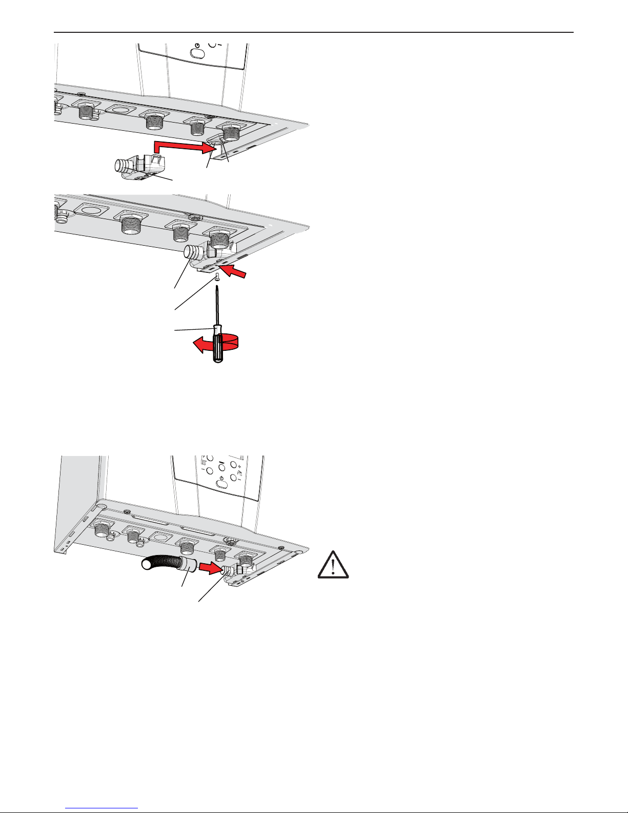
Figure 5-5 - Safety valve drain and condensate
drain connection
B
C
A
020002.01.005
D
A
E
020002.01.006
5 - INSTALLATION
5.7 - Condensate drain
There is a siphon inside the appliance for the evacuation
of condensate (see gures 3-2 and 3-4 detail “40”) and to
prevent combustion products from escaping, whose end
corresponds to the pipe “B” in gure 5-5. This termination
must be conveyed into an anti-odour siphon (gure
5-9 detail “G”) to prevent bad odours returning into the
environment (the anti-odour siphon “G” is supplied on
request). The tank “A” is mounted in the factory as indicated
in gure 5-5, the exhaust pipe “F” is mounted in the factory
as indicated in gure 5-6. In particular, the condensate
discharge must comply with the following:
for room used for residential purposes and for ofce
with more than 10 users, it can be connected to the
domestic waste disposal plant by means of appropriate
siphon with disjunction capable of preventing the
pressurisation of the system (siphon prepared within
appliance) and to prevent the return of bad odours
from the sewer (detail “G” in gure 5-9). If the room
used for ofce purposes has less than 10 users, before
connection with the domestic waste drain, a condensate
neutraliser is good practice (see section 9 for the value of
acidity of the condensate and the quantities).
be connected to a plastic (not copper) drain pipe with a
minimum internal pipe diameter equal to or greater than
13 mm;
be installed in a way to prevent the liquid from freezing;
therefore pay attention to any external passings. It is
prohibited to drain into gutters or drainpipes;
to slope continuously towards the drain point, avoid high
points, which could pressurise the pipe;
5.8 - Safety valve
The appliance is protected against overpressures by a
safety valve calibrated to 10 bar (see gures 3-1 and 3-4
detail “28”). The safety valve drain (detail “C” in gure
5-5), along with the condensate drain (detail “B” in gure
5-5) must be conveyed to a pipe “F” (see gure 5-6) with
minimum internal diameter of 13 mm. The pipe “F” must be
then taken to the anti-odour siphon (detail “G” gure 5-9).
This drain with siphon is used to prevent overpressures if
the valve is opened and makes it possible for the user to
check the eventual intervention. The pipe “F” in gure 5-6
is supplied by standard along with the tank “A” in gure
5-5. The anti-odour siphon “G” in gure 5-9 is provided on
request.
ATTENTION !!! If not connected to the drain,
whenever the safety valve should intervene, it could
cause damage to persons, animals or objects.
Figure 5-6 - Condensate drain pipe
A
F
020002.01.017
Page 19
19
AGUADENS
COSMOGAS
5 - INSTALLATION
5.9 - Hydraulic and gas connections
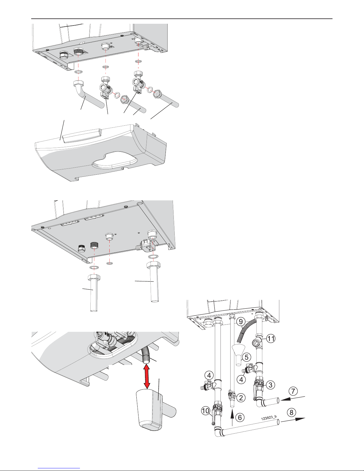
The appliance models AGUADENS 16 and 22 is supplied
as per standard with the ttings illustrated in gure 5-7,
where:
A = Ø 18 recirculation
B = domestic hot water Ø 22
C = 3/4” gas isolation valve (EN 331 type-approved)
D = 3/4” domestic cold water isolation valve
E = gas Ø 18
F = domestic cold water Ø 18
Once the hydraulic and gas connections have been made,
proceed with assembly of the lower cover “G” as indicated
in gure 5-7.
The appliance models AGUADENS 37 is supplied as per
standard with the ttings illustrated in gure 5-8, where:
M = domestic hot water Ø 22
N = domestic cold water Ø 22
5.10 - Water softener (on request)
If the appliance is installed in a geographical area where
domestic water has hardness exceeding 20°F (200 mg/l), a
polyphosphates softener must be installed on the cold water
supply, in order to safeguard the appliance from any lime
scale deposits.
Figure 5-7 - Water and gas connections
AGUADENS 16 and 22
E
F
B
C
DGE
F
B
C
D
G
020003.01.056
Figure 5-9 - F = condensing drain pipe
G = siphon funnel (on request)
F
G
020002.01.028
min10 mm
max 30 mm
Figure 5-8 - Water and gas connections
AGUADENS 37
MNM
N
020008.01.018
Figure 5-10 - Typical piping
Legenda di gura 5-10:
2 = Gas manual valve (EN 331 type-approved) (Field
supplied)
3 = Water isolation valve / Flow rate selector (Field
supplied)
4 = Water drain valve (Field supplied)
5 = Condensate drain (Field supplied)
6 = Gas inlet
7 = Cold water supply
8 = Domestic hot water
9 = Condensate drain pipe
10 = Water isolation valve (Field supplied)
11 = Filter (Field supplied)
Page 20
20
AGUADENS
COSMOGAS
5.11 - Electrical connections
ATTENTION !!! The appliance is only electrically
safe when it has been correctly connected to an
efcient earth circuit, performed as envisioned by the
current Safety Standards.
This fundamental safety requirement must be met. If in
doubt, request a thorough control of the electric plant by a
professionally qualied technician.
Have a professionally qualied technician check that the
electric plant is suitable for the electric power required by
the appliance, indicated on the plate.
The appliance must be connected to the mains electricity
using a cable coupler. The use of adapters, multiple
sockets, extensions, etc. is not allowed.
The appliance must be connected to the mains electricity
using a three-polar electric cable, with double isolation,
minimum section of 1,5 mm² and resistant to a minimum
temperature of 70°C (characteristic T).
For connection to mains electricity, a bi-polar switch
must be envisioned in the vicinity of the appliance with a
contacts opening distance of at least 3mm, as envisioned
by the current regulations on the subject.
Respect the polarity between the neutral phase during
connection of the appliance.
Make sure that the water plant pipes are not used as
earth points for the electric or telephone plant. This
piping is not suitable for this purpose, moreover, serious
corrosion damage would occur in a very short time, on
the appliance, piping and radiators.
ATTENTION !!! the appliance is not protected
against the effects caused by lightening.
D
C
C
C
B
A
020003.01.009
5 - INSTALLATION
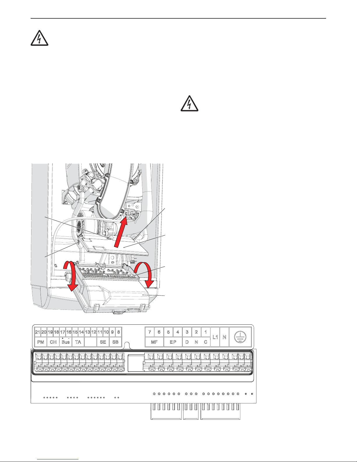
Figure 5-11 - Electric connections
Key for gure 5-11
A = Commands board box;
B = Electric connections board lid;
C = Connections lid closing aps;
D = Electric connections board;
Key for electric contacts
PM = Not used
CH = Not used
BUS = Not used
TA = CR04 remote time control (if present)
SE = Not used
SB = Storage tank sensor (if present)
MF = Multi-function output
EP = Boiler pump (if present)
DN = Not used
(2 = Neutral; 3 = Line)
L1 = Appliance power supply line
N = Appliance power supply neutral
EARTH SYMBOL = Earth contacts
020002.01.010
62408190
Page 21
21
AGUADENS
COSMOGAS
5.11.1 - Power supply cable connection
Proceed as follows to connect the power supply cable (refer
to gure 5-11):
1.- use a three-polar cable with double isolation, with
minimum section of 1,5 mm²
2.- remove the casing from the appliance following the
relevant instructions in section 8.2;
3.- rotate the panel “A” towards the front of the appliance;
4.- operate on the aps “C” and open the lid “B” as
indicated by the arrow;
5.- lay the power supply cable through the fairlead in
proximity of the contacts “L1”, “N” and earth symbol;
6.- strip the cable, making sure to keep the earth cable
(yellow green) 20 mm longer than the other two;
7.- connect the yellow-green cable to the earth terminals
(see symbol)
8.- connect the brown cable (Phase) to the terminals L1
9.- connect the blue cable (Neutral) to the terminals N
5 - INSTALLATION
5.11.2 - CR04 remote Time control (on
request)
The CR04 remote time control is able to interact with the
appliance.
Proceed as follow for the electric (refer to the gure 5-11):
lay a bi-polar electric cable with minimum section of
1,5 mm², from the appliance to the CR04 remote time
control. The cable must also be shielded. Shield must
be connected to the earth from the side of the appliance.
The maximum length permitted is 100 metres;
remove the casing and access to the junction box (see
section 8.2);
connect the cable to the terminals “14” and “15” of the
appliance (see gure 5-11 “TA”).
connect the other side of the cable to the CR04 remote
time control terminals (follow the CR04 instruction
manual).
ATTENTION !!!
Since the cables of the remote control are subject to
extremely low security voltage (24Vcc), they must pass
through ducts different from the 230Vac supply cables.
Once the remote control has been connected, all the room
temperature adjustments and domestic water temperature
operations must be carried out directly on the same.
Accordingly, remember to closely follow the instructions
contained on the CR04 remote control.
Page 22

22
AGUADENS
COSMOGAS
5.12 - External secondary
return conguration
if the appliance is envisioned with secondary recirculation
(see gure 4-5), operate as follow:
1.- install the appliance as shown in gure 4-5;
2.- open one tap of the sanitary utilities to eliminate
presence of air;
3.- turn off the secondary return pump;
4.- open one hot water sanitary tap and wait until the hot
water temperature is stable;
5.- close the hot water sanitary tap;
6.- check that after 50 seconds after closing the tap, tap
icon on the display has stopped ashing;
7.- if the tap icon keeps ashing, it means that the internal
pump can run the water in the secondary return circuit to
a value above 2 l/min (veriable on the parameter 1062).
8.- operate on the valve “A” of Figure 4-4 in order to bring
the recirculation ow rate to a value lower than 2 l/min;
9.- now the appliance can work correctly.
Page 23
23
AGUADENS
COSMOGAS
5 - INSTALLATION
5.13 - Connection water
heater to Storage tank
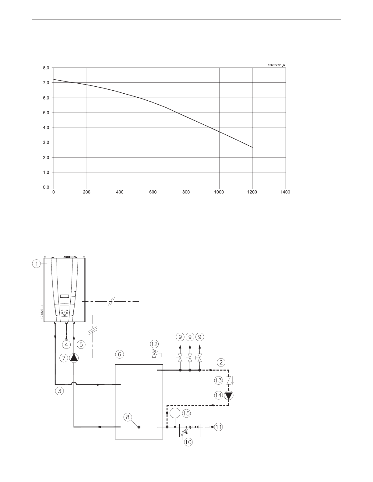
If the storage tank is charged with internal pump (gure
4-7), must consider the residual head of gure 5-13 to size
the system.
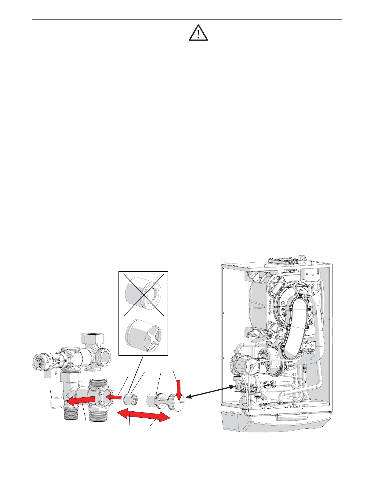
When the water heater is envisioned with storage tank, as
shown in gure 4-7, before connect must be inserted into
the appliance the by-pass valve “C” as shown in gure
5-12. Otherwise, if the storage tank is charged with external
pump (see gure 4-6, 4-8 and 5-14), it is not necessary to
insert the valve “C”.
Proceed as follows for the electric connection (refer to the
gure 5-11):
1.- disconnect the electric power supply from the appliance;
2.- disconnect the wire from the sensor detail “46” of gures
3-1 or 3-3;
3.- lay a bi-polar electric cable with minimum section of 1,5
mm2, which goes from the appliance tothe storage tank
temperature sensor and connect it to the appliance at
terminals “8” and “9” (SB);
4.- connect the other end of the cable to the storage tank
temperature sensor;
5.- introduce the temperature sensor inside the storage tank
sample point (see gure 5-14 detail “8”).
6.- connect the electric power of the storage tank pump to
“EP” terminals of the water heater.
7.- set the parameters 3012 = 1 and 3041 = 15.
the water temperature stored inside the storage tank can be
chosen by the user in a range between 40 and 60°C.
ATTENTION !!! A domestic hot water
temperature level exceeding 51°C can cause permanent
injury/damage to persons, animals and objects.
Children, the elderly and disabled must be protected
against the potential risks of scalding, by introducing
devices that limit the temperature of use of domestic
hot water to utilities.
5.13.1 - Anti- legionella precaution
If the appliance is connected to a storage tank for the
preparation of domestic hot water, a disinfection cycle is
envisioned against the legionella bacterium. This cycle
envisions taking the storage tank to a temperature of 60°C
(temperature at which the legionella bacteria dies) at least
every week. It is for this reason that the water (at certain
times) can reach the utilities at a higher temperature that
than set with the relative command.
Figure 5-12 - bypass valve “C” to be included in case of installation with storage tank (respect the
direction of the valve).
020003.01.048
5
B
4
C
1
3
A
2
5
B
4
C
1
3
A
2
020008.01.017
020008.01.021
Page 24
24
AGUADENS
COSMOGAS
5 - INSTALLATION
Figure 5-14 - hydraulic connection to storage tank
KEY
1 AGUADENS water heater
2 Recirculation (if activated) *
3 Domestic hot water outlet
4 Gas inlet
5 Cold water
6 Storage tank
7 Storage tank load pump
8 Storage tank sensor
9 Domestic utilities
10 Hydraulic safety unit (by the installer)
11 Cold water inlet
12 So me state re quir e thi s safe ty
pressure-temperature relief valve
13 Non-return valve
14 Recirculation pump (if present)
* The recirculation line is not mandatory.
Figure 5-13 - Curve of residual pressure for the storage tank charging
with internal pump (see gure 4-7)
Prevalenza residua (mH2O)
Portata acqua (l/h)
Page 25
25
AGUADENS
COSMOGAS
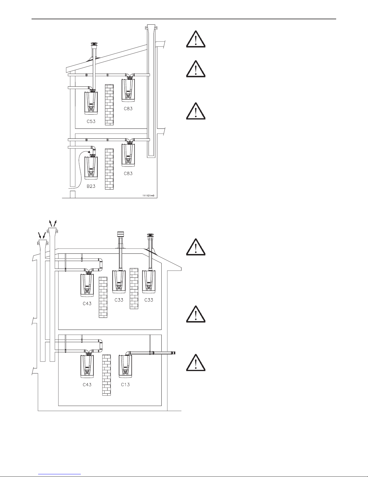
5.14 - Flue systems
ATTENTION !!! The relevant national and local
regulations must be strictly adhered to when installing
the exhaust ue and combustion air pipes.
ATTENTION !!! The exhaust ue gases from
the appliance can reach 90°C in certain conditions.
Therefore, the plastic ue components must be capable
of withstanding high temperatures and they must be
approved for these specic appliance.
ATTENTION !!! This appliance is the
“condensing” type. The polypropylene materials used
in the manufacture of plastic exhaust ue system
which are approved for use are designed to prevent
corrosion which would otherwise be caused to the
acidity of the condensate. AISI316 stainless steel
exhaust ue system can also be designed for this
purpose.
Regarding this, remember that the appliances of this
type must have exhaust and intake pipes supplied by the
manufacturer of the appliance itself. Other types of pipes,
if used, must however be type-approved for this intended
use. The types of exhaust for which the appliance is
approved are given in the features table at the end of the
manual under “type” and o the features plate afxed to the
appliance, also under “type”. The symbols used to dene
exhaust is reported below:
- B23, separated with intake in room and exhaust through
wall or roof.
ATTENTION !!! If the appliance is installed with the
B23 type exhaust, it will take in air for combustion from
the surrounding environment. Therefore, all precautions
must be taken regarding ventilation of the rooms, which
are prescribed by the national and/or local Standards.
- C13, coaxial in vertical wall
- C33, coaxial at the roof
- C43, separated with exhaust in ue, combined with intake
in common channel.
ATTENTION !!! The appliances installed in type
C43 must only be connected to conventional ues.
- C53, separated with exhaust on roof and intake on wall or
however, in two potentially different pressure points.
- C63, the appliance can be tted to type-approved exhaust
and intake pipes of other brands.
ATTENTION !!! With the C63 type exhaust,
the condensate coming from the chimney cannot be
conveyed into the appliance.
- C83, separated with wall intake or another point
independent from the intakes of other appliances and
ue exhaust.
Figure 5-15 - Exhaust/intake systems
5 - INSTALLATION
Page 26

26
AGUADENS
COSMOGAS
During operation, especially in winter, a plume will be
visible as the water vapour in the exhaust gases come into
contact with the outside air. This plume should not cause
any concern however the installer should discuss the matter
with the customer prior to commencement of the installation
in case the aesthetical impact of this plume might cause a
problem.
5.14.1 - Exhaust ue with indipendent
combustion air grille type B23
In the case of B23 type combustion agent air/fumes exhaust
systems, it is indispensable that the rooms in which the
appliances are installed have at least as much air as that
required by combustion and ventilation of the room. It is
therefore good practice to remember that the combustion of
1 m³ of gas requires 11 cm³ of air. The natural ow of air must
take place directly through permanent openings made in the
outside walls of the room to be ventilated; however away from
sources of pollution, such as: vents of dubious origin, airborne
industrial exhaust etc.
The ventilation openings must meet the following requirements:
have sections with net passage of at least 6 cm² for
every kW of heat input installed, with minimum of 100
cm²;
be realised in a way that the opening inlets both inside
and outside the wall cannot be blocked;
be protected for example with grids, metal meshes, etc.
The net section of the passage must not be reduced by
these elements;
be situated at a height more or less of the oor and such
not to disturb the correct operation of the combustion
products exhaust devices. Where this position is not
possible, the section of the ventilation openings must be
increased by at least 50%.
The ow of air can also be obtained from an adjacent room
as long as:
it has direct ventilation, in compliance with the previous
points;
only this gas appliance is installed in the room to be
ventilated;
the adjacent room is not a bedroom;
the adjacent room is not a common part of the building;
the adjacent room is not an environment with re hazard,
such as a hangars, garages, combustible materials
warehouse, etc.;
the adjacent room does not have a negative pressure with
respect to the room to be ventilated due to reverse draught
(which can be caused by the presence in the room of
another appliance operating with any type of fuel, a replace
and any other intake device for which an adequate air intake
has not been envisioned);
the ow of air from the adjacent room to that to be ventilated
can take place freely through permanent openings with
total net section not less than that indicated at the start of
this section.
In rooms where gas appliances are installed, it may become
necessary, as well as the input of combustion agent air, also
to evacuate the stale air, with resulting release of an additional
equal amount of clean air.
If the stale air is evacuated with the aid of a mechanical tool
(electric fan) the following conditions must be respected:
a) If there is a common exhaust pipe in the room, it must be
capped;
b) The ventilation opening of the room in which the gas
appliance is installed must be increased depending on the
maximum air ow rate required at the electric fan.
c) The action of the electric fan must not affect the correct
evacuation of the combustion products. To this end, that
stated above must be veried by draft testing, running the
fan or extractor hood at its maximum power and the gas
appliance at the maximum and minimum power.
5 - INSTALLATION
Page 27
27
AGUADENS
COSMOGAS
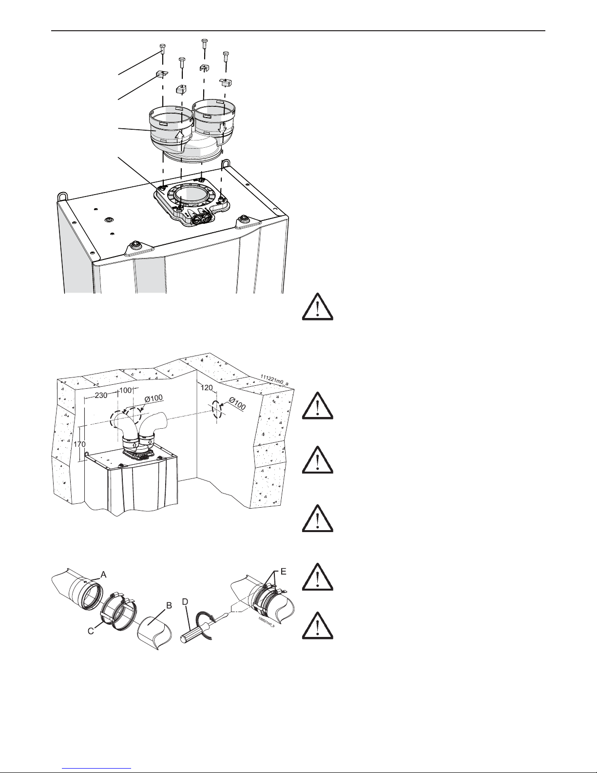
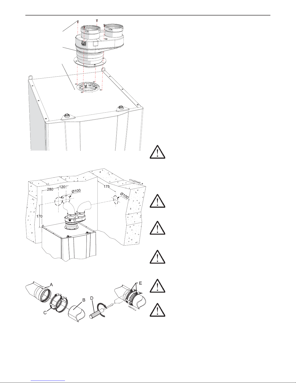
5.14.2 - “Split 80/80PP” System
(polypropylene) (Type C43; C53; C83)
AGUADENS 16 and 22
The appliance is supplied as per standard without ttings
for the connection of the fumes exhaust/air intake. To
connect it to a “80/80PP Split” system, the relevant kit must
be requested and must be installed as in gure 5-16.
Fitting “A” can rotate freely by 360°, guaranteeing optimum
installation versatility.
On the exhaust ue side, it is mandatory to install
polypropylene plastic pipes or AISI 316L stainless steel
which are resistant to damage from condensation.
Take particular care with the installation of pipes in
the part that passes through the wall to the outside.
The normal maintenance operations must always be
possible, therefore install the pipes in a sheath so that
they can slide out.
The horizontal exhaust ue pipes must always have
an inclination of 2% with the fall back towards the
appliances as opposed to the wall terminal.
The appliance is already set-up to collect the
condensate, which must be tted to a drain pipe (see
section 5.7).
ATTENTION !!! This condensate drain is
designed to make all liquid produced ow from a single
appliance. If several appliances are installed, each one
must envision its own condensate drain.
The fumes exhaust/air intake system can be extended up
to a maximum distance as indicated in section 9. Every 90°
bend has a loss equivalent to value on section 9. Every 45°
bend has a loss equivalent to value on section 9.
ATTENTION !!! The exhaust ue terminal must
be appropriately protected against the effects of the
wind (see also 7.9.1 error Loc 20).
ATTENTION !!! Mechanically secure the joints
between the various component elements of the
exhaust and intake pipe, through the use of xing
systems or equivalent systems. See gure 5-18.
ATTENTION !!! The temperature of the exhaust
pipe can reach 90°C during operations. If it must pass
through a wall that is sensitive to these temperatures,
insert a protective heat-isolation sheath.
ATTENTION !!! If the air intake and fumes
exhaust terminals are positioned in the same wall, they
must remain at a minimum distance of 1 metre.
ATTENTION !!! The exhaust and intake pipes
must be appropriately sustained via rigid brackets
positioned no more than 1 metre from each other. The
brackets must be xed to rigid walls that can support
the weight of the pipe itself.
Figure 5-18 - Fixing the exhaust and intake pipes
Figure 5-16 - Installation of the “80/80PP Split”
System
Figure 5-17 - Clearance
5 - INSTALLATION
B
D
A
C
020002.01.011
Page 28
28
AGUADENS
COSMOGAS
5.14.3 - “Split 80/80PP” System
(polypropylene) (Type C43; C53; C83)
AGUADENS 37
The appliance is supplied as per standard without ttings
for the connection of the fumes exhaust/air intake. To
connect it to a “80/80PP Split” system, the relevant kit must
be requested and must be installed as in gure 5-19.
Fitting “A” can rotate freely by 360°, guaranteeing optimum
installation versatility.
On the exhaust ue side, it is mandatory to install
polypropylene plastic pipes or AISI 316L stainless steel
which are resistant to damage from condensation.
Take particular care with the installation of pipes in
the part that passes through the wall to the outside.
The normal maintenance operations must always be
possible, therefore install the pipes in a sheath so that
they can be slid out.
The horizontal exhaust ue pipes must always have an
inclination of 2% with the fall back towards the appliance
as opposed to the wall terminal.
The appliance is already set-up to collect the
condensate, which must be tted to a drain pipe (see
section 5.7).
ATTENTION !!! This condensate drain is
designed to make all liquid produced ow from a single
appliance. If several appliances are installed, each one
must envision its own condensate drain.
The fumes exhaust/air intake system can be extended up
to a maximum distance as indicated in section 9. Every 90°
bend has a loss equivalent to value on section 9. Every 45°
bend has a loss equivalent to value on section 9.
ATTENTION !!! The exhaust ue terminal must
be appropriately protected against the effects of the
wind (see also 7.9.1 error Loc 20).
ATTENTION !!! Mechanically secure the joints
between the various component elements of the
exhaust and intake pipe, through the use of xing
systems or equivalent systems. See gure 5-21.
ATTENTION !!! The temperature of the exhaust
pipe can reach 90°C during operations. If it must pass
through a wall that is sensitive to these temperatures,
insert a protective heat-isolation sheath.
ATTENTION !!! If the air intake and fumes
exhaust terminals are positioned in the same wall, they
must remain at a minimum distance of 1 metre.
ATTENTION !!! The exhaust and intake pipes
must be appropriately sustained via rigid brackets
positioned no more than 1 metre from each other. The
brackets must be xed to rigid walls that can support
the weight of the pipe itself.
Figure 5-21 - Fixing the exhaust and intake pipes
Figure 5-19 - Installation of the “80/80PP Split”
System
Figure 5-20 - Clearance
5 - INSTALLATION
B
C
A
020008.01.011
Page 29
29
AGUADENS
COSMOGAS
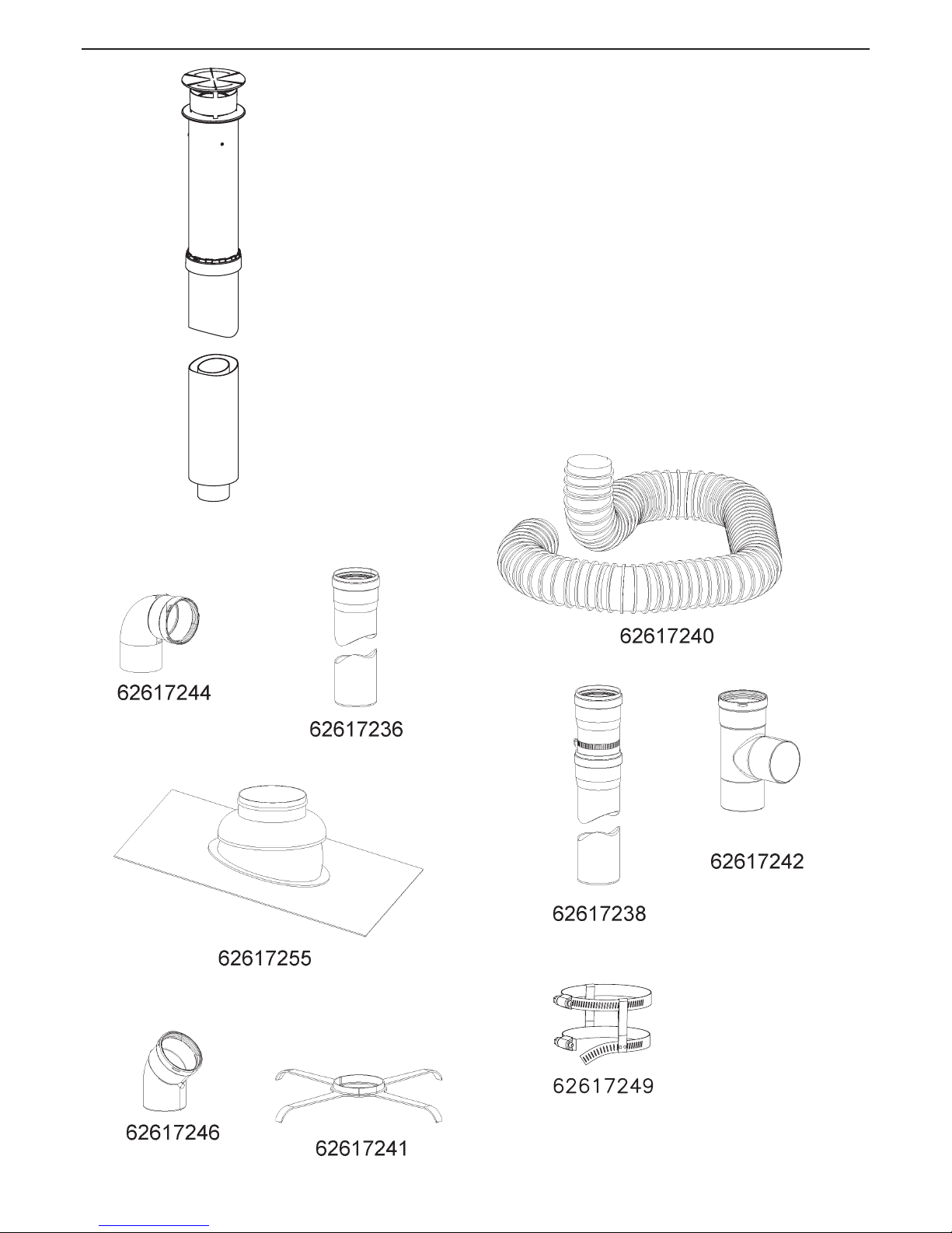
5.14.4 - “Split 80/80PP” System (Type C43;
C53; C83): accessories available
To make the “80/80PP split” fumes exhaust/air intake system,
we propose some of the most common accessories available;
remember that a wide range can be consulted in the relevant
catalogue: (the number after the code is used to recall the
piece in the following drawings)
62617306 - N° 10 PP roof terminal
62617244 - N° 12 90° bend M/F PP
62617255 - N° 29 converts for pitched roofs from 15° up to 25°
62617236 - N° 11 extension M/F PP
62617249 - N°18 anti-slip bands for extensions PP
62617240 - N° 14 exible hose M.F. PP L=20m
62617241 - N°16 spacer for exible hose
62617238 - N° 17 telescopic joint PP
62617242 - N° 15 T-tting PP
62617246 - N° 13 45° bend M/F PP
62617306
5 - INSTALLATION
Page 30
30
AGUADENS
COSMOGAS
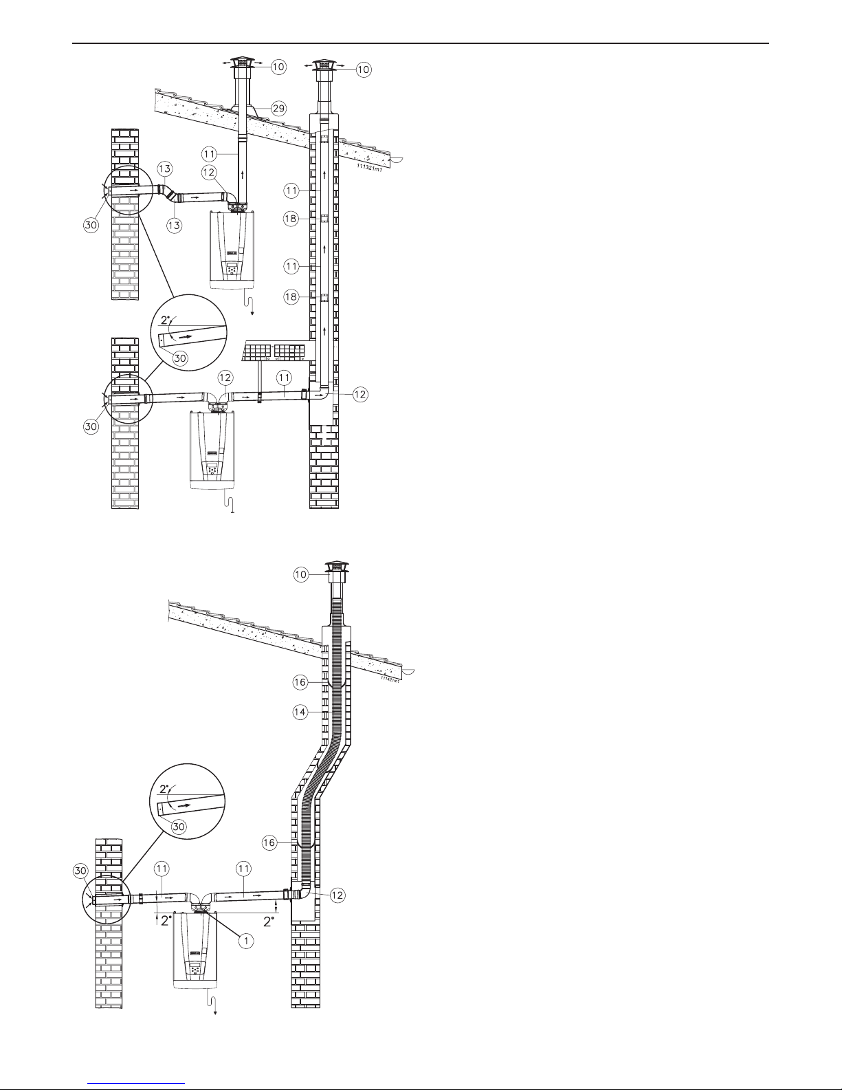
5.14.5 - “Split 80/80PP” System (Type C43;
C53; C83): installation examples
In gure 5-22 two examples of installation are given:
- exhaust into chimney with collection of condensate inside
the appliance itself.
The horizontal part of the fumes exhaust must slope towards
the appliance.
The intake must slope towards the outside to prevent rain
water entering.
- exhaust to the outside directly with the appliance pipes with
condensate collection inside the appliance itself.
The intake must slope towards the outside to prevent rain
water entering.
Figure 5-22 - Example of “80/80 PP System”
installation
Figure 5-23 - Example of “80/80 PP System” installation
5 - INSTALLATION
In gure 5-23 it is possible to see a separated type of fumes
exhaust, where fumes exhaust was realised with exible hose
in polypropylene for piping of technical cells.
The condensate produced in the vertical pipe must all be
conveyed into the appliance.
The intake must slope towards the outside to prevent rain
water entering.
Page 31
31
AGUADENS
COSMOGAS
B
D
A
C
020002.01.012
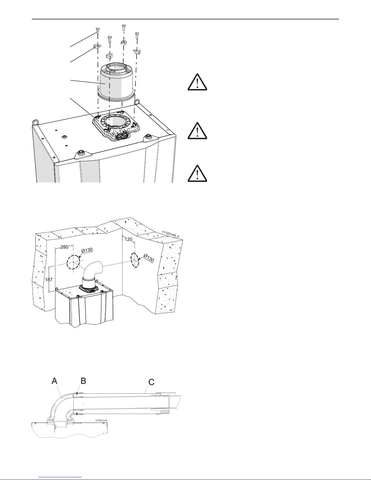
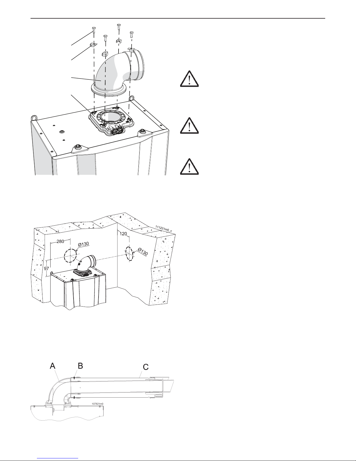
5.14.6 - “60/100PP vertical coaxial” System
(polypropylene) (C13; C33 Type)
AGUADENS 16 and 22
The appliance is supplied as per standard without ttings
for the connection of the fumes exhaust/air intake. To
connect it to a vertical 60/100 system, the relevant kit must
be requested and must be installed as in gure 5-24.
ATTENTION !!! Scrupulously follow the installation
phases of the coaxial pipe as illustrated in gure 5-26. In
particular:
1.- introduce the coaxial pipe “C” inside the bend “A”;
2.- x the external pipe using the stainless steel self-threading
screws “B”.
ATTENTION !!! The coaxial exhaust and
intake pipes must be appropriately sustained via rigid
brackets positioned no more than 1 metre from each
other. The brackets must be xed to rigid walls that can
support the weight of the pipe itself.
ATTENTION !!! Once these operations have
been performed, check that the exhaust/intake terminal
is exposed to the outdoors with the tolerances given in
gure 5-30.
Take particular care with the installation of pipes in the part
that passes through the wall to the outside. The normal
maintenance operations must always be possible, therefore
install the pipes in a sheath so that they can slide out.
The horizontal exhaust ue pipes must always have an
inclination of 2% with the fall back towards the appliances
as opposed to the wall terminal.
The combined exhaust/air intake pipe can be extended up
to a maximum distance as indicated in the table in section
9 at the end of the manual. Every 90° bend has a loss
equivalent to value on section 9. Every 45° bend has a loss
equivalent to value on section 9.
Figure 5-24 - Installation of vertical coaxial system
Figure 5-25 - Quotes and hole centre to centre
distances for coaxial drain pre-installation
Figure 5-26 - Positioning the coaxial pipe
5 - INSTALLATION
Page 32
32
AGUADENS
COSMOGAS
Figure 5-28 - Quotes and hole centre to centre
distances for coaxial drain pre-installation
5 - INSTALLATION
Figure 5-29 - Positioning the coaxial pipe
5.14.7 - “60/100PP horizontal coaxial”
System (polypropylene) (C13; C33 Type)
AGUADENS 16 and 22
The appliance is supplied as per standard without ttings
for the connection of the fumes exhaust/air intake. To
connect the appliance to a 60/100 coaxial system, request
the relevant kit and install it as in gure 5-27.
ATTENTION !!! Scrupulously follow the installation
phases of the coaxial pipe as illustrated in gure 5-29. In
particular:
1. - introduce the coaxial pipe “C” inside the bend “A”;
2. - x the external pipe using the stainless steel self-threading
screws “B”.
ATTENTION !!!The coaxial exhaust and intake
pipes must be appropriately sustained via rigid
brackets positioned no more than 1 metre from each
other. The brackets must be xed to rigid walls that can
support the weight of the pipe itself.
ATTENTION !!! Once these operations have
been performed, check that the exhaust/intake terminal
is exposed to the outdoors with the tolerances given in
gure 5-30.
Take particular care with the installation of pipes in the part
that passes through the wall to the outside. The normal
maintenance operations must always be possible, therefore
install the pipes in a sheath so that they can be slid out.
The horizontal exhaust ue pipes must always have an
inclination of 2% with the fall back towards the appliances
as opposed to the wall terminal.
The combined exhaust/air intake pipe can be extended up
to a maximum distance as indicated in the table in section
9 at the end of the manual. Every 90° bend has a loss
equivalent to value on section 9. Every 45° bend has a loss
equivalent to value on section 9.
B
D
A
C
020002.01.013
Figure 5-27 - Installation of horizontal coaxial
system
Page 33
33
AGUADENS
COSMOGAS
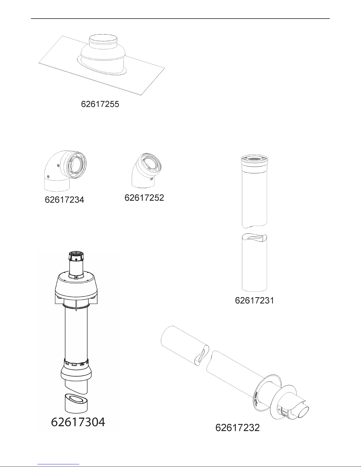
5.14.8 - “60/100PP Coaxial” System:
accessories available
The following accessories are available on request to make
the 60/100 coaxial fumes exhaust/air intake system:
(the number after the code is used to recall the piece in the
following drawings)
62617255 - N° 2 converts for pitched roofs from 5° to 25°
extension L = 1000 mm
62617234 - N° 1 90° coaxial bend M/F PP
62617252 - N° 6 45° coaxial bend M/F PP
62617231 - N° 7 Coaxial extension L 1m PP
62617304 - N° 3 coaxial PP roof terminal
62617232 - N° 5 coaxial PP wall terminal
5 - INSTALLATION
Page 34
34
AGUADENS
COSMOGAS
5 - INSTALLATION
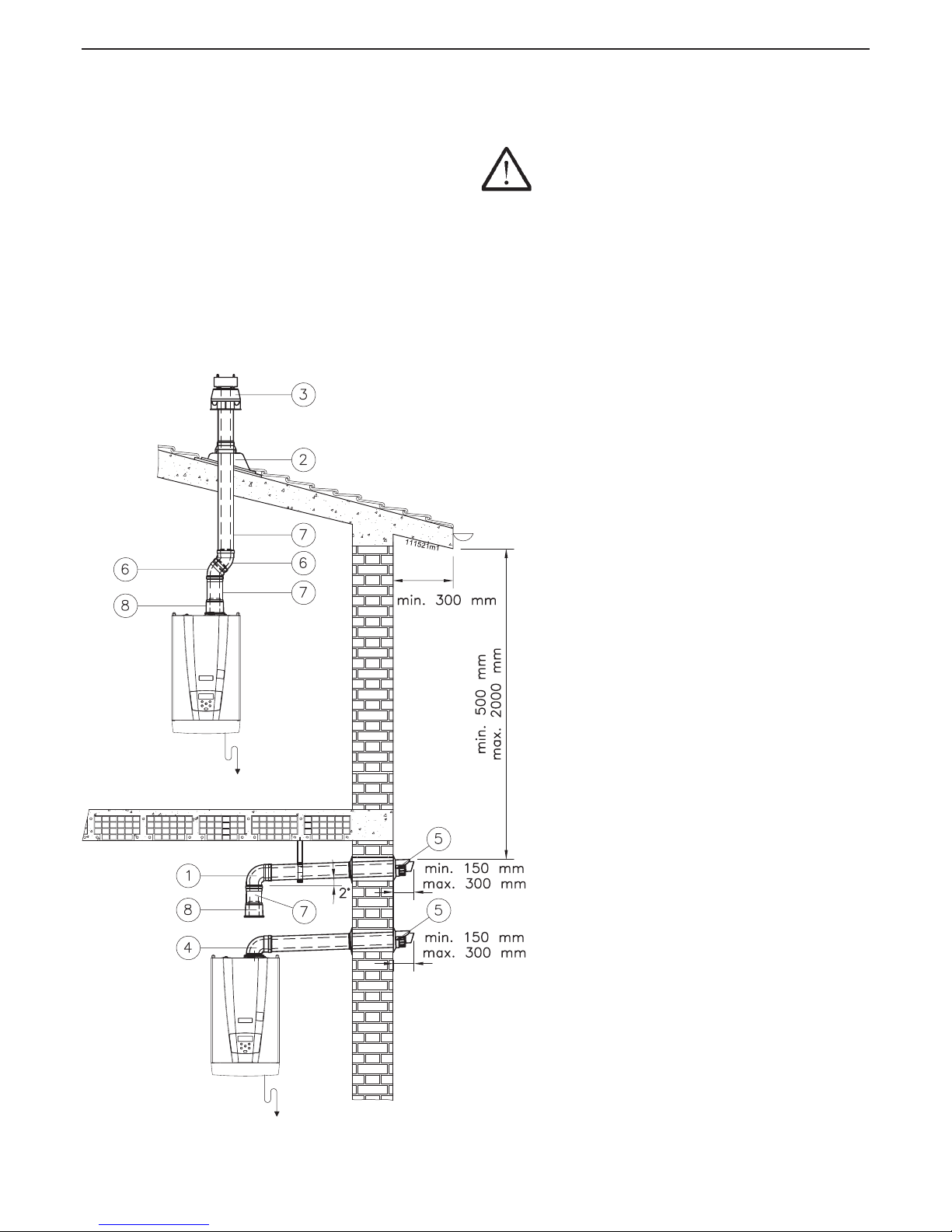
5.14.9 - “60/100PP Coaxial” System:
installation examples
When a coaxial exhaust is made (see gure 5-30), both vertical
and horizontal, the exhaust pipe slope upwards in a way to
make the condensate ow into the appliance.
ATTENTION !!! The horizontal terminal must be
protected against the accidental return of rain water.
To do this, gables must be installed (or projections or
balconies or relevant protections ) with the minimum
dimensions given in gure 5-30
Figure 5-30 - Examples of coaxial pipe
installations
Page 35
35
AGUADENS
COSMOGAS
B
C
A
020008.01.013
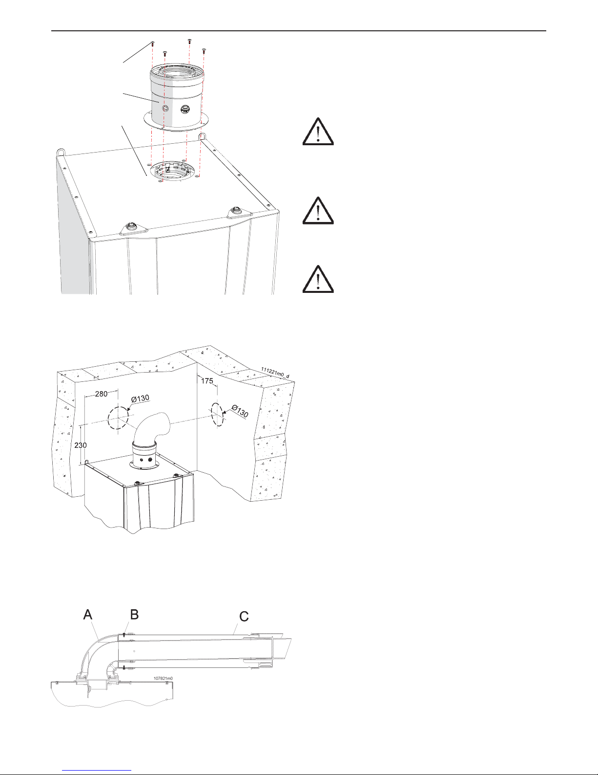
5.14.10 - “80/125PP vertical coaxial”
System (polypropylene) (C13; C33)
AGUADENS 37
The appliance is supplied as per standard without ttings
for the connection of the fumes exhaust/air intake. To
connect it to a vertical 80/125 system, the relevant kit must
be requested and must be installed as in gure 5-31.
ATTENTION !!! Scrupulously follow the installation
phases of the coaxial pipe as illustrated in gure 5-33. In
particular:
1.- introduce the coaxial pipe “C” inside the bend “A”;
2.- x the external pipe using the stainless steel self-threading
screws “B”.
ATTENTION !!! The coaxial exhaust and
intake pipes must be appropriately sustained via rigid
brackets positioned no more than 1 metre from each
other. The brackets must be xed to rigid walls that can
support the weight of the pipe itself.
ATTENTION !!! Once these operations have
been performed, check that the exhaust/intake terminal
is exposed to the outdoors with the tolerances given in
gure 5-34.
Take particular care with the installation of pipes in the
part that passes through the wall to the outside. Normal
maintenance operations must always be possible, therefore
install the pipes in a sheath so that they can slide out.
The horizontal exhaust ue pipes must always have an
inclination of 2% with the fall back towards the appliances
as opposed to the wall terminal.
The combined exhaust/air intake pipe can be extended up
to a maximum distance as indicated in the table in section
9 at the end of the manual. Every 90° bend has a loss
equivalent to value on section 9. Every 45° bend has a loss
equivalent to value on section 9.
Figure 5-31 - Installation of vertical coaxial system
Figure 5-32 - Quotes and hole centre to centre
distances for coaxial drain pre-installation
Figure 5-33 - Positioning the coaxial pipe
5 - INSTALLATION
Page 36
36
AGUADENS
COSMOGAS
5.14.11 - “80/125PP Coaxial” System:
accessories available
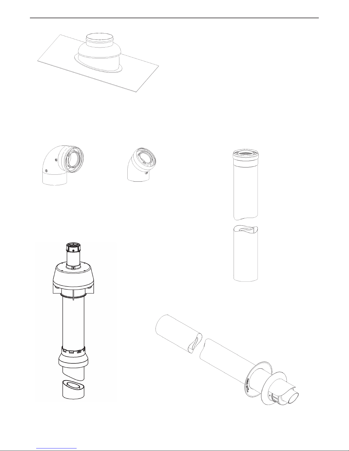
The following accessories are available on request to make
the 80/125 coaxial fumes exhaust/air intake system:
(the number after the code is used to recall the piece in the
following drawings)
62617255 - N° 2 converts for pitched roofs from 5° to 25°
extension L = 1000 mm
62617321 - N° 1 90° coaxial bend M/F PP
62617322 - N° 6 45° coaxial bend M/F PP
62617323 - N° 7 Coaxial extension L 1m PP
62617325 - N° 3 coaxial PP roof terminal
62617324 - N° 5 coaxial PP wall terminal
5 - INSTALLATION
62617255
62617321
62617322
62617323
62617324
62617325
Page 37
37
AGUADENS
COSMOGAS
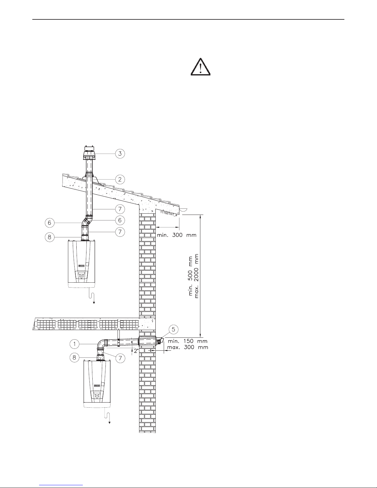
5.14.12 - “80/125PP Coaxial” System:
installation examples
When a coaxial exhaust is made (see gure 5-34), both vertical
and horizontal, the exhaust pipe slope upwards in a way to
make the condensate ow into the appliance.
ATTENTION !!! The horizontal terminal must be
protected against the accidental return of rain water.
To do this, gables must be installed (or projections or
balconies or relevant protections ) with the minimum
dimensions given in gure 5-34.
Figure 5-34 - Examples of coaxial pipe
installations
5 - INSTALLATION
Page 38
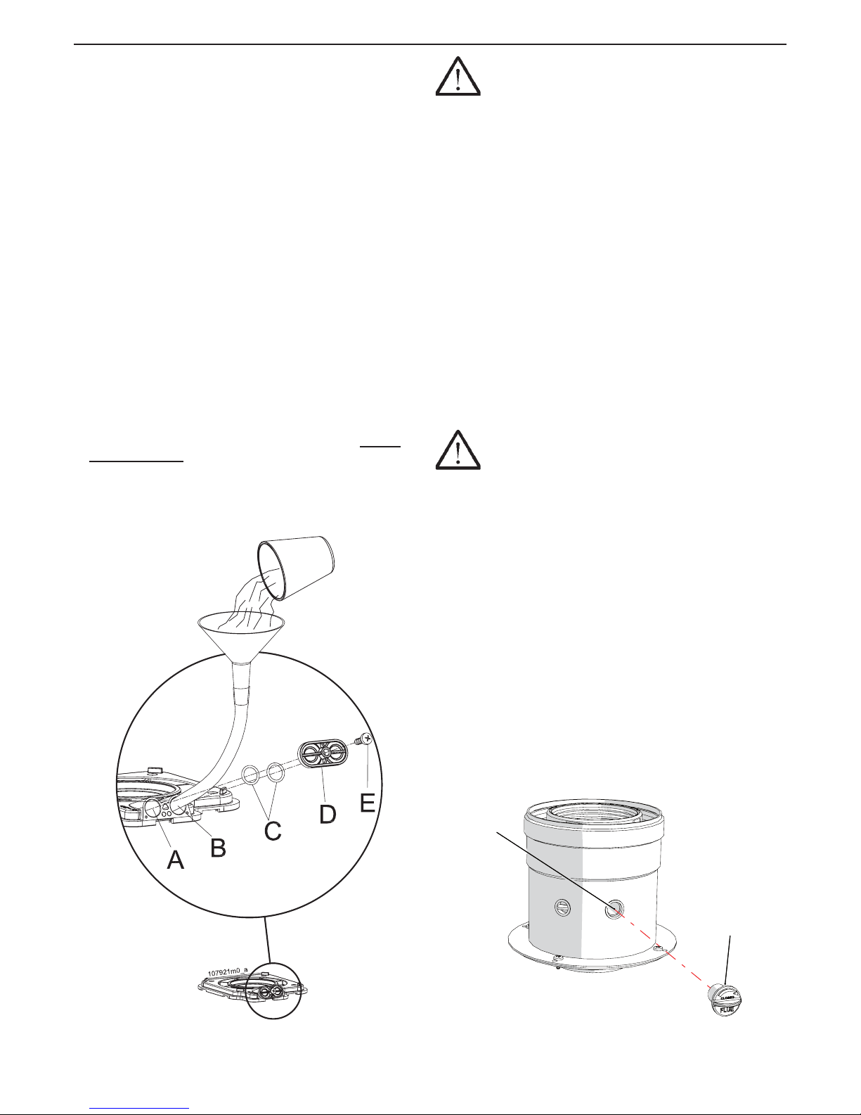
38
AGUADENS
COSMOGAS
6.1 - Operating
Before starting the appliance up, it is necessary to carry out
the following.
6.1.1 - User instructions
Instruct the user regarding correct use of the appliance and
the plant in general. In particular:
Give the installation and user manual and all
documentation contained in the packaging to the user.
Instruct the user concerning the special measures for the
exhaust of burned gases, informing them that they must
not be modied.
Inform the user regarding the correct adjustment of the
temperatures settings.
6.1.2 - Filling the condensate drain siphon
The siphon found inside the appliance (see gures 3-2 and 3-4
detail “40”), must be lled with water to create the water head
able to prevent the fumes escaping from pipe “F” in gure 5-9.
Proceed as follows to do this:
(refer to gure 6-1 for models 16 and 22 or gure 6-2 for
model 37)
1.- loosen the screw “E”;
2.- remove the lid “D” and the gaskets “C”;
3.- introduce a rubber hose into the opening “B” (do not
confuse with “A”) and the other end of the hose into the
funnel;
4.- use the funnel to slowly pour about 200 cm³ (a glass) of
water;
5.- re-mount everything in reverse order.
6 - OPERATING
Figure 6-1 - Filling the condensate drain siphon on
models 16 and 22
ATTENTION !!! If the appliance remains off for
more than 3 months, the siphon must be lled again as
explained above.
6.2 - General recommendations
regarding the supply of gas
For commissioning of the appliance, have a professionally
qualied technician perform the following checks:
That the appliance is powered by the type of fuel for
which it is set-up.
That the gas supply pressure (with appliance operating
and at a standstill) is within the maximum and minimum
values indicated in the table in section 9 at the end of the
manual.
That the supply plant has all safety and control parts
envisioned by the current national and local Standards.
That the exhaust ue terminal discharge terminal and
the combustion agent air intake terminal are free from
any obstruction.
That the exhaust ue terminal and combustion agent air
intake terminal are positioned outside the building.
That the condensate drain connection is connected.
ATTENTION !!! If you smell gas:
A - Do not switch on any electric device, telephone
included or any object that can cause sparks;
B - Immediately open doors and windows causing
a current of air that quickly cleans the gas from
the room;
C - From another room, or from a neighbour’s,
immediately call a professionally qualied
technician or the gas supply company. Call the
Fire Service if the former are not available.
BDB
D
020008.01.023
Figure 6-2 - Filling the condensate drain siphon on
model 37
Page 39
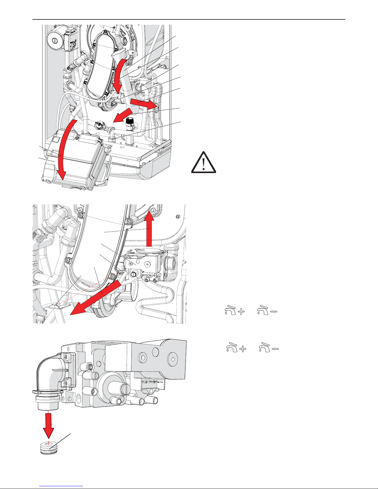
39
AGUADENS
COSMOGAS
6.3 - Type of gas for which the
appliance is regulated.
There is a label on the front of the appliance certifying the
gas supply type and pressure for which it is adjusted.
The appliance may have the following 2 types of wording:
2H-G20-20mbar NATURAL GAS
means that the appliance is adjusted to operate with H type
gas of the second family (natural gas) at a supply pressure
of 20 mbar.
3P-G31-37mbar LP GAS
means that the appliance is adjusted to operate with type P
gas (Propane, also called LP Gas) of the third family, at a
supply pressure of 37 mbar.
6.4 - Conversion of the appliance
from one type of gas to another
ATTENTION !!! Read these instructions carefully
before changing the gas:
- The gas appliance must be installed, calibrated or
modied by specialised staff in compliance with legal
terms;
- Check and be certain that the type of gas which
is powering the appliance is compatible with the
adjustment kit in your possession;
- Do not power the appliance with gases different from
those envisioned.
Follow the instructions given below to change the gas:
1 - disconnect the electric power supply upstream from the
appliance;
2 - open the appliance casing as reported in section 8.2;
3 - access the control and command board as reported in
section 8.2;
4 - move the microswitch “B” from left to right to the “ON”
position (see gure 6-6);
5 - apply electric power to the appliance;
6 - the parameter 3001 will appear on the appliance’s
visual display, followed by its value;
7 - using the
and keys, access the
parameter 3002;
8. - press the RESET key to make the 3002 parameter
ash;
9. - using the
and keys, set the value of
the parameter 3002 to the new corresponding value
according to the table in gure 6-8.
10. - press the RESET key to conrm the modication.
11.- remove voltage from the appliance, re-position the
microswitch “B” from right to left in “OFF” position (see gure
6-6).
12. - close the gas supply;
13. - remove the air manifold making sure to turn it
externally and then slide it out of the fan inlet (see gure
6-3, detail “C”);
15. - remove the gas inlet pipe via the two ttings (see
gure 6-3, details “H” and “L”);
16. - remove the clamping spring “M” from the seat “N”
releasing the valve “P”(See gure 6-4);
G
L
E
A
D
B
H
F
C
020003.01.040
N
Q
O
P
M
020003.01.41
R
020002.01.042
Figure 6-5 - Replacing the gas nozzle
Figure 6-4 - Removing the gas valve
Figure 6-3 - Removing the air manifold
6 - OPERATING
Page 40
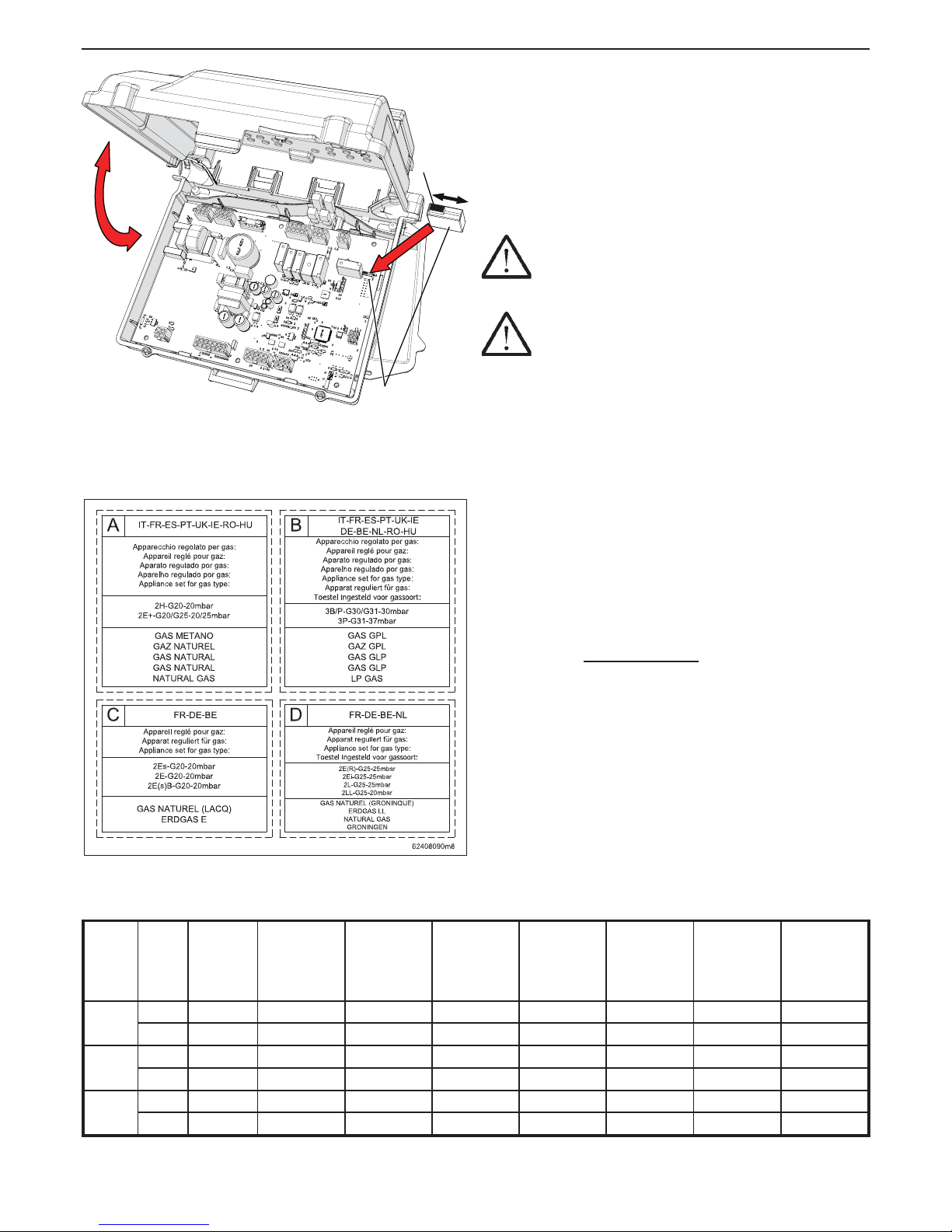
40
AGUADENS
COSMOGAS
17. - slide the gas valve “P” out upwards;
18. - replace the gas nozzle “R” (see gure 6-5) with an
appropriate one according to that stated in gure 6-8
under “Diameter of the gas nozzle”;
19. - remount the gas valve (see gure 6-4, detail “P”),
making sure to reposition the spring “M”.
20. - remount the gas supply pipe via the two ttings (see
gure 6-3, details “H” and “L”);
21. - remount the air manifold (see gure 6-3, detail “C”);
22. - open the gas isolation valve;
23. - check for gas leaks an all joints.
ATTENTION !!! Perform the gas leak test according
to that established by the current Standard and only using
soapy water. The use of naked ames is prohibited.
ATTENTION !!! If you smell gas:
A - Do not switch on any electric device, telephone
included or any object that can cause sparks;
B - Immediately open doors and windows causing
a current of air that quickly cleans the gas from
the room;
C - From another room, or from a neighbour’s,
immediately call a professionally qualied
technician or the gas supply company. Call the
Fire Service if the former are not available.
24.- check the supply gas pressure, following the procedure
in section 6.6;
25.- open the CO2 adjustment screw completely (see gure
6-12 detail “A”);
26.- control and adjust the CO2, following the procedure in
section 6.7;
27.- instead of the label that identified the old state of
adjustment, apply the sticker onto the front casing of
the appliance (see gure 6-7), certifying the appliance’s
new state of adjustment, as follows: apply label “B” if the
appliance has been converted from NATURAL GAS to LP
GAS; apply label “A” if the appliance has been converted
from LP GAS to NATURAL GAS.
B – Microswitch
Figure 6-6 - Positioning the microswitch
A
B
020002.01.043
ON
OFF
6 - OPERATING
Model
Type
of gas
Setting
parameter
3002
Gas supply
minimum
pressure
(mbar)
Gas supply
maximum
pressure
(mbar)
Gas nozzle
diameter
(mm)
CO2
Maximum
power
(%)
CO2
Minimum
power
(%)
O2
Maximum
power
(%)
O2
Minimum
power
(%)
16
G20 50 15 45 4,9 9,0 ±
0,3 8,5 ± 0,2 4,8 ± 0,2 5,5 ± 0,2
G31 51 15 45 3,7 10,5 ± 0,3 10,0 ± 0,2 4,8 ± 0,2 5,6 ± 0,2
22
G20 52 15 45 6,5 9,0 ±
0,3 8,5 ± 0,2 4,8 ± 0,2 5,5 ± 0,2
G31 53 15 45 4,7 10,5 ± 0,3 10,0 ± 0,2 4,8 ± 0,2 5,6 ± 0,2
37
G20 54 15 45 10,0 8,7 ±
0,3 8,3 ± 0,2 4,7 ± 0,2 5,4 ± 0,2
G31 55 15 45 6,5 10,1 ± 0,3 10,8 ± 0,2 4,7 ± 0,2 5,8 ± 0,2
Figure 6-7 - Labels certifying the new status of adjustment of the appliance
Figure 6-8 - Correspondence table for the parameter 3002 and the operating values
Page 41
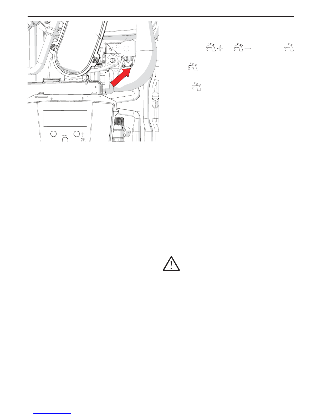
41
AGUADENS
COSMOGAS
6 - OPERATING
6.5 - Ignition
1.- open the gas isolation valve;
2.- power the appliance electrically;
3. - adjust the temperature desired for the domestic hot water
service using the
and keys. The icon
, present on the display will inform regarding the operating
state of the domestic hot water service:
a) xed
icon: domestic hot water inactive (no-one
is withdrawing domestic hot water, or in the case of a
storage tank, the delivery temperature as been reached)
b) ashing
icon: domestic hot water is being withdrawn.
4.- open the domestic hot water tap to the maximum to
evacuate the air inside the water heater. If the water ow
appears to be limited, open two or three taps to evacuate
completely the air. On models 37 you can help by opening
the manual air purge valve (see detail “47“ of gure 3-4 )
6.6 - Check the gas supply pressure
The gas supply pressure must correspond to that stated in
the table in section 9 at the end of the manual.
For its verication, proceed as follows:
1.- close the gas supply manual valve;
2.- access the components inside the appliance, following
the procedure in section 8.2;
3.- loosen the pressure port “A” (see gure 6-9);
4.- connect to a pressure gauge with resolution of at least
0,1 mbar (1 mmH2O);
5.- open the gas manual valve;
6.- check that the pressure does not exceed the value given
in the table in section 9 under “gas supply maximum
pressure”;
7.- open the domestic hot water tap to maximum;
8.- wait for the temperature of the appliance to stabilise;
9.- check that the pressure does not drop to a lower value
than the “gas supply minimum pressure” given in section
9. If the supply pressure does not respect the values
described, operate upstream from the appliance in order
to take it back within the minimum and maximum range;
10.- close the domestic hot water tap;
11.- close the pressure point “A” in gure 6-9;
12.- check for any gas leaks on port “A” in gure 6-9.
CAUTION !!! Perform the leak test using a soap
and water only. The use of naked ames is prohibited.
Figura 6-9 - Valvola del gas
A - Presa di pressione ingresso gas.
A
020003.01.023
Page 42
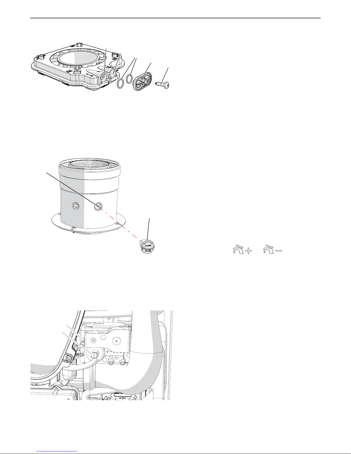
42
AGUADENS
COSMOGAS
6 - OPERATING
6.7 - Measurement and
adjustment of CO2 levels
The appliance in normal operating condition and for altitudes within
1000 m, must have a CO2 (carbon dioxide) level in the exhaust ue
gases within the parameters as detailed in section 9. A value which
is different to those detailed can cause malfunctions and is strictly
prohibited. Combustion analysis must be performed to check and
eventually adjust this value. Proceed as follows:
1.- insert a combustion analyser on the appropriate point on
the ue tting “B” in gure 6-10 or 6-11;
2.- open the domestic hot water tap fully;
3.- wait for the CO2 measurement to stabilise;
4.- compare the value measured with that given in the
table in gure 6-8, “CO2 maximum power”. If the value
measured is different from the value read, it must be
taken back within the value given in the table in gure
6-8. proceeding as follows:
a) turn screw “A” (gure 6-12) clockwise to decrease the
level of CO2;
b) turn screw “A” (gure 6-12) counter-clockwise to increase
the level of CO2;
5.- once the check has been completed, seal the screw “A” in
gure 6-12 with red paint or similar system;
6.- follow section 7.8 to enter parameter 2010 and set it to
Lou;
7.- open a DHW faucet to draw some water;
8.- now appliance will re at minimum capacity;
9.- wait for the CO2 measurement to stabilise;
10.- compare the value measured with that given in the
table in gure 6-8, “CO2 minimum power”;
11.- if the value is not into the range, use screw “B” as per
gure to adjust the CO2 value. Rotate the screw counter-
clockwise to reduce the CO2 value or clockwise to
increase the CO2 value;
12.- once the check has been completed, seal the screw “B”
in gure 6-12 with red paint or similar system;
13.- press the RESET key again to enter the parameter
2010 and use the and keys, to modify
the value to OFF;
14.- press the RESET key to conrm the modication.
15.- hold the RESET key down for 5 seconds to exit the
“installer” menu.
16.- close the previously-opened domestic hot water tap.
Figure 6-10 - Combustion analysis port on models
16 and 22
B
A
C
D
E
020002.01.015
Figure 6-12 - Gas valve
A - High re CO2 adjustment screw
B - Low re CO2 adjustment screw
ABA
B
020002.01.045
Figure 6-11 - Combustion analysis port on model
37
BDB
D
020008.01.023
Page 43
43
AGUADENS
COSMOGAS
6 - OPERATING
6.8 - Self-learning and
calibration of the minimum and
maximum capacity output
This water heater have a self-learning procedure to reach
the best water temperature tuning. In order to do this, the
water heater automatically calibrate the maximum and
minimum capacity based on the typical tappings.
Because at the rst installation it is not known what’s the
typical tappings, for an immediate satisfactory temperature
tuning it is suggested to help the water heater in its selflearning. Operate as follows:
1.- open a hot water faucet to the maximum ow;
2.- using button
, increase the value to the
maximum water temperature;
CAUTION!!! A domestic hot water temperature
exceeding 51°C can cause permanent damages to
persons, animals and objects. Children, the elderly
and disabled must be protected against the potential
risks of scalding, by introducing devices that limit the
temperature of use of domestic hot water to utilities.
3.- water heater should re for at least ve minutes, to its
maximum capacity or to the maximum capacity of the
system where it is installed
4.- now the maximum capacity is calibrated;
5 - enter installer menu (see procedure on section 7.8) and
set parameter 2010 to LOu
6.- now burner will re at minimum capacity. Wait at least
ve minutes;
7.- now the minimum capacity is calibrated;
8.- Turn OFF and ON the water heater (see section 7.10);
9.- close your hot water faucet;
10.- now water heater learned the rst minimum and
maximum limit of this installation and it will correctly tune
the hot water temperature.
6.9 - Adjust the domestic
hot water ow rate
If the appliance is installed in a geographical area where
the temperature of the cold water is very low, the ow rate
of domestic hot water that passes inside the appliance may
have to be reduced. It is therefore good practice to perform
this adjustment:
1.- switch the appliance on;
2.- using the
and keys, adjust the
temperature of the domestic hot water to 48 - 50°C;
3.- open the domestic hot water tap fully. In the case of a
single lever mixer, the position must be completely on
“HOT”;
4.- wait 3 minutes for the temperature to stabilise;
5 - if the water temperature is too cold, the ow rate
must be reduced via the selector “3” in gure 5-10 (or
something similar), until the desired temperature is
reached.
6.10 - Check the capacity input
The heater has a factory-set air/gas ratio. The pressure of
the gas at the burner is indirectly controlled by the blower.
The only way to check the heater capacity input is operating
directly on the gas meter. To do so proceed as follow:
1. turn the power switch (item “A” in Figure 7-1) to on;
2. gain access to the installer menù (see section 7.8) and
set parameter 2010 to HIGH. Now heater will run at high
re for 20 minutes;
3. open a DHW faucet to the maximum ow;
4. measure the capacity input to the gas meter. This should
match with the value given in technical data section 9
header “Maximum heat input” with a tollerance of +/-
10%;
5. if the capacity input is too low, check:
a) that there are no obstructions in the combustion air
and/or vent system;
b) check that the ue and air intake lenght is below the
maximum specied in the technical data, section 9;
c) check that heat exchanger and burner are clean (see
section 8.4).
Page 44
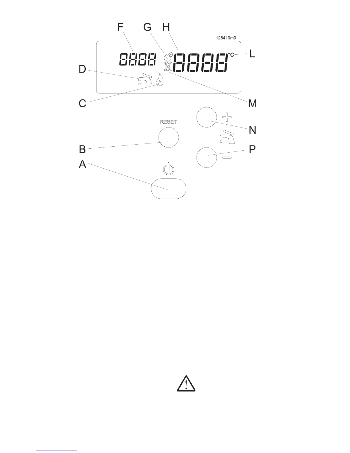
44
AGUADENS
COSMOGAS
7 - USE
Figure 7-1 - Control board
Key for gure 7-1
A - On/off switch
B - Reset Key
C - Burner status (the burner is on when this icon is
present)
D - State of the domestic water service:
Icon off = domestic water off
Icon on = domestic water active but not operating
Icon ashing
= domestic water active and operating
F - Heating plant pressure or indicator of the various
parameters inside the various menus
G - Icon for entry into the “Installer” menu
H - Domestic hot water temperature or indicator of the
values assumed by the various parameters
L - Unit of measurement of the temperature displayed
M - Appliance blocked (see sections 7.9.1 and 7.9.2 for the
diagnostics)
N - Key for switching on and increasing the temperature of
the domestic hot water or for scrolling and changing the
value of the parameters
P - Key for reducing the temperature of the domestic
hot water (below minimum, the domestic hot water is
switched OFF) or for scrolling and changing the value of
the parameters
7.1 - Display
During operation the display shows the appliance operating
state as well as other information as indicated in section 7.9
(Diagnostics). Other parameters can be consulted through
the “User menu” (see section 7.7), which are useful for
understanding operation of the appliance and to control the
latest errors or lockout occurring.
After 5 minutes of normal operation, the display switches off
completely to save energy. Just press any key to switch it
back on.
In the case of any anomaly, the display switches back on
automatically. This function can be modied by following
section 7.6 (Energy saving).
7.2 - Ignition procedure
1.- open the gas manual valve;
2.- power the appliance electrically;
3.- adjust the temperature of the domestic hot water as per
section 7.4.
4.- open a DHW faucet.
The command and control equipment will switch the burner on.
If ignition does not take place within 20 seconds, (the appliance
automatically re-attempts ignition 3 times), the appliance
blocks and the visual display will show Loc 1.
Press the RESET key to restore the normal operating
conditions.
The appliance will automatically attempt a new ignition.
CAUTION !!! If shutdown due to blocking is
repeated frequently, contact a qualied technician to reset
the normal operating conditions.
Page 45

45
AGUADENS
COSMOGAS
7 - USE
7.3 - “User menu”
Entry into the “User menu” is highlighted by the visual display
“F”, in gure 7-1, which indicates parameters that can assume
values from 1001 to 1999. To enter the “User menu”:
1.- hold the RESET key down for 2 seconds until the visual
display “F” shows 1001;
2.- press the
and keys to scroll the parameters
situated inside the user menu;
3.- hold down the RESET key for more than 2 seconds to
exit the “User menu”;
If no key is pressed for more than 60 seconds, the menu is
exited automatically.
The parameters in section 7.7 can be queried in this menu.
7.4 - Adjustment of the domestic
hot water temperature
The temperature of the domestic hot water is adjusted by
operating on the
and keys. On pressing one
of the two keys, the visual display “H” in gure 7-1 will start to
ash and show the temperature that is being set. The range of
adjustment for the temperature of the domestic hot water goes
from 40°C to 60°C. For higher output temperatures, contact
your technician to change the maximum output temperature
factory setting, see section 11.
7.5 - Timings of the various functions
To preserve the life of the appliance, improve the generated
comfort and increase energy savings, have been inserted
timings during operation. These timings are:
- Post circolation pump: each time ending on the domestic
service, the pump continues to operate for 40 seconds;
- Anti-block pumps: every 24 hours is a forcing of the
recirculation pump and of the additional storage tank
charging pump (if present);
- Anti-legionella; if the appliance is connected to a storage
tank for the D.H.W. production, every seven days, this latter
is forced, to temperature of 60°C to perform disinfection
against the bacterium of the legionella. This function turns
ON even after two hours that the appliance has been
electrically powered.
7.6 - Display Energy Saving mode
To reduce the consumption of display energy, it will switch
off automatically after 5 minutes from the last operation
performed. This function can be deactivated or the time
modied via parameter 2100 present in the “Installer menu”
(see section 7.8). If the parameter is set at OFF, the display
will remain on constantly.
Page 46
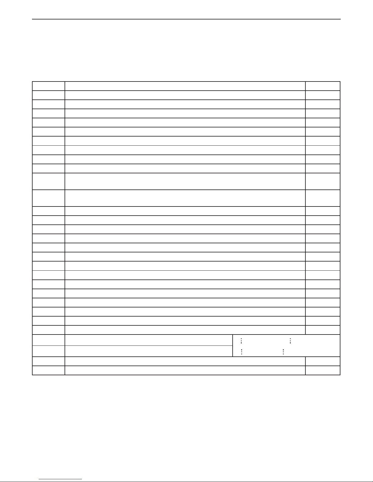
46
AGUADENS
COSMOGAS
7 - USE
Parameter Parameter Description M.U.
1001 Heat exchanger outlet temperature 1 °C
1002 Hot water outlet temperature or storage tank temperature (if any) °C
1003 No function /
1004 External temperature (visible when an external temperature sensor is installed) (N/A) (N/A)
1005 Heat exchanger outlet temperature 2 (safety sensor) °C
1006 Exhaust ue temperature °C
1007 Cold water inlet temperature °C
1008 Ionisation current uA
1009 Status of the pump inside the appliance ON/OFF
1010 Status of the central heating side diverter valve
(OFF = in central heating mode; ON = in domestic hot water mode) (N/A)
(N/A)
1011 Status of the central heating side diverter valve
(ON = in D.H.W. mode; OFF = in central heating mode) (N/A)
(N/A)
1012 Central heating supply temperature calculated via the external sensor (N/A) (N/A)
1013 Status of the timer contact (N/A) open or closed
1014 Exhaust ue temperature 2 (safety sensor) (N/A) (N/A)
1040 Current rotation speed of the fan rpm
1041 Fan rotation speed on ignition rpm
1042 Fan rotation speed in minimum power mode rpm
1043 Fan rotation speed in maximum power mode rpm
1051 Latest block condition recorded (Loc) (see section 7.9.1) (255 means no block) /
1052 Latest error condition recorded (Err) (see section 7.9.2) (255 means no error) /
1053 Number of times the burner has lost the ame n°
1055 Number of failed burner ignitions n°
1056 Number of hours worked in central heating mode (N/A) (N/A)
1057 Number of hours worked in domestic hot water mode h x 10
1058 Number of burner working days days
1059 Interval of time between the last two blocking errors (Err)
1 value in minutes; 2 value in hours;
3 value in days; 4 value in weeks;
1060 Interval of time between the last two blocks (Loc)
1061 Current rotation speed of the domestic hot water turbine (N/A) (N/A)
1062 Current domestic hot water ow rate (Meter have a tolerance of +/- 15%) l/min
N/A = Not applicable
7.7 - “User menu” Parameters
To access the “User menu” follow that reported in section 7.3.
The following parameters can be queried in this menu:
Page 47
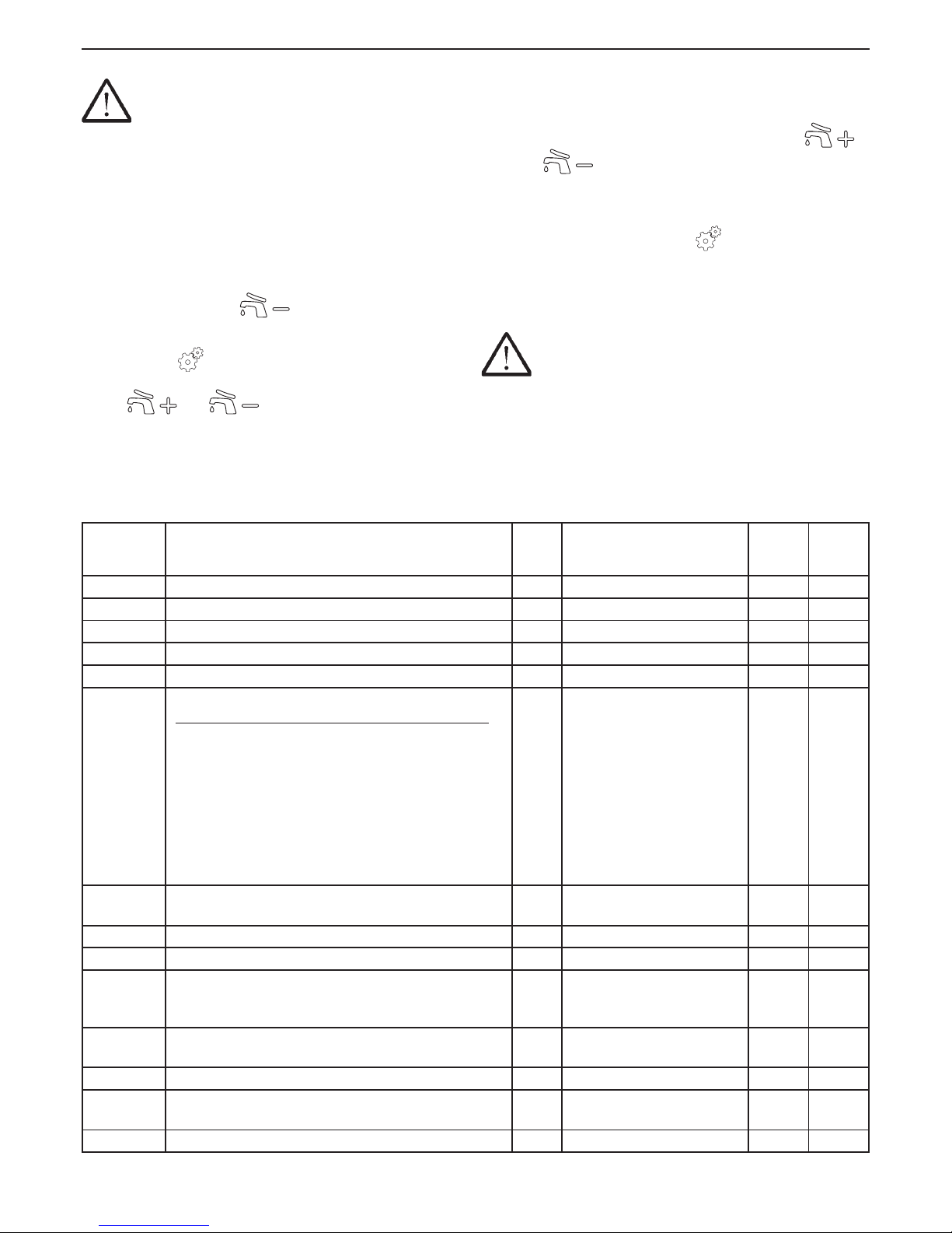
47
AGUADENS
COSMOGAS
7.8 - “Installer menu” & parameters
ATTENTION !!! The modication of these
parameters could cause the appliance, and
therefore the plant, to malfunction. For this reason
only a technician that has the awareness and indepth knowledge of the appliances can modify
them.
The appliance command and control board makes this
parameter menu available to the technician for the analysis
of operation and adaptation of the appliance to the plant.
Proceed as follows to enter the “Installer menu”:
1.- hold the RESET and
keys down simultaneously
for 5 seconds until the 2001 parameter is displayed.
The symbol
appears on the display to indicate the
entry into the “Installer menu”.
2.- the
and keys can be used inside the
menu to scroll the parameters;
3.- once the parameter of interest has been displayed, it
can be modied as follows:
a.- press the RESET key to access the parameter (the
visual display “H” in gure 7-1 will start to ash);
b.- modify the value of the parameter using the
and
keys;
c.- press the RESET key to conrm the data modied
and go back to the list of parameters;
4.- To exit the “Installer menu”, hold down the RESET key
for 5 seconds until the symbol
disappears from the
display.
If no key is pressed for more than 5 minutes, the menu is
exited automatically. Any data variation that is not conrmed
with the RESET key will be lost.
ATTENTION !!! Any variation to the
parameters must be noted in the “Customised
values” column present in the following table in
order to facilitate the eventual replacement of the
command and control board.
The following parameters can be changed or queried in this
menu:
7 - USE
Parameter Parameter Description M.U. Setting range
Factory
value
Custo-
mised
values
2001 Central heating minimum power level (N/A) (N/A) (N/A) 1 (N/A)
2002 Central heating maximum power level (N/A) (N/A) (N/A) 100 (N/A)
2003 Central heating operating mode (N/A) (N/A) (N/A) 0 (N/A)
2004 Stand-by time after maximum differential (N/A) (N/A) (N/A) 10 (N/A)
2005 Post-circulation in central heating mode (N/A) (N/A) (N/A) 120 (N/A)
2010
Forcing of fan and burner
(Water heater will work only in presence of demand of DHW)
/
OFF = No forcing
FAN = Forcing of fan only to
max speed
LOu = Forcing of burner to
minimum power
Ign = Forcing of burner to ignition power
HIgH = Forcing of burner to
maximum power
rEg = Forcing of burner to maximum power
OFF
2011 Forcing the pump (N/A)
(N/A)
On = Pump on
OFF = Pump off
OFF
(N/A)
2012 Forcing of the domestic central heating side diverter valve (N/A) (N/A) (N/A) OFF (N/A)
2013 Forcing of the domestic hot water side diverter valve (N/A) (N/A) (N/A) OFF (N/A)
2014 Icons test on the display. By pressing the REST key, all of the
icons on the display light up. By pressing the RESET key again
to display goes back to normal operation
/ / /
2020 Climatic adjustment: external temperature for central heating
switch-off (N/A)
(N/A) (N/A) 22 (N/A)
2021 Climatic adjustment: design external temperature (winter) (N/A) (N/A) (N/A) -5 (N/A)
2022 Climatic adjustment: supply temperature corresponding to the
design external temperature (winter) (N/A)
(N/A) (N/A) 80 (N/A)
2023 Climatic adjustment: external spring-like temperature (N/A) (N/A) (N/A) 20 (N/A)
Page 48
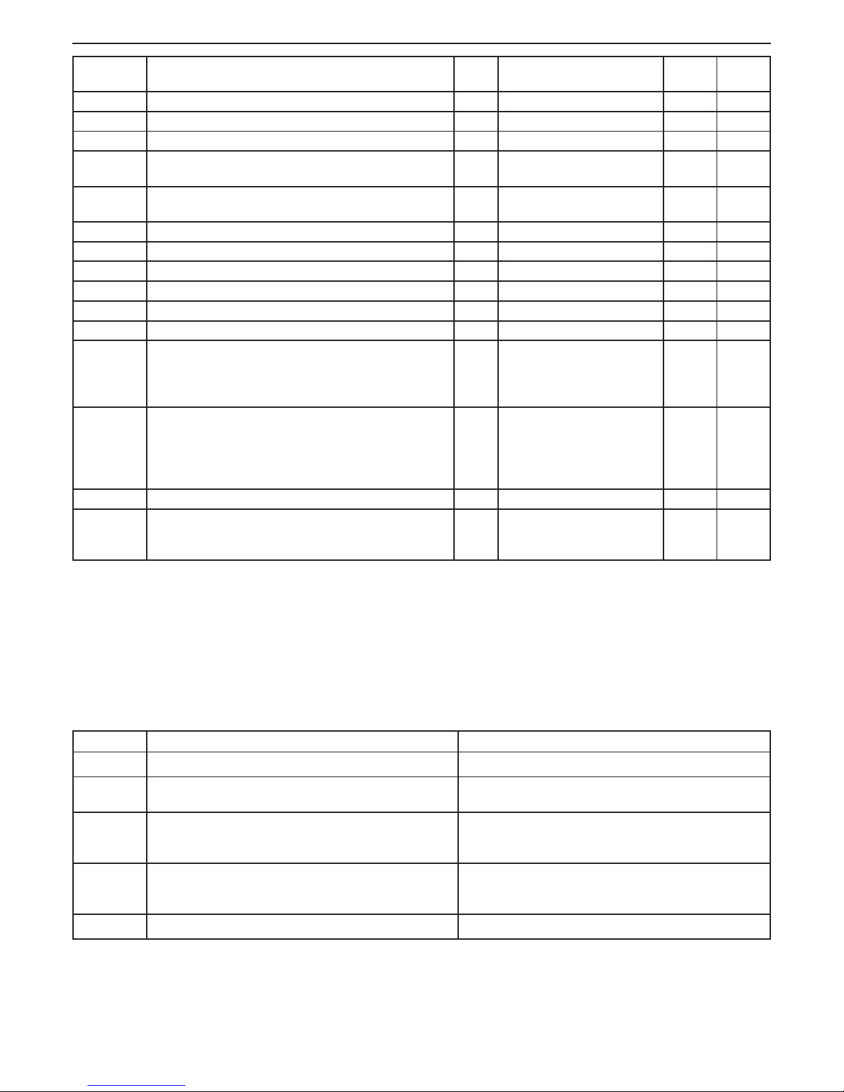
48
AGUADENS
COSMOGAS
7 - USE
2024 Climatic adjustment: supply temperature corresponding to the
external spring-like temperature (N/A)
(N/A) (N/A) 40 (N/A)
2027 Temperature reduction by room thermostat opening (N/A) (N/A) (N/A) 10 (N/A)
2040 Climatic adjustment: central heating boost temperature (N/A) (N/A) (N/A) 0 (N/A)
2041 Climatic adjustment: central heating boost time (N/A) (N/A) (N/A) 20 (N/A)
2042 Protection against frequent switch-on in central heating mode:
time (N/A)
(N/A) (N/A) 180 (N/A)
2043 Protection against frequent switch-on in central heating mode:
temperature differential (N/A)
(N/A) (N/A) 16 (N/A)
2060 Domestic hot water minimum power level % From 1 to 50 1
2061 Domestic hot water maximum power level % From 1 to 100 100
2062 Post-circulation in domestic hot water mode sec From 10 to 900 40
2063 Maximum time for loading storage tank (N/A) (N/A) (N/A) 60 (N/A)
2064 Number of ow meter revs. for every litre of water (N/A) (N/A) (N/A) 3,2 (N/A)
2066 Delay in the detection of the instantaneous domestic hot water sec From 1 to 10 1
2067 Storage tank loading procedure (N/A)
/
0 = (N/A);
1 = (N/A);
2 = ON, the domestic hot water
always has priority over heating;
2
2080 Periodic maintenance meter
(after RESET, the meter automatically goes back to ON)
/
ON = Periodic maintenance
meter active;
OFF = Periodic maintenance
meter off;
RESE = Meter reset
OFF
2081 Periodic maintenance meter: maintenance request time days From 0 to 1000 1000
2100 Energy saving display
min
OFF = display always on
From 1 to 30 = delay to switch-
off in minutes.
5
7.9 - Diagnostics
During normal operation of the appliance, the visual display
in gure 7-1 continuously shows the state of work of the
appliance, via the following indications:
Parameter Parameter Description Display on visual display “H” in gure 7-1
AFro
Anti-freeze function active Appliance temperature (°C)
Loc
Appliance blocked. To reset, press RESET. If the block occurs
frequently, contact a professionally qualied technician
Lockout code (see section 7.9.1 for decode)
Err
Appliance in error mode. Functioning can only be restored by
solving the cause of the anomaly. Contact a professionally
qualied technician
Error code (see section 7.9.2 for decode)
ALEg
Anti-legionella function running (see section 7.5).
It will end on reaching the water temperature of 60°C inside the
storage tank.
Storage tank temperature (°C)
SEr
Maintenance request for the appliance Appliance temperature (°C)
Page 49
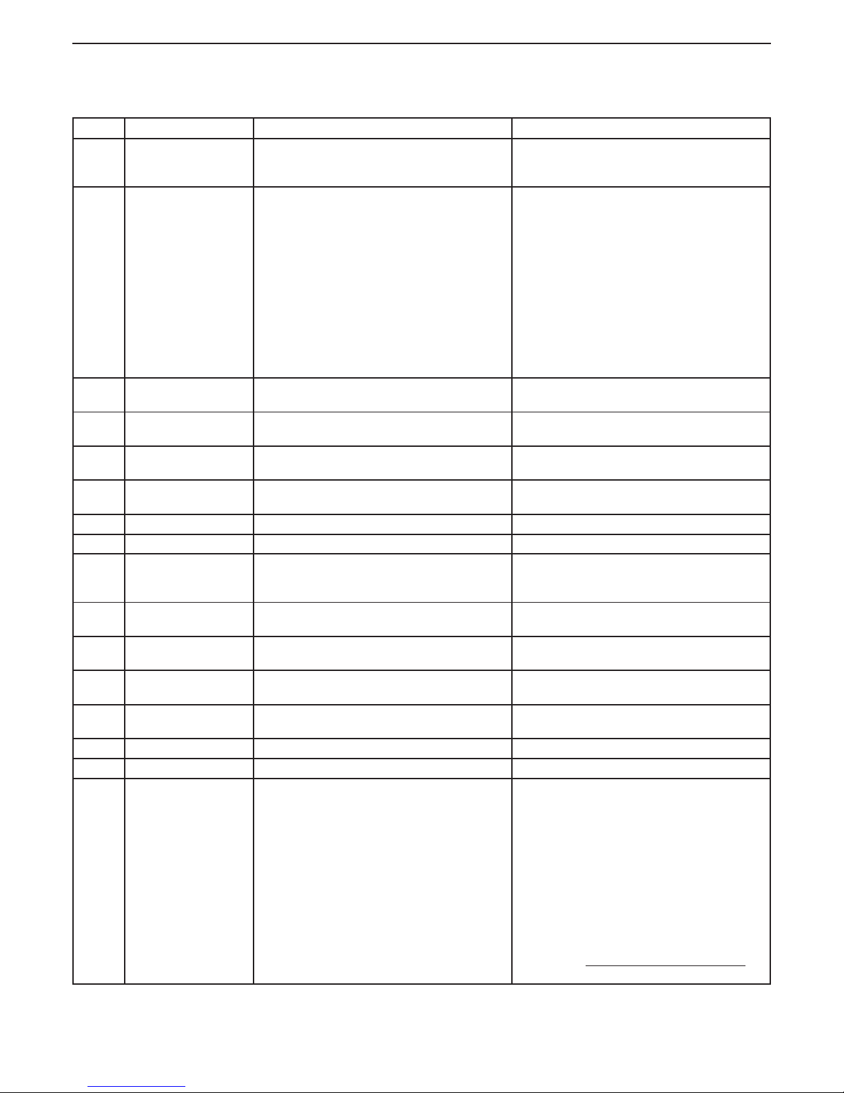
49
AGUADENS
COSMOGAS
7.9.1 - Diagnostics “Loc” block fault codes
and potential solution
7 - USE
Block Block Description Checks Solutions
Loc 0 Internal memory error
E2prom at command
board
Replace the command and control board.
Loc 1 1 No ame detection after
three successive ignition
attempts.
Control: Supply gas pressure (see section 6.6),
sparks on the ignition electrodes (see section 8.6);
230Vac electric power supply to the gas valve;
electric resistance of the two gas valve coils of 0,88
Kohm and 6,59 Kohm
If the burner switches on and switches off at the end
of the ignition attempt, check: that the ionisation
current is at a value over 4 (follow the procedure in
section 8.13)
the supply pressure is not correct, operate upstream
from the appliance to restore it; If the current at the
gas valve is not 230Vac, the command and control
board must be replaced. If the electric resistance of
the gas valve is not 0,88 Kohm and 6,59 Kohm, the
valve must be replaced.
If the ionisation current is not over 4, the CO2 must
be checked (follow section 6.7) and restore its
correct value, check the ionisation electrode and
replace it if necessary. Check the integrity of the
ionisation current electric circuit cables.
Loc 2 Gas valve command relay
broken
Replace the command and control board.
Loc 3 Int e rnal s afet y rela y
failure at command board
Replace the command and control board.
Loc 4 Appliance in error mode
for more than 20 hours
Control the last error displayed in the board. Operate according to the last error displayed.
Loc 5 Fan out of speed for
more than 60 seconds
Check that it is powered at 300 Vdc. If the fan is powered, it must be replaced, alternatively
replace the command and control board.
Loc 6 Fan error too slow
Loc 7 Fan error too fast
Loc 8 Parameters inside
the E2prom memory,
incorrect
Replace the command and control board.
Loc 9 Software error inside the
command board
Replace the command and control board.
Loc 10 Software error inside the
command board
Replace the command and control board.
Loc 11 Software error inside the
command board
Replace the command and control board.
Loc 12 Software error inside the
command board
Replace the command and control board.
Loc 13 Not applicable (N/A) (N/A)
Loc 14 Not applicable (N/A) (N/A)
Loc 15 Appliance has reached
the maximum temperature of operation
Check that the pump works;
Check that the electrical resistance of the two sensors
1001 and 1005 combine with the chart referred to in
section 8.14;
Check that the high limit ue gas temperature fuse has
not been involved;
Check air is purged from water heater (see section 6.5);
Restore the ow of water or
replace the control board;
If either or both of the sensors are not within correct
values, replace sensor;
If the high limit ue gas temperature fuse has been
involved (the contact is open) before replacing the high
limit verify the temperature of the ue gas referred to
in the technical data from section 9;
CAUTION!!! If the temperature is not within the
correct value DO NOT ATTEMPT ANY REPAIR but
contact the manufacturer.
Page 50
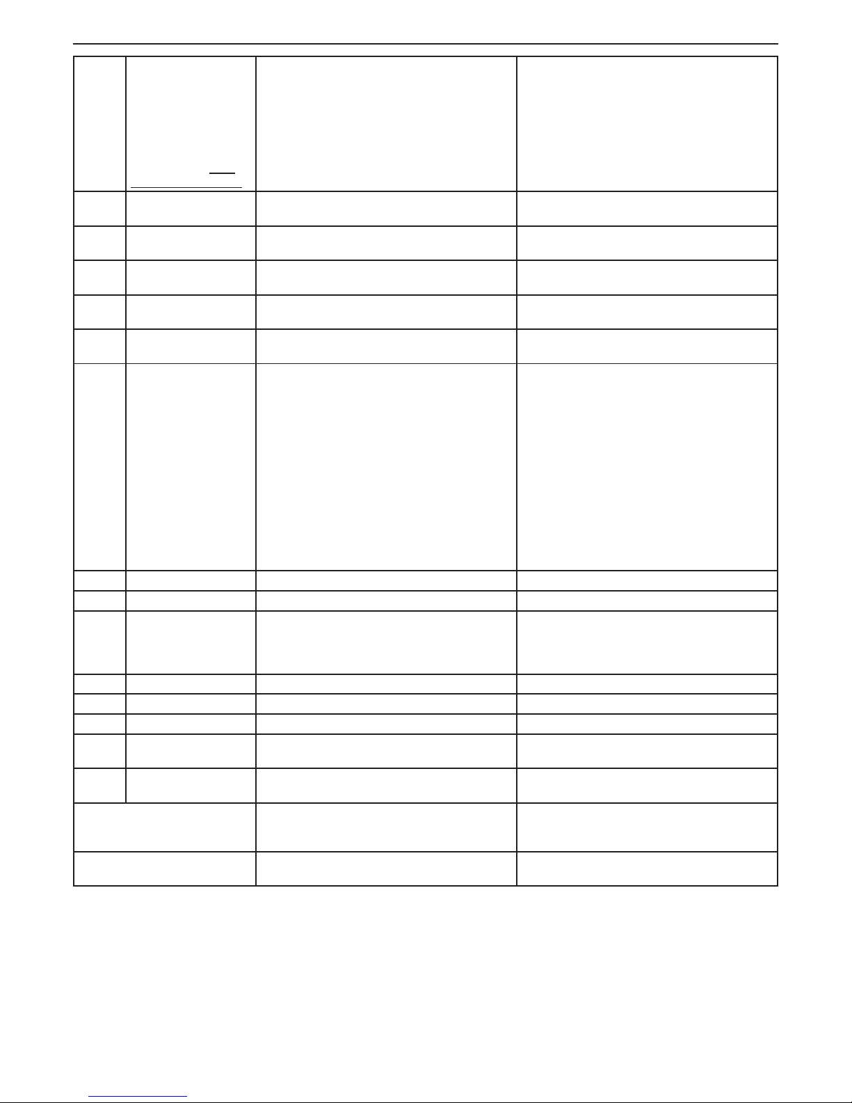
50
AGUADENS
COSMOGAS
7 - USE
Loc 16 Exhaust ue maximum
temperature.
ATTENTION !!! If the
block is repeated more
than once a day, turn
off the appliance and
contact a qualied
service center. NOT
GROPE TO RESTORE.
Check that the pump is operating correctly;
Measure that appliance performance; it must correspond to that declared in the technical features.
Check air is purged from water heater (see section 6.5)
If the pump does not operate, it must be replaced.
If the appliance is under-performing, the primary
heat exchanger might be dirty either on the exhaust
ue side or the domestic water side or both. Follow
instructions in section 8.4 and check again.
Loc 17 Software error inside the
command board
Replace the command and control board.
Loc 18 Software error inside the
command board
Replace the command and control board.
Loc 19 Software error inside the
command board
Replace the command and control board.
Loc 20 Flame still present 10 sec.
after closing gas valve
Replace the gas valve or the command and control
board.
Loc 21 Flame present before
ignition
Replace the gas valve or the command and control
board.
Loc 22 Flame lost three times Control: that the ionisation current is at a value over 4
(follow the procedure in section 8.13)
Control: that the exhaust ue system is not being
affected by high gusts of wind or nearby mechanically
operated fans
If the ionisation current is not over 4, the CO2 must be
checked (follow section 6.7) and restore the correct
value. Check the ionisation electrode and replace it if
necessary. Check the integrity of the ionisation current
electric circuit cables.
If a horizontal exhaust ue terminal is exposed to
unusually high wind conditions or nearby mechanically
operated fans then a suitable deection shield or
protection should be considered or an alternative
location should be considered. The same approch
should be taken for a vertical exhaust ue and in
addiction, check that downdraughts are not being
encountered due to the proximity of higher roof proles.
Loc 23 Not applicable (N/A) (N/A)
Loc 24 Not applicable (N/A) (N/A)
Loc 25 1001 and 1005 sensors
measure the different
temperatures for more
than 60 seconds.
Check that the electrical resistance of the two sensors
match the graphics in section 8.14;
If one of the two or both sensors do not have correct
values, they must be replaced;
Loc 26 Not applicable (N/A) (N/A)
Loc 27 Not applicable (N/A) (N/A)
Loc 28 Not applicable (N/A) (N/A)
Loc 29 Software error inside the
command board
Replace the command and control board.
Loc 30 Software error inside the
command board
Replace the command and control board.
Hot water temperature is not stable Repeat calibration procedure (see section 6.8)
Check if pump is in speed 3
Water ow is present but the water
heater doesn’t work
Check if the water ow (parameter 1062) is higher
than the minimum water ow as stated on section 7.7.
N/A = Not applicable
Page 51
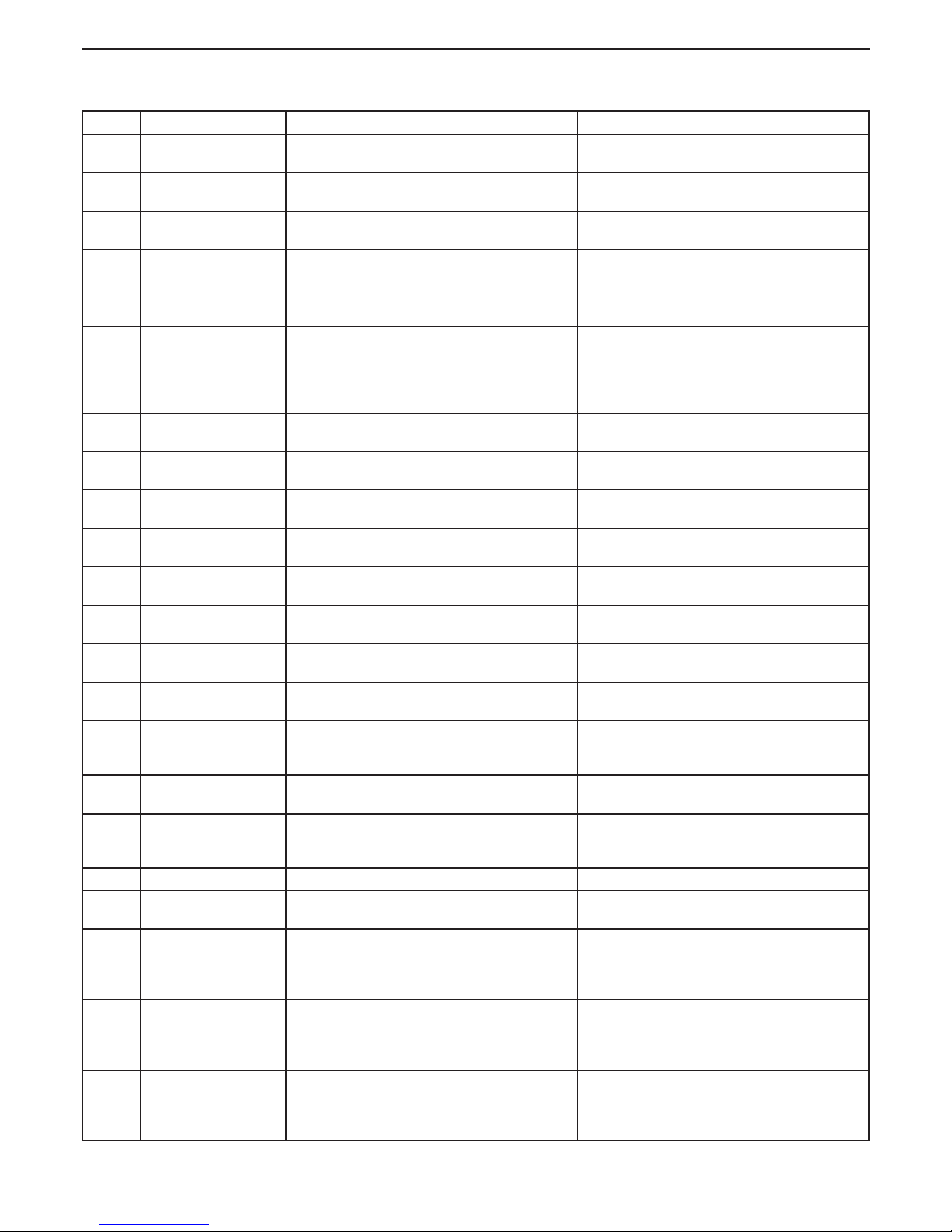
51
AGUADENS
COSMOGAS
7 - USE
7.9.2 - Diagnostics “E” error fault codes
and potential solutions
Error Error Description Checks Solutions
Err 100 Software error inside the
command board
Replace the command and control board.
Err 101 Software error inside the
command board
Replace the command and control board.
Err 102 Software error inside the
command board
Replace the command and control board.
Err 103 Software error inside the
command board
Replace the command and control board.
Err 104 Software error inside the
command board
Replace the command and control board.
Err 105 The supply temperature
exceeds 110°C with the
gas valve closed
Check that the electrical resistance of the two supply
sensors match the graphics in section 8.14.
Check that the gas valve closes the gas correctly
when the burner switches off.
If one of the two sensors does not match, the double
supply sensor must be replaced.
The gas valve must be replaced if it does not close
correctly.
Err 106 Software error inside the
command board
Replace the command and control board.
Err 107 Software error inside the
command board
Replace the command and control board.
Err 108 Software error inside the
command board
Replace the command and control board.
Err 109 Software error inside the
command board
Replace the command and control board.
Err 110 Software error inside the
command board
Replace the command and control board.
Err 111 Software error inside the
command board
Replace the command and control board.
Err 112 Software error inside the
command board
Replace the command and control board.
Err 113 Software error inside the
command board
Replace the command and control board.
Err 114 Flame detected in a
moment when it should
not be present
Replace the gas valve.
Err 115 Central heating water
low pressure (N/A)
(N/A) (N/A)
Err 116 Central heating water
pressure sensor error
(N/A)
(N/A) (N/A)
Err 117 Not applicable (N/A) (N/A)
Err 118 Software error inside the
command board
Replace the command and control board.
Err 119 Cold water inlet sensor
(1007) circuit open
Check that the electric resistance of the sensor
matches the graphics in section 8.14. Check the
electric cables for connection between the sensor
and the command board.
If the electric resistance does not match, replace it.
The electric circuit must be repaired if it is damaged.
Without either of the two previous cases, replace the
command and control board.
Err 120 Heat exchanger outlet
sensor (1001) circuit
open
Check that the electric resistance of the sensor
matches the graphics in section 8.14. Check the
electric cables for connection between the sensor
and the command board.
If the electric resistance does not match, replace it.
The electric circuit must be repaired if it is damaged.
Without either of the two previous cases, replace the
command and control board.
Err 121 Heat exchanger outlet
sensor (1005) circuit
open
Check that the electric resistance of the sensor
matches the graphics in section 8.14. Check the
electric cables for connection between the sensor
and the command board.
If the electric resistance does not match, replace it.
The electric circuit must be repaired if it is damaged.
Without either of the two previous cases, replace the
command and control board.
Page 52
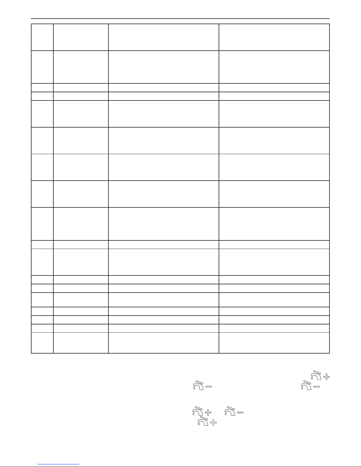
52
AGUADENS
COSMOGAS
7 - USE
Err 122 Domestic hot water
outlet sensor (1002)
circuit open
Check that the electric resistance of the sensor
matches the graphics in section 8.14. Check the
electric cables for connection between the sensor
and the command board.
If the electric resistance does not match, replace it.
The electric circuit must be repaired if it is damaged.
Without either of the two previous cases, replace the
command and control board.
Err 123 Flue gas sensor (1006)
circuit open
Check that the electrical resistance of the sensor
matches the graphics in section 8.14
Check that the wires between the board and the
sensor are connected correctly
If the sensor does not match, the double exhaust
sensor must be replaced.
If the wires are not connected correctly, the connections must be restored.
Err 124 Not applicable (N/A) (N/A)
Err 125 Not applicable (N/A) (N/A)
Err 126 Cold water inlet sensor
(1007) circuit, in short
circuit condition
Check that the electric resistance of the sensor
matches the graphics in section 8.14. Check the
electric cables for connection between the sensor
and the command board.
If the electric resistance does not match, replace it.
The electric circuit must be repaired if it is damaged.
Without either of the two previous cases, replace the
command and control board.
Err 127 Heat exchanger outlet
sensor (1001) circuit, in
short circuit condition
Check that the electric resistance of the sensor
matches the graphics in section 8.14. Check the
electric cables for connection between the sensor
and the command board.
If the electric resistance does not match, replace it.
The electric circuit must be repaired if it is damaged.
Without either of the two previous cases, replace the
command and control board.
Err 128 Heat exchanger outlet
sensor (1005) circuit, in
short circuit condition
Check that the electric resistance of the sensor
matches the graphics in section 8.14. Check the
electric cables for connection between the sensor
and the command board.
If the electric resistance does not match, replace it.
The electric circuit must be repaired if it is damaged.
Without either of the two previous cases, replace the
command and control board.
Err 129 Domestic hot water out-
let sensor (1002) circuit,
in short circuit condition
Check that the electric resistance of the sensor
matches the graphics in section 8.14. Check the
electric cables for connection between the sensor
and the command board.
If the electric resistance does not match, replace it.
The electric circuit must be repaired if it is damaged.
Without either of the two previous cases, replace the
command and control board.
Err 130 Flue gas sensor (1006)
circuit in short circuit
condition
Check that the electrical resistance of the sensor
matches the graphics in section 8.14
Check that the wires between the board and the
sensor are connected correctly
If the sensor does not match, the double exhaust
sensor must be replaced
If the wires are not connected correctly, the connections must be restored
Err 131 Not applicable (N/A) (N/A)
Err 132 External temperature
sensor circuit (1004) in
short circuit condition
(N/A)
(N/A) (N/A)
Err 133 Not applicable (N/A) (N/A)
Err 134 Not applicable (N/A) (N/A)
Err 135 Phase neutral reversed
error
(N/A) (N/A)
Err 200 Not applicable (N/A) (N/A)
Err 201 Not applicable (N/A) (N/A)
Err 202 Not applicable (N/A) (N/A)
Err 203 Too high difference
between supply and
return sensor
(N/A) (N/A)
N/A = Not applicable
7.10 - Switch ON and OFF the appliance
To switch Off the appliance press in the same time the
and
keys and On will appear then press key
and OFF will appear; Press RESET key to conrm the OFF
state. To switch back ON the appliance press in the same time
the
and keys and OFF will appear. Then
press
key and On will appear; press RESET key to
conrm the On state.
Page 53
53
AGUADENS
COSMOGAS
8 - MAINTENANCE
8.1 - Care and maintenance
This section must be brought to the attention of the user by the
installer so that the user can make the necessary arrangements
with a qualified service agency for the periodic care and
maintenance of the heater.
The installer must also inform the user that the lack of proper care
and maintenance of this heater and any fuel burning equipment
may result in an hazardous condition.
Installer should discuss contents of section 7 (User’s section)
with the user.
A trained and qualied service technician should perform the
inspection listed in these instructions (see gure 8-1) each year.
CAUTION !!! Appliance maintenance must only
be performed by a professionally qualied technician.
CAUTION !!! Before every maintenance
operation, disconnect the appliance from the electric
power supply, using the relevant switch in the vicinity.
CAUTION !!! Close the manual gas valve before
any maintenance operation
Service and maintenance schedules
Service Technician
Annual Startup:
- Address reported problems (Follow section 8.1.2);
- Check all piping for gas leaks (Follow section 8.1.3)
- Verify ue and air lines in good condition and sealed tight (Follow
section 8.1.4);
- Check water pressure/system piping (Follow section 8.1.5);
- Check control settings (Follow section 8.1.6);
- Check wiring and connections (Follow section 8.1.7);
- Check ame signal (Follow section 8.6);
- Inspect combustion chamber. Clean and vacuum if ther’is presence of
debris and/or products of the combustion (Follow section 8.4).
- Inspect thermal insulations inside the combustion chamber and replace
them if they are cracked or damaged (Follow section 8.3.1)
- Clean condensate siphon and ll with fresh water (Follow section 8.5).
- Check the capacity input (Follow section 6.10).
Figure 8-1 - Service and Maintenance Schedules
8.1.1 - Service recall
In order to maintain maintenance frequency, the parameter
2080 is present in the installer menu (see section 7.8),
which is used to activate the maintenance call (Service)
along with parameter 2081 which is used to set the
operating days which must pass between one intervention
and the next. The control system identies the operating
days, verifying the burner activity time.
Proceed as follows to activate the call service:
1.- access the Installer menu (see section 7.8)and set
parameter 2080 on 0n;
2.- access parameter 2081 and set the appliance
operating days which must pass between one call and
the next.
The call will be completed with
SEr on the display. To
remove the indication SEr and renew the call period,
operate as follows:
1.- access the “Installer menu”;
2.- access the parameter 2080, set it on rESE and
press the RESET key.
3.- exit the Installer menu by pressing the RESET key for 5
seconds.
The call time is now renewed and SEr appears on the
display.
8.1.2 - Address reported problems
Inspect any problems reported by the owner and correct before
proceeding.
8.1.3 - Check all piping for gas leaks
1. Inspect all gas piping and verify to be leak free.
2. Check for gas leaks: using soap solution, check for gas
leaks from meter to appliance including all pipes and ttings
and heater connection. Use liquid soap solution for all gas
testing.
CAUTION !!!
Do not check for gas leaks with an
open ame. Use the bubble test. Ignoring the bubble
test or check for gas leaks with an open ame can cause
explosion, severe personal injury, death, or substantial
property damage.
8.1.4 - Verify ue and air lines in good
condition and sealed tight;
1. Check for obstruction, condensation, corrosion and physical
damage, water stains, any signs of rust, other corrosions or
separation of the vent and air intake piping.
2. Check outside terminations. Screens and louvers should be
free of any debris and must be cleaned as required.
8.1.5 - Check system water pressure/
system piping/expansion tank;
1. Check water piping and accessories for leaks. Slightest
leaks should be corrected.
2. Check the system to be full of water and pressure to remain
stable at correct setting on gauge.
CAUTION !!!
Eliminate all system or heater leaks.
Continual fresh makeup water will reduce heater life.
Minerals can build up in sections, reducing heat transfer,
overheating heat exchanger, and causing heat exchanger
failure. Leaking water may also cause severe property
damage.
8.1.6 - Check control settings
1. Set heaters setpoint low enough to end call for heat (see
section 7.4. Gas valve should close and burner should stop
ring. Fan will go into a post purge, then shuts off.
2. Control Safety Shutdown test: with the burner ring, close the
manual gas shut off valve (detail “2” Figure 5-10). Gas valve
should close and burner should stop ring. The boiler will
try for ignition three times, then should lock out with a “Loc
1” error shown on the display. Open the manual gas shutoff valve, and verify your gas meter.
Gas ow must be zero
.
Page 54
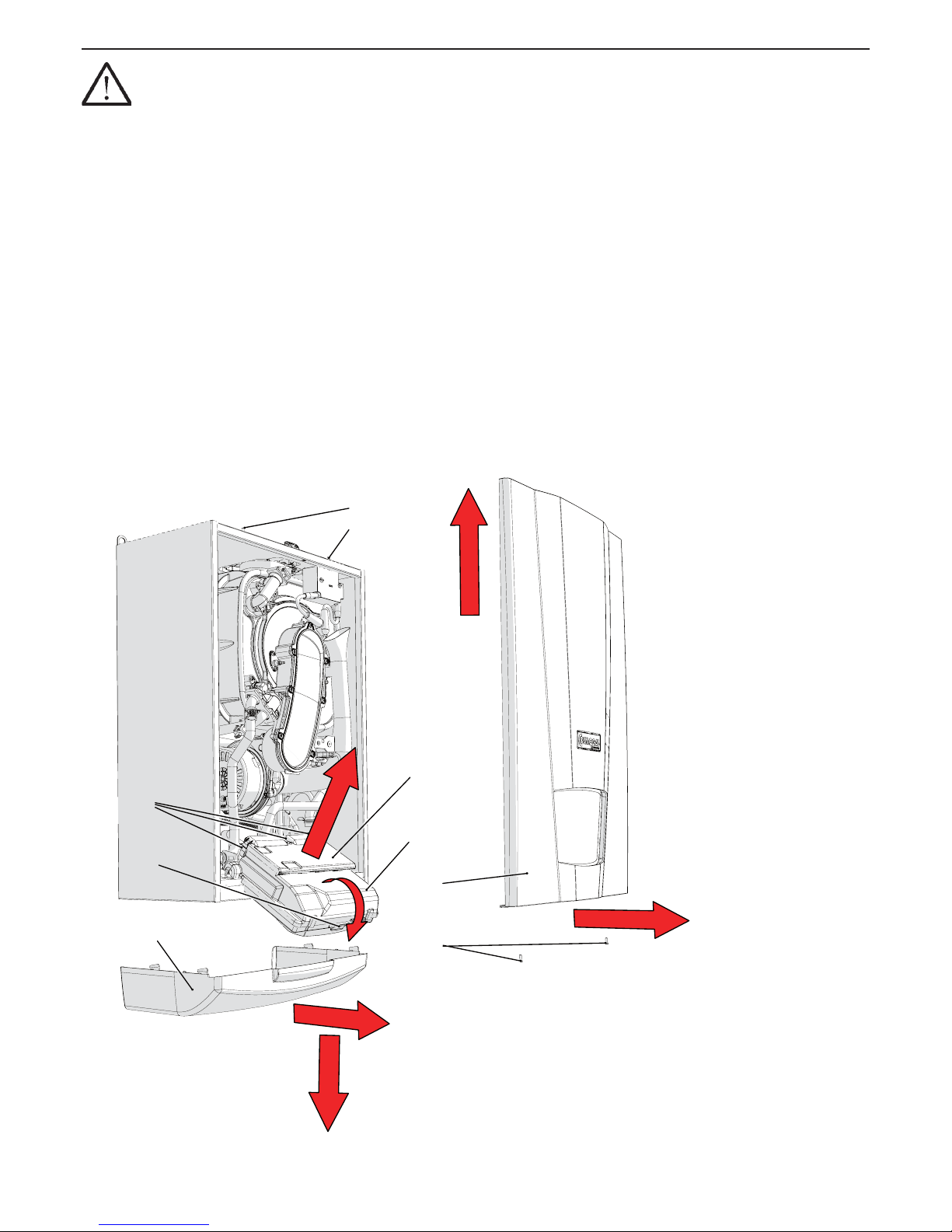
54
AGUADENS
COSMOGAS
Figure 8-2 - removing the casing and opening of command board
C
E
D
G
H
F
A
B
020003.01.018
8 - MAINTENANCE
CAUTION !!!
If gas ow occurs, close the manual gas
shutoff valve and troubleshoot the system to determine why
there is gas ow when the gas valve should be deenergized.
Do not operate the boiler until the problem is resolved or a
re or explosion causing property damage, personal injury
or loss of life may occur!
3. Press the “Reset” key to return to normal operation.
8.1.7 - Check wiring and connections
Inspect all heater wiring, making sure wires are in good
condition and securely attached.
8.2 - Casing removal
Proceed as follows to remove the casing (refer to gure
8-2):
1.- pull the lower cover “A” towards the front for approx.
10mm
2.- push the lower cover “A” downwards;
3.- loosen the screws “H”;
4.- pull the lower part of the front-piece “B” towards the front
and then slide it out upwards until it is released from the
guides “C”;
To access the command and control board:
1.- turn the command board “D” towards the front;
2.- open the commands board “D” by operating on closure
“G”;
To access the electric connections board:
1.- turn the command board “D” towards the front;
2.- slide lid “E” out by operating on the “F” closing aps;
Page 55
55
AGUADENS
COSMOGAS
8 - MAINTENANCE
8.3 - Burner and fan removal
Proceed as follows to remove the burner fan unit (refer to
gure 8-3 when not differently specied):
1.- access the internal components following section 8.2;
2.- remove the air manifold (detail “C” in gure 6-3) rotating
it towards the outside of the appliance and then pulling it
towards the right (see gure 6-3);
3.- unscrew nut “C” from the valve “D”;
4.- disconnect the cables “B” and the detection cable from
the ignition and detection electrodes (details “15” and
“35” of gures 3-1, 3-2, 3-3 and 3-4);
5.- unscrew the four nuts “E”;
6.- extract the group “F” as per gure;
8.3.1 - Thermal insulations
Thermal insulations must be checked every year and replaced
if they are cracked or damaged. See Figures 8-3 where the
thermal insulations (items “G” and “H”) are showed assembled
in the burner and in the heat exchanger.
Once veried the condition of thermal insulation (see
Figure 8-3), if necessary, replace with spare parts kit,
following the instructions supplied with it. With the
thermal insulation must be replaced the burner gasket
“L” and the two gaskets of the electrodes.
8.4 - Gas burner and heat exchanger
outer surface cleaning procedure
To correctly clean the burner and the heat exchanger
(exhaust ue side), proceed as follows (refer to gure 8-3
when not differently specied):
1.- access the internal components following section 8.2;
2.- remove the burner unit following section 8.3;
3.- use a suction device to remove the unburned residues
present inside the combustion chamber;
4.- pass a cylindrical brush with plastic bristles inside the
combustion chamber
5.- use the same suction device on the surfaces of the
burner and around the electrodes;
6.- re-mount the components in reverse order;
7.- open the gas isolation valve;
8.- restore the electric power supply.
9.- check that there are no gas leaks on all joints;
CAUTION!!! Perform the leak test using a soap
solution. The use of ames is prohibited.
CAUTION!!! Every time you clean the burner and
the heat exchanger verify the good condition of thermal
insulation “G” and “H” (following section 8.3.1).
Page 56
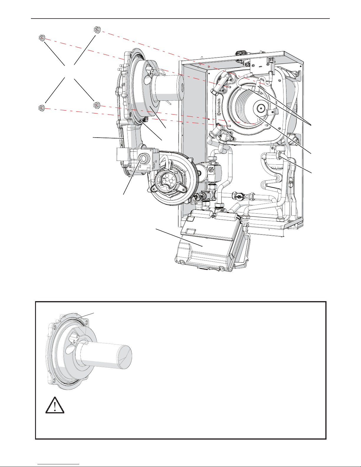
56
AGUADENS
COSMOGAS
8 - MAINTENANCE
Figure 8-3 - Removing the burner fan unit
020009.01.032
CAUTION!!!
If gasket is damaged DO NOT reuse, the heat exchanger door must be replaced.
NOTICE! Gasket is intended for sealing combustion. If damaged DO NOT reuse, the heat exchanger
door must be replaced. Consult factory for replacement heat exchanger door.
GASKET
HEAT EXCHANGER DOOR
G
E
C
B
A
L
F
H
D
G
E
C
B
A
L
F
H
D
020003.01.062
Page 57
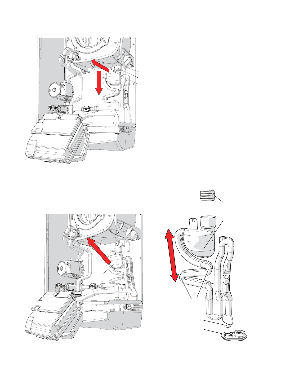
57
AGUADENS
COSMOGAS
8.5 - Condensate siphon
cleaning procedure
For correct cleaning of the collection siphon and the
conveying of the condensate produced by combustion,
operate as follows (refer to the gures 8-4, 8-5 and 8-6):
1.- with the appliance on, open a domestic hot water tap or
taps fully to force the burner to its maximum power and
the level of the liquid present inside the siphon tank “D”
lowers (see gure 8-5);
2.- switch off the appliance and disconnect the electrical
supply;
3.- access the internal components following section 8.2;
4 - remove the burner fan unit following section 8.3;
5 - cover the electric box with a cloth to protect it from any
residues of water inside the siphon to be removed.
6.- slide the support “B” outwards from the holding support;
7.- slide the tank “C” downwards, paying attention to the
fact that it is full of condensate water and this could
escape;
8.- extract the siphon outwards (see gure 8-5) paying
attention to disconnect the collection pipes of the water
coming from the upper part of the appliance and from the
air vent valve.
9.- clean the decanting tank “D”;
10.- re-mount everything in reverse order, paying attention
to the gasket “E”, which is put back in the relevant seat
and that terminal “G” is inserted correctly into seat “H”;
11.- restore the level of liquid inside the siphon following the
procedure in section 6.1.2.
Figure 8-5 - Removing condensate collection
siphon
Figure 8-6 - Condensate collection siphon
H
G
F
D
E
020002.01.030
8 - MAINTENANCE
Figure 8-4 - Removal of the condensate collection
siphon
B
C
A
B
C
A
020003.01.053
DD
020003.01.054
Page 58
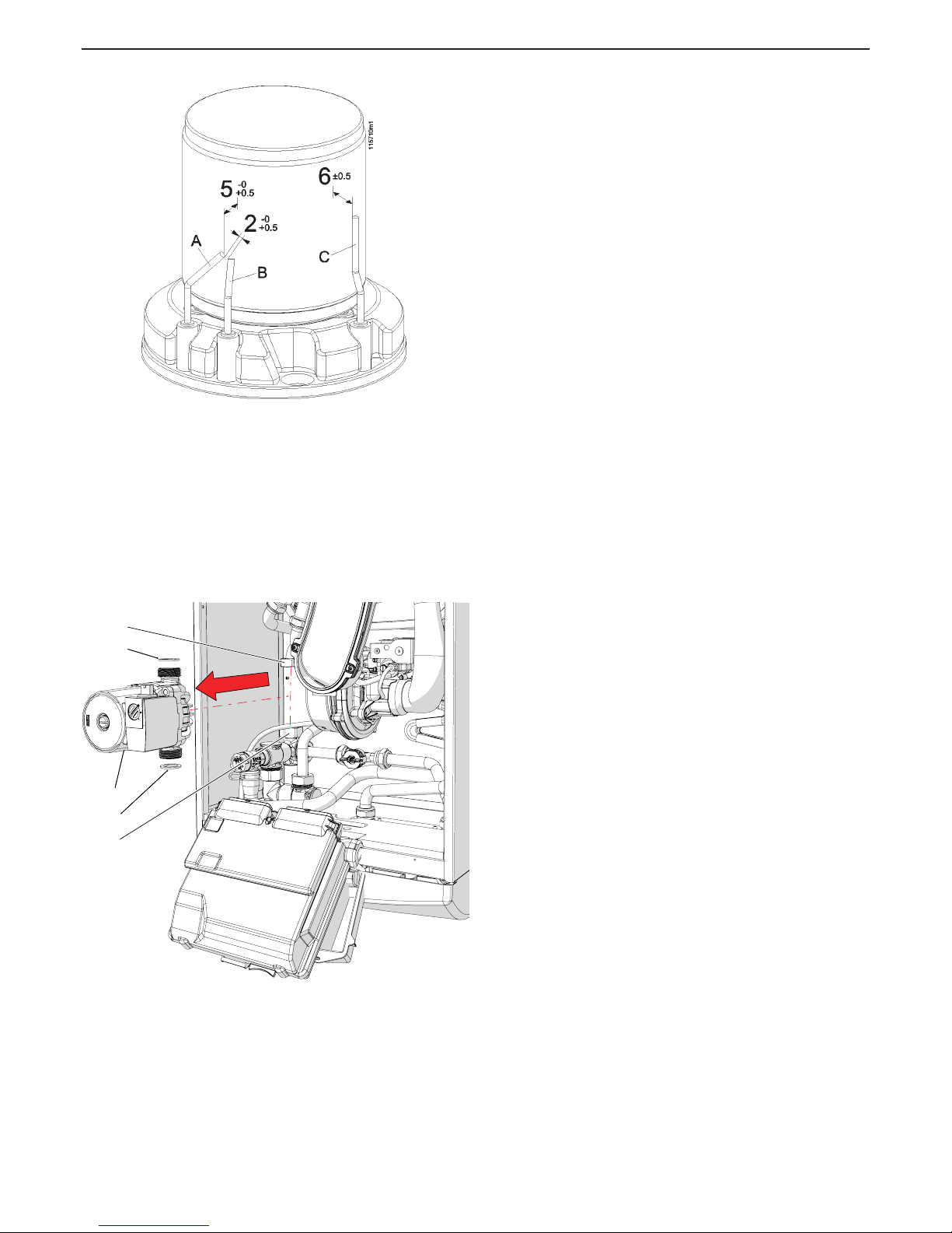
58
AGUADENS
COSMOGAS
8.6 - Ignition and ame
isonising electrode position
For good working order of the appliance, it is indispensable
that the electrodes are positioned correctly (refer to gure
8-7):
- the distance between the ignition electrodes “A” and “B”,
must be between 2,0 and 2,5 mm;
- the distance between the ignition electrodes from the burner
surface must be between 5 and 5,5 mm;
- the distance of the ionisation electrode “C” from the surface
of the burner must be between 5,5 and 6,5 mm.
Figure 8-8 - Replacing the pump motor
8 - MAINTENANCE
Figure 8-7 - positioning the electrodes on the
burner
8.7 - Circulation pump
replacement procedure
Operate as follows if the pump must be replaced (refer to
gure 8-8):
1.- empty the domestic hot water circuit, following the
procedure in section 8.10;
2.- disconnect the electric power supply upstream from the
appliance;
3.- access the components inside the appliance, following
section 8.2;
4.- disconnect the electric cables from the pump body.
5.- loosen the nuts “C”;
6.- extract the pump “B” outwards and replace it.
C
C
A
A
B
C
C
A
A
B
020003.01.051
Page 59
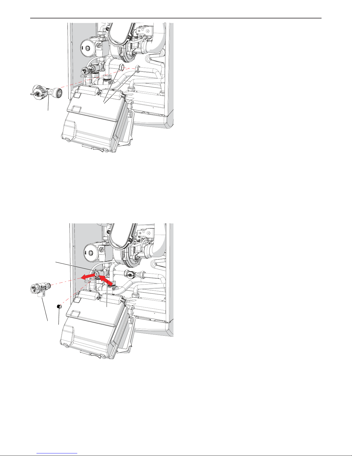
59
AGUADENS
COSMOGAS
Figure 8-9 - Removing the ow meter
8.8 - Domestic water ow meter
replacement procedure
Proceed as follows, making reference to gure 8-9:
1.- empty the domestic hot water circuit, following the
procedure in section 8.10;
2.- disconnect the electric power supply upstream from the
appliance;
3.- access the components inside the appliance, following
section 8.2;
4.- disconnect the cables from the ow meter (detail “B” in
gure 8-9);
5.- unscrew the tightening nuts “A”, paying attention that the
residual water from the pipes does not reach the control
board;
6.- slide the ow meter “B” upwards and replace it.
Figure 8-10 - Removing the safety valve
8 - MAINTENANCE
8.9 - Safety valve
replacement procedure
The safety valve (detail “A” in gure 8-10) protects the
appliance from over pressures. If it has to be replaced,
proceed as follows (refer to gure 8-10):
1.- empty the domestic hot water circuit, following the
procedure in section 8.10;
2.- access the components inside the appliance, following
section 8.2;
3.- disconnect the drain pipe from the valve to be replaced
“A”;
4.- unscrew the lower xing disk “B” of valve “A”;
5.- extract the safety valve “A” upwards and replace it.
ABA
B
020003.01.050
B
A
C
D
B
A
C
D
020003.01.049
Page 60

60
AGUADENS
COSMOGAS
8 - MAINTENANCE
8.10 - Procedure for draining
the water heater
To empty the appliance from the domestic hot water side,
proceed as follows:
1.- close the main cold water supply isolation valve;
2.- open all hot and cold water taps;
3.- make sure that at least one of these is at a height below
the level of the appliance.
8.11 - Fan test mode procedure
Switch-on of the fan only can be generated, accessing the
parameter 2010 situated inside the “Installer menu” (see
section 7.8) and set it on FAn. To go back to normal operating
conditions, set parameter 2010 again to 0FF.
8.12 - Gas burner minimum
and maximum performance
test mode procedure
Appliance operation can be forced to its own minimum,
maximum, adjusted or ignition power. Proceed as follows:
1.- access parameter 2010 found in the “installer menu”
(see section 7.8);
2.- set the parameter 2010 at the following value:
a) LOu to force the appliance to minimum power;
b) Ign to force the appliance to ignition power;
a) HIgH to force the appliance to maximum power;
a) rEg to force the appliance to maximum power.
4.- to end forcing, take the parameter 2010 to the 0FF
value and press the RESET key.
Page 61
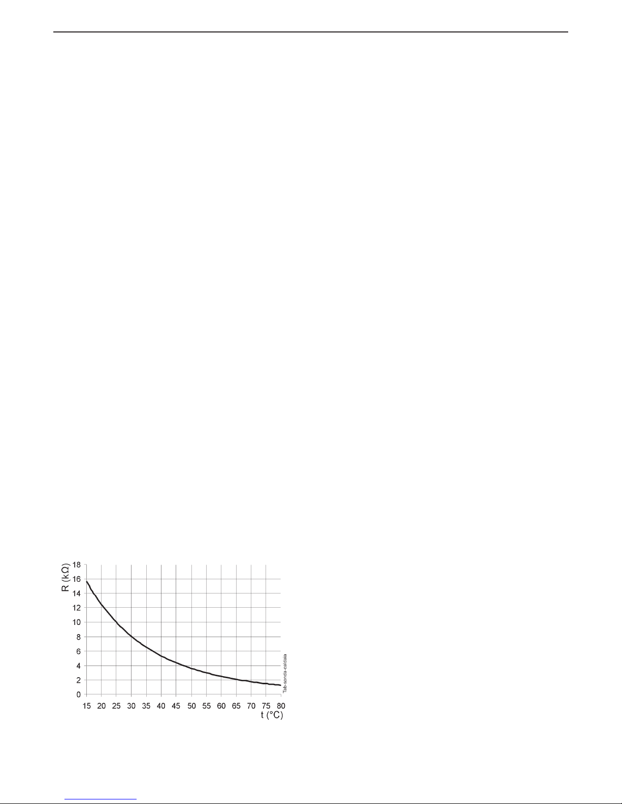
61
AGUADENS
COSMOGAS
Figure 8-11 - Water sensors curve
8.13 - Checking the ionisation current
In any operating status, also during verications of minimum
and maximum power stated in section 8.12, the ionisation
current value can be consulted on parameter 1008 present
in the “User menu” (section 7.7). This value must be between
1,5 and 3 uA (microampere) at minimum power and between
5 and 8 uA at maximum power.
8.14 - Water temperature measurement
sensor testing procedures
The temperature sensors are positioned on the appliances’
exchanger body. The electric resistance existing between
the two contacts of the sensor, must correspond with that
stated in gure 8-11.
The temperature sensors are: 1001, 1002, 1003,
1005, 1006, 1007 and 1014, the positioning of
which can be veried in gures 3-1, 3-2, 3-3 and 3-4.
Page 62
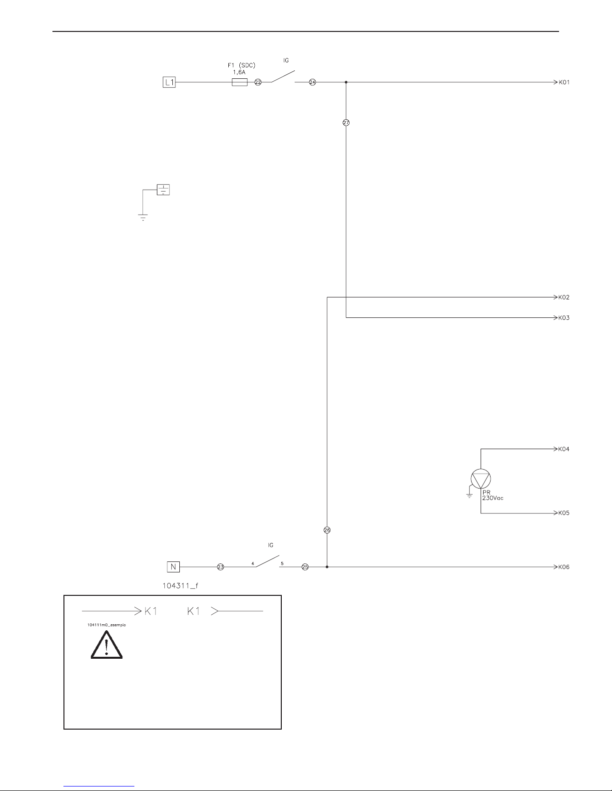
62
AGUADENS
COSMOGAS
8.15 - Operational wiring diagram
Figure 8-12 - Operational wiring diagram
ATTENTION !!! To consult
the wiring diagram correctly,
references K are given
followed by a number (see example
above) to identify the correct followon of the cables in the next page.
8 - MAINTENANCE
1001 - D.H.W. outlet temperature sensor 1
1002 - D.H.W. outlet temperature sensor
1002 (SB) - Storage tank sensor (on request)
1005 - D.H.W. outlet temperature safety sensor 2
1006 - Exhaust ue sensor 1
1007 - Cold water inlet sensor
1014 - Exhaust ue safety sensor 2
CM - Appliance control unit and ame control
CR - Remote control CR01
CR04 - Remote control CR04
DSP - Display
EA - Ignition electrode
Page 63
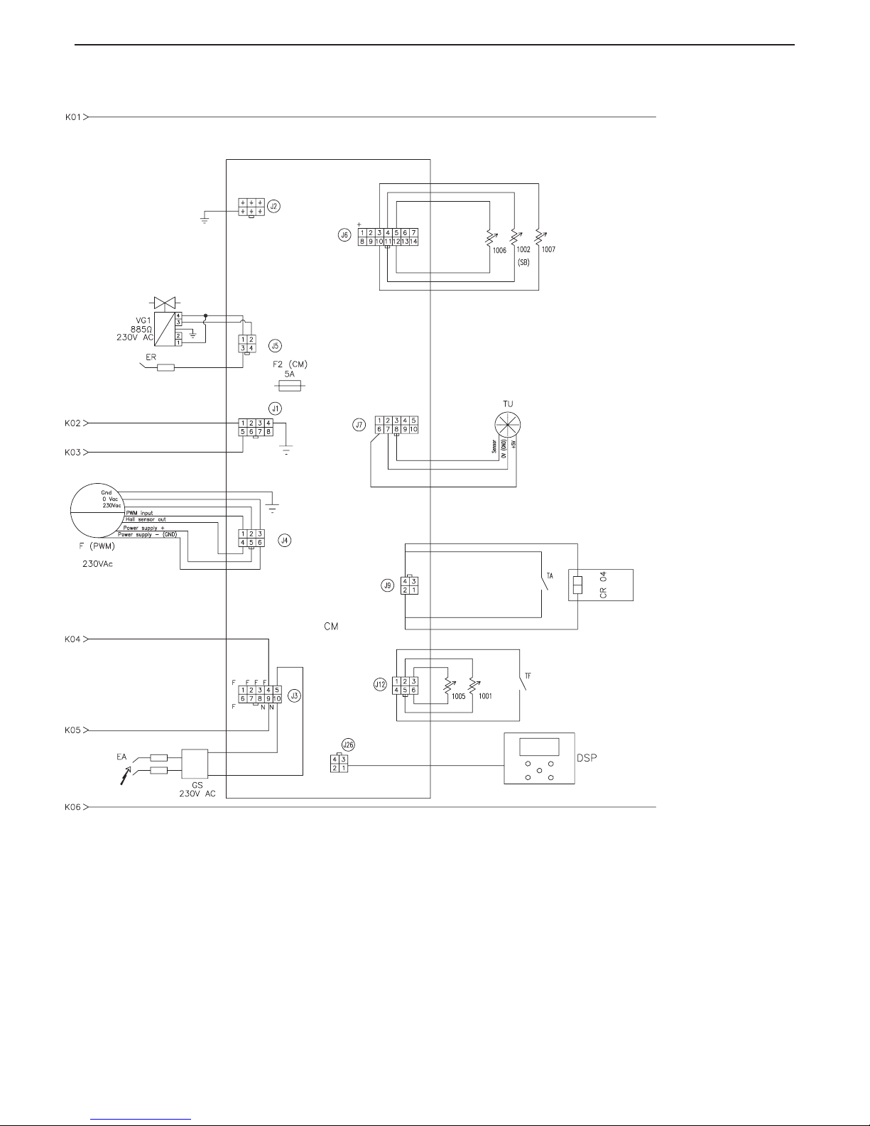
63
AGUADENS
COSMOGAS
8 - MAINTENANCE
ER - Detection electrode
F (PWM) - PWM fan
F (BCU) - 5A fuse
F1 (SDC) - 1.6A power supply fuse
PB - Storage tank load aux. pump (on request)
PR - Recirculation Pump
GS - Spark generator
IG - Master switch
J1 - 8 pin Molex connector
J12- 6 pin Molex connector
J2 - 6 pin Molex connector
J26- 4 pin Molex connector
J3 - 10 pin Molex connector
J4 - 6 pin Stelvio connector
J5 - 4 pin Molex connector
J6 - 14 pin Molex connector
J7- 10 pin Molex connector
J9- 4 pin Molex connector
PB - Storage tank pump (on request)
SDC- Connection board
TF- High limit ue gas temperature fuse
TU - Domestic hot water ow meter
VG1- Gas Valve
Page 64
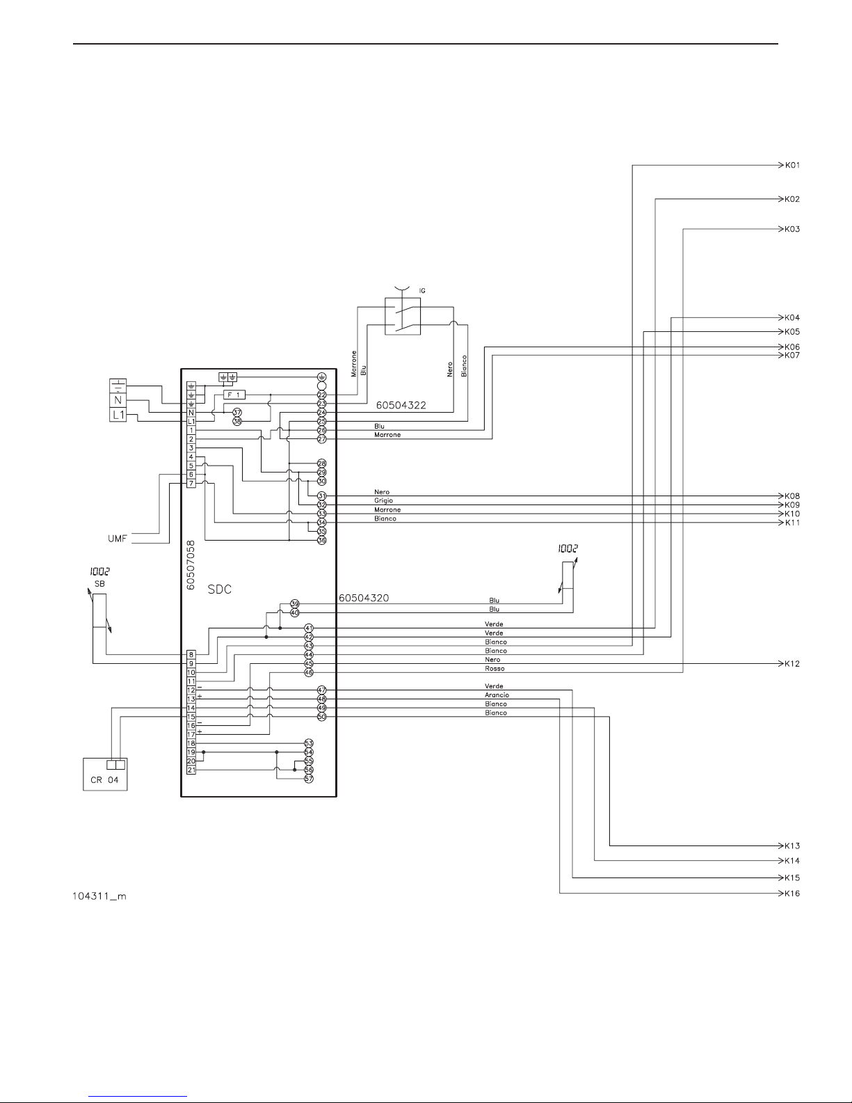
64
AGUADENS
COSMOGAS
8.16 - Multi-wire wiring diagram
Figure 8-13 - Multi-wire wiring diagram
Key - see key gure 8-12
8 - MAINTENANCE
COLOR OF DIAGRAM CABLE
ARANCIO = ORANGE
BIANCO = WHITE
BLU = BLUE
GIALLO = YELLOW
GIALLO/VERDE = YELLOW/GREEN
GRIGIO = GREY
MARRONE = BROWN
NERO = BLACK
ROSSO = RED
VERDE = GREEN
Page 65
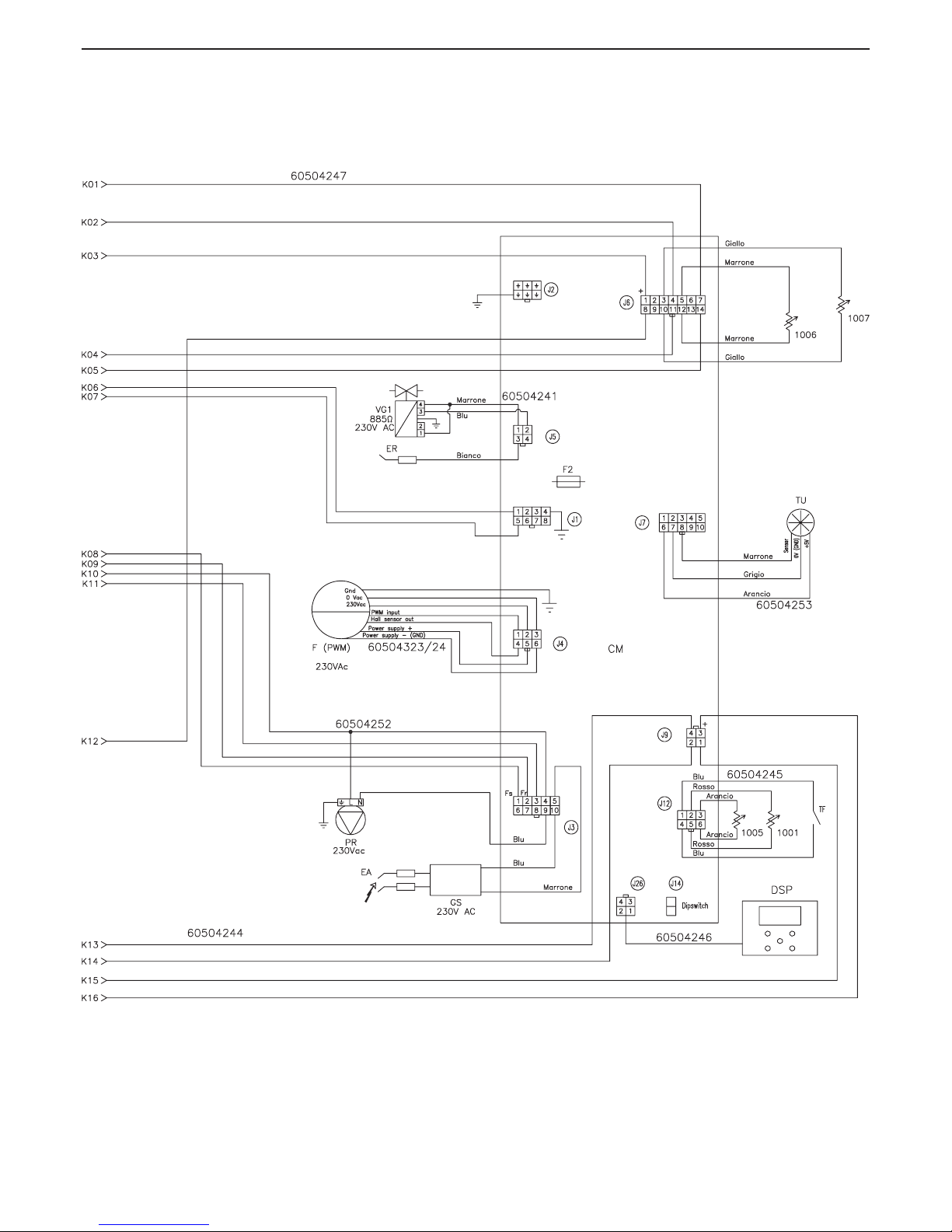
65
AGUADENS
COSMOGAS
8 - MAINTENANCE
Page 66
66
AGUADENS
COSMOGAS
9 - TECHNICAL DATA
TECHNICAL DATA UM AGUADENS 16 AGUADENS 22 AGUADENS 37
Type (Type of exhaust ue/combustion air intake) B23;C13;C33;C43;C53;C63;C83;C93
Category II2H3P II2H3P II2H3P
CE type certicate (PIN) 0476CQ1097 0476CQ1097 0476CQ1097
Max. heat input NET (GROS) kW 25,5 (28,3) 32,0 (35,5) 57,8 (64,2)
Min. heat input NET (GROS) kW 3,2 (3,6) 6,0 (6,7) 12,0 (13,3)
Max. useful heat output kW 27,0 33,5 60,9
Efciency at max heat output NET (GROS) % 106 (96) 105 (95) 107 (96)
Min. heat output kW 3,30 6,14 12,85
Efciency at min heat output NET (GROS) % 103 (93) 102 (92) 107 (96)
Gas ow rate
G20 m
3
/h 2,70 3,38 6,11
G31 Kg/h 1,98 2,48 4,49
Gas supply pressure
G20 mbar 20 20 20
G31 mbar 37 37 37
Gas supply minimum pressure
G20 mbar 15 15 15
G31 mbar 15 15 15
Gas supply maximum pressure
G20 mbar 45 45 45
G31 mbar 45 45 45
D.H.W. adjustment range °C 40-75 40-75 40-75
D.H.W. ow rate (Δt 30°C) l/min 13,0 16,1 29,5
Domestic circuit maximum pressure bar 10 10 10
Domestic circuit minimum pressure bar 1 1 1
Minimum water ow l/min 2,5 2,5 2,5
Rated power supply voltage V 230 230 230
Rated power supply frequency Hz 50 50 50
Absorbed electric power W 169 162 235
Electric protection degree IPX4D IPX4D IPX4D
Exhaust ue and air intake pipe diameter (split) mm 80 80 80
Exhaust ue pipe max. length (split) (80) m 20 12,5 5
Air intake pipe max. length (split) (80) m 20 12,5 5
Exhaust ue pipe diameter (coaxial) mm 60/100 60/100 80/125
Exhaust ue pipe max. length (coaxial) m 10 10 10
Equivalent length of a bend m Curva a 45° = 0.5m, curva a 90° =1m
Weighted CO (0% O2 with natural gas) (EN26:2015) GROS ppm 11 19 10
Weighted NOx (0% O2 with natural gas) (EN26:2015) GROS G20 mg/kWh 20 29 16
Weighted NOx (0% O2 with natural gas) (EN26:2015) GROS G31 mg/kWh 24 34 20
CO2 (%) at minimum/maximum power
G20 % 8,5/9,0 8,5/9,0 8,3/8,7
G31 % 10/10,5 10/10,5 10,8/10,1
Exhaust ue gas maximum temperature at appliance outlet °C 90 90 90
Mass ow rate of exhaust ue gases kg/h 41,9 52,5 97,8
Head available at exhaust ue outlet Pa 60 60 60
Exhaust ue gas maximum temperature for overheating °C 90 90 90
Max. negative pressure in exhaust ue system Pa 60 60 60
Condensate maximum ow rate l/h 3,2 4,0 7,2
Condensate average acidity PH 4 4 4
Operating environment temperature °C 0 ; +50 0 ; +50 0 ; +50
Weight of the appliance kg 36 36 48
Page 67
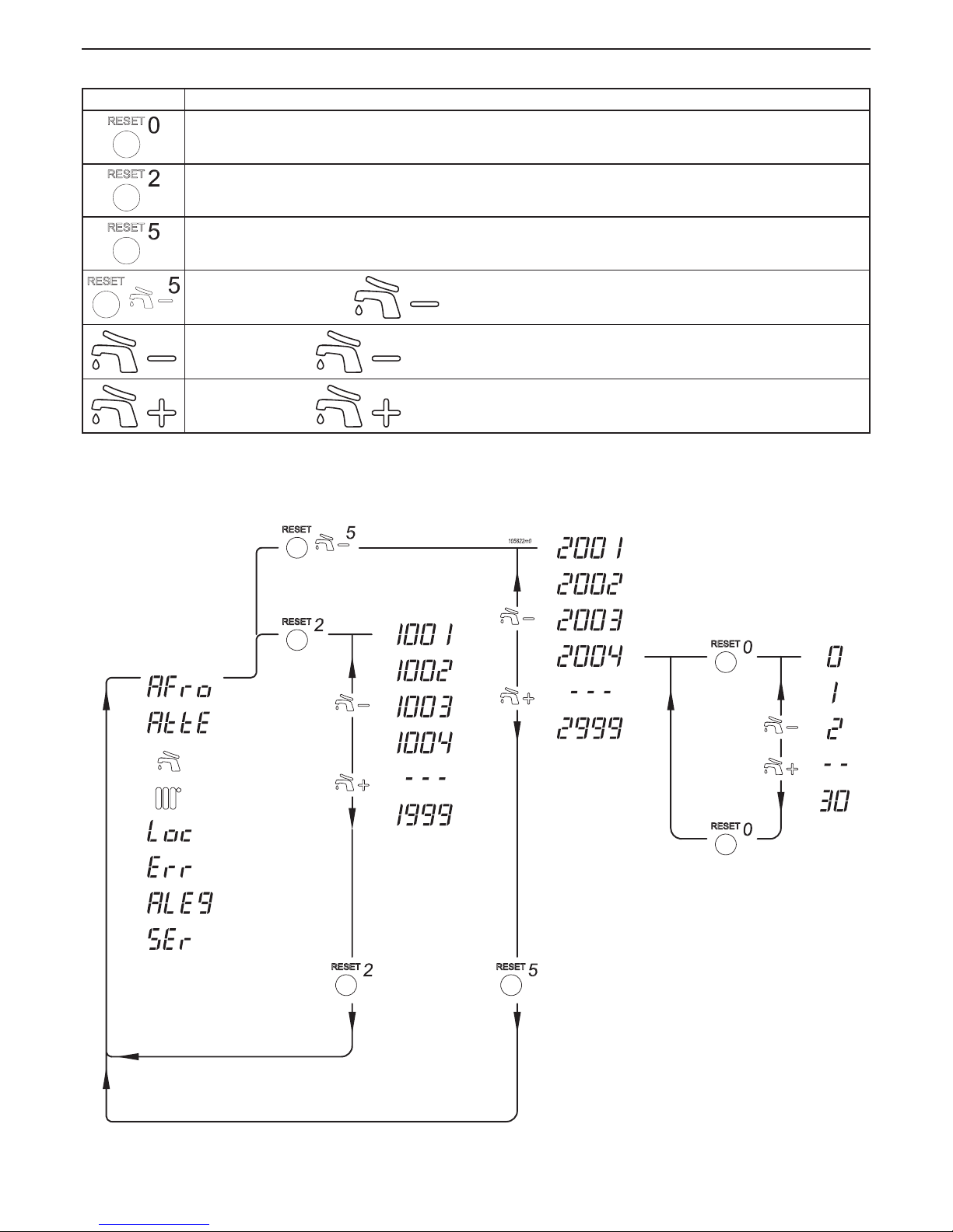
67
AGUADENS
COSMOGAS
10 - COMMAND MENU DIAGRAM
Symbol Description
Press and release the RESET key
Hold the reset key down for a time in seconds, indicated by the number (2)
Hold the reset key down for a time in seconds, indicated by the number (5)
Hold down the RESET and key simultaneously for a time in seconds, indicated by the number
Press and release the key
Press and release the key
Pa rameters th at
can be displayed in
normal operating
conditions
(see section 7.9)
Use menu
parameters
(see section 7.7)
Installer
menu
parameters
(see section
7.8)
Installer
menu
parameters
(see section
7.8)
Us e me nu acce ss
(see section 7.7)
Installer menu access
(see section 7.8)
Return to normal operation
Return to normal operation
Figure 10-1 - Command menu diagram
Key for gure 10-1
Page 68
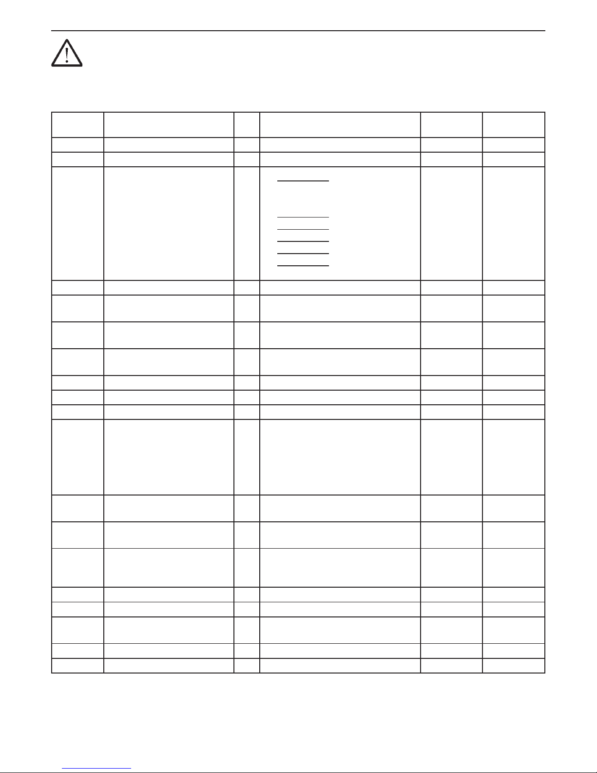
68
AGUADENS
COSMOGAS
ATTENTION !!!
The modication of these parameters could cause the appliance, and therefore the plant, to malfunction.
For this reason only a technician that has the awareness and in-depth knowledge of the appliances can modify
them.
To access this menu, move the microswitch as stated in gure 6-6 detail “B”.
11 - ENGINEERS TEST MODE
Parameter Parameter Description M.U. Setting range
Factory value
Customised
value
3001 Cascade adress (N/A)
(N/A)
(N/A) 0 (N/A)
3002 Selection type From 50 to 55 See gure 6-8
3012
Domestic hot water operating
mode
/
0 = DO NOT USE;
1 = Storage tank with temperature sensor;
2 = Storage tank with thermostat;
3 = DO NOT USE;
4 = DO NOT USE;
5 = DO NOT USE;
6 = DO NOT USE;
7 = DO NOT USE;
8 = Instantaneous water heater;
8
3013 Plant ll automatic valve (N/A)
(N/A)
(N/A) 0 (N/A)
3014
Instantaneous domestic hot
water pre-heat
/
OFF = No pre-heat
ON = With pre-heat
OFF (N/A)
3015
Maximum central heating
temperature (N/A)
(N/A)
(N/A) 80 (N/A)
3016
Minimum central heating
temperature (N/A)
(N/A)
(N/A) 30 (N/A)
3017 Pre-heat mode (N/A)
(N/A)
(N/A) 0 (N/A)
3018 Minimum DHW temperature
°C
From 30 to 75 40
3019 Maximum DHW temperature
°C
From 30 to 75 60
3020
Domestic hot water ow rate
sensor
/
0 = B;
1 = DN 8; (model 16)
2 = DN 10;
3 = DN 15; (models 22 and 37)
4 = DN 20;
5 = DN 25;
1 (16)
3 (22)
3 (37)
3021
2nd Exhaust ue sensor (1014)
(N/A)
(N/A) (N/A)
0 (N/A)
3022
Central heating minimum
pressure (N/A)
(N/A)
(N/A) 0,8 (N/A)
3023 Water pressure sensor
/
0 = Disabled;
1 = Enabled;
0 (16)
0 (22)
0 (37)
3033 Modulating pump (N/A)
(N/A)
(N/A) 0 (N/A)
3034 Modulating pump delta T target (N/A)
(N/A)
(N/A) 15 (N/A)
3040 Antilegionella for water heater
/
ON = Antilegionella enable
OFF = Antilegionella disabled
ON
3041 Tank supply temperature increase
°C
From 0 to 30 0
3042 Minimal water ow
l/min
From 0 to 25,5 2,5
N/A = Not applicable
Page 69
69
AGUADENS
COSMOGAS
The undersigned COSMOGAS S.r.L., with Registered Ofce in via L. Da
Vincin° 16 - 47014 Meldola (FC) ITALY,
DECLARES
under its own responsibility that the product:
subject of this declaration, is compliant with the model described in the
type Test Certicate, issued by the notied body Kiwa Cermet Italia S.p.A.,
whose references are shown in the table in the TECHNICAL FEATURES
section under “CE-type certicate (PIN)” and fulls the requirements of
the following Directives: Gas Appliances, (2009/142/EC), Performance,
(92/42/EEC modied by EU Reg. 813/2013), Low Voltage, (2014/35/EU),
Electromagnetic Compatibility,
(2014/30/EU).
Product surveillance is done by the notied body according to form “C”.
(The warranty number is the same as the serial number)
This declaration is issued as established by the aforementioned Directives.
Meldola (CFC) ITALY, (Date of manufacture).
DATE OF MANUFACTURE
WARRANTY N°
GAS BOILER MODEL
12 - CE DECLARATION OF CONFORMITY
________________________
Alessandrini Arturo
General Manager
Page 70

Page 71

Page 72

 Loading...