

Page 1

3
OPERATOR'S AND
PARTS MANUAL
BPF SERIES
FLAIL MULCHER
Page 2

4
Congratulation for purchasing your new COSMO BULLY Flail Mulcher!
This machine has been designed and manufactured following all safety and quality requirements needed
for a safe and satisfactory use over time.
A careful reading of this manual will permit you to familiarize with your new equipment and will provide
you all the tools needed to use it safely.
Proper maintenance and knowledge of the safety rules of use will allow obtaining the best performance
and long service life of the machine.
The Safety Alert Symbol used throughout this manual and on safety decals of the
machine indicates the presence of potential hazard to the operator. When you see
this symbol, be alert and carefully read the message that follows it.
The Safety Alert Symbol is used in conjunction with following Signal Words, according to the
degree of possible injuries that may result operating the implement:
DANGER
Indicates an imminently hazardous situation that, if not avoided, will result in death or serious injury.
WARNING
Indicates a potentially hazardous situation that, if not avoided, could result in death or serious injury, and
includes hazards that are exposed when guards are removed. It may also be used to alert against unsafe
practices.
CAUTION
Indicates a potentially hazardous situation that, if not avoided, may result in minor or moderate injury. It
may also be used to alert against unsafe practices.
IMPORTANT
Indicates instructions or procedures that, if not observed, can cause damage to equipment or environment.
NOTE
Indicates helpful information.
READ, UNDERSTAND, and FOLLOW the safety messages following the Safety Alert Symbol and Signal
Words. Failure to comply with safety messages could result in serious bodily injury or death.
Page 3

5
TO THE PURCHASER
This manual contains valuable information about COSMO BULLY FLAIL MULCHER. It
has been carefully prepared to give you helpful suggestions for operating, adjusting,
servicing repair parts.
Keep this manual in a convenient place for quick and easy reference. Study it carefully.
You have purchased a dependable and sturdy Flail Mulcher, but only by proper care
and operation can you expect to get the service and long life designed and built into
it.
RIGHT-HAND AND LEFT-HAND sides are determined by watching from the tractor side.
Sometime in the future, your Flail Mulcher may need new parts to replace those are
worn or broken. If so, go to nearest COSMO BULLY dealer and provide him with the
model and part number.
Customer information
Name ____________________________________________________________
Purchased from_____________________________________________________
Purchased date______________________________________________________
Model No.__________________________________________________________
Serial No.___________________________________________________________
Page 4

6
TABLE OF CONTENT
1. ABOUT THIS MANUAL 6
2. INTRODUCTION 6
2.1. MACHINE IDENTIFICATION 6
2.2. INTENDED USE 7
2.3. MAIN PARTS DESCRIPTION 8
2.4. CONFIGURATION 9
2.5. TECHNICAL SPECIFICATION 10
3. SAFETY 11
3.1. GENERAL SAFETY INSTRUCTIONS 11
3.2. EQUIPMENT SAFETY INSTRUCTIONS 12
3.3. OPERATING SAFETY INSTRUCTIONS 13
3.4. TRANSPORTING SAFETY INSTRUCTIONS 15
3.5. MAINTENANCE SAFETY INSTRUCTIONS 15
3.6. STORAGE SAFETY INSTRUCTIONS 16
3.7. SAFETY LABELS 16
4. SET UP 20
4.1. CONNECTING TO THE TRACTOR 20
4.2. DRIVELINE INSTALLATION 21
4.3. TRACTOR-FLAIL MULCHER STABILITY 23
5. OPERATING 24
_ 5.1. START-UP 24
_5.2. OPERATING INSTRUCTIONS 25
5.3. ADJUSTMENTS _ 25
5.4. STOPPING AND DISCONNECTION __ 31
5.5. TRASPORTATION 31
6. MAINTENANCE 32
6.1. ROTOR TOOLS REPLACEMENT 32
6.2. GEARBOX LUBRICATION 33
6.3. ROTOR BEARINGS LUBRICATION 34
6.4. ROLLER BEARINGS LUBRICATION 35
6.5. DRIVE BELTS REPLACEMENT 35
6.6. DRIVESHAFT MAINTENANCE 35
7. STORAGE 36
8. SCRAPING 36
9. TROUBLESHOOTING 37
10. TORQUE VALUES TABLE 37
11. WARRANTY 38
12. SPARE PARTS 41
13. “EC” DECLARATION OF CONFORMITY 64
Page 5
7
1. ABOUT THIS MANUAL
The operator must read the manual for a correct understanding of the hazards that may present when
operating the Flail Mulcher, as well as for obtaining optimum performance from the machine.
The manual is part of the machine, it must be kept in good condition and remain with the machine even in
case of resale, until its demolition. In case of loss or damage, request a new copy to the Manufacturer or
your Dealer.
The information, descriptions and illustrations in this manual describe the state of the product at the time
of its publication, and may not reflect the product in the future.
The Manufacturer reserve the right to make design improvements or changes in specifications without
incurring any obligation to install them on units previously sold.
Text, illustrations and drawings of this manual cannot be disclosed or transmitted, in whole or in part, to
third parties without the written permission of the Manufacturer. All rights are reserved.
2. INTRODUCTION
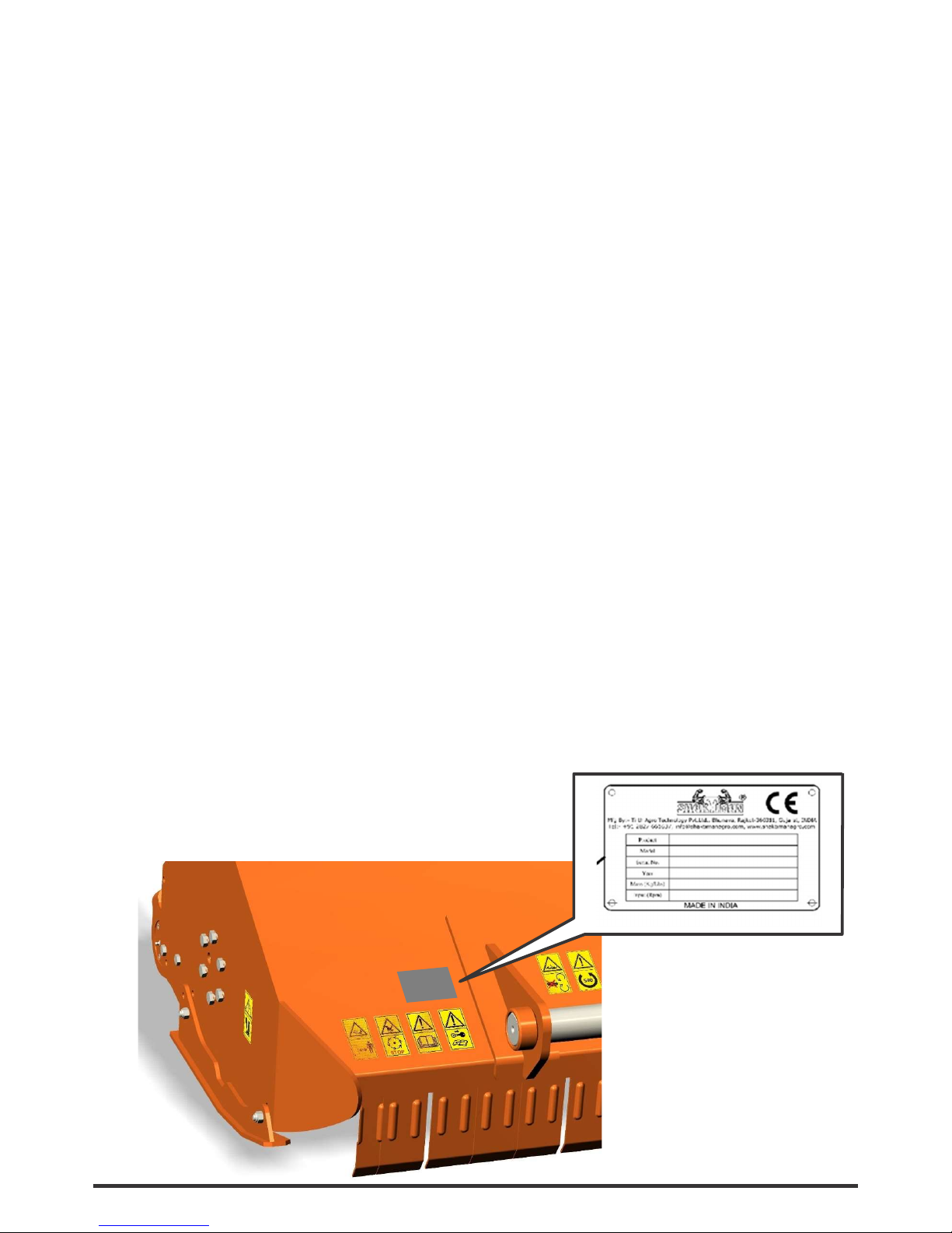
2.1. MACHINE IDENTIFICATION
Each Flail Mulcher is provided with a plate for unique identification (see the position in the picture below),
showing the CE
marking together with the following information:
• Manufacturer name and address
• Type of machine (“TYPE”)
• Model of machine (“MODEL”)
• Serial number (“SERIAL No.”)
• Construction year (“YEAR”)
• Machine weight (“MASS”)
It’s recommended to note down all data shown on the plate.
Any request for assistance or information regarding the machine must be directed to the Manufacturer or
Dealer always referring to the model and serial number as shown on the plate affixed to the machine.
Page 6

8
2.2. INTENDED USE
The BPF Flail Mulcher is designed specifically for cutting grass and for shredding fibrous wood stalks, corn
and branches up to a diameter of 7 cm (depending on the type of blade used).
The Flail Mulchers are designed to be mounted on tractors equipped with a hydraulic lift and universal
three-point hitch that can support the implement weight, and driven by the power of the tractor through
the PTO driveshaft.
The tractors used to operate the Flail Mulcher must have the following requirements:
Hitch Category: 3-point hitch, I / II Category standard
PTO: 540 RPM, 6-spline, 1 3/8 Z6
Horsepower: 50-100 HP
DANGER
Any use of the machine other than the intended use is non-intended use and is to be considered as
unauthorized and dangerous. The manufacturer assumes no liability for damage resulting from nonintended use.
Page 7
9
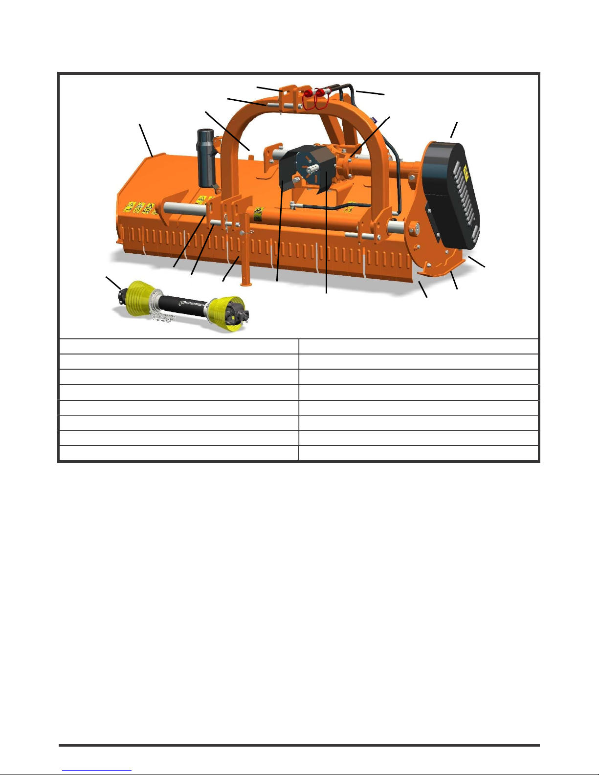
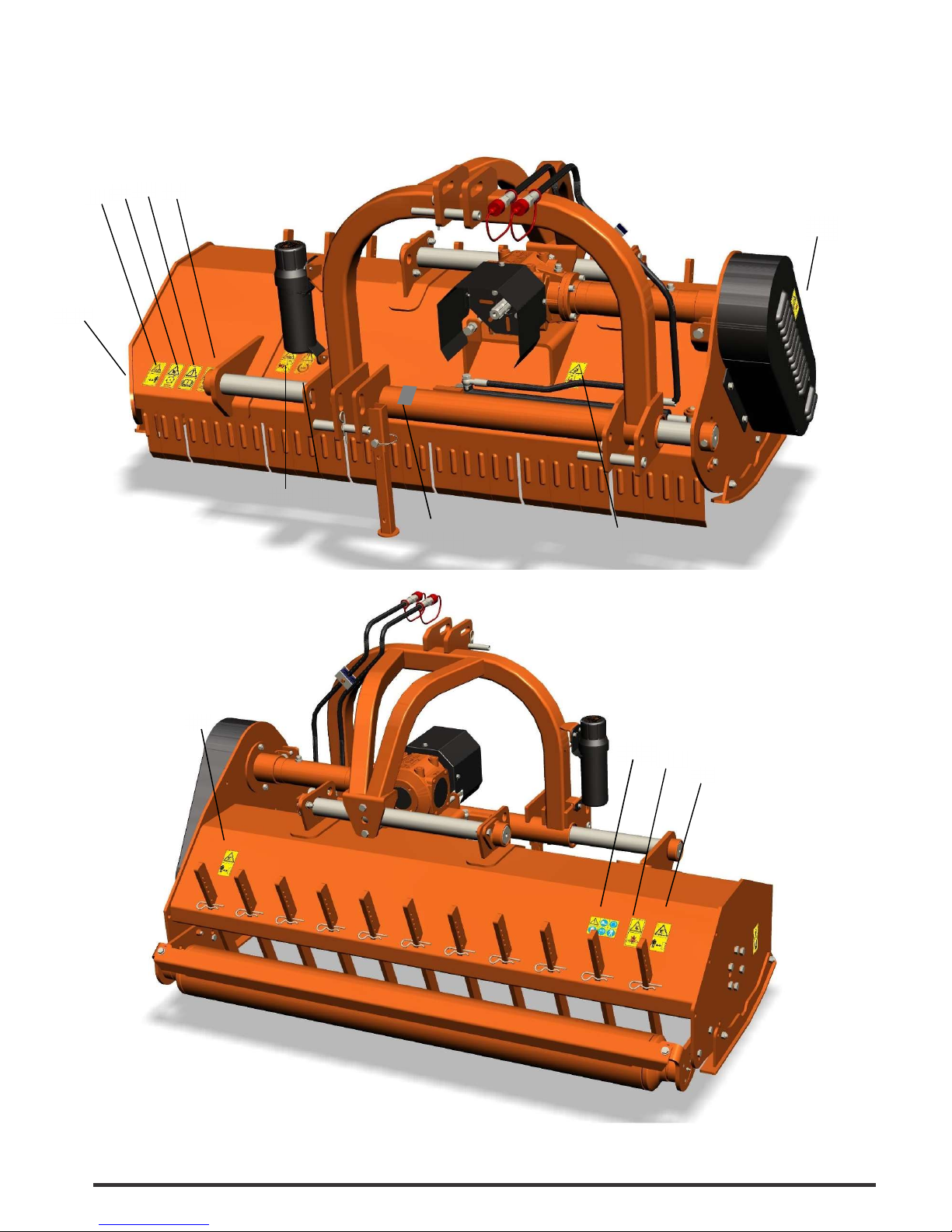
2.3. MAIN PARTS DESCRIPTION
1. Flail Mulcher frame 9. Side transmission case
2. Lower hitch 10. Rakes
3. Lower hitch pin 11. Shredding Chamber
4. Upper hitch pin 12. Roller
5. Upper hitch 13. Parking stand
6. Input Shaft Cover 14. Side skid
7. Implement Input Shaft 15. Hydraulic hoses
8. Gearbox with a free wheel inside
NOTE
To make the illustrations clear, some images of this manual may show machines missing some safety
components. NEVER operate with the safety components (e.g. safety devices and barriers) removed.
1
2
3
4
5
6
7
8
9
10
11
13
14
15
12
13
Page 8
10
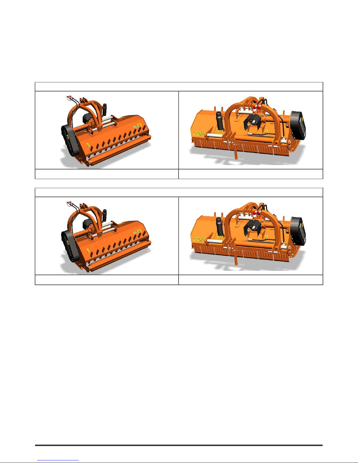
2.4. CONFIGURATIONS
The BPF Flail Mulcher can be set in different configurations.
The standard configuration can be changed by applying one or more optional parts, listed below:
STANDARD CONFIGURATION
• Mobile arc with hydraulic cylinder
• Hammers
OPTIONAL CONFIGURATION
• Mobile arc without hydraulic cylinder
M o b i l e a r c w i t h o u t
s c r e w
Page 9

11
2.5. TECHNICAL SPECIFICATIONS
BPF
180 200 225
Overall size L x W x H
mm
1194 X 2000 X 990
(47 X 79 X 39)
1194 X 2200 X 990
(47 X 87 X 39)
1194 X 2450 X 990
(47 X 96 X 39)
(inch)
Working width mm (inch) 1780 (70) 1980 (78) 2230 (88)
Recommended
tractor HP
HP 50-100 50-100 50-100
3 Point Hitch Type Cat-II Cat-II Cat-II
No. of blades Nos 48 60 60
No. Of Hammer Nos 16 20 20
PTO input speed Rpm 540 540 540
Rotor speed Rpm 2146 2146 2146
Side transmission 4 Belt XPB type 4 Belt XPB type 4 Belt XPB type
Side shift (max) mm 337 437 467
Rotor diameter mm 170 170 170
Rotor swing diameter mm 410 410 410
Approx. Weight Kg/lbs 680(1500) 735(1620) 800(1763)
Page 10

12
3. SAFETY
Proper use of the equipment, a strict observance of the safety messages listed below and application of all
reasonable practices to avoid any risks, prevents accidents or injury, allows the machine to work better
and longer, and minimize the risk of failures.
The manufacturer assumes no liability for any damage resulting from not applying the behavioral rules
indicated into the manual.
3.1. GENERAL SAFETY INSTRUCTION
DANGER
The machine must be used only by authorized and well trained operators. The operator must have read
and understood the instructions of this manual, it must make adequate preparation for the proper use of
the machine and must hold a driving license. In case of doubt about the use of the machine and/or the
interpretation of this manual, the operator must contact the Manufacturer or the Dealer.
WARNING
The manual must always remain with the machine. In case of loss or damage, request a new copy to the
Manufacturer or your Dealer.
WARNING
Follow strictly the rules prescribed by the safety pictograms applied to the machine.
WARNING
Be sure that all safety pictograms are legible. If pictograms are worn, they must be replaced with others
obtained from the Manufacturer, and placed in the position indicated by this manual.
DANGER
Before using the machine, make sure that all safety devices are installed and in good working conditions.
In case of damages of shields, replace them immediately.
DANGER
Is absolutely forbidden to remove or alter safety devices.
DANGER
Before starting, and during operation of the Flail Mulcher, make sure there are no people or animals in
the opera- tion area: the machine can project material from the back, with risks of serious injury or
death.
DANGER
Pay maximum attention to avoid any accidental contact with rotating parts of the machine.
DANGER
During operation, adjustment, maintenance, repairing or transportation of the machine, the operator must
always use appropriate Personal Protective Equipment (PPE).
Page 11

13
DANGER
Do not operate the implement while wearing loose fitting clothing that can give rise to entanglement in
parts of the machine.
DANGER
Do not operate the implement when tired, not in good condition or under the influence of alcohol or drugs.
CAUTION
If the use of the machine is required at night or in conditions of reduced visibility, use the lighting system
of the tractor and possibly an auxiliary lighting system.
3.2. EQUIPMENT SAFETY INSTRUCTION
WARNING
Use the Flail Mulcher for its intended purpose only. Improper use can damage the Flail Mulcher and cause
serious injury to persons, animals, or death.
DANGER
The machine should be used by a single operator driving the tractor.
WARNING
Any unauthorized modification of the machine may cause problems in safety and relieves the Manufacturer
from any liability for damages or injuries that may result to operators, third parties and objects.
WARNING
Before using the machine, familiarize yourself with its controls and its working capacity.
WARNING
Do not leave the Flail Mulcher unattended with tractor engine running.
WARNING
Do not operate Flail Mulcher on too muddy, sandy or rocky soils.
WARNING
Keep the machine clean from debris and foreign objects which may damage functioning or cause injury.
WARNING
Do not use the machine if the category of the connecting pins of the Flail Mulcher does not match that of
the tractor hitch system.
WARNING
Do not use the machine with missing bolts, screws, pins or safety pins, safety guards etc.
Page 12

14
WARNING
Never use the machine to transport or lift people, animals or objects.
WARNING
Make certain, by adding front ballast, that at least 20% of the total weight (tractor, implement and ballast)
is on the front axle of the tractor, to ensure stability.
WARNING
Before engaging the tractor PTO, make sure the tractor PTO speed is set as required for the Flail
Mulcher (540 rpm). Do not over speed PTO or machine breakage may result.
DANGER
Do not operate the Flail Mulcher if the driveshaft is damaged. The driveshaft could be subject to
breakage during operation, causing serious injury or death. Remove the driveshaft and replace it with an
undamaged.
WARNING
With Flail Mulcher disconnected from tractor, rest the driveline on the provided support of the Flail Mulcher.
3.3. OPERATING SAFETY INSTRUCTION
WARNING
Before using the machine, be sure to have cleared the operating area from obstacles (stones, branches,
debris, etc...). Mark all the obstacles that cannot be eliminated (e.g. by means flags).
DANGER
Never engage the tractor PTO in the presence of people close to the driveshaft. The body, hair or clothing
of a person can get caught in rotating parts, causing serious injury or death.
DANGER
Before engaging the PTO and during all operations, make sure that no person or animal is in immediate
area of action of the machine. Never use the Flail Mulcher if people are in his working area.
DANGER
It’s absolutely forbidden to stand near the Flail Mulcher with moving parts.
WARNING
The operator must operate machine lifting/lowering only from the driving seat of the tractor. Do not perform lifting maneuvers on side or behind the tractor.
WARNING
Before making changes in direction, turns or going in reverse, slightly lift the Flail Mulcher from the
ground after disengaging the power take-off, to avoid damage to the machine.
Page 13

15
DANGER
In presence of steep slopes (greater than 15 degrees) the tilling action may cause instability of the tractor
with risk of serious injury or death hazard. Consult the manual for the tractor to determine the maximum
slope that the tractor is able to deal with.
DANGER
Always disengage the PTO before raising the Flail Mulcher, and never engage the PTO with the Flail
Mulcher in the raised position. The machine might throw objects at high speed, causing serious injury or
death.
WARNING
Never leave the driver’s seat when the tractor is turned on. Before leaving the tractor, lower the Flail Mulcher
to
the ground, disengage the PTO, insert the parking brake, stop engine and remove the key from the control
panel.
DANGER
The PTO shields of tractor and implement side, the driveshaft shielding and the driveshaft retaining chains
must be properly installed and in good condition, to avoid risk of entanglement with serious injury or death.
DANGER
Before engaging the PTO of the tractor, always make sure that the driveshaft is mounted in the correct
direction, and that its clamping elements are properly connected both to tractor side and to Flail
Mulcher side.
WARNING
Stop operating immediately if blades strike a foreign object. Repair all damage and make certain rotor and
blades are in good condition before resuming operation.
WARNING
Always disengage the tractor PTO when the driveshaft exceed an angle of 10 degrees up or down while
operating. An excessive angle with driveshaft rotating can break the driveshaft and cause flying projectiles.
CAUTION
Prolonged use of the Flail Mulcher can cause overheating of the gearbox. Do not touch the gearbox during
use and immediately after, it could be extremely hot and cause severe burn.
WARNING
All adjustment operations on the Flail Mulcher must be performed by qualified and trained operators, with
the tractor engine off, the PTO disengaged, the Flail Mulcher lowered to the ground or on security stands,
the ignition key off and the parking brake set.
Page 14

16
3.4. TRANSPORTING SAFETY INSTRUCTION
WARNING
Before transporting the machine, determine the stopping characteristics of the tractor and implement.
WARNING
Transport only at speeds where you can maintain control of the equipment.
WARNING
When driving on roads, the implement must be in transport position adequately raised from the road surface, with tractor lifting hydraulics locked so that the Flail Mulcher cannot be lowered accidentally.
DANGER
The implement may be wider than the tractor. Pay attention during transporting to persons, animals or
obstacles exposed.
WARNING
When turning, use extreme care and reduce tractor speed.
WARNING
Do not operate the tractor with weak or faulty brakes or worn tires.
CAUTION
Always use tractor lighting system and auxiliary lighting system for an adequate warning to operators of
other vehicles, especially when transporting at night or in conditions of reduced visibility.
PERICOLO
In case is required the lifting of the machine, make sure that the lifting device chosen is suitable to perform
the operation safely, and use only the lifting points prescribed on Flail Mulcher.
3.5. MAINTENANCE SAFETY INSTRUCTION
WARNING
All maintenance and repairing operations must be performed by qualified and trained operators, with the
tractor engine off, the PTO disengaged, the Flail Mulcher lowered to the ground or on security stands, the
ignition key off and the parking brake set.
WARNING
Perform repairs and replacements necessary to the machine using only original spare parts provided by the
manufacturer or your Dealer.
DANGER
Perform maintenance operations always using appropriate Personal Protective Equipment (protective eye
glasses, hard hat, hearing protection, safety shoes, overall and work gloves, filter mask).
Page 15

17
CAUTION
Before any maintenance operation, make sure that the parts which may become hot during use (gear box)
have cooled.
WARNING
Do not perform repairs that you do not know. Always follow the manual instructions and in case of doubt
contact the Manufacturer or your Dealer.
DANGER
Do not swallow fuels or lubricants. In case of accidental contact with eyes, rinse well with water and
consult a doctor.
3.6. STORAGE SAFETY INFORMATION
WARNING
Never leave the tractor unattended with the Flail Mulcher in lifted position. Accidental operation of lifting
lever or a hydraulic failure may cause sudden drop of unit with injury or death by crushing.
DANGER
Following operation, or before unhooking the machine, stop the tractor, set the brakes, disengage the PTO,
lower the Flail Mulcher to the ground, shut off the engine, remove the ignition key and wait for all moving
parts to stop.
WARNING
Make sure all parked machines are on a hard, level surface and engage all safety devices.
CAUTION
Place support blocks under Flail Mulcher as needed to prevent unit from tipping over onto a child and/or an
adult. A Flail Mulcher that tips over can result in injury or death.
CAUTION
Store the unit in an area away from human activity.
3.7. SAFETY LABELS
The safety labels on the machine provide key information for use in the safety of the machine.
Make sure all the labels are in good condition. If the labels are deteriorated, they must be replaced as with
others provided by the manufacturer,
and placed in the position shown in this manual. Make sure all the labels are readable. If necessary, clean
them using a cloth with soap and water.
Page 16
18
SAFETY LABELS POSITION AND DESCRIPTION
2 1
5 4 10
7
8
9
12
6
3
3
11
13
Page 17
19
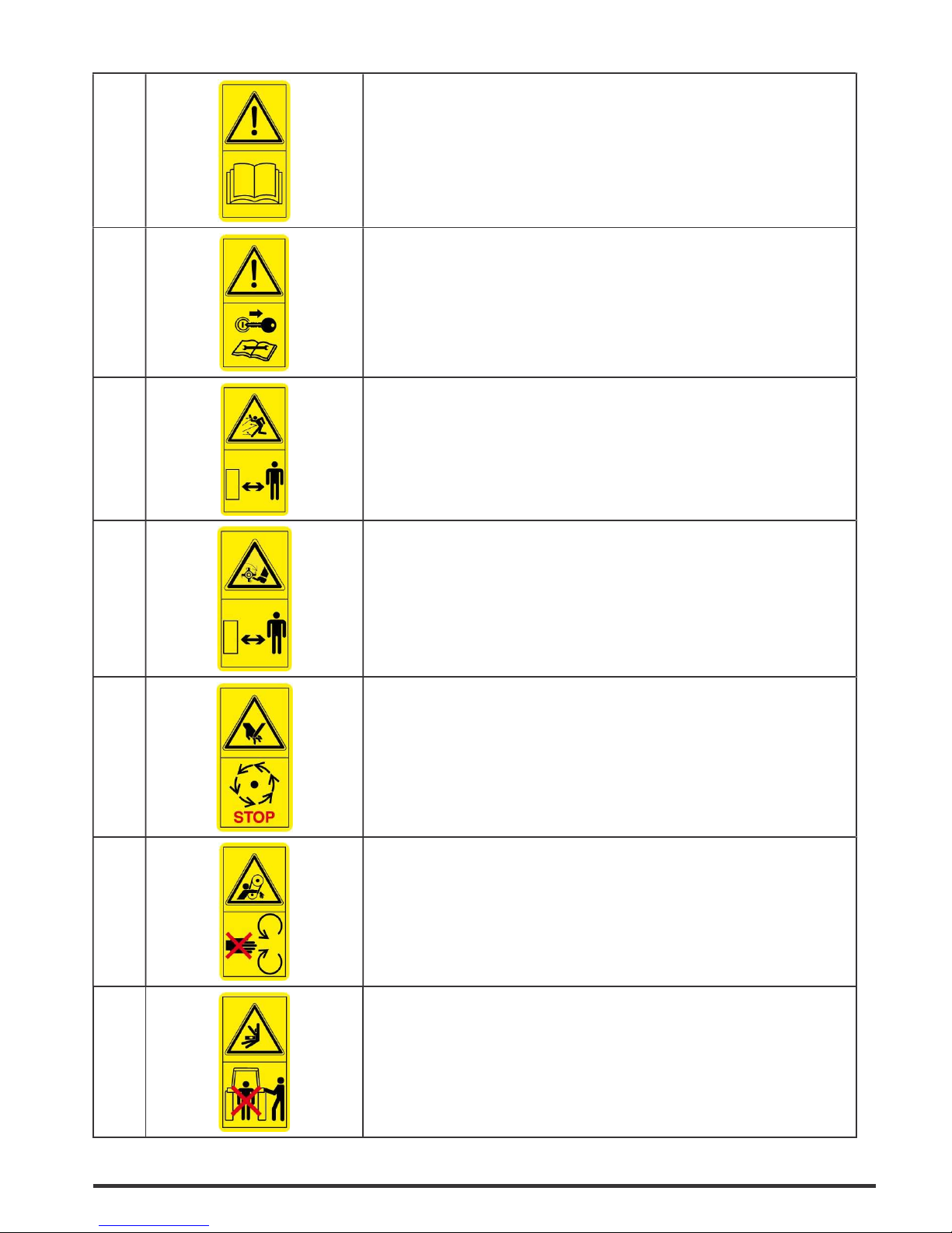
1
Carefully read the operator’s manuals of the
Flail Mulcher, tractor and cardan shaft before
using the machine
2
Disengage the PTO, turn off the tractor engine,
remove the key and ensure that all rotating parts have
stopped before approaching the implement.
Read the operator’s manual before performing any
maintenance operation.
3
Thrown or flying objects hazard.
Keep a safe distance from the machine.
4
Rotating knives: severing of lower limbs hazard.
Keep a safe distance from the machine.
5
Cutting of fingers or hand hazard. Wait
until all machine components have
completely stopped before touching them.
6
Rotating belts: fingers or hand entanglement hazard.
Do not open or remove safety shields
while engine is running.
7
Crushing hazard.
Stay clear of draft link lifting range while in operation.
Page 18

20
8
Implement input driveline: body entanglement hazard.
Do not open or remove safety shields
while engine is running.
9
Before engaging the tractor PTO, check that
rpm rate and sense of rotation are those
prescribed for the implement.
10
Lower limbs crushing hazard.
Keep a safe distance from the machine.
11
Crushing hazard.
Do not stand rear the machine.
12
Hydraulic lines under pressure: keep safe distance.
Before carrying out maintenance operations, ensure the line has
been depressurized and does not contain any hot
fluid.
13
Always wear protective clothing and equipment
appropriate for the job:
hearing protection, safety shoes, safety gloves,
safety glasses and overall.
Page 19
21
4. SET UP
The Flail Mulcher is delivered equipped with a driveshaft and related operating manual.
When the machine is delivered, check that there is no damage to the Flail Mulcher or driveshaft. In case of
damage or missing parts immediately notify the Manufacturer or your Dealer.
Because of his size, the machine could be delivered with some parts to be assembled.
In this case, the assembly of such parts is the dealer’s task, and must be performed carefully, with
reference to the tables of the Spare parts section.
WARNING
For proper tightening torques of bolts and screws, refer to the table in this manual.
4.1. CONNECTING TO THE TRACTOR
The Flail Mulcher is designed to be mounted on tractors equipped with 3-point Hitch Category I (ISO
730 standard).
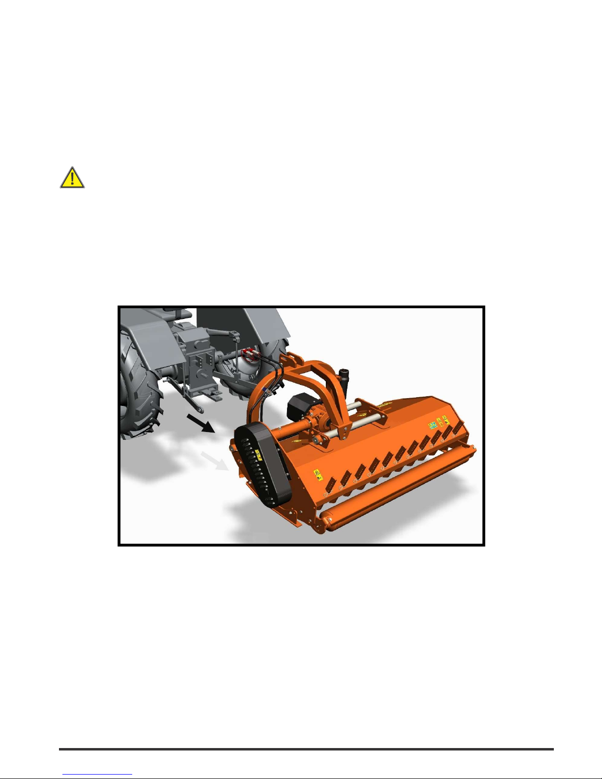
To connect the Flail Mulcher to the tractor the operator must do the following:
• drive the tractor in reverse, up to align the rear lifting arms to lower hitches of the Flail Mulcher in
parking
(see picture below);
• set the tractor’s parking brake, stop engine, remove the ignition key and get off the tractor;
• connect the lifting arms of the tractor to the lower hitches of the Flail Mulcher, and the 3-point top link to
the
upper hitch of the Flail Mulcher, through the use of the pins and the relative safety split pins;
• raise the Flail Mulcher until PTOs of tractor and machine are at the same height, then adjust the 3-point
top link so that the front of the machine is leveled to the back (the axis of the Flail Mulcher PTO must
be parallel to the ground), in order to limit stress transmitted to the Flail Mulcher through the cardan
shaft;
• make sure that left side of the Flail Mulcher is leveled with the right, by adjusting the tractor lifting arms,
then lock the arms to prevent swinging that could compromise the stability of tractor and machine
• finally adjust the parking stand, placing it at the highest point by means of the related linch pin.
Page 20

22
WARNING
Before connect the Flail Mulcher to the tractor, make sure that tractor and Flail Mulcher are on a flat, stable
and dry surface
4.2. DRIVELINE INSTALLATION
The gearbox unit is equipped with a free wheel inside, able to absorb the rotor inertia during stopping, and
to prevent possible damage to the transmission system machine-tractor that would be caused by an
instantaneous stop of the rotor.
Consequently, the use of a cardan shaft with free wheel is not required.
Before installing the driveshaft, the operator must read the manuals of driveshaft and tractor, checking in
particular that rpm and direction of rotation of the tractor PTO match those of the Flail Mulcher.
If the direction of rotation of the PTO tractor does not match that of the machine, contact the Manufacturer
or your Dealer.
To connect the driveshaft to the tractor and implement, the operator must:
park tractor and Flail Mulcher on a flat surface, with parking brake set, engine off, and ignition key
removed;
check that driveshaft, Flail Mulcher and tractor are in good condition, otherwise provide for their
replacement;
remove the PTO shield of the Flail Mulcher through the fixing screws;
insert the driveline yoke on the implement PTO by first lining up the splines, then ensure its tightening
onto the shaft through its fastener/snap pin;
replace the PTO shield of the Flail Mulcher through the fixing screws;
insert the driveshaft yoke on the tractor PTO, then ensure its tightening onto shaft through its fastener;
hook to the tractor and Flail Mulcher the two retaining chains of the driveline shielding, to prevent
shielding rotation during functioning of the machine.
DRIVELINE LENGTH CHECK
Before operating the Flail Mulcher, ensure that the size of driveshaft is adequate. The driveshaft
supplied with the machine has a standard length, therefore it may need an adaptation of the
length, depending of the tractor which the Flail Mulcher is combined.
The length of the driveshaft must be such to:
• avoid bottom out of the transmission tubes, when the driveshaft is in compressed position (when Flail
Mulcher is raised up off the ground);
• ensure an overlapping of the transmission tubes enough to transmit the torque required, when the
driveshaft is in max extension (when Flail Mulcher is in its lowest position in the ground).
When the driveshaft is at its minimum length (max compressed position), there must be at least a
2 cm of distance between the ends of each transmission tube and the yokes side.
When the driveshaft is at its maximum operational extension, there must be an overlap between
the tubes profiles of 15 cm at least.
Page 21

23
FLAIL MULCHER
– BPF Series
max. extended
position
15
cm
max.
compressed
position
2
cm
A driveshaft too long may cause structural damages to the tractor and machine. If the driveshaft is too
long, it may be adapted by removing it and shortening the tubes according to the instructions provided by
the Manufacturer in its use and maintenance manual.
A driveshaft too short can cause disengage of the tubes during operation, with severe hazard for the
operator and structural damage to the tractor and machine. If the driveshaft is too short, it must be replaced
with a longer one. In this case contact the Manufacturer or your Dealer.
IMPORTANT
• before operating the Flail Mulcher the first time, make sure that the driveshaft is lubricated in
accordance with how indicated in the instruction booklet;
• before operating the Flail Mulcher the first time, and after long periods of inactivity, make sure that the
driveline clutch has run a short “run in” in accordance with what indicated in the instruction manual of the
Manufacturer, removing the possible oxidation of the components that may compromise the correct
slipping during the usage (see also section “Maintenance”);
• always engage the tractor PTO at low rpm to minimize the effect of the peak torque on the driveline and
the machine.
Page 22

24
FLAIL MULCHER
– BPF Series
4.3. TRACTOR-IMPLEMENT STABILITY
The weight of the machine modifies the stability of the system tractor Flail Mulcher, resulting in loss of
steering
control and braking.
The front axle of the tractor should always loaded with at least 20% of the overall weight of the system
tractor Flail Mulcher.
CAUTION
Check the lifting capacity and stability of the tractor making sure the following relations are complied with
(see table below for definitions):
• M x (S1+S2) ≤ 0.2 x T x i + Z x (d+i)
• M ≤ 0.3T
If this not occurs, apply the front ballast required. To determine the appropriate characteristics of
the ballast, refer to the manual of the tractor.
i = Tractor wheelbase (cm)
d = Distance between front axle and ballast center of mass (cm)
T = Weight of tractor + operator (75 kg)
Z = Ballast weight (kg)
M = Implement weight (kg)
s1 = Distance between rear axle and lower hitch points (cm)
s2 = Distance between lower hitch points and implement center of mass = 61 cm
Page 23

25
FLAIL MULCHER
– BPF Series
5. OPERATING
Before operate the Flail Mulcher, make sure you have read and understood the operating manuals of the
Flail Mulcher, tractor and PTO shaft, and followed what is described in the section “Set Up”.
DANGER
During operation, adjustment, maintenance, repairing or transportation of the machine, the operator must
always use appropriate Personal Protective Equipment (PPE).
Before starting work, ensure that all machine guards are in good conditions and fully functional.
During operation, the machine can throw material from the back: prevent people and animals to approach
the operational area.
5.1. START-UP
WARNING
Before conducting the above inspections and service, make sure the tractor engine is off, all rotation parts
are completely stopped and the tractor is in park with the parking brake engaged. Make sure the machine
is resting on the ground or securely blocked up and the tractor lifting hydraulics locked.
Before the start up and before each use, perform the following pre-operation inspections and service of the
implement:
• check that the machine has all mechanical parts are in good condi
tion. Repair/replace damaged parts;
• check that the machine has no missing parts (pins, safety pins, plugs oil ...). Restore the missing parts;
• check that all guards and safety devices have no damages and are properly positioned. Repair and / or
replace the damaged shielding’s, restore the correct position;
• verify that the PTO driveshaft is properly installed (see section: Connection of the drive shaft);
• check that the driveshaft clutch is in good condition and is well greased (see Maintenance / Driveline);
• lubricate all greasing points of the machines (see Maintenance/Driveline and Maintenance/Support rotor);
• check for oil leaks from the gearbox or the transmission side cover. Identify the reason of loss, then
repair and / or replace the damaged components;
• check the correct oil level in the gearbox and in transmission side box (see section maintenance);
• check that the drive belts are in good condition.
• check that blades are not excessively worn and the relating hardware is correctly tightened (see section
Maintenance);
• check that all the machine hardware is properly tightened. Refer to the tightening table in the manual
for proper torque values;
• check that all safety decals are correctly positioned and in good condition. Replace any damaged decals;
• check that there are no constraints that may prevent the movement of equipment.
Before the start up and before each use, make the following checks on the operating area identified for
shredding:
• check that area is clear of foreign objects (rocks, branches or debris). Remove any obstacle and visibly
highlight obstacles that cannot be eliminated (e.g. by means flags);
• make sure in the working area exposed there are no people or animals;
• make sure the soil to be worked is not too grassy, muddy, sandy or rocky.
Once all the checks above have been done, start the tractor and the Flail Mulcher as follows:
• start the tractor and engage the PTO at low rpm, making sure that the Flail Mulcher is NOT in the raised
position but close to the ground, then increase the speed engine until to 540 rpm;
• lower the machine on the ground and simultaneously start driving the tractor at low speed.
Subsequently increase the ground speed depending on ground conditions;
• if the environmental temperature is extremely cold, it’s recommended to wait a few minutes with the
PTO of the tractor at low rate before lowering the Flail Mulcher completely on the ground;
Page 24

26
FLAIL MULCHER
– BPF Series
• drive for a while operating the Flail Mulcher, then stop the tractor to check the quality of the work
performed. If you need to get off the tractor, lift the Flail Mulcher just out of the ground, reduce
engine speed and disengage PTO, set the parking brake, stop engine and remove the ignition key.
If the cutting height and/or the quality of the shredding are not as desired, correct them by adjusting the
roller or the wheels (see sections “Adjustments”).
5.2. OPERATING INSTRUCTIONS
During operations:
• always keep the tractor engine at rpm rate ensuring to the Flail Mulcher the right power required for the
use;
• always keep a tractor speed adequate to working conditions (from 2 to 10 km/h approx.). Reduce speed
in the case of hard or stony soils;
• choose a driving pattern that provides the maximum pass length and minimizes turning;
• when working in the hills, if you can do “climbing” in the sense of the slope, in any case do not work
along the hillsides, making the steps from top to bottom to reduce the terrace. Where possible always
try to «work up» the slope. If this is not possible, avoid working along the contours of the hill and
operate up and down the slope to avoid a terracing effect;
• always perform changes and reverse of direction with PTO disengaged and the Flail Mulcher slightly lifted
from the ground to avoid damage to the machine;
• periodically check for foreign objects wrapped around the rotor shaft and remove them, after disenga-
ging PTO, turning off tractor engine, and removing ignition key;
• if the rotor strikes a foreign object, stop operating immediately, idle the engine speed and disengage
the PTO. Wait for stopping of all rotating parts, then raise the implement and proceed to check and
remove the object, after stopped the tractor, set the parking brake, stopped engine and removed the
ignition key. Repair any damages immediately, and make sure rotor is in good condition before restarting operation;
• avoid overheating of the gearbox due to materials extremely difficult to shred, in order to avoid dama-
ges of the gearbox.
Typical problems that may occur operating the Flail Mulcher are described into Troubleshooting section,
together with their solutions.
5.3. ADJUSTMENTS
WARNING
All adjustment operations must be performed with the tractor engine off, the PTO disengaged, the Flail
Mulcher lowered to the ground or on security stands, the parking brake set and the ignition key off.
CUTTING HEIGHT ADJUSTMENT
The cutting height of the Flail Mulcher is determined by the vertical position of the rear on the machine.
Lifting up the roller the tools of the rotor get closer to the ground, reducing the cutting height. On the
contrary, lowering the roller the tools increase their distance from the ground, increasing the cutting
height.
After a change of the working height, make sure that the tools of the rotor are not interfering with the soil:
a direct contact with the ground would facilitate the rapid wearing of the tools.
Page 25

27
FLAIL MULCHER
– BPF Series
If the Flail Mulcher is provided with a stabilizer roller, to adjust the cutting height:
lift the Flail Mulcher, put it on safety stands, then turn off the tractor engine, disengage the PTO, set
the
parking brake and remove the key from the panel;
remove the bolts (1) that secure the roller supports to the frame on both sides;
position the roller according to the height required;
Replace and tighten the bolts (for the correct torque value refer to the torque table of the manual).
Depending on the different roller positions, it is possible to set four different cutting heights: 32-57-82 and
107 mm.
When finished, make sure that the roller supports are positioned at the same height, and check, with
the Flail Mulcher resting on the ground, that the front of the machine is leveled with the back. If
necessary, adjust the level through the 3-point top link of the tractor.
1
Page 26

28
FLAIL MULCHER
– BPF Series
SKID ADJUSTMENT
The position of the skids can be adjusted by:
loosening and removing the bolts (1) that clamp the skids to the side plates of the frame,
reposition the skids according to the needs, and
retightening the bolts (1).
The skids can be placed in 3 different positions but, in the presence of the stabilizer roller or the pivoting
wheels, they have the unique function of protecting the side plates of the frame from any direct contact with
the ground.
Therefore, make sure the skids are not positioned below the roller or wheels, because the latter two a
the devices holding the Flail Mulcher l i fted of the ground (and not the skids).
RAKE ADJUSTMENT
The function of the rear rakes is to obtain a finer mulch by holding the material within the material in
the shredding chamber.
It is therefore recommended to perform the racks adjustment immediately after executing the cutting
height adjustment.
To do this follow these steps:
• remove the cotter pin (1) from one of the rakes;
• push the rake downwards in order to retain more material inside the shredding chamber and obtain
a finer mulch. Vice-versa, pull the rake upwards to retain less material inside the shredding chamber
and to obtain a coarse mulch;
• insert the split pins (1) on the hole of the rake closest to rear bar, after setting the desired position;
• repeat the procedures adjusting all other rakes to the same height of the first one.
1
2
1
Page 27
29
FLAIL MULCHER
– BPF Series
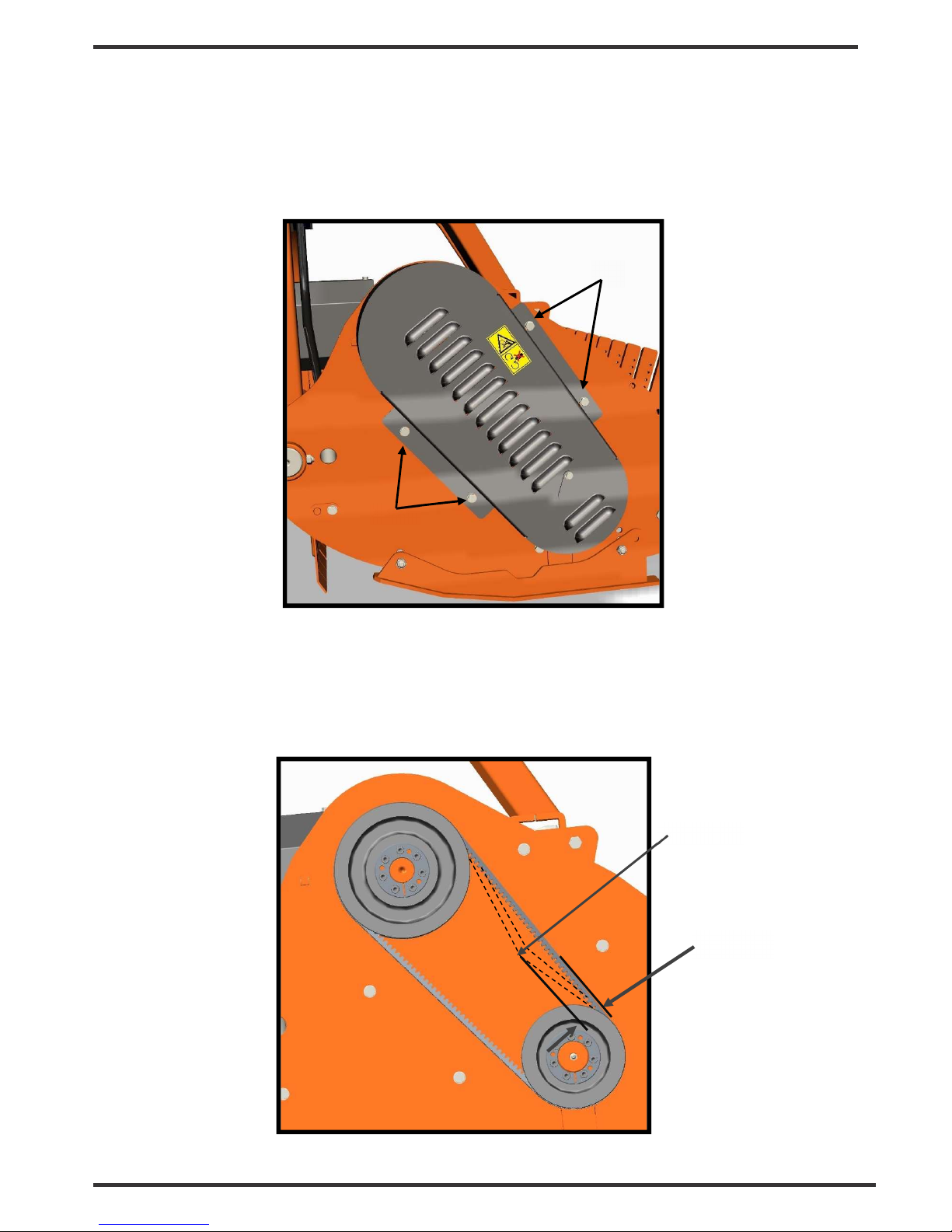
BELT ADJUSTMENT
To check the correct belt tensioning of the side transmission,
remove the safety cover of the belts by loosening
the four bolts (1) that secure it to the frame (see
picture):
Check the correct belt tension.
Apply a force of about 10-15 kg on the middle of the belts set, and measure the entity of the consequent
deflection of the belts (see picture):
1
1
10 MM
10 Kg
Page 28

30
FLAIL MULCHER
– BPF Series
If the deflection is about 10 mm, the tension is correct.
If is not so, proceed with the adjustment in the following way (see picture below):
• loosen the four nuts (1) under the gearbox which lock it to the frame;
• loosen the two bolts (2) fixing the extension tube to the side plate of the frame;
• while holding the screw (3), loosen the lock nuts (4);
• tighten the tension nut (5) if the tensioning found is too low (deflection of belts higher than 10 mm);
unscrew the tension nut (5) if the tensioning found is too high (deflection of belts lower than 10 mm).
• retighten the lock nuts (4) and the two bolts (2) fixing the extension tube to the side plate of the frame;
• move the gearbox in order to restore the position of the extension tube perpendicular to the side plate
of the Flail Mulcher;
• retighten the four nuts (1) under the gearbox;
• reposition the safety cover in his original place.
1
2
4
3
5
Page 29

31
FLAIL MULCHER
– BPF Series
If the replacement of the set of belts is required:
• remove the safety cover of the belts by loosening the four bolts that secure it to the frame
• loosen the four nuts (1) under the gearbox which lock it to the frame;
• loosen the two bolts (2) fixing the extension tube to the side plate of the frame;
• loosen the lock nuts (4) and the tension nut (5) until the extraction of the belts from their seats on the
pulleys is permitted, starting from the external position (a)
• reinsert the new belts in succession contrary to what done for the disassembly.
• adjust the belt tension according to the indications done above
• retighten the two bolts (2) fixing the extension tube to the side plate of the frame;
• move the gearbox in order to restore the position of the extension tube perpendicular to the side plate
of the Flail Mulcher;
• retighten the four nuts (1) under the gearbox;
• reposition the safety cover in his original place.
a
Page 30

32
FLAIL MULCHER
– BPF Series
5.4. STOPPING AND DISCONNECTION
To stop the Flail Mulcher at the end of a working session:
• bring the tractor to a complete stop;
• place the transmission in park or neutral;
• reduce the engine speed, then disengage the PTO;
• wait for stopping of all rotating parts;
• lower the implement to the ground;
• set the parking brake;
• shut down the engine and remove the key before exiting the tractor;
• do the cleaning and maintenance required to make the machine ready for later use (see section
Maintenance).
WARNING
Never leave the tractor unattended with the implement in the lifted position.
To disconnect the Flail Mulcher from the tractor (e.g. to make a change of implement):
• adjust the parking stand to the lowest position, through the use of relative retaining pin;
• park the tractor on a dry and level surface;
• reduce the engine speed, then disengage PTO;
• wait for stopping of all rotating parts;
• lower the implement to the ground;
• set the parking brake;
• shut down the engine and remove the key before exiting the tractor;
• place safety blocks under Flail Mulcher to prevent unit from tipping over onto a child and/or an adult. A
Flail Mulcher that tips over can result in injury or death;
• disconnect the driveline from the tractor PTO and rest it on the provided support of the Flail Mulcher;
• disconnect the top link and rear lifting arms of the tractor from the Flail Mulcher hitches;
• check the Flail Mulcher stability. If needed, place additional safety blocks;
• get on the tractor, start the engine and move away from the Flail Mulcher slowly;
• make sure the Flail Mulcher remains stored in a protected area, to prevent that unauthorized
personnel can approach it.
Before a long term storage (e.g. at seasonal end), do cleaning and maintenance operations as specified in
sections MAINTENANCE and STORAGE.
5.5. TRANSPORTING
To set the Flail Mulcher for transportation, perform the following steps:
• idle tractor engine, disengage tractor PTO, and wait for stopping of all rotating parts;
• lift the Flail Mulcher until the transport position, making sure the driveline transmission tubes does
not contact tractor or Flail Mulcher. A minimum gap of 2 cm should be leaved between the tubes
and tractor and Flail Mulcher (see also section Driveline installation);
• lock the tractor lifting hydraulics, turn off the engine, set the parking brake, remove ignition key and
get off the tractor;
• adjust the parking stand to the highest position, through the use of relative retaining pin, to prevent its
possible damage during transport.
When driving on public roads, follow strictly all local laws and traffic regulations.
Page 31

FLAIL MULCHER
- BPF Series
33
WARNING
When driving on public roads, reduce your speed, be aware of traffic around you and proceed in
such a way that faster moving vehicles may pass you safely.
6. MAINTENANCE
Proper and regular maintenance ensures a long life of the equipment, avoids failures and saves
time and repair costs.
Periodic inspections and maintenance operations described in this section must be performed by
operator in the times and terms prescribed. Failure to comply with maintenance prescriptions can
compromise the functioning and duration of the machine, and consequently invalidate the
warranty.
The frequency of maintenance indicated refers to normal conditions of use: it must be intensified in
severe operating conditions (frequent stops and starts, prolonged winter season etc ...).
Repairs, maintenance and modifications other than those mentioned in this paragraph should NOT
be performed without consulting the Manufacturer or your Dealer. Manufacturer, as the case, may
give the authorization to proceed with the repair together with all necessary instructions.
Wrong or inappropriate repairs or maintenance may generate abnormal operating conditions,
equipment damage and generate risks for the operator.
WARNING
For safety reasons, all maintenance operations must be performed with tractor PTO disengaged,
Flail Mulcher stopped and completely lowered to the ground or onto support blocks, parking
brake set, tractor engine shut off, and ignition key removed.
IMPORTANT
Respect the environment. Store or dispose of unused chemicals as specified by the chemical
Manufacturer.
6.1. ROTOR TOOLS REPLACEMENT
Frequently check the wear condition of the tools on the rotor (Y blades or hammers) through visual
inspection. The wear of the tools is very variable depending on the type of soil.
Replacement of the tools is necessary when the operator notices increase of power absorption during
operations, or when the blades or hammers dimension is significantly reduced compared to the original.
The use of the machine with tools in bad condition compromises the quality of the work.
Before perform replacement of the blades:
• idle tractor engine, set the parking brake, disengage tractor PTO, and wait for all moving parts to come to
a complete stop;
• place the machine slightly lifted from the ground on safety blocks or mechanical stands;
• lock the control lever of the hydraulic lift of the tractor;
• turn off the tractor and remove the key from the control panel.
To perform the replacement of blades:
• remove the bolt that locks the couple of Y blades (or the hammer) in the rotor. For the Y blades, two
bushing are placed on the bolt to fill the gap between the blades and the holders of the rotor;
• place the new tool instead of the one worn out, and tighten the bolts with washers, referring to the
torque values shown in “Table torques” in the manual. Be sure to install the cutting edge facing in the
direction of rotation of the rotor.
For the rotor with Y blades do not forget to place the related
bushings between the blades and the holders.
• repeat the same procedure for all the Y blades (or hammers);
• repeat this process for all the tools.
Page 32

FLAIL MULCHER
- BPF Series
34
IMPORTANT
Remove and install one blade/hammer at a time to ensure blades/hammers are correctly oriented when
installed.
Replace worn blades only with original parts.
WARNING
When the blades/hammers are worn out it is necessary to replace the full set of tools.
Replacement of only some of the tools is certainly cause of the rotor unbalance, machine vibrations and
can compromise the reliability of the Flail Mulcher and generate risks to the operator.
CAUTION
Worn blades and hammers may be very sharp!
6.2. GEARBOX LUBRICATION
Lubricant: AGIP ROTRA MP SAE 85W/140 oil gear or equivalent
CAUTION
Before touching the gearbox wait until it has cooled sufficiently.
Check the oil level every 50 hours, making sure the level is aligned with the level plug (1).
To perform the check, it is necessary to remove the screws (2) holding the safety cover on the gearbox,
which prevents access to the plug.
If the oil level is below the line of the level plug, it’s necessary fill up oil till restore the correct level.
The oil change must be performed:
• after the first 50 working hours;
• each 500 working hours.
To make the oil change:
• unscrew the level plug (1);
• place a tank under the oil drain plugs (3);
• unscrew the oil drain plugs (3) and drain oil completely into the tank;
• retighten the drain plug (3);
• unscrew the oil filling plug (4) on the top of gearbox;
• fill up oil till the level reach the hole of the level plug (1);
• retighten level plug (1) and the filling plug (4);
• replace the safety cover retightening the screws (2);
• dispose the discharged oil into containers for used oil.
4
1
3
4
Page 33

FLAIL MULCHER
- BPF Series
35
IMPORTANT
Frequently check possible oil leaks from the Flail Mulcher through visual inspection, and in case of
leakage provide immediately proper maintenance.
Avoid oil leaks on the ground when restoring oil level or making oil change.
6.3. ROTOR BEARINGS LUBRICATION
Lubricant: AGIP GREASE MU EP 2 lithium-type grease (or equivalent)
Frequency: each 20 working hours
Lubricate with multipurpose lithium-type grease through a manual grease pump, after meticulous cleaning of
grease nipples.
To perform lubrication (see pictures):
• turn the cover (1) and inject grease through the nipple (2);
• inject grease through the nipple (3).
IMPORTANT
Make sure to clean the fitting Grease nipple before using the grease gun.
Do not let excess grease collect on or around parts, particularly when operating in sandy areas.
2
3
1
Page 34

FLAIL MULCHER
- BPF Series
36
6.4. ROLLER BEARINGS LUBRICATION
Lubricant: AGIP GREASE MU EP 2 lithium-type grease (or equivalent)
Frequency: each 20 working hours
To perform lubrication, inject grease into the nipples (1) and (2), located on the upper part of the roller
bearing supports (see pictures).
6.5. DRIVE BELTS REPLACEMENT
Frequently check the wear of the belts, and if one or more of these appears worn replace the full set.
To replace the drive belts, refer to the section “Belts tensioning adjustment”.
6.6. DRIVESHAFT MAINTENANCE
Lubricant: AGIP GREASE MU EP 2 lithium-type grease (or equivalent)
Frequency: each 20 working hours
Grease crosses, sliding parts of protective shielding and driveshaft transmission tubes.
IMPORTANT
For details about maintenance and lubrication of the driveshaft, refer to the user manual of the driveshaft
Manufacturer.
NOTE
For the driveshaft service parts, refer to the user manual of the driveshaft Manufacturer.
2
1
Page 35

FLAIL MULCHER
- BPF Series
37
7. STORAGE
Before leaving the machine unused for a long time, it’s necessary to perform following tasks to preserve
the appearance and functionality of the machine, and to make easier the restart at later use:
• park the Flail Mulcher on a flat surface, in a place dry and protected from exposition to the elements,
possibly with storage temperature between 0 and 50 °C (see section Stopping and disconnection);
• thoroughly clean the machine, removing from the rotor all residues due to tillage, in order to avoid
damage from grass and stagnant water;
• inspect carefully the machine, checking for worn and/or damaged parts. Perform immediately all repairs
and/or replacements needed, in order to make the machine ready for restarting;
• in case of abrasion of painted surfaces, provide restoring the surface protection through touchup paint
to prevent rust;
• make sure the safety decals are in their original positions, intact and legible. When required, replace
the decals immediately;
• lubricate properly all grease points, and restore the oil levels as indicated in the Maintenance section.
Use protective oil to coat the exposed mechanical components and to protect them against rust.
8. SCRAPPING
In case of scrapping, the machine must be disposed in appropriate and authorized sites, according to local
legislation.
Before scrapping, separate plastic parts from rubber parts, aluminum, steel, etc.
Recover and dispose any exhausted oils to authorized centers for oil collecting.
Page 36

FLAIL MULCHER
- BPF Series
38
9. TROUBLESHOOTING
PROBLEM POSSIBLE CAUSE POSSIBLE SOLUTION
Oil leaking from gearbox/
transmission case
• Gearbox overfilled
• Loose filling/drain/level plug
• Damaged breather plug
• Damaged seals
• Drain to proper level
• Replace breather plug
• Tighten filling/drain/level plug
• Replace seals
Shredding not uniform
• Worn blades/hammers
• Roller/wheels set in wrong way
• Debris wrapped on rotor
• Dirty shredding room
• Replace blades/hammers
• Set the roller/wheels correctly
• Reduce the ground speed
• Clean the shredding room
Gearbox overheating
• Low oil level
• Material difficult to be shredded
• Add oil
• Reduce the ground speed
Blades/hammers wear
frequently
• Hard soil
• Cutting height too low
• Check the soil in advance
• Increase the cutting height
Flail Mulcher noise and
vibration noticeable and
constant
• Unbalanced roller
• Worn bearings
• Blades/hammers worn,
damaged or missing
• Balance the roller in authorized
shop
• Replace bearings
• Replace blades/hammers
10. TORQUE VALUES TABLE
Check frequently Flail Mulcher hardware to make sure that screws and bolts are tightened
according to torque values listed in following table:
8.8 GRADE 10.9 GRADE
BOLT SIZE
(METRIC)
Nm
Nm
M6 11 15
M8 26 36
M10 52 72
M12 91 125
M14 145 200
M16 225 315
M18 310 405
M20 440 610
Page 37

FLAIL MULCHER
- BPF Series
39
11. WARRANTY
Tirth Agro Technology Pvt. Ltd. offer the following warranty to the purchaser of COSMO BULLY ROTARY
HOE mentioned herein above subject to the conditions set out herein after provided the COSMO BULLY
ROTARY HOE shall be in the possession of and used by such purchaser as from the date of delivery.
Tirth Agro Technology Pvt. Ltd. warrants its products for a period of twelve (12) months against
defective parts. This warranty shall not apply to implements or parts that have been subjected to
negligence, of accident, or that have been altered or repaired or used with non-genuine parts.
CONDITIONS
If you wish to make a warranty claim you must first contact the supplier of your goods to
begin the claim process.
The following are the warranty terms and conditions for new goods sold in Australia by Farm
Implements P/L in conjunction with the manufacture Tirth Agro Technology Pvt. Ltd ( “We”, “Our” or
“Us”), both of 16 Cahill Street, Dandenong, Victoria, Australia, 3175.
1. To the extent that any goods or services supplied by Us are supplied to a ‘consumer’ as defined in
the Australian Consumer Law, We will comply with any applicable consumer guarantees and the
following statement will apply: “Our goods come with guarantees that cannot be excluded under
the Australian Consumer Law. You are entitled to a replacement or refund for a major failure and
for compensation for any other reasonably foreseeable loss or damage. You are also entitled to
have the goods repaired or replaced if the goods fail to be of acceptable quality and the failure
does not amount to a major failure.”
2. ‘Australian Consumer Law’ means Schedule 2 of the Competition and Consumer Act 2010 (Cth).
3. The warranties provided in this document are in addition to any other rights or remedies available
to you under the law, and do not limit the consumer guarantees for ‘consumers’ under the
Australian Consumer Law.
4.
Goods presented for repair may be replaced by refurbished goods of the same type rather than
being repaired. Refurbished parts may be used to repair the goods.
5. Any warranty claim that is the result of operator abuse, neglect or unauthorised modifications
being made to the good will not be considered valid, subject to the Australian Consumer Laws.
The warranty does not cover costs of claiming under this warranty; depreciation, damage,
malfunction or failure caused by normal wear and tear; lack of reasonable maintenance or
improper servicing; failure to follow operating instructions; misuse or lack of proper protection
during storage. The expected normal working conditions and maintenance requirements are
outlined in the relevant operator’s manual.
6. All new Implements are provided with a 12 month comprehensive warranty from the date of
invoice against faulty workmanship or materials, under normal working conditions and service, as
outlined in the relevant operational manual for the particular good. Your warranty for those goods
will be considered void if any damage to the implement is caused by operator abuse, neglect, or if
any unauthorised modifications have been made.
7. If you wish to make a warranty claim, you must immediately report the defect to the supplier
within the warranty or consumer guarantee claim period, including a written statement of your
claim, along with photos of the current condition of the goods by mail (or if possible, email) to the
address of the place from which you purchased the good. You will be required to present valid
proof of purchase, and at your expense promptly provide the goods to the supplier immediately
after notification of a service issue.
Page 38

FLAIL MULCHER
- BPF Series
40
8. Please note that We require an assessment of the condition of the goods to be conducted by
either the supplier, Us or the manufacturer, as well as obtaining a history of use of the good,
before We can determine whether a consumer guarantee or manufacturer’s warranty is applicable.
We are not responsible for any transportation cost incurred in the repair or replacement of parts
not covered by the warranty.
9. To the maximum extent permitted by law, and except in circumstances where the consumer
guarantee provisions under the Australian Consumer Law apply and are inconsistent with the
following, Our liability for the supply of the goods is limited, at Our discretion, to 1) replacement
of the goods or the supply of equivalent goods; 2) repair of the goods; 3) payment of the cost of
replacing the goods or acquiring equivalent goods; or 4) payment of the cost of having the goods
repaired.
10. You acknowledge that use of the goods is inherently dangerous and agree that to the
maximum extent permitted by law, We are not liable in any event for consequential loss, damage
or injury, including loss of crops, loss of profits, or personal injury or death howsoever caused.
11. Farm Implements Dealers have no authority to make any representation, promise or
admission on behalf of Us or to modify the terms or limitations of these Warranty Conditions in
any way. Nothing in these Warranty Conditions constitutes a partnership between Us and any
Farm Implements Dealer, or constitutes any Authorised Dealer as an agent or employee of Ours
for any purpose at all. Our Dealers have no authority or power to bind Us, to contract in the
name of Farm Implements P/L or to create a liability against Us in any way or for any purpose at
all, including but not limited to representations regarding performance or fitness for any purpose
of the goods.
If you have specific queries regarding the warranties or consumer guarantees provided by
Farm Implements P/L in conjunction with the manufacture Tirth Agro Technology Pvt. Ltd
please send details of your claim to Our attention at 16 Cahill Street, Dandenong, Victoria,
Australia, 3175, or via email at sales@farmimplements.com.au or phone 03-9706-5166.
THIS CONTRACT WILL BE INEFFECTIVE AND INOPERATIVE IF:
a. The COSMO BULLY ROTARY HOE has not been delivered, assembled, started and put into
operation by the company or its Authorized Representative.
b. The warranty card has not been returned within 30 days of date of purchase.
c. The COSMO BULLY ROTARY HOE parts thereof is subjected to neglect, fire, flood or other acts
of God or if in the company’s opinion any damage has caused to the COSMO BULLY ROTARY
HOE in transportation.
d. The original numbers are removed, obliterated or altered from the unit.
e. Any attempt is made to have the repairs executed by a person or persons, other than the
company or its authorized representative.
f. Any defect is not informed immediately to the company or its authorized representative, any
alteration in warranty card is made.
g. Any change in the location of the COSMO BULLY ROTARY HOE or in its ownership during the
warranty period must be intimated in writing to the company or its Authorized Representative
ten days before the change. Failure to do so will absolve the company from the obligation under
this warranty.
h. Damage to the COSMO BULLY ROTARY HOE or any part thereof caused, during shifting or
transportation is not covered by this warranty.
Page 39

FLAIL MULCHER
- BPF Series
41
i. This warranty is given in lieu of all other guarantees and condition expressed or implied by law
or by any person purporting to act on behalf of the COMPANY and excludes every condition,
warranty or guarantee not herein expressly set out.
NT – Parts/materials that are not covered by the warranty are as follows:
1. Blade
2. Universal Joint Cross
3. Paint
4. Bearing
5. Rubber Parts
6. Gaskets
7. Fasteners
WHEN THE WARRANTY BECOMES VOID
Besides the cases specified in the supply agreement, the warranty shall in any case become
void:
Should there have been a maneuvering error, use of an inadequate safety bolt on the cardan
shaft torque limiter or when the cardan shaft clutch has been damaged through improper
maintenance.
When the implement has been used beyond the specified power limit as given in the technical
data chart.
When following repairs made by the customer without authorization from the manufacturer or
owing to instillation of spurious spare parts, the machine is subjected to variations and the
damage can be ascribed to these variations.
Whenever the user or anyone else on his behalf applies equipment to the machine that has not
been expressly approved by the manufacturer.
When the user failed to comply with the instructions in this manual book.
Page 40

FLAIL MULCHER
- BPF Series
42
12. SPARE PARTS
All repairs and replacements on the machine must be performed only by using original spare parts, which
must be obtained from the Manufacturer or your Dealer.
This section contains the information needed to identify the parts of BPF Flail Mulcher that may be ordered
to
Manufacturer.
When request spare parts to Manufacturer, always give following indications:
• type of machine;
• Flail Mulcher serial number;
• description and p/number of the spare parts;
• quantities.
NOTE
For identification of p/numbers and description of safety decals refer to the Section Safety labels.
For identification of p/numbers and description of PTO driveline parts, refer to the manual of the
driveshaft Manufacturer.
The Manufacturer reserves the right to substitute a required part with an equivalent part, if
applicable.
Page 41

FLAIL MULCHER
- BPF Series
43
Page 42

FLAIL MULCHER
- BPF Series
44
Top mast assembly
Sr No. Part no Description Qty.
1 17589 TOP MAST ASSEMBLY (BPF) 1
2 17590 TOP MAST COMP (BPF) 1
3 17442 SIDE STAND PIPE COMP (BMF) 1
4 14267 SQ. SNAPPER PIN D10 X L70 1
5 17444 BRACKET PIN (CAT. І-П) (BMF) 2
6 17445 TOP MAST PIN (CAT. І-П) (BMF) 1
7 23068 R-CLIP D5 X L100 MM 3
8 17591 GUIDE BAR BUSHING Ø74.5XØ60.3X10⁷ (BPF) 2
9 17284 OIL SEAL 75 X 60 X 8 2
10 25216 CIRCLIP INTERNAL M75 X 2.5 2
11 17592 GUIDE BAR ROLLER (BPF) 2
12 17593 HEX BOLT M14 X 2 X 115 (HT) (8.8) DIN931 2
13 1574 NYLOCK NUT M14X2.00 (DIN-982) 2
14 14266 SQ. PIPE PLASTIC CAP 32MM 1
15 26030 MANUAL BOX COVER 1/2(SMMSD) 1
16 8064 PLAIN WASHER 8mm 3
17 8190 HEX BOLT M8 X 1.25 X 15 3
Page 43

FLAIL MULCHER
- BPF Series
45
Page 44

FLAIL MULCHER
- BPF Series
46
Leveler assembly
Sr No. Part no Description Qty.
1
17491 LEVELLER ASSEMBLY (BMF-160)
1
17492 LEVELLER ASSEMBLY (BMF-180)
17594 LEVELLER ASSEMBLY (BPF-200)
17595 LEVELLER ASSEMBLY (BPF-225)
2
17478 LEVELLER PIPE COMP (BMF-160)
1
17479 LEVELLER PIPE COMP (BMF-180)
17596 LEVELLER PIPE COMP (BPF-200)
17597 LEVELLER PIPE COMP (BPF-225)
3 17481 LEVELLER ADJUSTMENT PLATE LH COMP (BMF) 1
4 17480 LEVELLER ADJUSTMENT PLATE RH COMP (BMF) 1
5 17482 LEVELLER DUST COVER PLATE (BMF) 2
6
17485 SCRAPPER (BMF-160)
1
17486 SCRAPPER (BMF-180)
17598 SCRAPPER (BPF-200)
17599 SCRAPPER (BPF-225)
7 17285 BEARING 1306 2
8 1002 CIRCLIP INTERNAL 72mm 2
9 1001 OIL SEAL 35 X 72 X 10 2
10 17487 WASHER Ø44 X Ø10.5 X 4 (BMF) 2
11 17276 HEX BOLT M10 X 1.50 X 20(FT)(8.8) DIN933 2
12 20148 GREASE NIPPLE M8 X 1.25 2
13 17286 CSK BOLT M6 X 1 X 12 6
14 8126 PLAIN WASHER 12mm 4
15 17488 HEX BOLT M12 X 1.75 X 40(HT)(8.8) DIN933 2
16 1209 M12X1.75 NYLOCK NUT 2
Page 45

FLAIL MULCHER
- BPF Series
47
Page 46

FLAIL MULCHER
- BPF Series
48
Rotor assembly
Sr No. Part no Description Qty.
1
17686 ROTOR ASSY WITH HOUSING (BPF-160)
1
17602 ROTOR ASSY WITH HOUSING (BPF-180)
17603 ROTOR ASSY WITH HOUSING (BPF-200)
17604 ROTOR ASSY WITH HOUSING (BPF-225)
2
17687 ROTOR ASSY WITH HAMMER BLADE (BPF-160)
1
17605 ROTOR ASSY WITH HAMMER BLADE (BPF-180)
17606 ROTOR ASSY WITH HAMMER BLADE (BPF-200)
17607 ROTOR ASSY WITH HAMMER BLADE (BPF-225)
3
17688 ROTOR COMP WITH EXTENTION (BPF-160)
1
17608 ROTOR COMP WITH EXTENTION (BPF-180)
17609 ROTOR COMP WITH EXTENTION (BPF-200)
17610 ROTOR COMP WITH EXTENTION (BPF-225)
4 17521
HEX BOLT M20 X 2.5 X 100 (10.9) (SBPF 1.60)
16
HEX BOLT M20 X 2.5 X 100 (10.9) (SBPF 1.80)
HEX BOLT M20 X 2.5 X 100 (10.9) (SBPF 2.00)
20
HEX BOLT M20 X 2.5 X 100 (10.9) (SBPF 2.25)
5 17067
HAMMER BLADE (137X40) (SRM) (SBPF 1.60)
16
HAMMER BLADE (137X40) (SRM) (SBPF 1.80)
HAMMER BLADE (137X40) (SRM) (SBPF 2.00)
20
HAMMER BLADE (137X40) (SRM) (SBPF 2.25)
6 25548
SPRING WASHER M20 (SBPF 1.60)
16
SPRING WASHER M20 (SBPF 1.80)
SPRING WASHER M20 (SBPF 2.00)
20
SPRING WASHER M20 (SBPF 2.25)
7 9017
NYLOCK NUT M20X2.50 (DIN-982) (SBPF 1.60)
16
NYLOCK NUT M20X2.50 (DIN-982) (SBPF 1.80)
NYLOCK NUT M20X2.50 (DIN-982) (SBPF 2.00)
20
NYLOCK NUT M20X2.50 (DIN-982) (SBPF 2.25)
8 17287 BEARING 22210 2
9 17611 ROTOR SHAFT HOUSING (BPF) 2
10 14122 OIL SEAL 55 x 90 x 10 2
11 17288 OIL SEAL 50 X 68 X 8 2
12 3027 INTERNAL CIRCLIP 90MM 2
13 25099 CIRCLIP EXTERNAL 50 MM 1
14 20272 GREASE NIPPLE M10 X 1.50(STRAIGHT) 1
15
17740 ROTOR ASSY W/O HAMMER BLADE (BPF-160)
1
17741 ROTOR ASSY W/O HAMMER BLADE (BPF-180)
17742 ROTOR ASSY W/O HAMMER BLADE (BPF-200)
17743 ROTOR ASSY W/O HAMMER BLADE (BPF-225)
Page 47

FLAIL MULCHER
- BPF Series
49
Page 48

FLAIL MULCHER
- BPF Series
50
Gear box assembly
Sr No. Part no Description Qty.
1
17612
GEAR BOX ASSY 440MM (BPF)
1 17613
GEAR BOX ASSY 540MM (BPF)
17614
GEAR BOX ASSY 672MM (BPF)
2
17615
GEAR BOX 540 RPM (BPF)
1 3
1130
INTERNAL CIRCLIP
6307(80MM)
2 4
7033
BEARING 6208
1 5
17616
INPUT SHAFT (BPF)
1 6
17617
CROWN 36 TEETH 62 HP (BPF)
1 7
17230
RATCHET 28MM
2 8
17076
LEAF SPRING (SRM)
2 9
14177
BEARING 30307
1 10
14149
BEARING 32208
1 11
17618
PINION SHAFT 12 TEETH 62 HP (BPF)
1 12
1022
BEARING 30208
1 13
17619
GEAR BOX FLANGE 540 RPM (BPF)
1 14
8027
EXTERNAL CIRCLIP 40MM
1 15
8154
OIL SEAL 40 X 80 X 10
1 16
17329
OIL SEAL 35 X 80 X 10 (NEW)
1 17
11077
PARALLEL KEY 10 X 8 X 56
1 18
17633
OIL SEAL 80 X 10 (NEW)
1 19
17620
OIL
SEAL 100 X 10
1
20 1044
CIRCLIP EXTERNAL 42mm
1
21 17027
ALLEN BOLT M12 X 1.75 X 30 (FT)(8.8)
4 22
10088
HEX BOLT M10 X 1.50 X 25 (FT)
8 23
14311
AIR BREATHER 3/8" BSP (1GTSSR210)
2 24
17258
CONICAL SPECIAL HEAD BOLT 3/8" BSP
3 25
17621
SIMS
(DIA.50X40.5)(0.2MM)
1 26
17622
SIMS (DIA.50X40.5)(0.3MM)
1 27
17623
SIMS (DIA 79.8 X 69)(0.2MM)
1 28
17624
SIMS (DIA 79.8 X 69)(0.3MM)
1 29
17025
SHAFT CONNECTOR (SRM)
1 30
17083
CIRCLIP INTERNAL 32MM
1 31
11076
PARALLEL KEY 12 X 8 X 40
1
32
17493
JACK SHAFT 440MM (BMF)
1 17502
JACK SHAFT 540MM (BMF)
17625
JACK SHAFT 672MM (BPF)
33
17494
JACK SHAFT HOUSING COMP 440MM (BMF)
1 17503
JACK SHAFT HOUSING COMP 540MM (BMF)
17626
JACK SHAFT HOUSING COMP 672MM (BPF)
34
8036
BEARING 6308
1 35
3027
INTERNAL CIRCLIP 90MM
1 36
17026
OIL SEAL 90 X 40 X 8 (NEW)
1 37
17675
PLASTIC CAP M12 X 1.75
4 38
17676
PLASTIC CAP M16 X 2
4 39
17678
GEAR BOX ASSEMBLY 62HP (BPF)
1
40
17775
JACK SHAFT
- HOUSING ASS 440MM (BMF) (SBPF 1.60)
1 JACK SHAFT
- HOUSING ASS 440MM (BMF) (SBPF 1.80)
17776
JACK SHAFT
- HOUSING ASS 540MM (BMF) (SB
P
F 2.00)
1777
7 JACK SHAFT
- HOUSING ASS 672MM (BMF) (SB
P
F 2.25)
Page 49

FLAIL MULCHER
- BPF Series
51
Page 50

FLAIL MULCHER
- BPF Series
52
Leveler assembly and Rake assembly with frame
Sr No. Part no Description Qty.
1
17556 FRAME COMP (BPF-160)
1
17583 FRAME COMP (BPF-180)
17584 FRAME COMP (BPF-200)
17585 FRAME COMP (BPF-225)
2 1209 NYLOCK NUT M12X1.75 (DIN-982) 2
3 1306 SPRING WASHER 12mm 2
4 23068
R-CLIP D5 X L100 MM (SBPF 1.60) 10
R-CLIP D5 X L100 MM (SBPF 1.80) 11
R-CLIP D5 X L100 MM (SBPF 2.00) 13
R-CLIP D5 X L100 MM (SBPF 2.25) 14
5 17273 HEX NUT M12 X 1.75 DIN 934 2
6 17433 HEX BOLT M12 X 1.75 X 40(HT)(8.8) DIN931 4
7 17475
RAKE 40 X 16 X 420 (BMF) (SBPF 1.60) 10
RAKE 40 X 16 X 420 (BMF) (SBPF 1.80) 11
RAKE 40 X 16 X 420 (BMF) (SBPF 2.00) 13
RAKE 40 X 16 X 420 (BMF) (SBPF 2.25) 14
8
17491 LEVELLER ASSEMBLY (BMF-160)
1
17492 LEVELLER ASSEMBLY (BMF-180)
17594 LEVELLER ASSEMBLY (BPF-200)
17595 LEVELLER ASSEMBLY (BPF-225)
Page 51

FLAIL MULCHER
- BPF Series
53
Page 52

FLAIL MULCHER
- BPF Series
54
Deck assembly and rake assembly with frame
Sr No. Part no Description Qty.
1
17721 SHUTTER FRAME COMP (BPF-160)
1
17722 SHUTTER FRAME COMP (BPF-180)
17723 SHUTTER FRAME COMP (BPF-200)
17724 SHUTTER FRAME COMP (BPF-225)
2
17725 SHUTTER COMP (BPF-160)
1
17726 SHUTTER COMP (BPF-180)
17727 SHUTTER COMP (BPF-200)
17728 SHUTTER COMP (BPF-225)
3 3340 HEX BOLT M10 X 1.50 X 30 (8.8) DIN933 2
4 8078 PLAIN WASHER 10mm 2
5 1299 HEX NUT M10 X 1.50 2
6 23068
R-CLIP D5 X L100 MM (SBPF 1.60) 10
R-CLIP D5 X L100 MM (SBPF 1.80) 11
R-CLIP D5 X L100 MM (SBPF 2.00) 12
R-CLIP D5 X L100 MM (SBPF 2.25) 13
7 17475
RAKE 40 X 16 X 420 (BMF) (SBPF 1.60) 10
RAKE 40 X 16 X 420 (BMF) (SBPF 1.80) 11
RAKE 40 X 16 X 420 (BMF) (SBPF 2.00) 12
RAKE 40 X 16 X 420 (BMF) (SBPF 2.25) 13
Page 53

FLAIL MULCHER
- BPF Series
55
Page 54

FLAIL MULCHER
- BPF Series
56
Rotor assembly with frame
Sr No. Part no Description Qty.
1
17556 FRAME COMP (BPF-160)
1
17583 FRAME COMP (BPF-180)
17584 FRAME COMP (BPF-200)
17585 FRAME COMP (BPF-225)
2 1306 SPRING WASHER 12mm 1
3 1272 PLAIN WASHER 14mm 12
4 8169 HEX BOLT M12 X 1.75 X 25 1
5 20188 GREASE NIPPLE M6 X 1 1
6 17280 HEX BOLT M14 X 2 X 30 (8.8) DIN933 12
7
17686 ROTOR ASSY WITH HOUSING (BPF-160)
1
17602 ROTOR ASSY WITH HOUSING (BPF-180)
17603 ROTOR ASSY WITH HOUSING (BPF-200)
17604 ROTOR ASSY WITH HOUSING (BPF-225)
8 17628 ROTOR SUPPORT PLATE COMP (BPF) 1
Page 55

FLAIL MULCHER
- BPF Series
57
Page 56

FLAIL MULCHER
- BPF Series
58
Gear box and Locking, plate assembly with frame
Sr No. Part no Description Qty.
1 2209 HEX NUT M16 X 2 2
2 1078 PLAIN WASHER 16mm 4
3 1306 SPRING WASHER 12mm 2
4 1308 SPRING WASHER 16mm 4
5 8064 PLAIN WASHER 8mm 7
6 17269 PLAIN WASHER 30 X 12 X 3 2
7 8202 HEX BOLT M16 X 2 X 30 4
8 8190 HEX BOLT M8 X 1.25 X 15 7
9 1546 PTO SHAFT GUARD MOUNT PLATE COMP 1
10 1579 HEX BOLT M16 X 2 X 90 (FT)(8.8) 2
11 17273 HEX NUT M12 X 1.75 DIN 934 2
12 17274 HEX BOLT M12 X 1.75 X 35 (8.8) DIN931 2
13 17558 PTO SHAFT GUARD (BMF) 1
14 17559 PTO SHAFT GUARD ASS (BMF) 1
15
17556 FRAME COMP (BPF-160)
1
17583 FRAME COMP (BPF-180)
17584 FRAME COMP (BPF-200)
17585 FRAME COMP (BPF-225)
16
17612
GEAR BOX ASSY 440MM (BPF) (SBPF 1.60)
1
GEAR BOX ASSY 440MM (BPF) (SBPF 1.80)
17613 GEAR BOX ASSY 540MM (BPF) (SBPF 2.00)
17614 GEAR BOX ASSY 672MM (BPF) (SBPF 2.25)
17 17627 JACK SHAFT HOUSING CLAMP PLATE (BPF) 1
Page 57

FLAIL MULCHER
- BPF Series
59
Page 58

FLAIL MULCHER
- BPF Series
60
Transmission unit assembly
Sr No. Part no Description Qty.
1
17556 FRAME COMP (BPF-160)
1
17583 FRAME COMP (BPF-180)
17584 FRAME COMP (BPF-200)
17585 FRAME COMP (BPF-225)
2 17035 ALLEN BOLT M8 X 1.25 X 35 (FT)(8.8) 14
3 1297 NYLOCK NUT M8 X 1.25 1
4 1304 SPRING WASHER 10mm 4
5 8040 HEX BOLT M8 X 1.25 X 20 1
6 8064 PLAIN WASHER 8mm 1
7 8078 PLAIN WASHER 10mm 4
8 17036 CLAMP INNER (SRM) 1
9 17037 CLAMP OUTER (SRM) 1
10 17165 PLATE, PROTECTION GREASE NIPPLE (BPF) 1
11 17704 SET OF V BELT XPB1400 (CONTITECH)(4 NOS) 1
12 17331 SPB TYPE PULLEY PCD=212, 4 GROOVE (BMF) 1
13 17332 SPB TYPE PULLEY PCD=160, 4 GROOVE (BMF) 1
14 17450 CHAIN COVER COMP (BMF) 1
15 17451 HEX BOLT M10 X 1.50 X 15 (8.8) DIN933 4
16 17497 CLAMP INNER DIA 50MM (BMF) 1
17 17498 CLAMP OUTER DIA 50MM (BMF) 1
Page 59

FLAIL MULCHER
- BPF Series
61
Page 60

FLAIL MULCHER
- BPF Series
62
Guide bar, top mast assembly, HYD jack, pipe assembly with frame
Sr No. Part no Description Qty.
1 1209 NYLOCK NUT M12X1.75 (DIN-982) 4
2 1298 NYLOCK NUT M10X1.50 (DIN-982) 2
3 1303 SPRING WASHER 8mm 1
4 8040 HEX BOLT M8 X 1.25 X 20 1
5 8126 PLAIN WASHER 12mm 4
6 19157 HEX BOLT M6 X 1 X 16 1
7 8290 QUICK COUPLING 1/2" MALE 2
8 18269 QRC PLASTIC CAP (1/2 BSP) FEMALE 2
9 19013 SPRING WASHER 6MM 1
10 17188 HYDRAULIC PIPE COMP - 2000MM 1
11 17189 HYDRAULIC PIPE COMP - 2400MM 1
12
17700 GUIDE BAR BIG (BPF-160)
1
17296 GUIDE BAR BIG (BPF-180)
17579 GUIDE BAR BIG (BPF-200)
17581 GUIDE BAR BIG (BPF-225)
13
17701 GUIDE BAR SMALL (BPF-160)
1
17297 GUIDE BAR SMALL (BPF-180)
17580 GUIDE BAR SMALL (BPF-200)
17582 GUIDE BAR SMALL (BPF-225)
14
17419 HYD JACK Ø50 X Ø25 CD570 X ST400 (BMF) (SBPF 1.60)
1 17418
HYD JACK Ø50 X Ø25 CD670 X ST500 (BMF) (SBPF 1.80)
HYD JACK Ø50 X Ø25 CD670 X ST500 (BMF) (SBPF 2.00)
17632 HYD JACK Ø50 X Ø25 CD770 X ST600 (BPF) (SBPF 2.25)
15 17433 HEX BOLT M12 X 1.75 X 40(HT)(8.8) DIN931 4
16 17487 WASHER Ø44 X Ø10.5 X 4 (BMF) 1
17 17499 JACK LOCKING PIN COMP (BMF) 1
18
17556 FRAME COMP (BPF-160)
1
17583 FRAME COMP (BPF-180)
17584 FRAME COMP (BPF-200)
17585 FRAME COMP (BPF-225)
19 17586 GUIDE BAR BUSH COMP W/O HOLE (BPF) 1
20 17587 GUIDE BAR BUSH COMP WITH HOLE (BPF) 1
21 17588 HEX BOLT M10 X 1.50 X 90(HT)(8.8) DIN931 2
22 17589 TOP MAST ASSEMBLY (BPF) 1
Page 61

FLAIL MULCHER
- BPF Series
63
Page 62

FLAIL MULCHER
- BPF Series
64
Front guard assembly, Depth skid assembly
Sr No. Part no Description Qty.
1 1209 NYLOCK NUT M12X1.75 (DIN-982) 4
2 8078 PLAIN WASHER 10mm 1
3 17274 HEX BOLT M12 X 1.75 X 35 (8.8) DIN931 4
4 17276 HEX BOLT M10 X 1.50 X 20(FT)(8.8) DIN933 1
5
17454 FRONT GUARD ROD COMP (BMF-160)
1
17455 FRONT GUARD ROD COMP (BMF-180)
17600 FRONT GUARD ROD COMP (BPF-200)
17601 FRONT GUARD ROD COMP (BPF-225)
6 17456
FRONT GUARD L83.00 (BMF) (SBPF 1.60) 16
FRONT GUARD L83.00 (BMF) (SBPF 1.80) 19
FRONT GUARD L83.00 (BMF) (SBPF 2.00) 21
FRONT GUARD L83.00 (BMF) (SBPF 2.25) 24
7 17458
FRONT GUARD L43.00 (BMF) (SBPF 1.60)
1
FRONT GUARD L43.00 (BMF) (SBPF 1.80)
8 17459
FRONT GUARD L60.00 (BMF) (SBPF 1.60)
1 FRONT GUARD L60.00 (BMF) (SBPF 2.00)
FRONT GUARD L60.00 (BMF) (SBPF 2.25)
9 17500 DEPTH SKID COMP RH (BMF) 1
10 17501 DEPTH SKID COMP LH (BMF) 1
11
17556 FRAME COMP (BPF-160)
1
17583 FRAME COMP (BPF-180)
17584 FRAME COMP (BPF-200)
17585 FRAME COMP (BPF-225)
Page 63

FLAIL MULCHER
- BPF Series
13. “EC” DECLARATION OF CONFORMITY
In accordance with the EC Machinery Directive 2006/42/EC
COSMO S.r.l in conjunction with Tirth Agro Technology Pvt. Ltd.
(An ISO 9001:2008 Certified Company)
National Highway – 27, Nr. Bharudi Toll Plaza,
Gondal Road At.: Bhunava – 360311 Ta. Gondal,
Dist.: Rajkot. State: Gujarat- INDIA.
hereby declares that the machine:
Type: C O S M O BU L L Y Flail Mulcher
Model: BPF - Series
satisfies the basic safety and health requirements established by European Directive 2006/42/EC.
Harmonized standards used:
EN ISO 12100
Safety of machinery - General principles for design - Risk assessment and risk reduction
EN ISO 4254-1
Agricultural machinery - Safety - Part 1: General requirements
EN ISO 4254-12
Agricultural machinery -- Safety -- Part 12: Rotary disc and drum Mulchers and flail Mulchers
Other technical standard used:
ISO 11684
Tractors, machinery for agriculture and forestry, powered lawn and garden equipment - Safety signs and
hazard pictorials - General principles
Page 64

FLAIL MULCHER
- BPF Series
NOTES:
………………………………………………………………………………………………………………………………………………
………………………………………………………………………………………………………………………………………………
………………………………………………………………………………………………………………………………………………
………………………………………………………………………………………………………………………………………………
………………………………………………………………………………………………………………………………………………
………………………………………………………………………………………………………………………………………………
………………………………………………………………………………………………………………………………………………
………………………………………………………………………………………………………………………………………………
………………………………………………………………………………………………………………………………………………
………………………………………………………………………………………………………………………………………………
………………………………………………………………………………………………………………………………………………
………………………………………………………………………………………………………………………………………………
………………………………………………………………………………………………………………………………………………
………………………………………………………………………………………………………………………………………………
………………………………………………………………………………………………………………………………………………
………………………………………………………………………………………………………………………………………………
………………………………………………………………………………………………………………………………………………
………………………………………………………………………………………………………………………………………………
………………………………………………………………………………………………………………………………………………
………………………………………………………………………………………………………………………………………………
………………………………………………………………………………………………………………………………………………
………………………………………………………………………………………………………………………………………………
………………………………………………………………………………………………………………………………………………
Page 65

Manufactured by: Distributed by:
Tirth Agro Technology Pvt. Ltd. FARM IMPLEMENTS Pty Ltd
“COSMO BULLY”, Survey No.-108/1, 14 Tarmac Way
Plot No. B, NH-27, Nr. Bharudi Toll Plaza, Pakenham Victoria AUSTRALIA 3810
Bhunava (Village), Taluka: Gondal, AUST: +61 3 9706 5166
Dist.: Rajkot – 360311, NZ: +64 9 237 1500
State: Gujarat- INDIA info@cosmobully.com
www.cosmobully.com
 Loading...