

E
High Voltage, Photo Mos Relay
D
UL 1577/ UL 508 (File No.E108430), FI EN60950 (File No.FI13698)
KAQY214S
Features
1. Normally Open, Single Pole Single Throw
2. Control 400VAC or DC Voltage
3. Switch 130mA Loads
4. LED control Current, 5mA
5. Low ON-Resistance
6. dv/dt, >500V/ms
7. Isolation Test Voltage, 1500VACrms
Absolute Maximum Ratings (Ta=25°C)
Emitter ( Input )
Reverse Voltage……………………………5.0V
Continuous Forward Current ……………50mA
Peak Forward Current ………………………1A
Power Dissipation ……………………100mW
Derate Linearly from 25°C …………1.3mW/°C
General Characteristics
Isolation Test Voltage……………1500VACrms
Isolation Resistance
Vio=500V, Ta=25°C ……………………≥10
Total Power Dissipation ………………550mW
Derate Linearly from 25°C …………2.5mW/°C
Detector ( Output )
Output Breakdown Voltage ……………±400V
Continuous Load Current ……………±130mA
Power Dissipation ……………………500mW
Storage Temperature Range …-40°C to +125°C
Operating Temperature Range…-30°C to +85°C
10
Junction Temperature……………………100°C
Ω
Soldering Temperature,
2mm from case, 10 sec …………………260°C
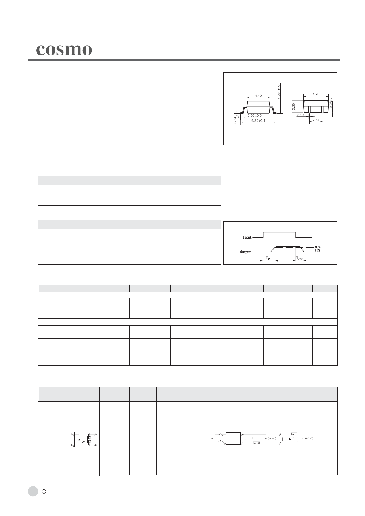
KAQY214S
Unit : mm
±
TOLERANCE :
Turn on/ Turn off time
0.2mm
Electro-optical Characteristics (Ta=25°C)
Parameter Symbol Conditions Min. Typ. Max. Unit
Emitter (Input)
Forward Voltage V
Operation Input Current I
Recovery Input Current I
Detector (Output)
Output Breakdown Voltage V
Output Off-State Leakage I
I/O Capacitance C
ON Resistance R
Turn-On Time T
Turn-Off Time T
F IF =10mA 1.2 1.5 V
FON VL =±20V, IL =100mA, t =10mS 5 mA
FOFF VL =±20V, IL ≤5uA 0.2 mA
B IB=50uA 400 V
TOFF VT =100V, IF =0mA 0.2 1 uA
ISO IF =0, f =1MHZ 6pF
ON IL =100mA, IF =10mA 20 30 Ω
ON IF =10mA, VL =±20V 0.3 1.0 ms
OFF t =10ms, IL =±100mA 0.7 1.5 ms
Mos Relay Schematic and Wiring Diagrams
Type Schematic
KAQY214S 1a AC/DC A
Output
configuration
Load Connection Wiring Diagrams
c 2002 cosmo ELECTRONICS CORPORA TION
116
http://www.cosmo-ic.com
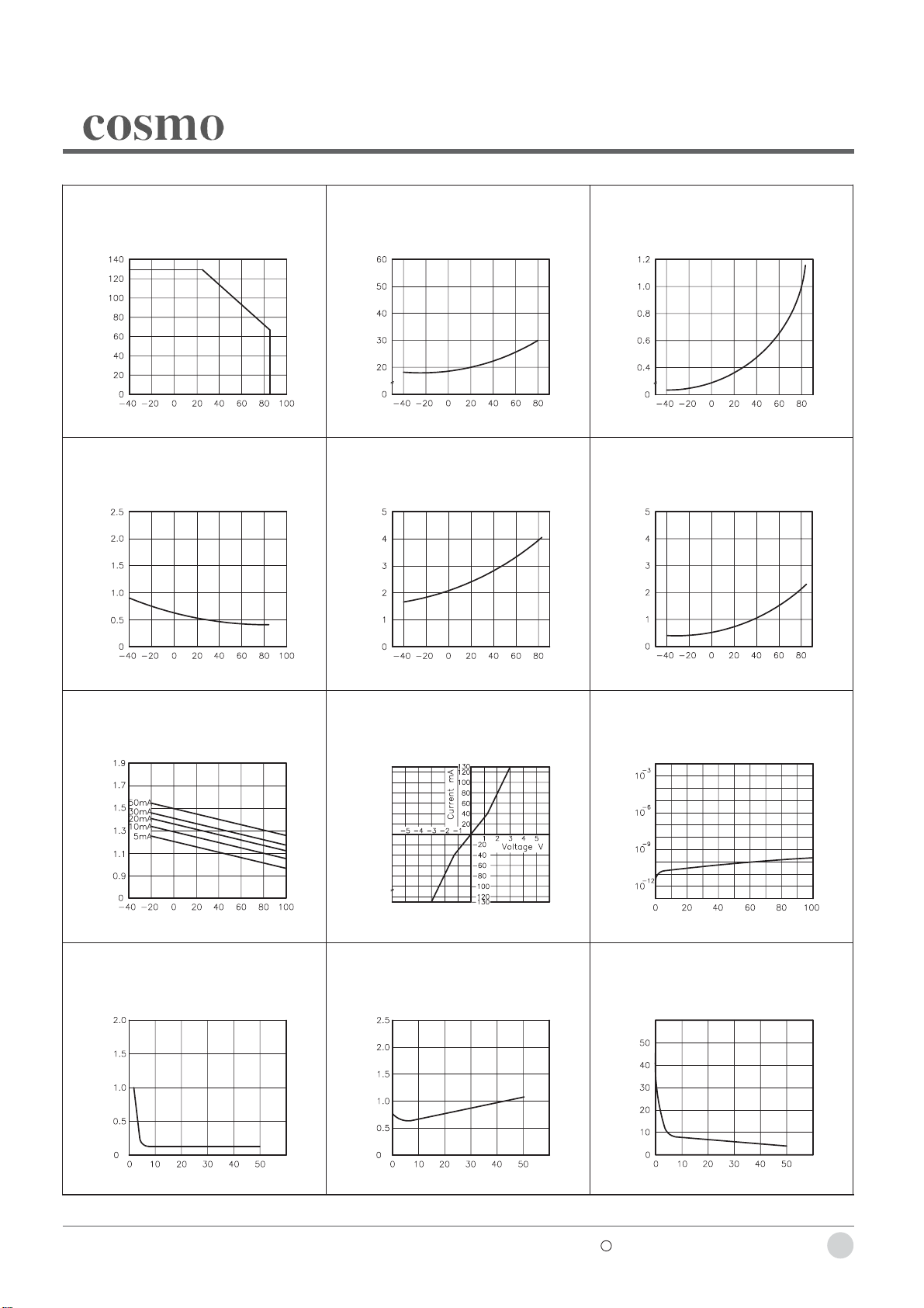
Data Curve
KAQY214S
Fig.1 Load current vs. ambient temperature
Allowable ambient temperature:
-40°C to +85°C
Load Current (mA)
Ambient Temperature Ta (°C)
Fig.4 Turn off time vs. ambient temperature
LED current: 5mA; Load voltage:
400V(DC)
Continuous load current: 130mA(DC)
Tun off Time Msec
Fig.2 On resistance vs. ambient temperature
Across terminals 3 and 4 pin
LED current: 5mA
Continuous load current: 130mA(DC)
On Resistonce (Ω)
Ambient Temperature Ta (°C)
Fig.5 LED operate vs. ambient temperature
Load voltage 400V(DC)
Continuous load current: 130mA(DC)
LED Operate Current (mA)
Fig.3 Turn on time vs. ambient temperature
Load voltage: 400V(DC)
LED current: 5mA
Continuous load current: 130mA(DC)
Turn on Time Msec
Ambient Temperature Ta (°C)
Fig.6 LED turn off current vs. ambient
temperature
Load voltage 400V(DC)
Continuous load current: 130mA(DC)
LED Turn off Current (mA)
Ambient Temperature Ta (°C)
Fig.7 LED dropout voltage vs. ambient
temperature
LED current: 5 to 50mA
LED Dropout Voltage (V)
Ambient Temperature Ta (°C)
Fig.10 LED forward current vs. turn on time
Across terminals 3 and 4 pin;
Load voltage: 400V (DC);
Continuous load current: 130mA (DC);
Ambient temperature: 25°C
Ambient Temperature Ta (°C)
Fig.8 Voltage vs. current characteristics of
output at MOS FET portion
Measured portion: across terminals 3
and 4 pin
Ambient temperature: 25°C
Fig.11 LED forward current vs. turn off time
Across terminals 3 and 4 pin;
Load voltage: 400V (DC);
Continuous load current: 130mA (DC);
Ambient temperature: 25°C
Ambient Temperature Ta (°C)
Fig.9 Off state leakage current
Across terminals 3 and 4 pin
Ambient temperature: 25°C
Off State Leakage Current
Load Voltage (V)
Fig.12 Applied voltage vs. output capacitance
Across terminals 3 and 4 pin
Frequency: 1MHz
Ambient temperature: 25°C
Turn on Time Msec
LED Forward Current (mA)
Turn on Time Msec
LED Forward Current (mA)
Output CapaCitance (pF)
Applied Voltage (V)
c 2002 cosmo ELECTRONICS CORPORATION
http://www.cosmo-ic.com
117
 Loading...