

COSMO KAQV414S Datasheet
E
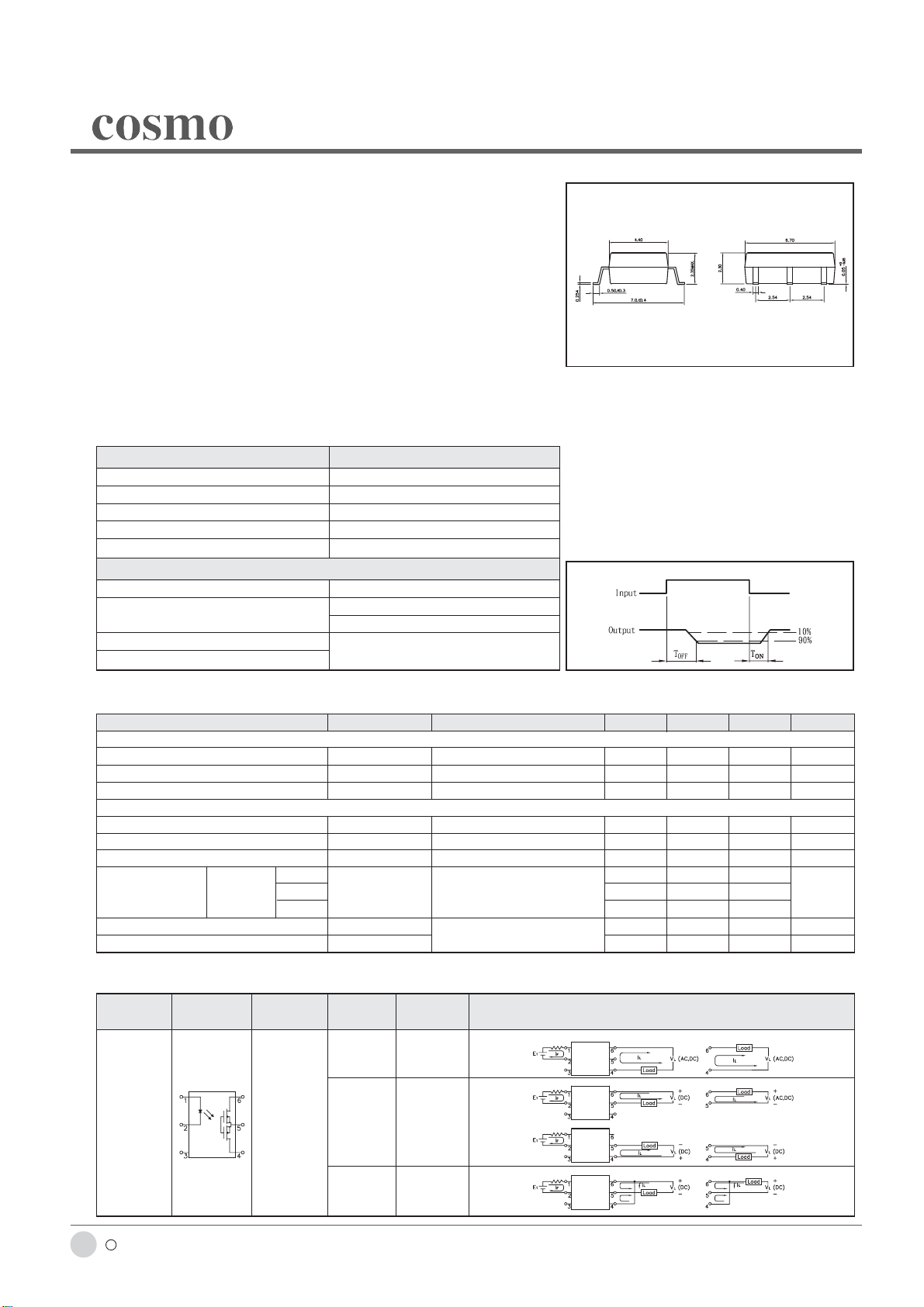
High Voltage, Photo Mos Relay
UL 1577/ UL 508 (File No.E108430), FI EN60950 (File No.FI13698)
D
KAQV414S
Features
1. Normally Close, Single Pole Single Throw
2. Control 400VAC or DC Voltage
3. Switch 130mA Loads
4. LED control Current, 5mA
5. Low ON-Resistance
6. dv/dt, >500V/ms
7. Isolation Test Voltage, 1500VACrms
Absolute Maximum Ratings (Ta=25°C)
Emitter ( Input )
Reverse Voltage……………………………5.0V
Continuous Forward Current ……………50mA
Peak Forward Current ………………………1A
Power Dissipation ……………………100mW
Derate Linearly from 25°C …………1.3mW/°C
General Characteristics
Isolation Test Voltage……………1500VACrms
Isolation Resistance
Vio=500V, Ta=25°C ……………………≥10
Total Power Dissipation ………………550mW
Derate Linearly from 25°C …………2.5mW/°C
Detector ( Output )
Output Breakdown Voltage ……………±400V
Continuous Load Current ……………±130mA
Power Dissipation ……………………500mW
Storage Temperature Range …-40°C to +125°C
Operating Temperature Range…-30°C to +85°C
10
Junction Temperature……………………100°C
Ω
Soldering Temperature,
2mm from case, 10 sec …………………260°C
KAQV414S
Unit : mm
±
TOLERANCE :
Operate/ Reverse time
0.2mm
Electro-optical Characteristics (Ta=25°C)
Parameter Symbol Conditions Min. Typ. Max. Unit
Emitter (Input)
Forward Voltage V
Operation Input Current I
Recovery Input Current I
Detector (Output)
Output Breakdown Voltage V
Output Off-State Leakage I
I/O Capacitance C
A 40 50
ON Resistance Connection B R
C 10 12.5
Reverse (NO) Time T
Operate (OFF) Time T
F IF =10mA 1.2 1.5 V
FOFF VL =±20V, IL ≤5uA 5 mA
FON VL =±20V, IL =100mA, t =10mS 0.2 mA
B IB=50uA 400 V
TOFF
ISO IF =0, f =1MHZ 6pF
ON IL =100mA, IF =10mA 20 25 Ω
ON IF =10mA, VL =±20V 0.6 1.5 ms
OFF t =10ms, IL =±100mA 0.3 1.0 ms
VT =100V, IF =0mA 0.2 2 uA
Mos Relay Schematic and Wiring Diagrams
Type Schematic
KAQV414S 1a DC B
Output
configuration
Load Connection Wiring Diagrams
AC/DC A
c 2002 cosmo ELECTRONICS CORPORA TION
88
http://www.cosmo-ic.com
DC C
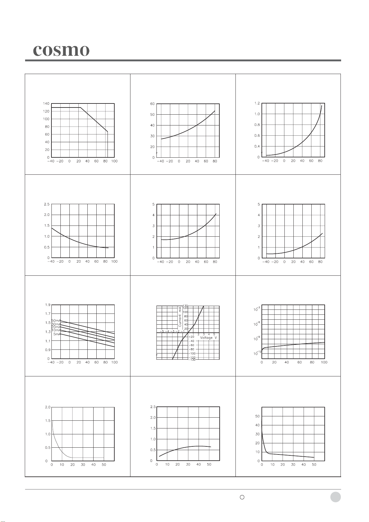
Data Curve
KAQV414S
Fig.1 Load current vs. ambient temperature
Allowable ambient temperature:
-40°C to +85°C
Load Current (mA)
Ambient Temperature Ta (°C)
Fig.4 Reverse (ON) time vs. ambient
temperature LED current: 5mA; Load
voltage: 400V(DC)
Continuous load current: 130mA(DC)
Reverse (ON) Time Msec
Fig.2 On resistance vs. ambient temperature
Across terminals 4 and 6 pin
LED current: 0mA
Continuous load current: 130mA(DC)
On Resistonce (Ω)
Ambient Temperature Ta (°C)
Fig.5 LED operate (OFF) vs. ambient
temperature
Load voltage: 400V(DC)
Continuous load current: 130mA(DC)
LED Operate (OFF) Current (mA)
Fig.3 Operate (OFF) time vs. ambient
temperature Load voltage 400V(DC)
LED current: 5mA
Continuous load current: 130mA(DC)
Operate (OFF) Time Msec
Ambient Temperature Ta (°C)
Fig.6 LED reverse (ON) current vs. ambient
temperature
Load voltage: 400V(DC)
Continuous load current: 130mA(DC)
LED Reverse (ON) Current (mA)
Ambient Temperature Ta (°C)
Fig.7 LED dropout voltage vs. ambient
temperature
LED current: 5 to 50mA
LED Dropout Voltage (V)
Ambient Temperature Ta (°C)
Fig.10 LED forward current vs. operate (OFF)
time Across terminals 4 and 6 pin;
Load voltage: 400V (DC);
Continuous load current: 130mA (DC);
Ambient temperature: 25°C
Ambient Temperature Ta (°C)
Fig.8 Voltage vs. current characteristics of
output at MOS FET portion
Measured portion: across terminals 4
and 6 pin
Ambient temperature: 25°C
Fig.11 LED forward current vs. reverse (ON)
timeAcross terminals 4 and 6 pin;
Load voltage: 400V (DC);
Continuous load current: 130mA (DC);
Ambient temperature: 25°C
Ambient Temperature Ta (°C)
Fig.9 Off state leakage current
Across terminals 4 and 6 pin
Ambient temperature: 25°C
Off State Leakage Current
Load Voltage (V)
Fig.12 Applied voltage vs. output capacitance
Across terminals 4 and 6 pin
Frequency: 1MHz
Ambient temperature: 25°C
Operate (OFF) Time Msec
LED Forward Current (mA)
Reverse (ON) Time Msec
LED Forward Current (mA)
Output CapaCitance (pF)
Applied Voltage (V)
c 2002 cosmo ELECTRONICS CORPORATION
http://www.cosmo-ic.com
89
 Loading...