

Page 1

I N S P I R I N G T H E W O R L D ’ S K I T C H E N
30 IN. DUAL FUEL
FREE- STANDING RANGE
CUISINIÈRE AUTOPORTANTE
À BI-COMBUSTIBLE DE 30 PO
COS-305DFSC
IMPORTANT SAFETY INSTRUCTIONS
Carefully read the following Important information redarding installation
safety and maintenance. Keep these instruction for future reference.
INSTALLATION Instructions
INSTRUCTIONS d’installation
Page 2

RANGE SAFETY ...........................................................................................................
I
NSTALLATION REQUIREMENTS ...............................................................................
Tools and Parts ..........................................................................................................
Location Requirements ..............................................................................................
Electrical Requirements .............................................................................................
Gas Supply Requirements .......................................................................................
I
NSTALLATION INSTRUCTIONS ...............................................................................
Step 1 - Unpack Range ...........................................................................................
Step 2 - Install Anti-Tip Bracket ...............................................................................
Step 3 - Make Electrical Connection ........................................................................
Step 4 - Make Gas Connection .................................................................................
Step 5 - Install Range ...............................................................................................
G
AS CONVERSION ...................................................................................................
Step 1 - Adjust the Gas Pressure Regulator .............................................................
Step 2 - Change Burner Oriÿces ...............................................................................
Step 3 - Adjust Burner Flames .................................................................................
Step 4 - Testing Flame Stability ................................................................................
Step 5 - Flame Re-Check ..........................................................................................
Table of Contents
THANK YOU FOR YOUR PURCHASE.
Thank you for your purchase. We know that you have many brands and
products to choose from and we are honored to know that you have decided
to take one of our products into your home and hope that you enjoy it.
COSMO appliances are designed according to the strictest safety and performance
standard for the North American market. We follow the most advanced
manufacturing philosophy. Each appliance leaves the factory after thorough
quality inspection and testing. Our distributors and our service partners are
ready to answer any questions you may have regarding how to install, use and
care for your products. We hope that this manual will help you learn to use the
product in the safest and most effective manner .
If you have any questions or concerns, please contact the dealer from whom you
purchased it, or contact our Customer Support at:
1-888-784-3108.
Please read the important safety instructions before using our product for
4
7
7
8
11
13
16
16
17
18
22
23
25
27
28
29
30
30
INSTRUCTIONS D’INSTALLATION............................................................ 31
your own safety and to reduce the risk of fire or electrical shock, etc.
Please keep this manual for future use.
THANK YOU
2 3
Page 3

Range Safety
Range Safety
Your safety and the safety of others are very important.
We have provided many important safety messages in this manual
and on your appliance. Always read and obey all safety messages.
This is the safety alert symbol.
This symbol alerts you to potential hazards that can
kill or hurt you and others. All safety messages will
follow the safety alert symbol and either the word
“DANGER,” “WARNING” or “CAUTION.”
These words mean:
An imminently hazardous situation. You
DANGER
WARNING
CAUTION
All safety messages will tell you what the potential hazard is, tell
you how to reduce the chance of injury, and tell you what can
happen if the instructions are not followed.
could be killed or seriously injured if
you don’t immediately follow instructions.
A potentially hazardous situation which, if
not avoided, could result
in death or serious bodily injury.
A potentially hazardous situation
which, if not avoided, may result
in moderate or minor injury.
WARNING
Fire Hazard
If the information in this manual is not followed exactly, a are
or explosion may result causing property damage, personal
injury or death.
- Do not store or use gasoline or other flammable vapors and liquids in
the vicinity of this or any other appliance.
- WHAT TO DO IF YOU SMELL GAS
Do not try to light any appliance.
•
•
Do not touch any electrical switch.
•
Do not use any phone in your building.
•
Clear the room, building, or area of all occupants.
•
Immediately call your gas supplier from a neighbor’s phone.
Follow the gas supplier’s instructions.
•
If you cannot reach your gas supplier, call the fire department.
- Installation and service must be performed by a qualified installer,
service agency or the gas supplier.
WARNING: Gas leaks cannot always be detected by smell.
Gas suppliers recommend that you use a gas detector approved
by UL or CSA.
For more information, contact your gas supplier.
If a gas leak is detected, follow the “What to do if you smell
gas” instructions.
4 5
Page 4

Range Safety
In the State of Massachusetts, the following installation
instructions apply:
Installations and repairs must be performed by a qualified or
•
licensed contractor, plumber, or gasfitter qualified or licensed by
the State of Massachusetts.
If using a ball valve, it shall be a T-handle type.
•
A flexible gas connector, when used, must not exceed 3 feet.
•
State of California Proposition 65 Warnings:
WARNING: This product contains one or more chemicals known
to the State of California to cause cancer.
WARNING: This product contains one or more chemicals known to
the State of California to cause birth defects or other reproductive
harm.
WARNING
ip Over Hazard
T
Installation Requirements
TOOLS AND PARTS
Gather the required tools and parts before starting installation. Read and follow
the instructions provided with any tools listed here.
TOOLS NEEDED
Tape measure
•
Flat-blade screwdriver
•
Phillips screwdriver
•
Level
•
Cordless electric drill
•
Hammer
•
Wrench or pliers
•
Pipe wrench
•
10" Adjustable Wrenches (2)
•
or LP/Natural Gas Conversions
F
½" Combination wrench
•
7 mm combination wrench
•
PARTS SUPPLIED
3/8" nut driver
•
¼" nut driver
•
1/8" (3.2 mm) drill bit (for wood floors)
•
Marker or pencil
•
Masking tape
•
Pipe-joint compound resistant to LP gas
•
a/16" carbide-tipped masonry drill bit
•
(for concrete ceramic floors)
Noncorrosive leak-detection solution
•
7 mm nut driver
•
A child or adult can tip the range and be killed.
Connect anti-tip bracket to rear range foot.
Reconnect the anti-tip bracket, if the range is moved.
Failure to follow these instructions can result in death or serious
burns to children and adults.
6 7
d
c
a 16 x 1 5/8" Screws (2)
b Anti-tip Bracket
OTE: The Anti-tip bracket must be securely mounted to the subfloor.
N
Depending on the thickness of the flooring, longer screws may be
required to anchor the anti-tip bracket to the subfloor. Longer screws are
available from your local hardware store.
c Regulator
d Gas Pipe Adapter
with Washer
Page 5

Installation Requirements
Installation Requirements
PARTS NEEDED
Check local codes and consult gas supplier. Check existing gas supply and
electrical supply. See “Electrical Requirements” and “Gas Supply
Requirements” sections.
Gas Supply Line Kit (Supply line and 2 adapters)
•
LOCATION REQUIREMENTS
VENTILATION
IMPORTANT: Observe all governing codes and ordinances. Do not obstruct
flow of combustion and ventilation air.
It is the installer’s responsibility to comply with installation clearances if
•
specified on the model/serial rating plate. The model/serial rating plate is
located on the left-hand side of the oven frame. Open oven door to view
label. See label on back panel of range for additional element and oven
power ratings.
a
a Rating Plate
GENERAL
The range should be located for convenient use in the kitchen.
•
Recessed installations must provide complete enclosure of the sides and
•
rear of the range.
To eliminate the risk of burns or fire by reaching over heated surface units,
•
cabinet storage space located above the surface units should be avoided. If
cabinet storage is to be provided, the risk can be reduced by installing a
range hood or microwave hood combination that projects horizontally a
minimum of 5" (12.7 cm) beyond the bottom of the cabinets.
All openings in the wall or floor where range is to be installed must be sealed.
•
Do not seal the range to the side cabinets.
•
Grounded electrical supply is required. See “Electrical Requirements” section.
•
Proper gas supply connection must be available. See “Gas Supply
•
Requirements” section.
DIMENSIONS
Product/Opening
Opening dimensions shown are for 25" (64.0 cm) countertop depth, 24" (61.0
cm) base cabinet depth and 36" (91.4 cm) countertop height.
a
5.9" (15 cm)
Min.
Min. 24" (60.9 cm)
Max. 30" (77 cm)
c
a
b
Dimension
30" (76 cm)
29 7/8" (75.9 cm)
TEMPERATURE
IMPORTANT: Some cabinet and building materials are not designed to
withstand the heat produced by the oven for baking and self-cleaning. Check
with your builder or cabinet supplier to make sure that the materials used will
not discolor, delaminate or sustain other damage.
Contact a qualified floor covering installer to check that the floor covering
•
can withstand at least 200°F (93°C).
Use an insulated pad or ¼" (0.64 cm) plywood under range if installing range
•
over carpeting.
8 9
c
ed
d
e
25" (63.5 cm)
36" (91.4 cm)
37 3/4" (96 cm)
b
N
OTE: Range can be raised approximately 1" (2.5 cm) by adjusting the leveling
legs. Front of door and drawer may extend farther forward depending on styling.
Page 6

Back of Range
a
b
c
a
Access Panel to Electrical
Supply Connection
b
Power Cord Opening
c
Recessed area
P
ower Supply
IMPORTANT: An electrical outlet in the floor, may be either recessed or surface
mounted, but an electrical outlet in the wall must be recessed to make the
connection. For Direct Wiring, the electrical box should be mounted to the wall.
a
b
e
d
g
h
c
f
a
30" (76 cm)
b
11½" (29.2 cm)
c
6" (15.2 cm)
d
7¼" (18.4 cm)
e
3" (7.6 cm)
f
17½" (44 cm)
g
Recommended Location for
Electrical Outlet
h
Recommended Location
for Gas Supply Connection
Installation Requirements
8
9
ELECTRICAL REQUIREMENTS
IMPORTANT: Use a 3-wire, UL listed, 30-amp minimum supply cord (pigtail);
or if local codes do not permit grounding through the neutral, use a 4-wire UL
listed, 30-amp minumum power supply cord rated at 250 volts and intended
for use with ranges.
If codes permit and a separate ground wire is used, it is recommended that
a qualified electrical installer determine that the ground path is adequate
and wire gauge is in accordance with local codes.
To properly install your range, you must determine the type of electrical
connection you will be using and follow the instructions provided for it here.
•
Range must be connected to the proper electrical voltage and frequency as
specified on the model/serial number rating plate. All models are dual rated,
and designed to be connected to either 120/240V or 120/208V AC, 60Hz,
single-phase, 3-wire or 4-wire, power supply.
Voltage and
Frequency
Amps Circuit Required
240V, 60 Hz 20A
25 Amp Circuit
208V, 60 Hz 17.4A
20 Amp Circuit
•
When a 4-wire, single-phase 120/240 volt, 60 Hz., AC only electrical
supply is available, a 25-amp maximum circuit protection is required (or, if
specified on the model/serial rating plate, when a 4-wire, single phase
120/208 volt 60 Hz., AC only electrical supply is available, a 20-amp
maximum circuit protection is required).
•
For direct wire installations, install a suitable conduit box (not furnished).
An appropriately sized, UL conduit connector must be used to correctly
attach the conduit to the junction box.
I
MPORTANT: Local Codes may vary; installation electrical connections
and grounding must comply with all applicable local codes.
If local codes permit grounding through the electrical supply neutral, connect
both the white neutral wire and the green ground wire from the oven to the
white neutral electrical supply wire.
ELECTRICAL REQUIREMENTS - U.S.A. ONLY
Do not use an extension cord.
Be sure that the electrical connection and wire size are adequate and in
conformance with the National Electrical Code, ANSI/ NFPA No. 70-latest
edition and all local codes and ordinances.
A copy of the above code standards can be obtained from:
National Fire Protection
Association One Batterymarch
Park
Quincy, MA 02269
Installation Requirements
NOTE: 24" (61.0 cm) minimum clearance required when bottom of wood or metal
cabinet is covered by not less than ¹/₄" (0.64 cm) flame retardant millboard
covered with not less than No. 28 MSG sheet steel, 0.015" (0.4 mm) stainless
steel,
0.024" (0.6 mm) aluminum or 0.020" (0.5 mm) copper. 30" (76.2 cm) minimum
clearance between the cooking and the bottom of an uncovered wood or metal
cabinet.
10 11
Page 7

WARNING
10
E
lectrical Shock Hazard
The electrical power to the oven branch circuit must be shut off
while line connections are being made.
Do not use an extension cord with this appliance.
Electrical ground is required on this appliance. The free end of the
green wire (the ground wire) must be connected to a suitable
ground. This wire must remain grounded to the oven.
If cold water pipe is interrupted by plastic, non metallic gaskets,
union connections or other insulating materials, DO NOT use for
grounding.
DO NOT ground to a gas pipe.
DO NOT have a fuse in the NEUTRAL or GROUNDING circuit. A
fuse in the NEUTRAL or GROUNDING circuit could result in an
electrical shock.
Check with a qualified electrician if you are in doubt as to whether the
appliance is properly grounded.
Failure to do so could result in death, fire or electric shock.
ELECTRICAL REQUIREMENTS - CANADA ONLY
Electrical Shock Hazard
Disconnect power before servicing.
Plug into a grounded outlet.
Do not use an extension cord.
Failure to do so can result in death, fire, or electrical shock.
Be sure that the electrical connection and wire size are adequate and in
conformance with CSA Standard C22.1, Canadian Electrical Code, Part 1 latest edition, and all local codes and ordinances.
Installation Requirements
WARNING
A copy of the above code standards can be obtained from:
Canadian Standards
Association 178 Rexdale Blvd.
Toronto, ON M9W 1R3
CANADA.
•
Check with a qualified electrical installer if you are not sure the range is
properly grounded.
•
This range is equipped with a CSA International Certified Power Cord
intended to be plugged into a standard 14-50R wall receptacle. Be sure the
wall receptacle is within reach of range’s final location.
•
Do not use an extension cord.
GAS SUPPLY REQUIREMENTS
Explosion Hazard
Use a new CSA International approved gas supply line.
Install a shut-off valve.
Securely tighten all gas connections.
If connected to LP, have a qualified person make sure gas
pressure does not exceed 14" (36 cm) water column.
Examples of a qualified person include:
licensed heating personnel,
authorized gas company personnel, and
authorized service personnel.
Failure to do so can result in death, explosion or fire.
Observe all governing codes and ordinances.
Installation Requirements
WARNING
12 13
Page 8
12
IMPORTANT: This installation must conform with all local codes and
ordinances. In the absence of local codes, installation must conform with
American National Standard, National Fuel Gas Code ANSI Z223.1 - latest
edition or CAN/CGA B149 – latest edition.
I
MPORTANT: Leak testing of the range must be conducted according to
the manufacturers instructions.
TYPE OF GAS
Natural gas:
This range is design-certified by CSA International for use with Natural gas or,
after proper conversion, for use with LP gas.
•
This range is factory set for use with Natural gas. See “Gas Conversions”
section. The model/serial rating plate located on the right side oven door
trim has information on the types of gas that can be used. If the types of gas
listed do not include the type of gas available, check with the local gas supplier.
L
P gas conversion:
IMPORTANT: Conversion must be done by a qualified service technician.
No attempt shall be made to convert the appliance from the gas specified on
the model/serial rating plate for use with a different gas without consulting the
serving gas supplier. See “Gas Conversions” section.
GAS SUPPLY LINE
Provide a gas supply line of ¾" (1.9 cm) rigid pipe to the range location. A
smaller size pipe on longer runs may result in insufficient gas supply. Pipe-joint
compounds that resist the action of LP gas must be used. With LP gas, piping
or tubing size can be ½" (1.3 cm) minimum. Usually, LP gas suppliers determine
the size and materials used in the system.
G
as Shut-off Valve:
•
The gas supply line must be equipped with a manual shutoff valve. This valve
should be located in the same room but external to the range. It should be
in a location that allows ease of opening and closing. Do not block access
to shutoff valve. The valve is for turning on or shutting off gas to the range.
a b c
a Gas Supply Line
b Shutoff Valve “Open” Position
c Flexible/Rigid Gas Line to Range
Installation Requirements
13
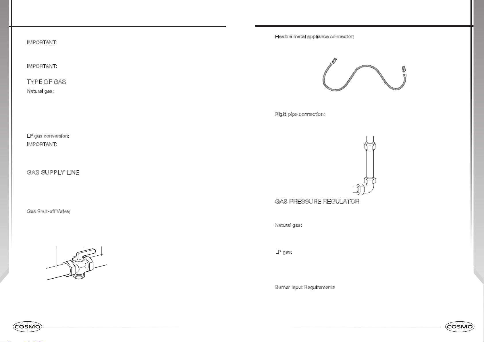
Flexible metal appliance connector:
•
If local codes permit, a new CSA design-certified, 4 - 5 ft (122 - 152.4 cm) long,
1/2" (1.3 cm) or 3/4" (1.9 cm) I.D., flexible metal appliance connector may
be used for connecting range to the gas supply line.
•
A ½" (1.3 cm) male pipe thread is needed for connection to the female
pipe threads of the inlet to the appliance pressure regulator.
•
Do not kink or damage the flexible metal tubing when moving the range.
R
igid pipe connection:
The rigid pipe connection requires a combination of pipe fittings to obtain an
in-line connection to the range. The rigid pipe must be aligned with the range
connection. All strains must be removed from the supply and fuel lines so
range will be level and in line.
GAS PRESSURE REGULATOR
The gas pressure regulator supplied with this range must be used. The inlet
pressure to the regulator should be as follows for proper operation:
N
atural gas:
Minimum pressure: 5" WCP
Maximum pressure: 14" WCP
L
P gas:
Minimum pressure: 11" WCP
Maximum pressure: 14" WCP
Contact local gas supplier if you are not sure about the inlet pressure.
B
urner Input Requirements
Input ratings shown on the model/serial rating plate are for elevations up to
2,000 ft (609.6 m).
For elevations above 2,000 ft (609.6 m), ratings are reduced at a rate of 4% for each
1,000 ft (304.8 m) above sea level (not applicable for Canada).
Installation Requirements
14 15
Page 9

14
GAS SUPPLY PRESSURE TESTING
Line pressure testing above 0.5 psi gauge (14. WCP)
The range and its individual shutoff valve must be disconnected from the gas
supply piping system during any pressure testing of that system at test
pressures in excess of 0.5 psi (3.5 kPa).
L
ine pressure testing at 0.5 psi gauge (14" WCP) or lower
The range must be isolated from the gas supply piping system by closing its
individual manual shutoff valve during any pressure testing of the gas supply
piping system at test pressures equal to or less than 0.5 psi (3.5 kPa).
I
MPORTANT: This appliance shall be installed only by authorized persons
and in accordance with the manufacturer’s installation instructions, local
gas fitting regulations, municipal building codes, electrical wiring
regulations, local water supply regulations.
STEP 1 - UNPACK RANGE
Excessive Weight Hazard
Use two or more people to move and install range. Failure to
do so can result in back or other injury.
1. Remove shipping materials, tape and film from the range. Keep
cardboard bottom under range. Do not dispose of anything until the
installation is complete.
2
. Remove oven racks and parts package from oven and shipping materials.
3
. To remove cardboard bottom, first take 4 cardboard corners from the
carton. Stack one cardboard corner on top of another. Repeat with the
other 2 corners. Place them lengthwise on the floor behind the range to
support the range when it is laid on its back.
4
. Using two or more people, firmly grasp the range and gently lay it on its
back on the cardboard corners.
5
. Remove cardboard bottom.
N
OTES:
•
The leveling legs can be adjusted while the range is on its back.
•
To place range back up into a standing position, put a sheet of cardboard
or hardboard on the floor in front of range to protect the flooring. Using two
or more people, stand range back up onto the cardboard or hardboard.
Installation Requirements
Installation Instructions
WARNING
WARNING
STEP 2 - INSTALL ANTI-TIP BRACKET
Tip Over Hazard
A child or adult can tip the range and be killed.
Connect anti-tip bracket to rear range foot.
Reconnect the anti-tip bracket, if the range is moved.
Failure to follow these instructions can result in death or serious
burns to children and adults.
IMPORTANT: An anti-tip bracket kit is included with the range. The anti-tip bracket
uses either the right or left rear leveling leg to secure the range to the floor.
1. Remove the anti-tip bracket from where it is taped inside the oven or storage
drawer.
2.
NOTE: The anti-tip bracket can be installed on either the left-hand side or
right-hand side of the opening.
3. Place the anti-tip bracket onto the floor so that the distances from the
center of the bracket to the center line and to the wall is correct for your
model.
•
Center of Opening to Center of Bracket: 13½" (34.3 cm)
•
4. Drill two 1/8" (3 mm) holes through the mounting holes in the anti-tip
bracket and into the floor.
NOTE: Contact a qualified floor covering installer for the best procedure
for drilling mounting holes through your type of floor covering.
5. Using the two screws provided, secure the anti-tip bracket to the floor.
NOTE: A rear leg of the range will be centered within the anti-tip bracket
when it is moved into its final position.
Installation Instructions
Determine and mark centerline of the opening where the unit will be installed.
Wall to Top of Bracket - 3 5/16" (8.e cm)
16 17
Page 10

Installation Instructions
Installation Instructions
DIRECT WIRE - U.S.A ONLY
STEP 3 - MAKE ELECTRICAL CONNECTION
After reading the requirements for each connection method, follow the
electrical connection instructions specific to your situation.
POWER SUPPLY CORD - CANADA ONLY
WARNING
Electrical Shock Hazard
Plug into a grounded outlet.
Do not use an extension cord.
Failure to do so can result in death, fire, or electrical shock.
1. Plug into a standard 14-50R grounded wall receptacle.
2
. Go to STEP 4 - MAKE GAS CONNECTION.
WARNING
Electrical Shock Hazard
Disconnect power before servicing.
Improper connection of aluminum house wiring and copper
appliance leads can result in an electrical hazard or fire. If the home
has aluminum wiring, only use connectors designed and UL listed
for joining copper to aluminum and precisely follow the
manufacturer's recommended procedure. Aluminum-to-Copper
connections must conform with local codes.
Use 10 gauge copper or aluminum wire.
Electrically ground range.
Failure to do so can result in death, fire or electrical shock.
Be sure your appliance is properly installed and grounded by a qualified
technician. Ask your dealer to recommend a qualified technician or an
authorized repair service.
This range is manufactured with a neutral (white) power supply wire and a
cabinet-connected green (or bare) ground wire twisted together.
After making sure that the power has been turned off, connect the flexible
conduit from the range to the junction box using a UL listed conduit connector.
The Grounded Neutral and Ungrounded Neutral Graphics on the following
pages and the instructions provided, present the most common way of
connecting ranges. Your local codes and ordinances, of course, take
precedence over these instructions. Complete electrical connections according
to local codes and ordinances.
18 19
Page 11

Installation Instructions
Installation Instructions
3-WIRE CONNECTION (GROUNDED NEUTRAL) - U.S.A. ONLY.
WARNING
Electrical Shock Hazard
Grounding through the neutral conductor is prohibited for new
branch-circuit installations (1996 NEC); mobile homes; and
recreational vehicles, or in an area where local codes prohibit
grounding through the neutral conductor. For installations where
grounding through the neutral conductor is prohibited, see the
Ungrounded Neutral graphic.
Use grounding terminal or lead to ground unit.
Connect neutral terminal or lead to branch circuit neutral in
usual manner.
Failure to do so could result in death, fire or electric shock.
3-Wire Cable from Home Power Supply
IMPORTANT: Use the 3-wire cable from home power supply where local codes
permit a 3-wire connection.
1
. Disconnect power.
rounded Neutral
G
a
i
2.
Connect the 2 black wires
.
3
Connect the 2 neutral (white) wires
(of the range cable) using a UL listed wire connector.
.
4
Connect the 2 red wires g together using a UL listed wire connector.
. Install junction box cover.
5
4-WIRE CONNECTION (UNGROUNDED NEUTRAL)- U.S.A. ONLY
4-Wire Cable from Home Power Supply
IMPORTANT: Use the 4-wire cable from home power supply in the U.S. where
local codes do not allow grounding through neutral, New Branch circuit
installations (1996 NEC), mobile homes and recreational vehicles, new
construction and in Canada.
. Disconnect power.
1
a
b together using a UL listed wire connector.
c and the ground (green or bare) wire d
U
ngrounded Neutral
i
b
h
c
g
f
e
d
a Junction Box
b Black Wires
c Neutral (White)
Wires
b
c
d
e
d Ground (Green or
Bare) Wire
e Cable from Range
f UL Listed Conduit
Connector
h
g
f
g Red Wires
h UL Listed Wire Connectors
i House Electrical Supply
20 21
a Junction Box
b Black Wires
c Red Wires
d Cable from Range
2
.
Connect the 2 black wires b together using a UL listed wire connector.
.
3
Connect the 2 red wires
. Untwist white wire from green (or bare) ground wire coming from the range.
4
.
5
Connect the 2 neutral (white) wires
wire connector.
6
.
Connect the ground (green or bare) wire
ground (green or bare) wire (in the junction box) using a UL listed wire
connector.
. Install junction box cover.
7
e UL listed or CSA
Approved Conduit
Connector
f Ground (Green or
Bare) Wires
c together using a UL listed wire connector.
h together using a UL listed
f from the oven cable to the
g UL Listed Wire
Connector
h Neutral (White) Wires
i House Electrical Supply
Page 12

Installation Instructions
Installation Instructions
STEP 4 - MAKE GAS CONNECTION
WARNING
Explosion Hazard
Use a new CSA International approved gas supply line.
Install a shut-off valve.
Securely tighten all gas connections.
If connected to LP, have a qualified person make sure gas
pressure does not exceed 14" (36 cm) water column.
Examples of a qualified person include:
licensed heating personnel,
authorized gas company personnel, and
authorized service personnel.
Failure to do so can result in death, explosion or fire.
TYPICAL FLEXIBLE CONNECTION
CONNECT BSPP TO NPT ADAPTER TO GAS REGULATOR:
1. Apply pipe-joint compound made for use with LP gas to the male threads of
adapter c.
2
.
Insert adapter c into outlet of the gas pressure regulator d, and then
tighten
regulator is pointing up toward the range gas inlet pipe.
.
3
Install washer b in female end of adapter c, and then connect adapter
c
N
using two 10" adjustable wrenches. Be sure flow arrow
to range gas inlet pipe a via compression fitting and tighten.
OTE: Washer b must be used to create a leak proof seal.
on
CONNECT GAS LINE FROM GAS PRESSURE REGULATOR TO GAS SUPPLY:
1. Apply pipe-joint compound made for use with LP gas to the tapered (NPT)
threads of both adapters
. Attach one adapter to the gas pressure regulator and the other to the
2
gas shutoff valve and tighten both.
N
OTE: Do Not rotate the gas pressure regulator.
3
.
Attach the flexible gas line c to adapters d, one adapter at each end.
IMPORTANT: All connections must be wrench tightened (requires two 10"
adjustable wrenches). Do not over-tighten the connections to the gas pressure
regulator. Overtightening may crack the regulator creating a leak.
supplied with gas line kit.
d
e
a
d
a Adapter (provided)
b Gas Pressure Regulator
c Gas Supply Line
b
c
d
COMPLETE CONNECTION
1. Open the manual shutoff valve in the gas supply line. The valve is open when the
handle is parallel to the gas pipe.
2
. Test all connections by brushing on an approved noncorrosive leak-
detection solution. If bubbles appear, a leak is indicated. Correct any leak
found.
. Plug in range or reconnect power.
3
d Adapters (From Gas
Supply Line Kit)
e Gas Shutoff Valve
a
b
c
d
a Gas Line from Range
b Washer (provided)
c Adapter (provided)
d Gas Pressure Regulator
(provided)
STEP 5 - INSTALL RANGE
IMPORTANT: If the range is moved to adjust the leveling legs, make sure
when you move the range back into its final location that the anti-tip bracket is
engaged by repeating steps 1 through 8.
1
2
22 23
. Slide range into final location, making sure rear leveling leg slides into anti-
tip bracket. Leave a 1" (2.5 cm) gap between the back of the range and the
back wall.
. Place the outside of your foot against the bottom front to keep the range
from moving, and then grasp the back of the range, as shown.
Page 13

3. Slowly attempt to tilt the range forward.
If you encounter immediate resistance, the range foot is engage
d in the
anti-tip bracket. Go to Step 9.
4
. If the rear of the range lifts more than 1/2" (1.3 cm) off the floor without
resistance, stop tilting the range and lower it gently back to the floor. The
range foot is not engaged in the anti-tip bracket.
I
MPORTANT: If there is a snapping or popping sound when lifting the range,
the range may not be fully engaged in the bracket. Check to see if there are
obstructions keeping the range from sliding to the wall or keeping the range
foot from sliding into the bracket. Verify that the bracket is held securely in
place by the mounting screws.
5
. Slide the range forward, and verify that the anti-tip bracket is securely
attached to the floor or wall.
6
. Slide range back so the rear range foot is inserted into the slot of the
anti-tip bracket.
7
. Repeat steps 1 through 3 to ensure that the range foot is engaged in the
anti-tip bracket.
If the rear of the range lifts more than
1/2" (1.3 cm) off the floor without
resistance, the anti-tip bracket may not be installed correctly. Do not
operate the range without anti-tip bracket installed and engage
d.
8
. Move the range into its final location, and check that the range is level by
placing a carpenter’s level on the bottom of the oven.
N
OTE: The range must be level for optimum cooking and baking
performance.
9
. If needed, use a wrench to adjust the height of the leveling legs until the
range is level from side to side and front to back.
Installation Instructions
Gas Conversion
WARNING
Explosion Hazard
Use a new CSA International approved gas supply line.
Install a shut-off valve.
Securely tighten all gas connections.
If connected to LP, have a qualified person make sure gas
pressure does not exceed 14" (36 cm) water column.
Examples of a qualified person include:
licensed heating personnel, authorized
gas company personnel, and
authorized service personnel.
Failure to do so can result in death, explosion or fire.
24 25
LP/PROPANE GAS CONVERSION
This appliance can be used with Natural Gas or LP/Propane gas. It is shipped
from the factory for use with natural gas.
be purchased separately.
When the cooktop is converted for liquid petroleum (LP) gas, the LP gas
supply is required to provide a minimum of 10" to a maximum of 14" water
column to the cooktop regulator.
The conversion must be performed by a qualified service technician in
accordance with the kit instructions and all local codes and requirements.
Failure to follow instructions could result in serious injury or property damage.
The qualified agency performing this work assumes responsibility for the
conversion.
A kit for converting to LP gas must
Page 14

Gas Conversion
Burner and Orifice Characteristic Table
Burner Position
Auxiliary Rear R 0.9 NG 4" 3500
Semi-Rapid Rear L and
Triple Front L 0.93 + 1.82 NG 4" 18000
Rapid Front R 1.6 NG 4" 11000
OTE: The triple burner has only two injectors, one injector mounted in the
N
center and one mounted below the cover plate. To access the second injector,
remove the two screws and the cover plate.
Center
Orifice Gas Pressure Rate
Diam. (mm) Type [i.w.c.] [BTU/h]
0.58 LP (Propane) 10" 3500
1.17 NG 4" 6000
0.75 LP (Propane) 10" 6000
1.14 + 0.56 LP (Propane) 10" 18000
1.03 LP (Propane) 10" 11000
Gas Conversion
STEP 1 - ADJUST THE GAS PRESSURE REGULATOR
IMPORTANT: Disconnect all electrical power, at the main circuit breaker or fuse
box. Shut off the gas supply to the range by closing the manual shut-off valve.
1
. Unscrew the regulator cap with the wrench.
a
a Regulator Cap
. Remove the retainer pin that is currently positioned for use with Natural Gas.
2
a
a
a Opening in grate for wok ring (provided) is located over left front burner.
ools Needed for Conversion:
T
Wrench
•
7 mm Nut Driver
•
Safety Glasses
•
Small Flat-head Screwdriver
•
. Turn the retainer pin upside down and replace it into the regulator cap. It is
3
. Screw the regulator cap back into the regulator.
4
26 27
a Retainer Pin
now positioned for use with LP gas.
a
a Retainer Pin
Page 15

Gas Conversion
Not Properly SeatedProperly Seated
STEP 3 - ADJUST BURNER
F
LAMES
NOTES:
•
Turn all burners on highest setting and check the flames. They should be
blue in color and may have some yellow tipping at the ends of the flame
when using LP gas. Foreign particles in the gas line may cause an orange
flame at first, but this will soon disappear.
•
Turn the cooktop burner knob to “LO” while observing the flame.
•
Adjustments must be made with two other burners in operation on a medium
setting. This prevents the upper row of flames from being set too low,
resulting in the flame being extinguished when other burners are turned on.
1
. Remove the knobs.
2
. Insert a screwdriver through the access hole in valve shaft as shown.
3
. Slowly turn the screw until the flame appearance is correct.
•
Open the valve more if the flames are too small or fluttered.
•
Close the valve more if the flames are too large.
Gas Conversion
STEP 4 - TESTING FLAME STABILITY
Test 1 - Turn the knob from “HI” to “LO” quickly. If the upper row of flames
goes out at this setting, increase the flame size and test again.
T
est 2 - With the burner on “LO”, open and close the cabinet door under
the cooktop. If the air currents created by the door moving extinguish
the flame, increase the flame height and test again.
STEP 5 - FLAME RE-CHECK
After the adjustment is made, turn all burners off. Ignite each burner individually.
Observe the flame at the “HI” position. Rotate the knob to the lowest setting and
be sure that the flame size decreases as the knob is rotated counterclockwise.
STEP 2 - CHANGE BURNER ORIFICES
IMPORTANT: Carefully read and observe each orifice label for correct location.
See the Burner Chart earlier in this section.
N
OTE: First remove all orifices and then start replacing them. This will help avoid
the possibility that some may not be replaced.
1
. Remove the burner grates, burner caps and burner heads.
. Using a 7mm nut driver, remove the burner orifices.
2
a Orifices
a
Triple Ring Burner
2 Orifices
3. Install the proper orifices in the exact locations as noted in the previous graphic.
4. Replace the burner bases, heads, caps and top grates. Make sure burner
caps are properly seated on the burner head.
a
Auxiliary Burner Semi-Rapid
Burner Rapid Burner
1 Orifice Each
28 29
Page 16

Gas Conversion
IMPORTANT: Once the conversion has been completed and has passed
testing, fill out the conversion sticker and include your name, organization
and the date conversion is made. Apply the sticker near the cooktop gas inlet
opening to alert others in the future that this appliance has been converted. If
converting back to Natural Gas, please remove the sticker so others know
that the appliance is set to use its original gas.
ABNORMAL OPERATION
ANY OF THE FOLLOWING ARE CONSIDERED TO BE ABNORMAL
OPERATION AND MAY REQUIRE SERVICING:
Yellow tipping of the hob burner flame.
•
Sooting up of cooking utensils.
•
Burners not igniting properly.
•
Burners failing to remain lit.
•
Burners extinguished by oven door.
•
Gas valves, which are difficult to turn.
•
I
N CASE THE APPLIANCE FAILS TO OPERATE CORRECTLY, CONTACT THE
UTHORIZED SERVICE PROVIDER IN YOUR AREA
A
THE BURNERS REQUIRE NO REGULATION OF THE PRIMARY AIR
Circuit Diagram
Low
Top Grill
Back grill
Bottom Grill
120 Therma l cut off
Cool fan
Cyc
High
Cool fan
M1
M2 M3
Lamp
Latch
fan
M4
85 Therma l cut off
Table des Matières
SÉCURITÉ DE LA CUISINIÈRE .................................................................................. 30
EXIGENCES D’INSTALLATION .................................................................................. 32
Outillage et pièces .....................................................................................................32
Exigences d’emplacement ........................................................................................33
Spécifications électriques .........................................................................................37
Exigences de l’alimentation en gaz ..........................................................................40
I
NSTRUCTIONS D’INSTALLATION .......................................................................... 43
Étape 1 - Déballage de la cuisinière ........................................................................43
Étape 2 - Installation de la bride antibasculement ...................................................44
Étape 3 - Raccordement électrique .........................................................................45
Étape 4 - Raccordement au gaz .............................................................................50
Étape 5 - Installation de la cuisinière ......................................................................52
C
ONVERSION POUR CHANGEMENT DE GAZ ....................................................... 53
Étape 1 – Réglage du détendeur ..............................................................................55
Étape 2 – Remplacement des orifices des brûleurs .................................................56
Étape 3 – Réglage des flammes des brûleurs ..........................................................57
Étape 4 – Test de la stabilité des flammes ...............................................................58
Étape 5 – Second test des flammes .........................................................................58
L1(RED)
N(WHITE)
L2(BLACK)
G(GREEN)
A68A67
L1
A53
A65
A10
A43
A12
A52
A66
A54A55
A42
L2
L2
L
L
L1
2
1
Latch2
GND
Latch_door1
Baffle
Latch1
DOOR
TO_DISP
UP_HT_CUT
L
L
a
PCB BOARD
MI
CA
down sensor
GA
CA
CA
CA
at
DOOR
tch1
GND
c
h2
up sensor
Latch_door2
CA
LN
POWER
TO_SW
GND
Probe
GND
Probe
GND
Baffle
probe_down probe_up
PCB BOARD
A Plug
B Plug
DISPLAY
Probe socket
30 31
Page 17

Sécurité de la Cuisinière
Votre sécurité et celle des autres est très importante.
Nous donnons de nombreux messages de sécurité importants
dans ce manuel et sur votre appareil ménager. Assurez-vous de
toujours lire tous les messages de sécurité et de vous y conformer.
Voici le symbole d’alerte de sécurité.
Ce symbole d’alerte de sécurité vous signale les
dangers potentiels de décès et de blessures graves
à vous et à d’autres. Tous les messages de sécurité
suivront le symbole d’alerte de sécurité et le mot
“DANGER”, “AVERTISSEMENT” ou “ATTENTION”.
Ces mots signifient :
Une situation de danger
DANGER
AVERTISSEMENT
ATTENTION
Tous les messages de sécurité vous diront quel est le danger
potentiel et comment réduire le risque de blessure et ce qui peut
se produire en cas de non-respect des instructions.
imminent. Vous courez le risque
d’un décès ou de blessures
graves si vous ne suivez pas
immédiatement les instructions.
Une situation potentiellement
dangereuse qui, si vous ne
l’évitez pas, peut provoquer la
mort ou des blessures graves.
Une situation potentiellement
dangereuse qui, si vous ne
l’évitez pas, peut entraîner des
blessures légères à modérées.
Sécurité de la Cuisinière
AVERTISSEMENT
Risque d'incendie
Si les informations figurant dans ce manuel ne sont pas suivies à
la lettre, il peut en résulter un incendie ou une explosion pouvant
causer des dégâts matériels, des blessures, voire un décès.
- Ne pas ranger et utiliser d’essence ou d’autres vapeurs et liquides
inflammables à proximité de cet appareil ou d’un autre appareil.
- QUE FAIRE SI VOUS SENTEZ UNE ODEUR DE GAZ
Ne pas essayer d’allumer un appareil.
•
Ne pas toucher d’interrupteur électrique.
•
Ne pas utiliser de téléphone dans votre bâtiment.
•
Faire évacuer tous les occupants de la pièce, du bâtiment ou
•
de la zone concernée.
Appeler immédiatement votre fournisseur de gaz depuis chez un
•
voisin. Suivre les instructions de votre fournisseur de gaz.
Si le fournisseur de gaz ne peut être rejoint, appeler les pompiers.
•
- L’installation et la maintenance doivent être confiées à un installateur
qualifié, à un réparateur agréé ou au fournisseur de gaz.
32 33
AVERTISSEMENT : L’odorat ne permet pas toujours la
détection d’une fuite de gaz.
Les distributeurs de gaz recommandent l’emploi d’un détecteur de
gaz (homologation UL ou CSA).
Pour d’autre information, contacter le fournisseur de gaz local.
En cas de détection d’une fuite de gaz, exécuter les instructions
“Que faire dans le cas d’une odeur de gaz”.
Page 18

•
Clé mixte de 7 mm
Sécurité de la Cuisinière
AVERTISSEMENT
Risque de basculement
Un enfant ou une personne adulte peut faire basculer la cuisinière
ce qui peut causer un décès.
Joindre la bride antibasculement au pied arrière de la cuisinière.
Joindre de nouveau la bride antibasculement si la cuisinière
est déplacée.
Le non-respect de ces instructions peut causer un décès ou
des brûlures graves aux enfants et aux adultes.
Exigences d'installation
OUTILLAGE ET PIÈCES
Rassembler les outils et composants nécessaires avant d’entreprendre
l’installation. Lire et observer les instructions fournies avec chacun des outils de
la liste ci-dessous.
OUTILS NÉCESSAIRES
Mètre enrouleur
•
Tournevis à lame plate
•
Tournevis Phillips
•
Niveau
•
Perceuse électrique sans fil
•
Marteau
•
Clé ou pince
•
Clé à tuyauterie
•
Clés à molette de q0" (2)
•
Tourne-écrou de 3/8"
•
Pour conversions pour GPL / gaz naturel
Clé mixte de 1/2"
•
Tourne-écrou de 1/4"
•
Foret de 1/8" (3,2 mm) (pour
•
planchers en bois)
Marqueur ou crayon
•
Ruban adhésif de masquage
•
Composé d’étanchéité des raccords
•
filetés – résistant au GPL
Foret à maçonnerie à pointe carburée
•
de i/16" (4,8 mm) (pour planchers en
bétons céramique)
Solution non corrosive de détection
•
des fuites
Tourne-écrou de 7 mm
•
Exigences d'installation
PIÈCES FOURNIES
d
e
c
a Vis de 16 x 1 5/8” (2)
b La bride antibasculement
EMARQUE : Les brides antibasculement doivent être solidement fixées
R
au sous-plancher. La profondeur du plancher peut nécessiter des vis plus
longues pour l’ancrage de la bride dans le sous-plancher. Des vis plus
longues sont disponibles auprès de votre quincaillerie locale.
c Détendeur
d Adaptateur pour
conduite de gaz
avec rondelle
PIÈCES NÉCESSAIRES
Vérifier les codes locaux et consulter le fournisseur de gaz. Vérifier
l’alimentation en gaz et l’alimentation électrique existantes. Voir les sections
“Spécifications électriques” et “Spécifications de l’alimentation en gaz”.
Ensemble de conduite d’alimentation en gaz (conduite d’alimentation
•
et 2 adaptateurs)
EXIGENCES D’EMPLACEMENT
VENTILATION
IMPORTANT : Respecter les dispositions de tous les codes et
réglements en vigueur. Ne pas obstruer le flux de combustion et l’air de
ventilation.
C’est à l’installateur qu’incombe la responsabilité de respecter les
•
distances de séparation exigées, si spécifiées sur la plaque signalétique
de l’appareil. La plaque signalétique est située du côté gauche du cadre
du four. Ouvrir la porte du four pour lire l’étiquette. Consulter l’étiquette
située sur le panneau arrière de la cuisinière pour des données
supplémentaires et connaître la puissance nominale du four.
e Ensemble de
conversion au
gaz propane/
naturel
34 35
Page 19

Exigences d'installation
35
DIMENSIONS
Produit/ouverture
Les dimensions d’ouverture illustrées correspondent à une installation entre
des placards de 24" (61,0 cm) de profondeur, avec plan de travail de
25" (64,0 cm) de profondeur et de 36" (91,4 cm) de hauteur.
a
5,9" (15 cm)
Min.
b
c
ed
Dimension
a
30" (76 cm)
b
29 7/8" (75,9 cm)
c
25" (63,5 cm)
d
36" (91,4 cm)
e
37 3/4" (96 cm)
R
EMARQUE : La cuisinière peut être surélevée d’environ 1" (2,5 cm) en
ajustant les pieds de nivellement. L’avant de la porte et du tiroir peuvent
s’avancer davantage en fonction de l’agencement souhaité.
A
rrière de la cuisinière
a
b
c
a Panneau d’accès
au raccordement à
l’alimentation électrique.
b Ouverture pour le cordon
d’alimentation
c Zone d’encastrement
Exigences d'installation
Min. 24" (60.9 cm)
Max. 30" (77 cm)
a
a Plaque signalétique
TEMPÉRATURE
IMPORTANT : Les matériaux de certains placards et certains matériaux de
construction ne sont pas conçus pour résister à la chaleur générée par le four
durant la cuisson au four ou l’autonettoyage. Consulter le constructeur de la
maison ou le fabricant des placards pour déterminer si les matériaux utilisés
pourraient subir un changement de couleur, une déstratification ou d’autres
dommages.
Contacter un installateur de revêtement de sol qualifié, qui pourra déterminer si
•
le revêtement de sol peut résister à une température d’au moins 200 °F (93 °C).
Dans le cas de l’installation de la cuisinière par dessus un tapis, placer
•
sous la cuisinière une plaque d’appui isolée, ou une plaque de
contreplaqué de 1/4" (0,64 cm).
RENSEIGNEMENTS GÉNÉRAUX
La cuisinière doit être placée de manière à permettre une utilisation pratique
•
dans la cuisine.
Dans le cas d’une cuisinière encastrée, l’enceinte doit recouvrir
•
complètement les côtés et l’arrière de la cuisinière.
Afin de minimiser le risque de brûlures ou d’incendie au-dessus de la table
•
de cuisson, on doit éviter d’installer un placard mural. Si le rangement en
placard est envisagé, le risque peut être réduit par l’installation d’une hotte
de cuisinière ou un ensemble hotte/micro-ondes opérant horizontalement
sur un minimum de 5" (12,7 cm) au-delà du bas des placards.
Toutes les ouvertures dans le mur ou le plancher de l’emplacement
•
d’installation de la cuisinière doivent être scellées.
Ne pas réaliser un scellement entre la cuisinière et les placards latéraux.
•
Une source d’électricité avec liaison à la terre est nécessaire. Voir la
•
section “Spécifications électriques”.
Une source de gaz adéquate doit être disponible. Voir la section
•
“Spécifications de l’alimentation en gaz”.
36 37
Page 20

Exigences d'installation
Alimentation électrique
IMPORTANT : Une prise électrique au plancher peut être soit encastrée soit
montée en surface, mais une prise électrique murale doit être encastrée pour
pouvoir effectuer le raccordement. Pour un câblage direct, le boîtier de
raccordement doit être monté sur le mur.
a
b
d
g
e
a 30" (76 cm)
b 111/2" (29.2 cm)
c 6" (15.2 cm)
d 71/4" (18.4 cm)
e 3" (7.6 cm)
EMARQUE : Distance de séparation minimale de 24" (61 cm) lorsque le fond
R
d’un placard de bois ou de métal est protégé par une planche ignifugée d’au
moins 1/4" (0,64 cm) recouverte d’une tôle d’acier d’épaisseur égale ou
supérieure au calibre 28 MSG, d’acier inoxydable de 0,015" (0,4 mm),
d’aluminium de 0,024" (0,6 mm), ou de cuivre de 0,020" (0,5 mm). Distance de
séparation minimale de 30" (76,2 cm) entre le dessus de la table de cuisson et le
fond d’un placard de bois ou de métal non protégé.
f 17
g Emplacement conseillé pour
la prise électrique
h Emplacement conseillé
c
h
f
1
/2" (44 cm)
pour le raccordement à
l’alimentation en gaz
Exigences d'installation
SPÉCIFICATIONS ÉLECTRIQUES
IMPORTANT : Utiliser un cordon d’alimentation à 3 fils, homologué UL, un
cordon d’alimentation de 30 ampères (queue de cochon); ou si les codes
locaux ne permettent pas la mise à la terre à travers le fil neutre, utiliser un
cordon d’alimentation à 4 fils, homologué UL, 30 ampères spécifié pour
une tension nominale de 250 volts et approuvé pour une utilisation avec
des cuisinières.
Si les codes locaux le permettent et un fil de terre séparé est utilisé, il est
recommandé qu’un électricien qualifié vérifie que le chemin de terre est
adéquat et que le calibre du fil de terre est conforme aux codes locaux.
Afin d’installer correctement votre cuisinière, vous devez déterminer le type
de connexion électrique que vous allez utiliser et suivre les instructions
indiquées ici.
La cuisinière doit être connectée à la tension électrique et fréquence
•
spécifiées sur le modèle / numéro de série de la plaque signalétique. Tous
les modèles sont conçus pour être raccordés soit à monophasée de
120/240V ou 120/208V CA, 60 Hz, 3 fils ou soit à une alimentation, 4 fils.
Tension et
fréquence
240V, 60 Hz 20A
208V, 60 Hz 17.4A
Lorsqu’une source d’électricité monophasée de 120/240 volts, 60 Hz/4
•
conducteurs (CA uniquement) est disponible, le circuit doit comporter
un dispositif de protection de 25 A maximum (ou 20 A si la source
d’électricité spécifiée sur la plaque signalétique est de 120/208 volts).
Pour les installations de fils directs, installer une boîte de dérivation
•
appropriée (non fournie). Un connecteur de conduit homologué UL de taille
appropriée doit être utilisé pour fixer correctement le conduit à la boîte de
dérivation.
MPORTANT Les codes locaux peuvent varier; les raccordements
I
électriques d’installation et de mise à la terre doivent être conformes à tous
les codes locaux applicables.
Si les codes locaux permettent la mise à la terre à travers le neutre de
l’alimentation électrique, connecter le fil neutre blanc et le fil de terre vert de la
cuisinière au fil neutre blanc de l’alimentation électrique.
Ampères Circuit exigé
25 Amp Circuit
20 Amp Circuit
38 39
Page 21

Exigences d'installation
EXIGENCES ÉLECTRIQUES - ÉTATS-UNIS UNIQUEMENT
Ne pas utiliser de câble de rallonge.
S’assurer que la connexion électrique et le calibre des fils sont appropriés et
en conformité avec le National Electrical Code, ANSI / NFPA n° 70 - dernière
édition et avec tous les codes et règlements locaux.
On peut obtenir un exemplaire de la norme ci-dessus auprès de :
National Fire Protection
Association One Batterymarch
Park
Quincy, MA 02269
AVERTISSEMENT
Risque de choc électrique
Exigences d'installation
EXIGENCES ÉLECTRIQUES - CANADA UNIQUEMENT
AVERTISSEMENT
Risque de choc électrique
Déconnecter la source de courant électrique avant l'intervention.
Brancher sur une prise de terre.
Ne pas utiliser de câble de rallonge.
Le non-respect de cette instruction pourrait causer un décès,
un incendie ou un choc électrique.
L’alimentation électrique du circuit du branchement du four doit
être coupée lorsque les connexions des lignes sont mises en place.
Ne pas utiliser pas de rallonge avec cet appareil.
Une mise électrique à la terre est nécessaire pour cet appareil.
L’extrémité libre du connecteur vert (le connecteur de mise à la
terre) doit être connectée à la masse appropriée. Ce connecteur
doit rester branché à la masse au four.
Si un tuyau d’eau froide est interrompu par du plastique, des joints
non métalliques, des raccords union ou d’autres matériaux isolants,
NE PAS L'UTILISER pour la mise à la terre.
NE PAS brancher la masse à une canalisation de gaz.
Le circuit du NEUTRE ou de LIAISON A LA TERRE NE DOIT PAS
contenir de fusible. Un fusible dans le circuit du neutre ou de
liaison à la terre pourrait entraîner une électrocution.
L'utilisateur doit consulter un électricien qualifié s'il n'est pas sûr
que l'appareil est correctement relié à la terre.
Le non-respect de cette instruction peut causer un décès, un
incendie ou un choc électrique.
Vérifier que le raccordement à la source d’électricité et le calibre des
conducteurs sont conformes aux prescriptions de la plus récente édition de la
norme CSA C22.1, partie 1 - Code canadien de l’électricité, et de tout code ou
règlement local en vigueur.
On peut obtenir un exemplaire de la norme ci-dessus auprès de :
Canadian Standards
Association 178 Rexdale Blvd.
Toronto, ON M9W 1R3
CANADA.
En cas de doute quant à la qualité de la liaison à la terre de la cuisinière,
•
consulter un électricien qualifié.
Cette cuisinière est dotée d’un cordon d’alimentation (homologation CSA
•
International) destiné à être branché sur une prise de courant murale
standard 14-50R. Veiller à ce que la prise de courant murale soit placée à
proximité de l’emplacement définitif de la cuisinière.
Ne pas utiliser de câble de rallonge.
•
40 41
Page 22

Exigences d'installation
Exigences d'installation
EXIGENCES DE L’ALIMENTATION EN GAZ
AVERTISSEMENT
Risque d'explosion
Utiliser une canalisation neuve d'alimentation en gaz approuvée
par la CSA International.
Installer un robinet d'arrêt.
Bien serrer chaque organe de connexion des raccordements au gaz.
En cas de connexion au GPL, demander à une personne
qualifiée de s'assurer que la pression de gaz ne dépasse pas 36
cm (14 po) de la colonne d'eau.
Par personne qualifiée, on comprend :
le personnel autorisé de chauffage,
le personnel autorisé d'une compagnie de gaz,
et le personnel d'entretien autorisé.
Le non-respect de ces instructions peut causer un décès,
une explosion ou un incendie.
Observer toutes les prescriptions des codes et règlements en vigueur.
I
MPORTANT : L’installation doit satisfaire aux critères de tous les codes et
règlements locaux. En l’absence de code local, l’installation doit satisfaire aux
prescriptions de la plus récente édition du code national en vigueur : National
Fuel Gas Code ANSI Z223.1 (American National Standard), ou CAN/CGA
B149.
I
MPORTANT : Les tests de fuite de la cuisinière doivent être effectués
selon les instructions du fabricant.
TYPE DE GAZ
Gaz naturel:
La conception de cette cuisinière a été homologuée par CSA International
pour l’alimentation au gaz naturel, ou pour l’alimentation au GPL après
conversion adéquate.
Cette cuisinière a été configurée à l’usine pour l’alimentation au gaz naturel.
•
Voir la section “Conversions pour changement de gaz”. La plaque
signalétique des numéros de modèle et de série située sur le côté droit de la
garniture de la porte du four indique les types de gaz utilisables. Si le type
de gaz disponible n’est pas mentionné sur la plaque signalétique, consulter
le fournisseur de gaz local.
Conversion au GPL :
IMPORTANT : L’opération de conversion doit être exécutée par un
technicien qualifié.
Consulter le fournisseur de gaz avant toute conversion de l’appareil pour
l’utilisation d’un type de gaz qui n’est pas mentionné sur la plaque signalétique.
Voir la section “Conversions pour changement de gaz”.
CANALISATION DE GAZ
Installer une canalisation de gaz rigide de 3/4" (1,9 cm) jusqu’à l’emplacement
d’installation de la cuisinière. L’emploi d’une canalisation de plus petit
diamètre ou plus longue peut engendrer une déficience du débit
d’alimentation. On doit utiliser un composé d’étanchéité des tuyauteries
résistant à l’action du gaz de pétrole liquéfié. Pour l’alimentation au GPL, le
diamètre des canalisations doit être de 1/2" (1,3bcm) ou plus. Généralement,
le fournisseur de GPL détermine les matériaux à utiliser et le diamètre
approprié.
R
obinet d’arrêt du gaz :
La canalisation d’alimentation en gaz doit comporter un robinet d’arrêt manuel.
•
Le robinet d’arrêt manuel doit être séparé de la cuisinière, mais doit se
trouver dans la même pièce en un endroit où il sera facilement accessible
pour les manoeuvres d’ouverture/fermeture. Ne pas entraver l’accès au
robinet d’arrêt manuel. Le robinet d’arrêt manuel est prévu pour ouvrir ou
fermer l’alimentation en gaz de la cuisinière.
a b c
R
accord métallique flexible :
Si les codes locaux le permettent, on peut utiliser pour raccorder la cuisinière à
•
la canalisation de gaz un raccord métallique flexible neuf (homologation
CSA) de 4 à 5 pi (122 à 152,4 cm) de longueur, de diamètre interne de
1/2" (1,3 cm) ou 3/4" (1,9 cm).
Un raccord avec filetage mâle de 1/2" (1,3 cm) est nécessaire pour la
•
connexion sur le raccord à filetage femelle à l’entrée du détendeur de
l’appareil.
Veiller à ne pas déformer/écraser/endommager le tube métallique flexible
•
lors d’un déplacement de la cuisinière.
a Canalisation de gaz
b Robinet d’arrêt manuel - position
d’ouverture
c Conduite de gaz flexible/rigide
vers la cuisinière
42 43
Page 23

Raccordement par un ensemble rigide :
On doit utiliser une combinaison de raccords pour réaliser un raccordement
rigide entre la cuisinière et la canalisation de gaz. Le tuyau rigide doit être aligné
que le raccord de connexion de la cuisinière. On doit veiller à ne soumettre les
sections de canalisation d’alimentation à aucun effort de traction ou flexion,
pour que la cuisinière soit d’aplomb et correctement alignée.
DÉTENDEUR DE GAZ
Le détendeur fourni avec cette cuisinière doit être utilisé. Pour un fonctionnement
correct, la pression d’alimentation du détendeur doit être comme suit :
G
az naturel:
Pression minimum : 5" (colonne d’eau)
Pression maximum : 14" (colonne d’eau)
G
PL :
Pression minimum : 11" (colonne d’eau)
Pression maximum : 14" (colonne d’eau)
En cas d’incertitude quant à la pression d’alimentation à établir, contacter le
fournisseur de gaz local.
D
ébit thermique des brûleurs
Les débits thermiques indiqués sur la plaque signalétique correspondent à
une altitude d’utilisation inférieure à 2000 pi (609,6 m).
Lorsque l’appareil est utilisé à une altitude supérieure à 2000 pi (609,6 m), on
doit réduire le débit thermique indiqué de 4 % pour chaque tranche de 1000 pi
(304,8 m) au-dessus du niveau de la mer (pas applicable au Canada).
TESTS DE PRESSURISATION DE LA CANALISATION DE GAZ
Pressurisation à une pression supérieure à ½ lb/po² (14" - colonne d’eau)
Lors de tout test de pressurisation de ce système à une pression supérieure à
1/2 lb/po² (3,5 kPa), on doit déconnecter la cuisinière et son robinet d’arrêt
individuel de la canalisation de gaz.
P
ressurisation à une pression inférieure à ½ lb/po² (14" - colonne d’eau)
Lors de tout test de pressurisation de la canalisation de gaz à une pression
égale ou inférieure à 1/2 lb/po² (3,5 kPa), on doit isoler la cuisinière de la
canalisation de gaz par fermeture de son robinet d’arrêt manuel individuel.
Exigences d'installation
Instructions d'installation
IMPORTANT : Cet appareil doit être installé uniquement par des personnes
autorisées et en conformité avec les instructions d’installation du fabricant,
les règlements locaux en matière de raccordement au gaz, les codes du
bâtiment municipaux, les règlements spécifiques au câblage électrique, les
règlements d’approvisionnement en eau locaux.
ÉTAPE 1 - DÉBALLAGE DE LA CUISINIÈRE
AVERTISSEMENT
Risque du poids excessif
Utiliser deux personnes ou plus pour déplacer et installer la
cuisinière.
Le non-respect de cette instruction peut causer une blessure au dos
ou d'autre blessure.
1. Ôter les matériaux d’emballage, le ruban adhésif et la pellicule protectrice
de la cuisinière. Garder la base de carton sous la cuisinière. Ne rien jeter
avant d’avoir complètement terminé l’installation.
. Retirer les grilles de four et le sachet de pièces du four et les
2
matériaux d’emballage.
. Pour retirer le fond en carton, prendre d’abord les 4 coins en carton de la
3
caisse. Empiler l’un des coins sur un autre. Répéter avec les 2 autres coins.
Les disposer sur le plancher dans le sens de la longueur derrière la
cuisinière, à titre de support de la cuisinière lorsque celle-ci est placée sur
sa partie postérieure.
4
. À l’aide d’au moins deux personnes, saisir fermement la cuisinière et la
déposer délicatement sur sa partie postérieure, sur les coins de protection.
. Retirer le fond en carton.
5
REMARQUES :
Les pieds de nivellement peuvent être réglés pendant que la cuisinière repose
•
sur sa partie postérieure.
Pour relever la cuisinière en position verticale, placer un carton ou un
•
panneau de fibres dur au sol devant la cuisinière pour protéger le plancher. À
deux personnes au moins, redresser la cuisinière et la placer sur le carton ou
le panneau de fibres dur.
44 45
Page 24

Instructions d'installation
Instructions d'installation
ÉTAPE 2 - INSTALLATION DE LA BRIDE
A
NTIBASCULEMENT
AVERTISSEMENT
Risque de basculement
Un enfant ou une personne adulte peut faire basculer la cuisinière
ce qui peut causer un décès.
Joindre la bride antibasculement au pied arrière de la cuisinière.
Joindre de nouveau la bride antibasculement si la cuisinière
est déplacée.
Le non-respect de ces instructions peut causer un décès ou
des brûlures graves aux enfants et aux adultes.
IMPORTANT : Une trousse de support antibasculement est incluse avec la
cuisinière. La bride antibasculement utilise le pied de nivellement droit ou
gauche afin de fixer la cuisinière au plancher.
1. Ôter la bride antibasculement fixée par du ruban adhésif à l’intérieur du four ou
du tiroir de remisage.
2
. Déterminer et marquer l’axe central de l’ouverture.
R
EMARQUE : On peut installer la bride antibasculement du côté gauche ou
droit de l’ouverture.
3
. Placer la bride antibasculement sur le sol de sorte que les distances à
partir du centre de la bride à l’axe central et au mur soient correctes par
rapport au modèle à installer.
Centre de l’ouverture jusqu’au centre de la bride : 131/2" (34,3 cm)
•
Mur jusqu’au dessus de la bride : 35/.6" (8, cm)
•
4
. Percer deux trous de 1/8" (3 mm) à travers les orifices de montage sur la
bride antibasculement et dans le plancher.
R
EMARQUE : Contacter un installateur de revêtements de sol qualifié au
sujet des meilleures méthodes de perçage des trous de montage à
travers le revêtement de sol existant.
5. Au moyen des deux vis fournies, fixer la bride antibasculement au sol.
EMARQUE : Un des pieds arrière de la cuisinière sera centré avec la
R
bride antibasculement une fois déplacé à son emplacement final.
ÉTAPE 3 - RACCORDEMENT ÉLECTRIQUE
Après avoir lu les spécifications de chaque méthode de raccordement,
suivre les instructions de raccordement électrique se rapportant à votre
situation.
CORDON D’ALIMENTATION - CANADA SEULEMENT
AVERTISSEMENT
Risque de choc électrique
Brancher sur une prise de terre.
Ne pas utiliser de câble de rallonge.
Le non-respect de cette instruction pourrait causer un décès,
un incendie ou un choc électrique.
1. Brancher dans une prise murale reliée à la terre 14-50R.
2
. Passer à l’ÉTAPE 4 - RACCORDEMENT AU GAZ.
46 47
Page 25

Instructions d'installation
RACCORDEMENT DIRECT - É.-U. SEULEMENT
AVERTISSEMENT
Instructions d'installation
CONNEXION À 3 FILS (NEUTRE MIS À LA TERRE) - É.U.
EULEMENT
S
Risque de choc électrique
Déconnecter la source de courant électrique avant l’intervention.
Un raccordement incorrect du câblage en aluminium du domicile au
câblage en cuivre de l'appareil peut créer un risque électrique ou
déclencher un incendie. Si le domicile est doté d'un câblage en
aluminium, n'utiliser que des connecteurs conçus et homologués
UL pour raccorder le cuivre à l’aluminium et suivre rigoureusement
la procédure recommandée par le fabricant. Les raccordements du
cuivre à l'aluminium doivent être conformes aux codes locaux.
Utiliser des conducteurs en cuivre de calibre 10 ou en aluminium.
Raccorder l’appareil à la terre.
Le non-respect de cette instruction peut causer un décès, un
incendie ou un choc électrique.
Assurez-vous que votre installation est correctement installée et reliée à la terre
par un technicien qualifié. Demandez à votre revendeur de vous recommander
n technicien qualifié ou un centre de service de réparation agréé.
u
Le câblage d’alimentation de cette cuisinière comporte un conducteur
neutre (blanc) et un conducteur vert (ou nu) de liaison à la terre connecté à la
caisse; ces deux conducteurs sont torsadés.
Après vous être assuré qu’il n’y a plus de courant, branchez le conduit flexible
depuis le four jusqu’au boîtier de raccordement en utilisant un connecteur de
conduit homologué UL. Les graphiques suivants pour Neutre mis à la terre et
Neutre
non mis à la terre et les instructions fournies indiquent la façon la plus courante
de raccorder les cuisinières. Vos codes et règlements locaux sont évidemment
prioritaires sur ces instructions. Effectuez les raccordements électriques
conformément aux codes et règlements locaux.
AVERTISSEMENT
Risque de choc électrique
Le raccordement à la terre par le conducteur neutre est interdit
pour les nouvelles installations à circuit de dérivation (Code
national de l'électricité 1996), les résidences mobiles et les
véhicules de loisirs, ainsi que dans toute région où les codes
locaux interdisent le raccordement à la terre par le conducteur
neutre. Pour les installations où le raccordement à la terre par le
conducteur neutre est interdit, se reporter au schéma Neutre non
relié à la terre.
Pour raccorder l’appareil à la terre, utiliser le conducteur ou la
borne de mise à la terre.
Connecter de la manière habituelle le conducteur ou la borne
neutre au neutre du circuit de dérivation.
Le non-respect de cette instruction peut causer un décès, un
incendie ou un choc électrique.
Câble à 3 conducteurs depuis le point de distribution du domicile - É.-U.
eulement
s
IMPORTANT : Utiliser le câble à 3 conducteurs depuis l’alimentation
électrique du domicile lorsque les codes locaux autorisent un tel
raccordement.
. Déconnecter la source de courant électrique.
1
48 49
Page 26

Instructions d'installation
Neutre mis à la terre
a
b
c
d
e
i
h
g
f
Instructions d'installation
CONNEXION À 4 FILS (NEUTRE NON MIS À LA TERRE) - É.U.
EULEMENT
S
Câble à 4 conducteurs depuis l’alimentation électrique du domicile
IMPORTANT : Utiliser le câble à 4 conducteurs provenant de l’alimentation
électrique du domicile aux États-Unis lorsque les codes locaux ne permettent
pas la mise à la terre par l’intermédiaire du conducteur neutre, en cas de
nouvelle installation avec alimentation par un circuit de dérivation (1996 NEC),
dans les résidences mobiles et les véhicules récréatifs, dans les nouvelles
constructions, et au Canada.
. Déconnecter la source de courant électrique.
1
eutre non mis à la terre
N
a
b
i
h
a Boîtier de
connexion
b Fils noirs
c Fils (blancs)
neutres
.
2
Connecter ensemble les 2 conducteurs noirs
de fils (homologation UL).
3
.
Connecter les 2 conducteurs neutres (blancs)
nu) de liaison à la terre
de fils (homologation UL).
.
4
Connecter ensemble les 2 connecteurs rouges
de fils (homologation UL).
. Installer le couvercle du boîtier de connexion.
5
d Conducteur de liaison
à la terre (vert ou nu)
e Câble du cuisinière
f Connecteur de
conduit
(homologation UL)
(du câble du cuisinière) avec un connecteur
d
g Fils rouges
h Connecteurs de fils
(homologation UL)
i Alimentation électrique du
domicile
b avec un connecteur
c et le conducteur vert (ou nu)
g avec un connecteur
c
g
f
e
d
a Boîtier de connexion
b Fils noirs
c Fils rouges
d Câble du cuisinière
.
2
Connecter ensemble les 2 conducteurs noirs b avec un connecteur de
fils (homologation UL).
3
.
Connecter ensemble les 2 conducteurs rouges
fils (homologation UL).
4
. Détorsader le conducteur blanc du conducteur vert (ou nu) de liaison à la
terre provenant de la cuisinière.
.
5
Connecter ensemble les 2 conducteurs neutres (blancs)
connecteur de fils (homologation UL).
6
.
Connecter le conducteur (vert ou nu) de liaison à la terre
au conducteur (vert ou nu) de liaison à la terre dans le boîtier de connexion –
utiliser un connecteur de fils (homologation UL).
. Installer le couvercle du boîtier de connexion.
7
e Connecteur de
conduit (homologation
UL ou CSA)
f Conducteurs de
liaison à la terre (verts ou
nus)
g Connecteur de fils
(homologation UL)
h Conducteurs neutres
(blancs)
i Alimentation électrique
du domicile
c avec un connecteur de
h avec un
f du câble du four
50 51
Page 27

Instructions d'installation
3. Installer la rondelle b sur l’extrémité femelle de l’adaptateur c, puis
raccorder ensuite l’adaptateur
c
à la canalisation d’entrée de gaz a au
moyen du raccord à compression et en serrant.
R
EMARQUE : La rondelle b doit être utilisée pour créer un scellage anti-fuites.
a
b
c
d
a
Conduite de gaz sortant
de la cuisinière
b
Rondelle (fournie)
c
Adaptateurs (fournie)
d
Détecteur-régulateur de
gaz (fournie)
R
ACCORDER LA CONDUITE DE GAZ DU DÉTENDEUR À L’ALIMENTATION EN GAZ :
1. Appliquer une pâte à joints résistante au propane sur le filetage effilé (NPT) des
deux adaptateurs
d
fournis avec l’ensemble de conduite à gaz.
2
. Fixer un adaptateur sur le détendeur et l’autre adaptateur sur le robinet
d’arrêt de la canalisation de gaz, puis serrer les deux.
R
EMARQUE : Ne pas tourner le détendeur.
3
.
Fixer la conduite de gaz flexible
c
aux adaptateurs d, un adaptateur à
chaque extrémité.
I
MPORTANT : Tous les raccords doivent être serrés avec une clé (requiert deux clés
à molette de 10"). Ne pas serrer excessivement les raccords sur le détendeur. Un
serrage excessif peut fendre le détendeur et donc provoquer une fuite.
b
c
e
a
d
d
a
Adaptateur (fournie)
b
Détecteur-régulateur
de gaz
c
Canalisation
d’alimentation en gaz
d
Adaptateurs (à partir de
l’ensemble de conduite
d’alimentation en gaz).
e
Robinet d’arrêt du gaz
Instructions d'installation
ÉTAPE 4 - RACCORDEMENT AU GAZ
Risque d'explosion
Utiliser une canalisation neuve d'alimentation en gaz approuvée
par la CSA International.
Installer un robinet d'arrêt.
Bien serrer chaque organe de connexion des raccordements au gaz.
En cas de connexion au GPL, demander à une personne qualifiée de
s'assurer que la pression de gaz ne dépasse pas 36 cm
(14 po) de la colonne d'eau.
Par personne qualifiée, on comprend :
le personnel autorisé de chauffage,
le personnel autorisé d'une compagnie de gaz,
et le personnel d'entretien autorisé.
Le non-respect de ces instructions peut causer un décès,
une explosion ou un incendie.
RACCORD MÉTALLIQUE FLEXIBLE TYPIQUE
RACCORDER L’ADAPTATEUR DE LIAISON BSPP À NPT AU DÉTENDEUR:
1. Appliquer une pâte à joints résistante au propane sur le filetage mâle de
l’adaptateur
2
.
Insérer l’adaptateur
de deux clés à molette de 10”. S’assurer que la flèche d’écoulement du gaz
inscrite sur le corps du détendeur soit orientée vers la canalisation d’entrée
de gaz de la cuisinière.
AVERTISSEMENT
.
c
dans la prise du détendeur d, puis serrer au moyen
c
52 53
Page 28

ACHEVER LE RACCORDEMENT
1. Ouvrir le robinet d’arrêt manuel sur la canalisation de gaz (la manette doit être
parallèle au tuyau).
2
. Effectuer une recherche des fuites : appliquer au pinceau sur les
connexions une solution non corrosive de détection des fuites; la formation
de bulles identifiera une fuite. Éliminer toute fuite constatée.
3
. Brancher la cuisinière ou reconnecter l’alimentation.
ÉTAPE 5 - INSTALLATION DE LA CUISINIÈRE
IMPORTANT: Si la cuisinière est déplacée pour régler les pieds de
nivellement, s’assurer que la bride antibasculement est engagée en
répétant les étapes 1 à 8 lorsque l’on replace la cuisinière à son
emplacement final.
1
. S’assurant que le pied de nivellement arrière glisse dans la bride
antibasculement. Laisser un espace de 1" (2,5 cm) entre l’arrière de la
cuisinière et le mur.
2
. Placer l’extérieur du pied contre le bord inférieur avant pour
immobiliser la cuisinière, puis saisir l’arrière de la cuisinière comme
illustré.
3. Avec précaution, tenter de faire basculer la cuisinière vers l’avant.
En cas de résistance immédiate, cela signifie que le pied de la cuisinière est
engagé dans la bride antibasculement. Passer à l’étape 9.
4
. Si l’arrière de la cuisinière se soulève de plus de 1/2" (1,3 cm) du
plancher sans opposer de résistance, cesser d’incliner la cuisinière et la
reposer doucement sur le plancher. Le pied de la cuisinière n’est pas
engagé dans la bride antibasculement.
I
MPORTANT: Si l’on entend un claquement ou un bruit d’éclatement
lorsqu’on soulève la cuisinière, cela signifie peut-être que la cuisinière n’est
pas bien engagée dans la bride. Vérifier qu’aucun obstacle n’empêche la
cuisinière de glisser jusqu’au mur ou le pied de la cuisinière de glisser dans
la bride. Vérifier que la bride est fermement maintenue en place par les vis
de montage.
5
. Glisser la cuisinière vers l’avant et vérifier que la bride antibasculement est
bien fixée au plancher ou au mur.
Instructions d'installation
Instructions d'installation
6. Faire glisser de nouveau la cuisinière de façon à ce que son pied arrière se
trouve dans la fente de la bride antibasculement.
7
. Répéter les étapes 1 à 3 pour s’assurer que le pied de la cuisinière est
bien engagé dans la bride antibasculement.
Si l’arrière de la cuisinière se soulève de plus de 1/2" (1,3 cm) du plancher
sans opposer de résistance, cela signifie peut-être que la bride
antibasculement n’est pas correctement installée. Ne pas faire fonctionner
la cuisinière si la bride antibasculement n’est pas installée et engagée.
8
. Déplacer la cuisinière à son emplacement final et vérifier que la cuisinière
est d’aplomb en plaçant un niveau sur le fond du four.
R
EMARQUE : Pour obtenir des résultats de cuisson optimaux sur la
table de cuisson et au four, la cuisinière doit être de niveau.
9
. Au besoin, utiliser une clé pour ajuster la hauteur des pieds de nivellement
jusqu’à ce que la cuisinière est de niveau de gauche à droite et d’avant en
arrière.
Conversion Pour Changement de Gaz
AVERTISSEMENT
Risque d'explosion
Utiliser une canalisation neuve d'alimentation en gaz approuvée
par la CSA International.
Installer un robinet d'arrêt.
Bien serrer chaque organe de connexion des raccordements au gaz.
En cas de connexion au GPL, demander à une personne qualifiée de
s'assurer que la pression de gaz ne dépasse pas 36 cm
(14 po) de la colonne d'eau.
Par personne qualifiée, on comprend :
le personnel autorisé de chauffage,
le personnel autorisé d'une compagnie de gaz,
et le personnel d'entretien autorisé.
Le non-respect de ces instructions peut causer un décès,
une explosion ou un incendie.
54 55
Page 29

Conversion Pour Changement de Gaz
Outils nécessaires à la conversion:
•
Clé
•
Tourne-écrou de 7 mm
•
Lunettes de sécurité
•
Petit tournevis à lame plate
ÉTAPE 1 – RÉGLAGE DU DÉTENDEUR
IMPORTANT: Déconnecter toute alimentation électrique au niveau du coupecircuit principal ou de la boîte à fusibles. Couper l’alimentation en gaz de la
cuisinière en fermant le robinet d’arrêt manuel.
1
. Dévisser le capuchon du détenteur à l’aide de la clé.
a
a
Capuchon du
détendeur
2
. Retirer la broche de la patte de retenue actuellement positionnée
pour utilisation au gaz naturel.
a
a
Broche de
la patte de
retenue
3
. Retourner la broche de la patte de retenue et la remettre en place dans le
capuchon du détenteur. Elle est à présent positionnée pour utilisation au
GPL.
a
a
Broche de
la patte de
retenue
Conversion Pour Changement de Gaz
CONVERSION POUR L’ALIMENTATION AU GPL/PROPANE
Cet appareil peut être alimenté au gaz naturel ou au GPL/propane. Il a été
configuré à l’usine pour alimentation au gaz naturel. Une trousse de conversion
au GPL est fournie avec votre cuisinière. Cette trousse porte l’inscription “POUR
CONVERSION AU GPL/ PROPANE”.
Lorsque la cuisinière est convertie pour utilisation au gaz de pétrole liquéfiés
(GPL), la colonne d’eau de l’alimentation en GPL doit être de 10" (min.) à
14" (max.) vers le détenteur de la cuisinière.
La conversion doit être effectuée par un technicien de service qualifié en
conformité avec les instructions de la trousse et tous les codes et prescriptions
locales. Le non-respect de ces instructions peut causer une blessure corporelle
ou des dégâts matériels. L’agence qualifiée effectuant ce travail assume
l’entière responsabilité de la conversion.
ableau des caractéristiques des brûleurs et des gicleurs
T
Brûleur Position
Auxiliaire Arrière droit 0,9 GN 4" 3500
Semirapide
Triple Avant gauche 0,93 + 1,82 GN 4" 18 000
Rapide Avant droit 1,6 GN 4" 11 000
R
EMARQUE : Le brûleur triple ne possède que deux injecteurs, un injecteur
monté au centre et l’autre monté sous la plaque d’obturation. Pour accéder au
deuxième injecteur, retirer les deux vis et la plaque d’obturation.
Arrière G et
Centre
a
Gicleur Gaz Pression Taux
Diam. (mm) Type [i.w.c.] [BTU/h]
0,58 GPL (Propane) 10" 3500
1,17 GN 4" 6000
0,75 GPL (Propane) 10" 6000
1,14 + 0,56 GPL (Propane) 10" 18 000
1,03 GPL (Propane) 10" 11 000
a L’ouverture dans la grille pour anneau de wok (inclus) est située sur le brûleur
avant gauche.
56 57
Page 30

4. Revisser le capuchon du détenteur dans le détenteur.
ÉTAPE 2 – REMPLACEMENT DES ORIFICES DES
BRÛLEURS
IMPORTANT: Lire et respecter attentivement les étiquettes de chaque orifice
pour connaître leur emplacement correct. Voir le tableau des brûleurs plus haut
dans cette section.
R
EMARQUE : Retirer au préalable tous les orifices avant de
commencer le remplacement. Ceci a pour but d’assurer que tous les
orifices ont bien été remplacés.
1
. Retirer la grille, le chapeau et la tête du brûleur.
2
. Retirer les orifices des brûleurs à l’aide d’un tourne-écrou de 7 mm.
a
a
a
Orifices
Brûleur à triple cerclage
2 orifices
Brûleur auxiliaire
Brûleur à cuisson semi-rapide
Brûleur à cuisson rapide
1 orifice chacun
3
. Installer les orifices corrects à leur emplacement exact comme indiqué
sur le graphique précédent.
Conversion Pour Changement de Gaz
Conversion Pour Changement de Gaz
4. Replacer les bases, têtes, et chapeaux des brûleurs et les grilles
supérieures. S’assurer que les chapeaux sont bien installés sur la tête
des brûleurs.
Installation correcte Installation incorrecte
ÉTAPE 3 – RÉGLAGE DES FLAMMES DES BRÛLEURS
REMARQUES :
Allumer tous les brûleurs au réglage le plus élevé et contrôler les flammes.
•
Celles-ci devraient être bleues avec une pointe jaune avec utilisation au GPL.
Les particules étrangères dans la conduite de gaz peuvent donner une
coloration orange à la flamme, mais celle-ci devrait disparaître rapidement.
Tourner le bouton rotatif du brûleur de la cuisinière à la position “Lo” (basse)
•
tout en observant la flamme.
Les réglages doivent être effectués avec les deux autres brûleurs
•
fonctionnant en position intermédiaire. Ceci empêche de régler trop bas la
rangée supérieure de flammes, ce qui éteindrait la flamme lorsque les autres
brûleurs sont allumés.
1
. Retirer les boutons rotatifs.
2
. Insérer un tournevis dans l’orifice d’accès de la tige de la soupape
comme illustré.
. Tourner lentement le tournevis jusqu’à ce que l’aspect de la flamme
3
soit satisfaisant.
Ouvrir davantage la soupape si les flammes sont trop petites ou vacillantes.
•
Fermer davantage la soupape si les flammes sont trop grandes.
•
58 59
Page 31

Conversion Pour Changement de Gaz
Diagramme du Circuit
ÉTAPE 4 – TEST DE LA STABILITÉ DES FLAMMES
Test 1 position “LO” (basse). Si la rangée supérieure des flammes s’éteint sur ce
réglage, augmenter la taille des flammes et tester de nouveau.
T
porte du placard situé sous la cuisinière. Si le courant d’air créé par le
mouvement de la porte éteint la flamme, augmenter la taille des flammes et
tester de nouveau.
Tourner rapidement le bouton rotatif de la position “HI” (élevée) à la
est 2 -
Avec le brûleur réglé sur la position “LO” (basse), ouvrir et fermer la
ÉTAPE 5 – SECOND TEST DES FLAMMES
Après avoir effectué les réglages, éteindre tous les brûleurs. Allumer chaque
brûleur individuellement. Observer la flamme à la position “HI” (élevée). Faire
tourner le bouton sur le réglage le plus bas et s’assurer que la flamme baisse
lorsque l’on tourne le bouton dans le sens antihoraire.
IMPORTANT: Une fois que la conversion a été effectuée et que les tests ont
été effectués avec succès, remplir l’autocollant de conversion et inscrire votre
nom, le nom de votre organisme et la date de la conversion. Coller l’autocollant
à proximité de l’ouverture de la canalisation d’alimentation en gaz pour
indiquer à des utilisateurs ultérieurs que cet appareil a été converti. En cas de
reconversion au gaz naturel, retirer l’autocollant pour indiquer que l’appareil a
été converti au gaz d’origine.
FONCTIONNEMENT ANORMAL
TOUTES LES CONDITIONS SUIVANTES SONT CONSIDÉRÉES COMME UN
FONCTIONNEMENT ANORMAL ET PEUVENT NÉCESSITER UNE
INTERVENTION :
Flamme du brûleur de cuisson jaune.
•
Encrassement des ustensiles de cuisine.
•
Les brûleurs ne s’allument pas correctement.
•
Les brûleurs ne restent pas allumés.
•
Les brûleurs s’éteignent en ouvrant la porte du four.
•
Des soupapes de gaz, difficiles à tourner.
•
SI L’APPAREIL NE FONCTIONNE PAS CORRECTEMENT,
CONTACTER LE FOURNISSEUR DE SERVICE AUTORISÉ DANS
VOTRE RÉGION
LES BRÛLEURS NE NÉCESSITENT PAS DE RÉGULATION DU
DÉBIT D’AIR PRIMAIRE.
L1(ROUGE)
N(BLANC)
L2(NOIR)
G(VERT)
Grille
supérieure
A68A67
A65
L1
Grille
Grille
arrière
inférieure
A53
A10
A43
A12
A52
A66
A42
L
L2
L1
L2
1
MI
Ventilateur
Ventilateur
Basse
vitesse
vitesse
élevée
120 Disjoncteur thermique
M2 M3
M1
A54A55
L
2
UP_HT_CUT
CIRCUIT IMPRIMÉ
CA
CA
Verrou
M4
85 Disjoncteur thermique
capteur (bas)
GA
CA
Lumière
LN
CIRCUIT IMPRIMÉ
TO_INTERRUPTEUR D'ALIMENTATION
Déflecteur
GND
Déflecteur
Sonde_bas Sonde_haut
A Connecteur
B Connecteur
ÉCRAN
Sonde
VERROU 1
VERROU 2
PORTE
GND
Verrou de porte 1
TO_DISP
Sonde
GND
Sonde
GND
VERROU 1
VERROU 2
PORTE
GND
capteur (haut)
Verrou de porte 2
CA
CA
60 61
Page 32

WARRANTY AND SERVICE
For full warranty details on this product please visit:
http://www.cosmoappliances.com/warranty
TO RECEIVE WARRANTY SERVICE, YOUR
PRODUCT MUST BE REGISTERED. TO REGISTER, VISIT:
WWW.COSMOAPPLIANCES.COM/WARRANTY
IMPORTANT
Do Not Return This Product To The Store If
you have a problem with this product, please contact
Cosmo Customer Support at
+1(888)784-3108
DATED PROOF OF PURCHASE, MODEL #, AND SERIAL #
REQUIRED FOR WARRANTY SERVICE
IMPORTANT
Ne pas Réexpédier ce Produit au Magasin
Pour tout problème concernant ce produit, veuillez contacter
le service des consommateurs Cosmo Customer Support au
+1(888) 784-3108
UNE PREUVE D’ACHAT DATEE EST REQUISE POUR BENEFICIER DE
LA GARANTIE.
IMPORTANTE
No regrese este producto a la tienda
Si tiene algún problema con este producto, por favor contacte el
AYUDA AL CLIENTE COSMO al
+1(888)784-3108
(Válido solo en E.U.A).
NECESITA UNA PRUEBA DE DE COMPRA FECHADA, NÚMERO DE
MODELO Y DE SERIE PARA EL SERVICIO DE LA GARANTÍA
62 63
Correct Disposal of this product:
This marking indicates that this appliance should not
be disposed with other household wastes. To prevent
possible harm to the environment or human health
from uncontrolled waste disposal, recycle it responsibly to
promote the sustainable reuse of material resources.
Page 33

Cosmo is constantly making efforts to improve the quality and
performance of our products, so we may make changes to our
appliances without updating this manual.
Electronic version of this manual is available at:
www.cosmoappliances.com
 Loading...