

Page 1
RANGE
GRP304
P366
Write important appliance information below:
Installer : _____________________
Serial Number Location
Located on oven door opening side, or
on the back of the unit.
Cosmo is constantly making efforts to improve the quality an
performance of our products , so we may make changes to our
appliances without updating this manua
www.cosmoappliances.com to download the latest version of this manual
l. Visit
To prevent harm to any person or damage to the product,
you must read all instructions supplied
before installing or using the appliance.
Page 2

Page 3

Thank You!
Thank you for your purchase. We
know that you have many brands
and products to choose from and
we are honored to know that you
have decided to take one of our
products into your home and hope
that you enjoy it.
Our appliances are designed
according to the strictest safety
and performance stan-dard for
the North American market. We
follow the most advanced
manufacturing philosophy. Each
We hope that this manual will
help you learn to use the product
in the safest and most effective
manner and care for it so that it
may give you the highes
satisfaction in cooking for years
to come.
If you have any questions or
concerns, please contact the
dealer from whom you
purchased it, or contact our
Customer Support at:
1-888-784-3108.
appliance leaves the factory after
thorough quality inspection and
testing. Our distributors and our
service partners are ready to
answer any questions you may
have regarding how to install, use
and care for your range hood.
The manual also includes
directions for the professional
installer that will install the
product in your home. We
recommend using trained
personnel for
professional installation.
Please keep this manual for future use.
Page 4

TABLE OF CONTENTS
IMPORTANT SAFETY INSTRUCTIONS .......................... 4
SPECIFICATIONS
INSTALL GUIDE
USE GUIDE ...................... ............................. ................ 28
CARE GUIDE
TROUBLESHOOTING GUIDE ..............
WARRANTY AND SERVICE
............................................................ 5
.............................................................. 12
.................................................................. 36
........................ 38
.............................................41
Page 5
IMPORTANT SAFETY INSTRUCTIONS
WARNING
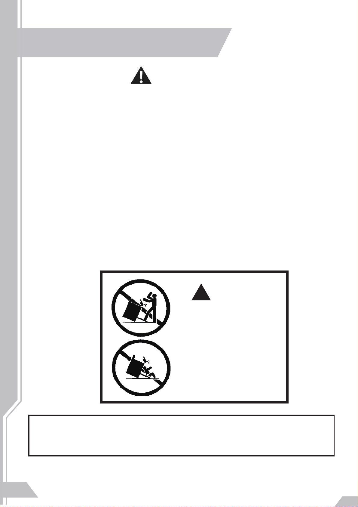
• A child or adult can tip the range and be killed. Re-engage
the anti-tip device if the range is moved . Do not operate
the range without the anti-tip device in place and engaged.
See installation instructions for details. Failure to do so can
result in death or serious burns to children or adults.
• This range must be secured and connected using the antitip device according to the installation instructions.
• Do not use the range if the anti-tip device has not been
properly installed and engaged.
• Failure to observe the information contained in the
installation instructions can lead to serious or fatal injuries for
children and adults.
ARNING
!
All ranges can tip
Injury to persons could result .
Install anti-tip devices packed
with range
See installation instructions
W
4
State of California Proposition 65 Warnings:
WARNING: This product contains one or more chemicals known to the State of California to cause cancer.
WARNING: This product contains one or more chemicals known to the State of California to cause birth defects or other
reproductive harm.
Page 6
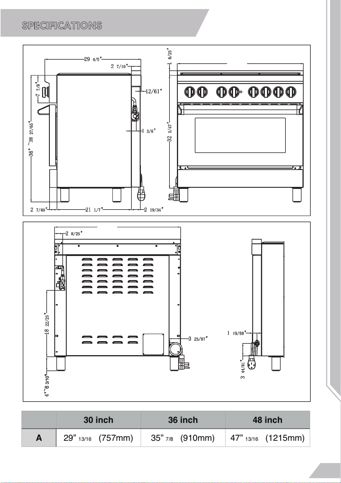
SPECIFICATIONS
A
A
5
Page 7
IMPORTANT SAFETY INSTRUCTIONS
ARNING
W
!
If the information in this manual is not followed exactly, a fire or
explosion may result causing property damage, personal
injury, or death.Dealer cannot be held liable for damage
occurring as a result of non-compliance with the instructions.
-Do not store or use gasoline or other flammable substances in
the vicinity of this or any other appliance.
-WHAT TO DO IF YOU SMELL GAS
•Do not light any appliance.
•Do not touch any electrical switch.
•Do not use any phone in your building.
•Immediately call your gas supplier from a neighbour's
phone. Follow the gas supplier's instructions.
•If you cannot reach your gas suppliers, call the fire department.
- Installation and service must be performed by a qualified
installer,
(In Massachusetts, installation must be performed by a
"Massachusetts" licensed plumber or gasfitter. A "T"
handle type manual gas valve must be installed in the gas
line connected to this appliance.)
- Theinstallationofappliance designed for manuafactured( mobile)
home installationmustconformwith the Manufactured Home
Construction and Safety Standard,Title 24CFR,Part 3280 I formerly
the Federal Standard for Mobile Home Construction and Safety,
Title 24,HUD(Part280) ] or with local codes where applicable..
service agency or the gas supplier.
6
– Note to the installer:
Please give these installation instructions to the consumer for the
local electrical/gas inspector.
Page 8
IMPORTANT SAFETY INSTRUCTIONS
When using the appliance, follow basic safety precautions,
including the following:
Read all instructions before installation and use of the range to
prevent accidents and machine damage.
W
ARNING
!
This appliance complies with current safety requirements.
Improper use of the appliance can lead to personal injury and
material damage.
Read all instructions before installing or using the oven for the
first time. Only use the appliance for its intended purpose.
Keep these operating instructions in a safe place and pass
them on to any future user.
The manufacturer reserves the right to make changes to its
products when considered necessary and useful, without
affecting the essential safety and operating characteristics.
This appliance has been designed for non-professional,
domestic use only.
Do not use this appliance to heat a room.
Do not place any pot or pan on the open oven door.
The door is made of glass and it can break if loaded with a
weight. Do not remove permanently affixed labels, warnings,
or plates from the product. This may void the warranty.
Please observe all local and national codes and ordinances.
Please ensure the range is properly grounded.
7
Page 9
IMPORTANT SAFETY INSTRUCTIONS
!
WARNING
Installation of any gas-fired equipment should be made by a
licensed plumber. A manual gas shut-off valve must be
installed in the gas supply line ahead of the oven in the gas
flow for safety and ease of service.
Make sure the appliance must be isolated from the gas
supply piping system and plug wire.
The plug should always be accessible.
Installation must conform with local codes or in the
absence of codes, the National Fuel Gas Code ANSIZ223.1/
NFPA54. Electrical installation must be in accordance with the
National Electrical Code ANSI/NFPA 70 - latest edition and/or
local codes.
IN CANADA: Installation must be in accordance with the current
CAN/CGA-fe 149.1 National Gas Installation Code or
CAN/CGA-B 149.2, Propane Installation Code and/or local codes.
Electrical installation must be in accordance with the current
CSA C22.1 Canadian Electrical Codes Part 1 and/or local codes.
This appliance shall not be installed with a ventilation system that
blow air downward toward the range/rangetop/cooktop; this type of
ventilation system may cause ignition and combustion problem with
the gas appliance resulting in a personal injury or unintended
operation
An air curtain or other overhead range/rangetop/cooktop hood, which
operates by blowing a downward airflow onto a
range/rangetop/cooktop, shall not be used/installedin conjunction
8
with this gas range.
Page 10

IMPORTANT SAFETY INSTRUCTIONS
Verify the type of gas being used at
the installation site . As shipped from
the factory , units are configured for
use with natural gas.
Make certain the range matches the
type of gas available at this location .
This range can be converted for use
with propane gas (LP ) and the
process is explained later in the manual.
For installation of the appliance at high
altitude , please consult your local gas
company for their recommen -dation
of the correct orifice sizes and any
other necessary adjustments that will
provide proper gas combustion at
specified altitudes.
CAUTION
When connecting unit to propane
gas , make certain the propane
gas tank is equipped with its own
high pressure regulator in addition
to the pressure regulator supplied
with the appliance. The pressure of
the gas supplied to the appliance
regulator must not exceed 14" (
37mb) water column.
• A manual
installed external to the appliance, in an
accessible location from the front, for the
purpose of shutting off the gas supply. The
supply line must not interfere with the back
of the unit. Make sure the gas supply is
turned off at the manual shut-off valve
before connecting the appliance.
• The range is supplied with its own pressure
regulator that has been permanently
mounted within the range body.
• The
• Always use pipe dope or Teflon® tape on
• Turn on gas and check supply line
gas supply connections should be made
by a competent technician and in accordance
with local codes or ordinances. In the
absence of a local code, the installation must
conform to the National Fuel Gas Code ANSI
Z223.1, Current Issue.
the pipe threads, and be careful not to apply
excessive pressure when tightening the
fittings.
connections for leaks using a soap solution
. Do not use a flame of any sort to check
for leaks.
gas shut-off valve must be
Natural Gas Requirements:
Supply Pressure: 6" to 14" water column. )
Propane Gas Requirements:
Supply Pressure: 11" to 14" water column.)
For Massachusetts Installations:
1.
Shut-off valve must be a “T” handle gas cock.
2.
Flexible gas connector must not be longer
than 36 inches.
3. Not approved for installation in a bedroom
or a bathroom unless unit is direct vent.
9
Page 11
IMPORTANT SAFETY INSTRUCTIONS
Do not carry or lift the range by the
W
!
ARNING
oven door handle or the control panel!
W
ARNING
!
Heating elements may be hot even though they are not
glowing. Interior surfaces of an oven become hot enough to
cause burns. External parts of the oven such as the door glass,
vents, and the control panel can become hot. During and after
use, do not touch, or let clothing or other flammable materials
come into contact with heating elements or interior surfaces of
the oven until they have had sufficient time to cool.
ARNING
W
!
Never pour cold water onto hot surfaces in a hot oven.The steam
10
created could cause serious burns or scalding and the sudden
change in temperature can damage the enamel in the oven
Page 12
IMPORTANT SAFETY INSTRUCTIONS
!
WARNING for Children
- As with any appliance, close supervision is necessary when the oven is
used by children.
- Do not leave children unattended: Children should not be alone or
unsupervised in the area where the appliance is installed. Do not allow
them to sit or stand on the appliance.
- As with any appliance, close supervision is necessary when used
by children.
- Children 8 years and older may only use the oven unsupervised if they
have been shown how to use it safely and recognize and understand the
consequences of incorrect operation.
- Children must not be allowed to clean or maintain the appliance
unsupervised.
- Children should not be left alone or unattended in an area where
an oven is in use. Never allow children to operate, sit or stand on any part of
the oven. Caution: Do not store items of interest to children in cabinets
above an oven. Children climbing on the oven to reach these items could
be injured.
- Danger of burns. The oven gets hot at the oven door glass, the vapor
handle and the operating controls. Children's skin is more sensitive to high
temperatures than that of adults.
Do not allow children to touch or play in, on or near the oven.
- Burn Hazard - Do not allow children to use the oven. Failure to do
so can result in severe burns or serious injury.
- Burn hazard!
Keep the spaces above and behind the range clear of any items that could
draw the attention of children . Otherwise , they can be tempted into climbing
onto the appliance.
- Danger of injury. Never allow children to hang or lean on any part of the
appliance
vent, the
11
Page 13
INSTALL GUIDE
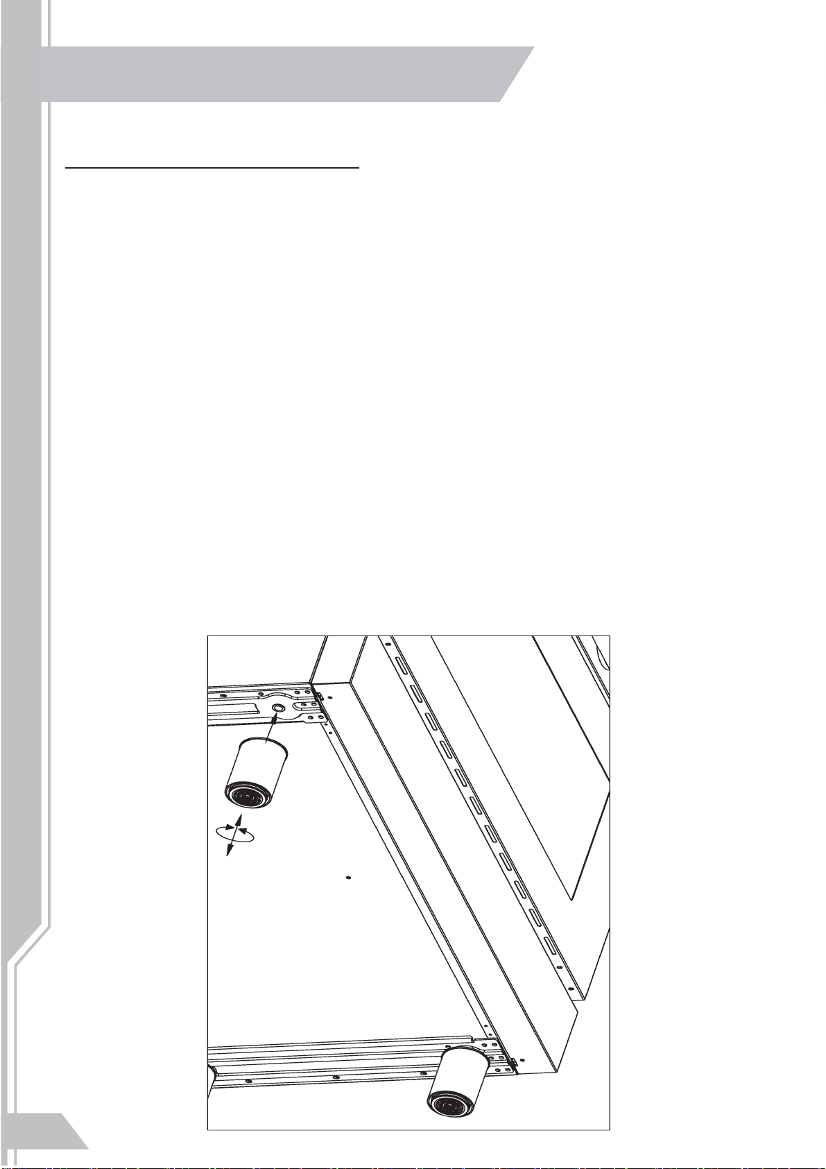
INSTALLING THE LEGS
The ranges must be used only with the legs properly installed. Four heightadjustable legs are shipped with the range in the polystyrene container
situated over the appliance. Before installing the legs, position the appliance
near its final location as the legs are not suitable for moving the appliance
over long distances. This next part requires 2 people. After unpacking the
range, tilt the range enough to insert the legs in the appropriate receptacles
situated on the lower part of the appliance. Lower the range gently to keep
any undue strain from legs and mounting hardware. If possible use a pallet or
lift jack instead of tilting the unit. Adjust leg height to the desired level by
twisting the inside portion of the leg assembly until the proper height is
reached. Check with a level that the cooktop is perfectly level.
12
Page 14
INSTALL GUIDE
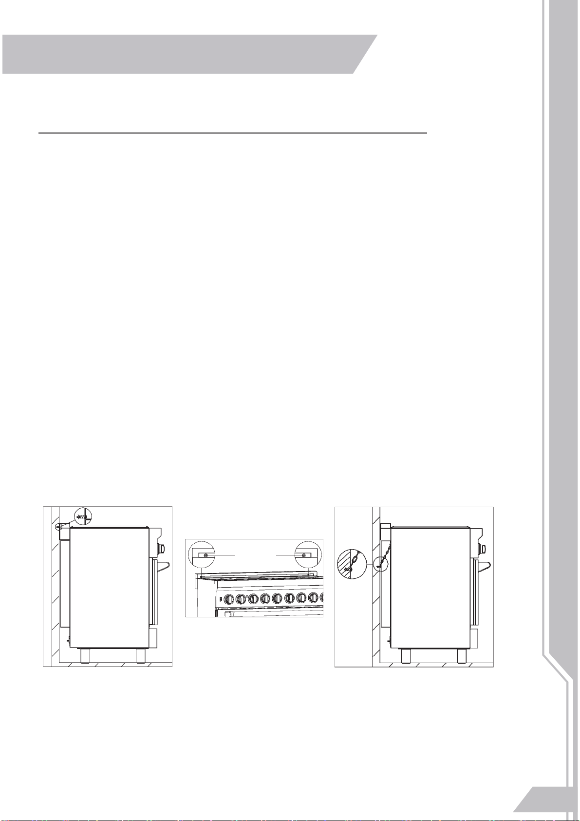
INSTALLING THE ANTI-TIP STABILITY DEVICE
The anti-tip bracket shipped with the range must be properly secured to
1)
the rear wall as shown in the picture below.The height of the bracket
from the floor must be determined after the range legs have been
adjusted to the desired height and after the range has been levelled.
Measure the distance from the floor to the bottom of the anti-tip bracket
receptacle on the back of the appliance.
Position the two anti-tip brackets on the wall at the desired height
plus 1/8" (0.32 cm). The brackets must be placed at 2 - 5/16" (6.0 cm)
from each side of the range. The distance between the two bracket
is 25 - 1/4" (64.1 cm). Secure the brackets to the wall with appropriate
hardware. Slide the range against the wall until the brackets are fully
inserted into their receptacles on the back of the range.
Check to see that the Anti-Tip device is installed properly. Grasp the top
rear edge of the range and carefully attempt to tilt it forward. Verify that
the Anti-Tip device is engaged.
2) Or, use the anti-tip chain, and tighten up with fixed screw on the wall,
and when the wall not suitable for installation, the chain shall be fixed to
the cabinet structure.
13
Page 15

INSTALL GUIDE
CABINETS
This range may be installed directly adjacent to existing countertop high
cabinets (36" or 91.5 cm from the floor).For the best look, the cooktop should be
level with the cabinet countertop. This can be accomplished by raising the unit
using the adjustment spindles on the legs.
ATTENTION: the range CANNOT be installed directly adjacent to kitchen
walls, tall cabinets, tall appliances , or other vertical surfaces above 36"(91.4
cm) high. The minimum side clearance in such cases is 6" (15.2 cm).Wall
cabinets with minimum side clearance must be installed 18" (45.7 cm) above
the countertop with countertop height between 35 1/2" (90.2 cm) and 37 1/2"
(94.6 cm). The maximum depth of wall cabinets above the range shall be 13"
(33.0 cm)
14
Page 16

INSTALL GUIDE
ELECTRICAL REQUIREMENTS
o reduce the risk of fire, electric shock, or personal injury:
T
WARNING
• Do not use an extension cord or adapter plug with this range.
• This range must be properly grounded.
• Check with a qualified electrician if you are in doubt as to whether your range
is properly grounded.
• Do not modify the plug provided with your range—if it doesn¡¯t fit the outlet,
have a proper outlet installed by a qualified electrician.
• All wiring and grounding must be done in accordance with local codes or, in
the absence of local codes, with the National Electrical Code, ANSI/NFPA No.
70 – Latest Revision (for the U.S.) or the Canadian Electrical Code CSA C22.1
– La est Revisions and local codes and ordinances.
• Wiring diagram is located on the back of the range. (Inside of the cover back
wire)
• This range is equipped with an electronic ignition system that will not operate
if plugged into an outlet that is not properly polarized.
• All gas models ar
e equipped with a power cord with an equipment-grounding
conductor and a grounding plug.
• A 120-Volt, 60-Hz, AC, approved electrical service with or 20-amp circuit
breaker or time-delay fuse is required for all U.S. and Canadian models.
• Do not reuse a power supply cord from an old range or other appliance.
• The power cord electric supply wiring must be retained at the range cabinet
with a suitable UL-listed strain relief.
• A time-delay fuse or circuit breaker is also recommended.
ounding
Gr
• All r
• All gas models have a power cord with an equipment-
anges must be grounded for personal safety.
grounding conductor
and a grounding plug.
• The plug must be firmly plugged into a three-prong outlet
that is properly installed and grounded in accordance with
all local codes and ordinances. In the event of a malfunction
or breakdown, grounding will increase the risk of electrical
shock by not providing a path for the electric current.
e proper
Ensur
ground
and firm
connection
before use.
15
Page 17

INSTALL GUIDE
• Do not use a damaged power plug or loose wall outlet.
• Do not use an extension cor
d or adapter with this appliance.
• Do not, under any circumstances, cut, modify, remove, or otherwise defeat
the grounding (third) prong from the power cord. If the plug and the outlet
do not match or you have any doubt, have a qualified electrician install the
proper outlet.
The customer should have the wall receptacle and circle checked by a
qualified electrician to make sure the receptacle is properly grounded.
Ground Fault Circuit Interrupters(GFCIs) are not required ot recommended for
gas range receptacles.
• NEVER connect ground wire to plastic plumbing lines, gas lines, or water
pipes.
Failure to follow these instructions can result in death, fire, or electrical
CAUTION
GAS
An agency-approved, properly-sized manual shut¬off valve should be
shock.
installed no higher than 3" (7.6 cm) above the floor and no less than
2" (5 cm) and no more than 8" (20.3 cm) from the right side (facing product).
To connect gas between shut-off valve and regulator, use agency-approved
, properly sized flexible or rigid pipe. Check all local code requirements.
EXHAUST HOOD INSTALLATION
This range will best perform when used with exhaust hoods. These hoods have
been designed to work in conjunction with the range and have the same finish
for a perfect look. For maximum performance, the height of the bottom of the
hood from the cooktop should be between 30" (76.2 cm) and 36" (91.4 cm).
This would typically result in the bottom of the hood being 61 1/2" (156.2 cm)
to 67 1/2" (171.5 cm) above the floor. These measurements provide for safe
and efficient operation of the hood. Before installation of the exhaust hood,
consult local or regional building and installation codes for additional specific
clearance requirements. Refer to the range hood installation instructions
provided by the manufacturer for additional information.
16
Page 18

INSTALL GUIDE
WIRING DIAGRAM
36 INCH MODEL
CAUTION
Label all wires prior to disconnecting when servicing controls. Wiring
errors can cause improper and dangerous operation. Verify proper
operation after servicing
17
Page 19

INSTALL GUIDE
WIRING DIAGRAM
18
30 INCH MODEL
CAUTION
Label all wires prior to disconnecting when servicing controls.
Wiring errors can cause improper and dangerous operation. Verify
proper operation after servicing
Page 20

INSTALL GUIDE
GAS CONNECTION
All gas connections must comply with national and local codes. The gas supply
line (service) must be the same size or greater than the inlet line of the
appliance. This range uses a 1/2" NPT inlet
(see drawing below for details of gas connection). On all pipe joints use
appropriate sealant resistant to gas.
This range can be used with Natural or LP/Propane gas. The range is
shipped from the factory for use with natural gas.
For LP/propane household installation, the appliance must be converted by a
licensed installer, qualified licensed plumber, or gas service company. Gas
conversion is important for safe and effective use of the appliance. It is the
responsibility of the consumer and his/ her installer of the range to perform the
appropriate gas conversion following the directions of this manual
THE GAS CONVERSION PROCEDURE IS DESCRIBED
IN THIS MANUAL. THE GAS CONVERSION KIT MUST
BE PURCHASED SEPARATELY.
Please provide the service person with this manual before work is started
on the range.
DO NOT USE AN OPEN FLAME WHEN
!
!
Leak testing of the appliance shall be conducted according to the
manufacturer's instructions. Before placing the oven into operation, always
check for leaks with soapy water solution or other acceptable method. Check
for gas leakage with soapy water solution or other acceptable methods in all
gas connections installed between inlet gas pipe of the appliance, gas
WARNING
CHECKING FOR LEAKS!
regulator, and the manual shut-off valve.
19
Page 21

INSTALL GUIDE
MANUAL SHUT-OFF VALVE
THIS VALVE IS NOT SHIPPED WITH THE APPLIANCE AND MUST BE
SUPPLIED BY THE INSTALLER.
The manual shut-off valve must be installed in the gas service line between the
gas hook-up on the wall and the appliance inlet, in a position where it can be
reached quickly in the event of an emergency.
In Massachusetts: A T handle type manual gas valve must be installed in the
gas supply line to this appliance.
FLEXIBLE CONNECTIONS
In case of installation with flexible couplings and /or quick - disconnect fittings
, the installer must use a heavy-duty, AGA design-certified commercial
flexible connector of at least 1/2" (1.3 cm) ID NPT
(with suitable strain reliefs) in compliance with ANSI Z21.41 and Z21.69
standards.
In Massachusetts: The unit must be installed with a 36" (3-foot) long flexible gas
connector.
In Canada: use CAN 1-6.10-88 metal connectors for gas appliances and CAN 1-6.
9 M79 quick disconnect device for use with gas fuel.
PRESSURE TEST-POINT STOPPER VALVE
To avoid gas leaks, the pressure test-point stopper valve and gasket supplied
with the range must be installed on the gas fitting at the back of the range
according to the diagram below
20
Page 22

INSTALL GUIDE
PRESSURE REGULATOR
Since service pressure may fluctuate with local demand, every gas
cooking appliance must be equipped with a pressure regulator on
the incoming service line for safe and efficient operation.
The pressure regulator shipped with the appliance has two female
threads 3/4" NPT. The regulator shall be installed properly in order to be
accessible when the appliance is installed in its final position.
PRESSURE REGULATOR
Manifold pressure should be checked with a manometer and
comply with the values indicated below:
Natural gas -> 4. 0" W.c.P.
LP/Propane -> 10.0" W.c.P.
Incoming line pressure upstream from the regulator must be 1" W.c.P.
higher than the manifold pressure in order to check the regulator. The
regulator used on this range can withstand a maximum input pressure
of 1/2 PSI (13.8" w.c. or 3.5 kPa) If the line pressure exceeds tha
amount, a step-down regulator is required .
The appliance, its individual shut-off valve, and the pressure
regulator must be disconnected from the gas line during any
pressure testing of that system at pressures in excess of 1/2 PSI
(13 .8" w.c. or 3.5 kPa). The individual manual shut-off valve must be
in the OFF position during any pressure testing of the gas supply
piping system at test pressures equal to or less than 1/2 PSI (13.8"
w.c . or 3.5 kPa)..
21
Page 23

INSTALL GUIDE
APPLIANCE SERVICING
Before carrying any servicing operation disconnect the
appliance from gas and electric supply and extra appliance
from final installation place in order to have access to the
appliance for proper servicing intervention.
GAS CONVERSION
WARNING: Before carrying out this operation, disconnect
the appliance from gas and electricity.
Gas conversion shall be conducted by a licensed and
certified professional.
The gas conversion procedure for this range includes 3
steps:
1.
Pressure regulator configuration
2.
Burner nozzle replacement
3.
Minimum flame adjustment
The conversion is not completed if all 3 steps have not
been concluded properly.
IMPORTANT: Each nozzle has a number indicating its flow
diameter printed on the body. Consult the table on step 2
for matching nozzles to burners.
Save the original nozzles removed from the range for future
use.
22
Page 24

INSTALL GUIDE
STEP 1: PRESSURE REGULATOR CONFIGURATION
The pressure regulator supplied with the appliance is a
convertible type pressure regulator for use with Natural
Gas at a nominal outlet pressure of 4" w.c. or LP gas at a
nominal outlet pressure of 10" w.c. and it is pre-arranged
from the factory to operate with Natural Gas. It can be
converted for use with propane gas by following these
steps:
a. Unscrew by hand the upper metal cap of the regulator.
b. Unscrew by hand the silver plastic piece screwed under
the above mentioned metal cap. The silver plastic piece
has arrows indicating the position for natural gas (NAT)
and LP gas (LP). Reverse its direction and screw it back
firmly against the cap.
c. Screw by hand the metal cap in the original position on
the regulator.
STEP 1a
STEP 1b
STEP 1c
23
Page 25

INSTALL GUIDE
STEP 2: BURNER NOZZLE REPLACEMENT
To replace the nozzles of the surface burners : lift up the
burners and unscrew the nozzles shipped with the range
using a 7 mm (socket wrench). Replace nozzles using the
conversion set. Each nozzle has a number indicating its flow
diameter printed on the body. Consult below figures for
matching nozzles to burners :
LP:
0.65
NG: 1.04
LP: 0.95
NG: 1.55
LP: 1.08
NG: 1.79
LP: 0.95
NG: 1.55
LP: 0.65
NG: 1.04
LP: 1.27
NG: 2.30
3
LP: 1.08
NG: 1.79
0”
LP: 1.27
NG: 2.30
Bottom Bake Burner: NG: 2.38 / LP: 1.27
Top Broiler Burner: NG: 1.79 / LP: 1.08
LP: 0.95
NG: 1.55
36”
LP: 1.08
NG: 1.79
24
Page 26

INSTALL GUIDE
STEP 3: MINIMUM FLAME ADJUSTMENT
These adjustments should be made only for use of the
appliance with natural gas. For use with liquid propane gas, the
choke screw must be fully turned in a clockwise direction.
Light one burner at a time and set the knob to the MINIMUM
a.
position (small flame).
Remove the knob.
b.
The range is equipped with a safety valve. Using a small-
c.
size slotted screwdriver, locate the choke valve on the valve
body and turn the choke screw to the right or left until the
burner flame is adjusted to desired minimum.
Make sure that the flame does not go out when switching
d.
quickly from the MAXIMUM to the MINIMUM position when
knob is re-installed.
25
Page 27

INSTALL GUIDE
PLACEMENT OF COOKTOP BURNERS AND GRATES
CAUTION
1.
Do not operat
Position surface burner heads on top of the surface burner
e the surface burners without all burner parts in place.
bases as shown at right. The electrodes will fit into the slot in
the bottom of the heads. Make sure the surface burner heads
are flat and parallel with the cooktop.
2.
Place the matching size caps on top of each surface burner
head.
3.
CA
UTION
Always keep the burner caps and burner heads in place whenever the
surface burners are in use. Do not allow spills, food, cleaning
agents or any other material to enter the gas orifice holder
openings.
Place the left, center, and right surface burner grates on the
cooktop. The edges of the grates should match up with the porcelain
edges of the cooktop.
To prevent flare-ups and avoid creation of harmful by-products, do not
use the cooktop without all burner caps properly installed to insure proper
ignition and gas flame size.
Check and be sure the size of each burner cap matches the size of the
burner head. Check and be sure that all round style burner caps are
correctly in place on round burner heads.
Burner cap
Burner cap lip
Correct burner cap placement
26
Incorrect burner cap placement
Page 28

INSTALL GUIDE
INSTALLATION Checklist
1. Is the range mounted on its legs?
2. Is the back guard securely connected?
3. Has the anti-tip device been properly installed?
4.
Does the clearance from the side cabinets comply with the manufacturers
directions?
5. Is the electricity properly grounded?
6.
Is the gas service line connected following the directions of the manufacturer?
7.
Have all the proper valves, stoppers and gasket been installed between the
range and the service line?
8. Has the gas connection been checked for leaks?
9.
Has the range been set for the type of gas available in the household?
10. Does the flame appear sharp blue, with no yellow tipping,
shooting or flame lifting?
11. Has the minimum setting for all burners been adjusted?
12. Have you recorded the model # and serial # of your unit incase of need
for service? (Located on box label or back of the unit)
WARNING
!
USING THE OVEN FOR THE FIRST TIME
We recommend that before you cook in your new cooker you heat the oven to 380°F for
2hrs to run in BAKE mode. This is to burn off the residue from production. Please make
sure to open all windows and doors in the kitchen during this time to allow for proper
ventilation. After the oven cools wipe it out with hot water and a mild detergent. We also
recommend cleaning the racks and shelves before use.
When using the cooker for the first time you may notice the following......
There may be a smell. This is quite normal when the cooker is first heated as residual
oil from production of parts will be burnt off quickly.
There may be noises. This is also quite normal as new parts move and settle into place
during the initial heating process.
27
Page 29

USE GUIDE
This product is intended for the cooking of food and must not be used for other
purposes.
Unstable or deformed pans should not be placed on the burners or hot plates in
order to avoid accidents caused by spill over. Particular care should be taken
when cooking with oil or fat.
Always ensure that the knobs are in the "O", Off, or Stop position when the
appliance is not in use.
Before maintenance and cleaning, disconnect the appliance and allow cooling
down. For reasons of hygiene and safety this appliance must always be kept
clean.
Take care when using cleaning products in spray form. Never direct the spray
onto the electrical wiring, thermostat and bulb
When placing food in the oven, or when removing a large quantity of oil, juice,
etc., any spills onto the bottom of the oven must be cleaned before starting to
cook to avoid unpleasant smoke and also the possibility of these substances
catching fire.
Ensure that air can circulate around the gas appliance. Poor ventilation can
result in lack of oxygen and extinguish the flame.
The use of a gas cooking appliance produces heat and humidity in the room
where it is installed.
Ensure good ventilation of the room, keep adequate natural ventilation or
install an extractor hood with a discharge tube.
Supply the appliance with the type of gas stamped on the relevant label
situated in the immediate vicinity of the gas connection tube.
Ensure that the oven grids are inserted correctly. (See instruction as below.)
28
Page 30

USE GUIDE
NEVER cover any slots, holes or passages in the oven
bottom or cover an entire rack with materials such as aluminum
foil. Doing so blocks air flow through the oven and may cause
carbon monoxide poisoning. Aluminum foil linings may also trap
heat, causing a fire hazard.
NEVER use this appliance as a space heater to heat or warm
the room. Doing so may result in carbon monoxide poisoning
and overheating of the oven.
USING THE COOKTOP BURNERS
The knobs for the gas burners of the cooker are found on the
control panel. There are indication marks on each knob to
indicate the necessary knob positions for maximum (MAX) and
minimum (MIN) flame settings.
TO LIGHT A BURNER
1. Push and hold the knob corresponding to the burner and turn it
counter-clockwise to MAX.
2. Hold it for 3 to 5 seconds. The ignition will spark, gases will
flow, and the burner will ignite. The burner is at its maximum
size.
You can reduce the flame size by turning the knob counter
- clockwise to your desired setting.
If the burner fails to light, turn the knob to its OFF position and
repeat steps 1-2.
The burner flame should be blue.
NOTE : On first use, it will be required to hold onto
the knob at MAX position for 20-30 seconds to
allow the gases to completely fill the operating
system's inner piping.
29
Page 31

3. Check that the flame is regular.
If you suspect that the flame is irregular, ensure burner
caps are installed correctly (See instructions below.)
Burner cap
Burner cap lip
Correct burner cap placement
Incorrect burner cap placement
TIPS FOR USING PANS CORRECTLY
ATTENTION!
Always ensure that bottom and handles of pans do not protrude
from the worktop. When cooking with flammable fat such as oil, do
not leave the range unattended. Use pots of the appropriate size
on each burner following the indication of the diagram below.
Recommended pan size inches (mm)
Burner
Auxiliary
Semi Rapid
Rapid
3"- 5-1/2" (90 -140)
5 -1/2" -10- 1/4" (140 - 260)
7- 1/8" -10- 1/4" (180-260)
8 - 2/3"-10 - 1/4" (220 - 260)
Dual burner
30
Page 32

USE GUIDE
WHEN BOILING LIQUIDS:
Turn the knob to the MINIMUM position once boiling is
reached to avoid overflow. Always use pots with matching
lid. Dry the bottom of pans beforoperation. Use pots with
a flat, thick bottom (except for wok cooking).
WOK COOKING:
Always use the wok adapter supplied with the range. Wok
pan external diameter shall not be smaller than 10" (25cm)
and larger than 16" (40cm). SIMMERING: use the simmer
ring supplied with the range.
31
Page 33

USE GUIDE
USING THE GAS OVEN
Our oven functions allow the user to have flexibility in the
method of cooking and provide heating alternatives to
suit a wide variety of dishes.
HEATING
INDICATOR
TIMER
TEMPERATURE SETTING
LIGHT
To PRE-HEAT:
Set TIMER to ON. Set TEMPERATURE SETTING knob to desired preheat temperature. Heating Indicator Light will stay lit until oven has
reached set pre-heat temperature. Oven flame may turn on and off to
maintain set temperature until either knob is set to OFF.
BAKE
Heat comes from bottom heating elements. Suitable for cakes, muffins,
pizzas,and delicate egg dishes.
To use:
32
Turn the temperature setting knob to desired bake temperature. If bake
time is required, set the timer to desired baking duration. Oven will stop
heating once time expires. Otherwise, if TIMER is in ON position, oven
will heat until temperature setting knob is turned to OFF.
Page 34

USE GUIDE
CONVECTION BAKE
Heat comes from bottom elements combined with convection fan
air circulation for faster, more even, cooking. Suitable for dish
temperature from 0 to 500°F.
To use:
Turn the temperature setting knob to desired bake temperature.
Turn the Convection Fan switch on. If bake time is required, set
the timer to desired baking duration. Oven will stop heating once
time expires. Otherwise, if TIMER is in ON position, oven will
heat until temperature setting knob is turned to OFF. Once timer
reaches end time, the oven will stop heating.
BROIL
Heat comes from top grill elements which direct radiant heat
onto the food. Used for grilling or browning meats.
To use:
Turn the temperature setting knob to BROIL. If broil time is
required, set the timer to desired baking duration. Oven will stop
heating once time expires. Otherwise, if TIMER is in ON position,
oven will heat until temperature setting knob is turned to OFF.
CONVECTION BROIL
Heat comes from top grill elements which direct radiant heat onto
the food. Used for delicately grilling or browning meats, particularly
thinner meats.
To use:
Turn the temperature setting knob to BROIL. Turn the Convection
Fan switch on. If broil time is required, set the timer to desired
baking duration. Oven will stop heating once time expires.
Otherwise, if TIMER is in ON position, oven will heat until
temperature setting knob is turned to OFF.
33
Page 35

USE GUIDE
USING THE OVEN LIGHT
The light can be switced on/off using the switch on the left
side of the control panel.
COOKING TIMES
Cooking times can vary according to the type of food, its
density and its size.
34
Page 36

USE GUIDE
35
Page 37

CARE GUIDE
REPLACING THE OVEN LIGHT BULBS
WARNING!
Disconnect power before servicing unit.
To replace the oven light bulb, unscrew the protection glass
cover that projects out inside the oven.
NOTE: Touching the bulb with fingers may cause
burns to the skin. Always use protective glove or use
a cloth to remove the bulb.
CLEANING YOUR RANGE
ATTENTION!
During cleaning operation never move the appliance from its
foreseen original installation position.
ATTENTION!
Never use abrasive cleaners!
Scratches on the stainless steel surfaces are permanent.
Do not clean the range when it is hot!
Cleaning after installation: use a stainless steel cleaning
product or wipe to eliminate the residues of the
protection film after removal.
36
Page 38

CARE GUIDE
Cleaning the cooktop: periodically clean the burner heads, the
cast iron pan supports and the burner caps using warm water.
Remove burned food and fat residues with a rubber spatula .
If food residue prevent the smooth operation
knobs, call the customer service hotline to schedule service by a
factory-trained professional.
Cleaning stainless steel: for best results use a stainless steel
cleaner product with a soft sponge or wipe. Alternatively use a
soft sponge or cloth with a warm soap and water solution.
Never use abrasive powders or liquids!
Cleaning the burner caps: lift the burner caps from the burner
heads and wash them in a warm soap and water solution. Dry
thoroughly before using them again. Before reinstalling them
on the burner head, check that the gas flow holes are not
clogged with food residues or cleaning product residues.
Cleaning Enamel: enamelled parts should be cleaned
frequently with warm soap and water solution applied with
soft sponge or wipe. Never use abrasive powders or liquids!
of the
control
a
Do not leave acid or alkaline substances on the enamelled
parts (such as vinegar, lemon juice, salt, tomato sauce, etc.).
Use a rubber spatula to remove fat residues.
Cleaning glass door: clean the glass using a non- abrasive
sponge or wipe with a warm soap and warm water solution.
Use a rubber spatula to remove fat residues.
ATTENTION: while cleaning the door, avoid spillage of food
residues and cleaning products in the venting holes situated
on the top side of the door. To clean the inside of the oven
door, call a professional.
37
Page 39

TROUBLESHOOTING GUIDE
Baking Pr
Food br
Food too brown on bottom
Food is dry or has shrunk
excessively
Food is baking or roasting too
slowly
owns unevenly
oblem Cause
Oven no
•
Aluminum f
•
Baking utensil t
•
Pans t
•
Oven no
•
Using glass
•
Incorrect rack position
•
Pans t
•
Oven temper
•
Baking time t
•
Oven door opened fr
•
Pan si
•
Oven temper
•
Oven no
•
t preheated
oil on oven rack or oven bottom
ouching each other or oven walls
t preheated
, dull or darkened metal pans
ouching each other or oven walls
ature too high
oo long
ze too large
ature too low
t preheated
oo large for recipe
equently
Pie crusts do not brown on
bottom or crust is soggy
Cakes pale, at and may not be
done inside
Cak
es high in middle with crack
on top
Oven door opened fr
•
T
ightly sealed with aluminum foil
•
Pan si
•
Baking time no
•
Using shin
•
Inc
•
Oven temper
•
Oven temper
•
Inc
•
Cak
•
Oven door opened t
•
Pan si
•
Oven temper
•
Baking time t
•
Pans t
•
ze too small
t long enough
y steel pans
orrect rack position
ature is too low
ature too low
orrect baking time
e tested too soon
ze may be too large
ature too high
oo long
ouching each other or oven walls
equently
oo often
38
Pie crust edges too brown
Inc
•
•
•
•
orrect rack position
Pan si
Oven temper
E
ze too small
dges of crust too thin
ature too high
Page 40

TROUBLESHOOTING GUIDE
PROBLEM
Burner will
not ignite
Burner
will not
operate
Gases not
flowing.
Burner
Flames are
uneven,
yellow and/
or noisy
POSSIBLE CAUSE SOLUTION
There is no power to
the cooktop
First time use. Air
still in the gas line.
Control knob is not
set correctly.
The burner port is
clogged.
Improper
installation.
Burner port(s) are
clogged.
Burner caps are not
positioned properly.
Propane gas is being
used.
Plug into a grounded 3 prong outlet. Replace
fuse or reset circuit breaker.
Turn on any one of the surface burner knobs
to release air from the gas lines.
Push in knob before turning to a setting.
Clean burner port opening using a sti, nylon
toothbrush or a straightened paper clip.
Turn the manual gas shut-off valve on.
Installer should make sure regulator is
correctly oriented (arrow towards unit).
Clean burner port opening using a sti, nylon
toothbrush or a straightened paper clip.
Place burner caps so that the alignment pins
are properly aligned with the slots.
The range should be converted to LP gas by
a qualied technician.
Burner
ame is too
high or too
low
Burner
makes
popping
noises
Excessive
heat
around
cookware
on cooktop
Cooktop gas supply
is not correct.
The gas pressure is
not correct.
The burner is wet. Allow the burner to dry before using.
The burner cap and/
or gas spreader
is not positioned
correctly.
The cookware is not
the proper size for
the burner.
Ensure the range is set for the correct
gas type. It is factory set for natural gas. If
connected to LP gas the burners should be
converted to LP gas with the orice/injector
kit supplied and the pressure regulator
converted to the LP gas setting by a qualied
technician.
Make sure the pressure regulator is installed
correctly and the gas line pressure is correct.
See Installation Instructions.
Place burner caps so that the alignment pins
are properly aligned with the slots.
Use cookware with a bottom surface
approximately the same size as the cooking
area and burner. Cookware should not
extend more than 1” (2.5 cm) outside the
cooking area. Adjust the ame so that it
does not come up around the cookware.
39
Page 41

TROUBLESHOOTING GUIDE
OBLEM POSSIBLE CAUSE SOLUTION
PR
Oven is not
heating
Oven is not
ooking evenly
c
Broil does
not work.
ooling fan
C
continues to
run after oven
is turned o
Oven light is
not working
properly
Oven light
stays on
No power to the
oven
Oven control not
turned on
Not using the correct
bake ware or oven
rack position
Knob settings are not
in the correct
positions.
The electronic
components have
not yet cooled
suciently
Light bulb loose or
burned-out.
Door is not closing
completely
Reset the circuit breaker or replace the
fuse in the electrical box to your oven.
Make sure the oven temperature has
been selected and timer is not "OFF".
Refer to cook charts for recommended
rack position. Always reduce recipe
temperature by 25 °F (15 °C) when
baking with Convention Bake mode.
Make sure oven temperature
selection knob is set to " BROIL" and
timer is not set to "OFF"
The fan will turn o automatically
when the electronic components have
cooled suciently.
Reinsert or replace the light bulb.
Touching the bulb with ngers may
cause the bulb to burn out.
Check for obstruction in oven door.
Check to see if hinge is bent or door
switch broken.
Cannot remove
lens cover
Heat blowing out
from the front
of oven.
essive
Exc
Moisture
Porcelain Chips
Soil build-up around
the lens cover.
Oven cavity
ventilation on
Porcelain interior
is bumped by oven
racks
Wipe lens cover area with a clean, dry
towel prior to attempting to remove
the lens cover.
The oven cavity ventilation is
operating until the oven is sufficiently
cooled. This is normal.
When using bake mode, preheat
the oven rst. Convection Bake and
Convection Roast will eliminate any
moisture in the oven.
When removing and replacing oven
racks, always tilt racks upward and do
not force them to avoid chipping the
porcelain.
FOR MORE HELP, VISIT OR CALL THE CUSTOMER
SUPPORT LINE AT 1-888-784-3108.
40
Page 42

WARR
ANTY AND SERVICE
TO RECEIVE W
BE REGISTERED. TO REGISTER, VISIT:
WWW.COSMOAPPLIANCES.COM/WARRANTY
FOR FULL WARRANTY DETAILS ON THIS PRODUCT PLEASE VISIT :
WWW.COSMOAPPLIANCES.COM/WARRANTY
ARRANTY SERVICE, YOUR PRODUCT MUST
WWW.COSMOAPPLIANCES.COM
Page 43

Page 44

 Loading...