

Page 1

Installation Guide
& User's Manual
WALL MOUNT
RANGE HOOD
COS-63175
COS-63190
COS-63175S
COS-63190S
COS-668A750
COS-668A900
COS-668AS750
COS-668AS900
COS-668WRC75
COS-668WRC90
COS-668WRCS75
COS-668WRCS90
This manual is made with 100 % recycled paper.
Electronic version of this manual is available at:
www.cosmoappliances.com
Page 2

1
Page 3

SEE PAGE 13 FOR INSTRUCTIONS ON INSTALLING FILTERS
2
Page 4

3
burned.
Always leave safety grills and filters in place. Without these
components, operating blowers could catch onto hair, fingers and loose
clothing. The manufacturer declines all responsibility in the event of failure to
observe the instructions given here for installation, maintenance and suitable
use of the product. The manufacturer further declines all responsibility for
injury due to negligence and the warranty of the unit automatically expires
due to improper maintenance.
Page 5

SAFETY INSTRUCTIONS _______________________________________ 3
PARTS DIAGRAM ___________________________________________ 5-6
INSTALLATION REQUIREMENTS ________________________________ 7
PARTS LIST _________________________________________________ 8
RANGE HOOD INSTALLATION _______________________________ 9-11
BAFFLE FILTER INSTALLATION ________________________________ 12
DUCTLESS CONVERSION FILTERS _____________________________ 13
INSTALLING THE OIL CUP _____________________________________ 14
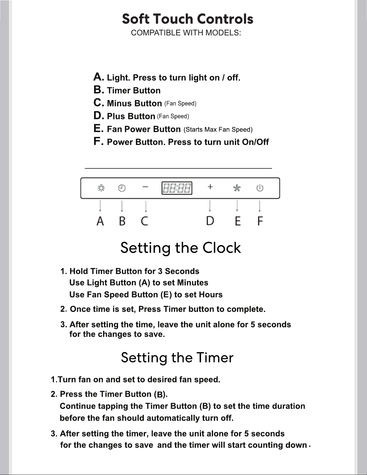
PUSH BUTTON CONTROLS_____________________________________ 15
SOFT TOUCH CONTROLS ___________________________________ 16
MAINTENANCE ______________________________________________ 17
TROUBLESHOOTING _________________________________________ 18
WARRANTY & SERVICE _______________________________________ 19
4
Page 6

12.8"
11.1"
(Units with Glass Visor)
21.5"-39.2"
18.5"
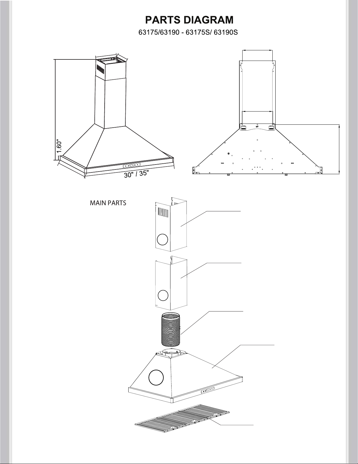
1. Top Chimney (Inner Chimney)
2. Bottom Chimney (Outer Chimney)
7"
A
12.5"
7"
13.6"
5
B
3. Exhaust Pipe
4. Core Unit
5. Tempered Glass
C
6. Grease Filters
Page 7
25.6"-39.4"
19.75"
8.25"
6.75"
6.81"
6.89"
11.18"
1. Top Chimney (Inner Chimney)
C
A
2. Bottom Chimney (Outer Chimney)
B
3. Exhaust Pipe
4. Core Unit
5. Grease Filters
6
Page 8
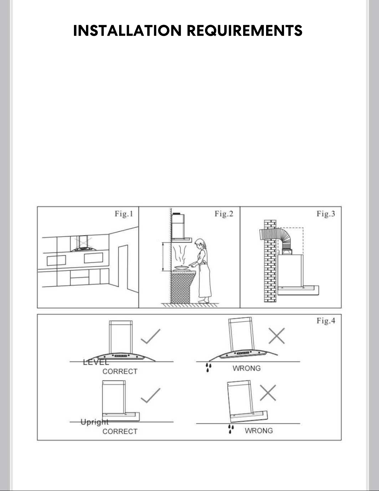
1. Do not install the range hood near open doors and windows to avoid reduced
performance. (Fig.1)
2. Install the range hood directly above the cooktop. The optimal distance between the
cooktop and lower edge of the range hood is 24" to 36". (Fig.2) Install at the height
appropriate to your ceiling. Make sure the chimney reaches the ceiling. If your ceiling
leaves the hood a few inches higher or lower than 24" to 36" you can still install it without a
major loss of performance.
3. For optimal performance, do not over extend the exhaust tube and avoid unnecessary
bending. (Fig.3)
4. After hanging the unit on the wall, ensure the range hood is straight and leveled. (Fig.4)
5. The air outlet must be connected to chimney flumes or combustion gas ducts. Under no
circumstances should the air outlet be connected to ventilation ducts for rooms in which
fuel-burning appliances are installed.
24"-36"
7
Page 9

(outer chimney)
E.
(inner chimney)
H.
11 pcs 2/8" x 1 3/8" Plastic Anchors
A.
B. 11 pcs 1/8" x 1 7/8" Screws (48mm)
C. 4 pcs 1/8" x 3/8" Screws (35mm)
D. Core Unit Bracket (Main Body)
E. Outer Chimney Cover Bracket
F. 6 in. Round Aluminum Duct
G. Oil Cup
H. Inner Chimney Cover Bracket
G
Note: Hardware, number of screws, anchors and
accessories will vary based on product model.
8
Page 10

WALL MOUNT RANGE HOOD INSTALLATION
Preparing Your Wall / Mounting Instructions
Place the range hood on the wall and mark the
position where you want to install.
A height of 24" to 36" from the cooktop is
recommended for optimal
atthe height appropriate for your ceiling.
performance. Install
You
mayinstall higher if needed. Make sure the
chimney can still reach the ceiling. If your
ceiling leaves thehood a few inches higher or
lower than 24" to 36"you can still install it withouta major loss of performance.
There are 3 included brackets.
Start your measurements from the top down to
make sure the chimney reaches the ceiling with
no gap if desired.
* If you intend to run your ducting through the back wall behind
the hood, it is not necessary for the chimney to touch the ceiling.
A. Find the Core Unit Bracket (D) that will hold
the back of the range hood. Mark the
locations on the wall with a pencil or marker.
B. Drill a 5/16" (8mm) hole at each marked
location.
C. Insert wall anchors into each hole, gently
tapping in place.
Take the Core Unit Bracket ( Part D) that
D.
will hold the range hood and firmly tighten with
3 wood screws (Part B) into the anchors.
Secure range hood by hanging on bracket.
H
WALL
Wood Screw
Mounting Bracket
D
(Inner Chimney)
E
(Outer Chimney)
7"
Core Body
13.6"
9
Page 11
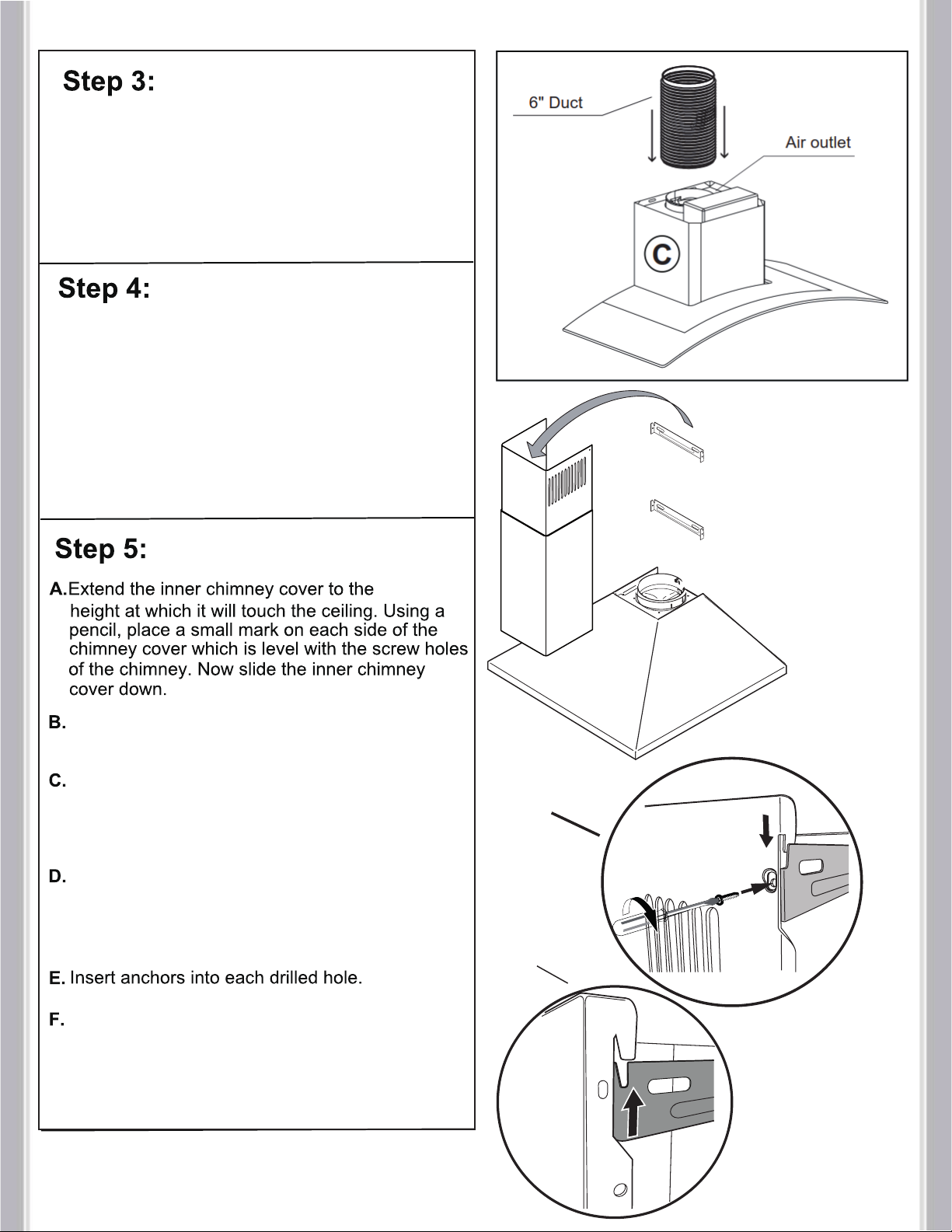
Locate the 6" round aluminum duct (F) and
attach it to the top air outlet on the main body
of the range hood with HVAC foil tape
(not included). Make sure it is connected
tightly.
Place the bottom of Outer Chimney into Core
Body's seating located near vent hole.
Then Insert the Inner Chimney cover into the
Outer Chimney Cover.
Note that the Inner Chimney cover must slide
into the Outer Chimney cover's orientation slot.
(see step 7 for mounting bracket install)
A
B
Using a pencil, place a small mark on the wall
on each side of the chimney
Align the middle of the Inner chimney
bracket (H) with the drawn line and make
a mark where each screw hole in your
wall will need to be drilled for mounting of
the bracket.
Drill 1/4" holes at each marked location
The drilled hole should be slightly smaller
than the diameter of the anchor.
Align Inner chimney bracket (H) with the
drilled holes and firmly screw it into place.
Use 3/8"
screws
(parts list C)
A
B
* (Step 7)
10
Page 12

Extend the 6" Duct to the vent pipe of your
building or outside. For optimal performance
try to minimize bending of the duct.
Mount outer chimney bracket (E) to the wall
appropriate to the height of the outer
chimney. Use the hooks on bracket to
mount bottom chimney.
Extend Inner Chimney until it touches the
ceiling. Align sides with Inner Chimney
Mounting Bracket (H)(already mounted to
wall) and firmly screw sides of Inner
Chimney to bracket with 3/8" screws (C
in parts list).
WALL
* If you intend to run your ducting through the back
wall behind the hood, it is not necessary for the
chimney to touch the ceiling.
Insert and install filters according to the
diagram on Next Page.
Start at 90°Angle and line up the hooks
on filter with the rectangular slots on the
range hood. Lift the filter up and push the
button on filters to allow it to lock into
place.
11
Page 13

Press Button in and down
12
Page 14

Press the center of the filter firmly. While pressing firmly twist and lock into place.
(see instructions)
Charcoal Filter Model # : CFK1-TM
13
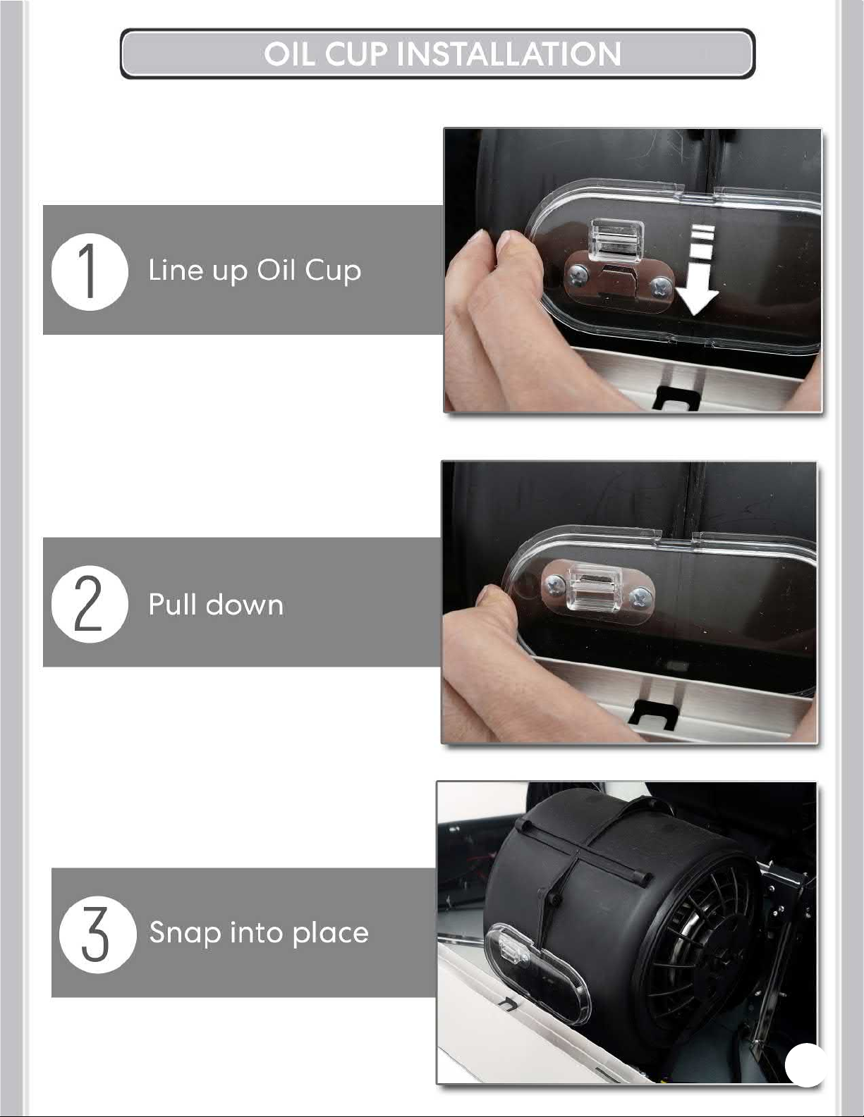
See NEXT PAGE for Oil Cup installation instructions
Page 15
14
Page 16

15
Page 17
COS-668WRCS75, COS-668WRCS90
COS-668AS750, COS-668AS900
COS-63175S , COS-63190S
Note: When Fan is ON + or - will increase or decrease fan speed.
16
Page 18
17
Page 19

My range hood is noisy
A. Check inside the range hood for any
loose debris and remove.
If your range hood is still noisy after checking,
please call 1-888-784-3108.
My range hood has
poor performance
My range hood shakes
A. The range hood and cooktop are too
far away from each other.
Optimal distance is 24" to 36"
B. There are too many open windows or
doors in the area. Close some doors or
windows.
C. The motor performance has decreased
due to wear. Replace motor.
D. Check and make sure the tape holding
down the damper flaps at the vent hole
are removed before use.
E. The oil cup is full and needs to be
cleaned out.
F. The filters are clogged and need to be
cleaned.
A. The installation is not secure. Check
again and make sure the installation
hardware is securely mounted.
B. The fan is broken or not balanced.
Re-align or replace fan.
C. The motor is loose. Check and make
sure the motor is solidly mounted to the
unit.
D. Baffle filter is loose and is not installed
correctly. Read page 12 for installation
instructions.
Range Hood does
not turn on
A. Make sure that range hood is plugged
into powered outlet. Test outlet with other
device if not working.
B. Remove baffle filters, reach inside behind
the control panel and locate the wire with
clip. Make sure control panel is securely
plugged in.
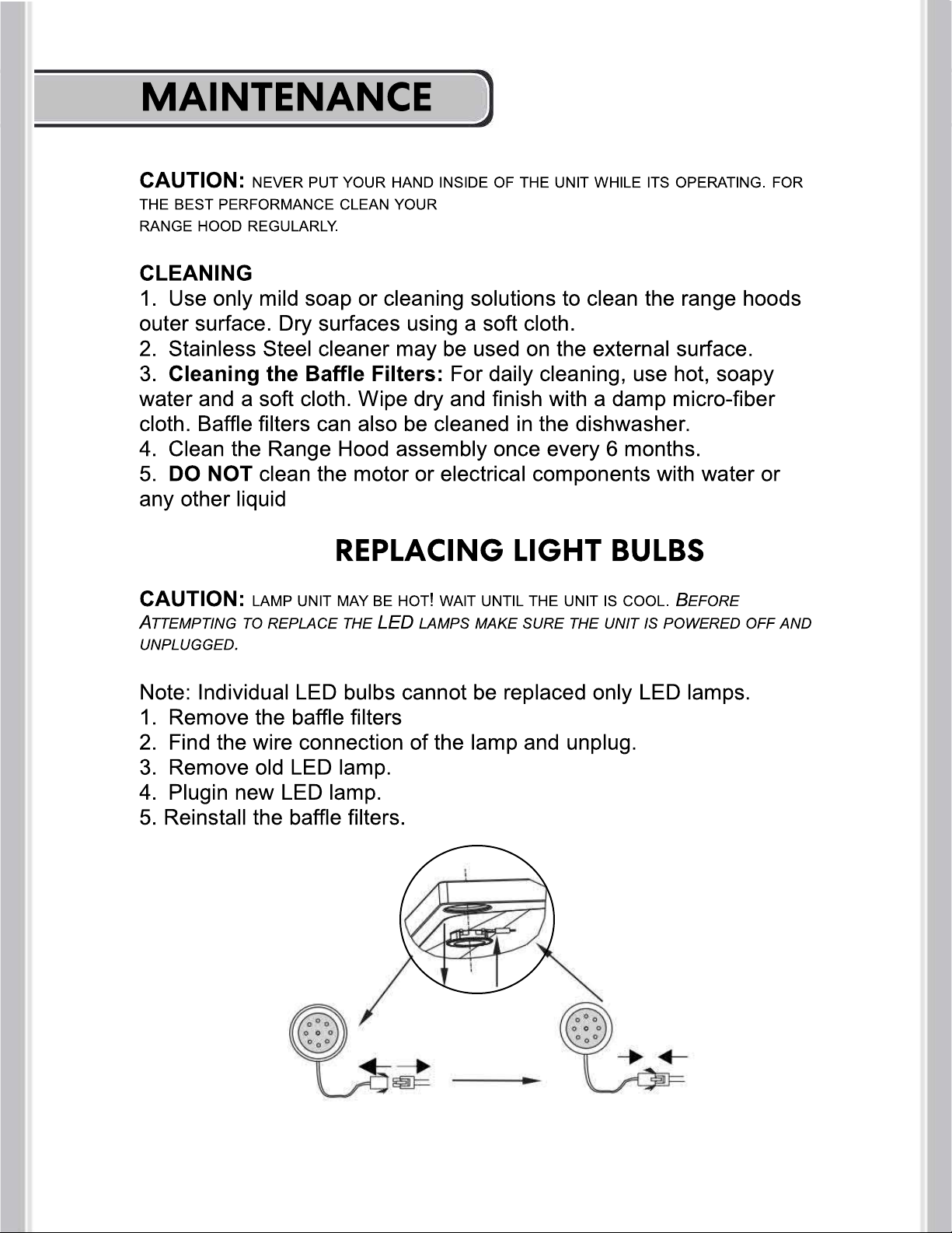
Light bulbs went out
A. Replace with a new LED lamp assembly.
B. Remove baffle filters, reach inside behind
the control panel and locate the wire with clip
behind the light housing. Make sure the light
is securely plugged in.
IF YOU HAVE TRIED ALL SOLUTIONS AND STILL EXPERIENCE ISSUES, PLEASE CALL SUPPORT:
1-888-784-3108.
18
Page 20

19
 Loading...