

Page 1

I N S P I R I N G T H E W O R L D ’ S K I T C H E N
UNDER CABINET RANGE HOOD
COS-18U48
INSTALL & USER GUIDE
IMPORTANT SAFETY INSTRUCTIONS
Carefully read the following Important information redarding installation
safety and maintenance. Keep these instruction for future reference.
COS-18U48 INSTALL & USER GUIDE
Page 2
THANK YOU FOR YOUR PURCHASE
Thank you for your purchase. We know that you have many brands and
products to choose from and we are honored to know that you have decided
TABLE OF CONTENTS
to take one of our products into your home and hope that you enjoy it.
COSMO appliances are designed according to the strictest safety and performance
standard for the North American market. We follow the most advanced
manufacturing philosophy. Each appliance leaves the factory after thorough
quality inspection and testing. Our distributors and our service partners are
ready to answer any questions you may have regarding how to install, use and
care for your products. We hope that this manual will help you learn to use the
product in the safest and most effective manner .
If you have any questions or concerns, please contact the dealer from whom you
purchased it, or contact our Customer Support at:
1-888-784-3108.
SAFETY INSTRUCTIONS 4
STAINLESS STEEL BAFFLE FILTERS 5
DIMENSIONS DIAGRAM 6
PARTS DIAGRAM 7
INSTALLATION REQUIREMENTS 8
PRE-INSTALLATION REQUIREMENTS 9
INSTALLATION INSTRUCTIONS 10-15
OPERATION INSTRUCTIONS 16
MAINTENANCE 17-18
TROUBLESHOOTING 19
WARRANTY & SERVICE 20-21
2 3
Page 3
IMPORTANT SAFETY INSTRUCTIONS
STAINLESS STEEL BAFFLE FILTERS
Read all instructions before using this appliance. Save
these instructions for future references.
Approved for residential appliances. For residential use only.
Due to the weight and size of these vent hoods and to reduce the risk of personal injury or damage to the product
TWO PEOPLE ARE REQUIRED FOR PROPER INSTALLATION
CAUTION
FOR GENERAL VENTILATING USE ONLY. DO NOT USE TO
EXHAUST HAZARDOUS OR EXPLOSIVE MATERIALS OR
VAPORS.
CAUTION
To reduce risk of fire and to properly exhaust air, do
not vent exhaust air into spaces within walls,
ceilings, attics, crawl spaces, or garages.
WARNING
TO REDUCE THE RISK OF FIRE, USE ONLY METAL
DUCT WORK. Install this hood in accordance with all
requirements specified
WARNING
GROUNDING INSTRUCTIONS
This appliance must be grounded. In the event of an elec-trical
short circuit, grounding reduces the risk of electric shock
by providing an escape wire for the electric current. This
appliance is equipped with a cord having a grounding wire with a
grounding plug. The plug must be plugged into an outlet that is
properly installed and grounded.
WARNING - IMPROPER GROUNDING CAN
RESULT IN A RISK OF ELECTRIC SHOCK.
Consult a qualified electrician if the grounding instructions are
not completely understood, or if doubt exists as to whether the
appliance is properly grounded.
Do not use an extension cord. If the power supply cord is too
short, have a qualified electrician install an outlet near the
appliance.
WARNING
WARNING
TO REDUCE THE RISK OF FIRE, ELECTRIC SHOCK,
OR INJURY TO PERSONS, OBSERVE THE FOLLOWING:
1. Use this unit only in the manner intended by the manufactur
er. If you have questio
2. Before servicing or cleaning the unit, switch power off
at service panel and lock service panel disconnecting means
to prevent power from being switched
the service disconnecting means cannot be locked, securely
fasten a prominent warning device, such as a tag, to the
service panel.
3. Installation Work and Electrical Wiring Must Be Done
By Quali ed Person(s) In Accordance With all Aplicable
Codes & Standards, Including Fire-ra
4. Suf cient air is needed for proper combustion an
exhausting of gases through the flue
burning equipment to prevent back- drafting. Follolow the
heating equipment manufacturers guideline and safety
standards such as those published by the National Fire
Protec
tion Ass
Heating, Refrigeration and Air Conditioning Engineers
(ASHRAE), and the local code authorities.
5. When cutting or drilling into wall or ceiling, do not
damage electrical wiring and other hidden utilities.
Ducted systems must always be vented to the outdoors.
6.
ociation
FPA), the American Socie
(N
ns, contac
t the manufacture
on acci-dentally. When
(Chimney) of fuel
ted Construction.
d
ty for
r.
TO REDUCE THE RISK OF INJURY TO PERSONS, IN THE
EVENT OF A RANGE TOP GREASE FIRE, OBSERVE THE
FOLLOWING:
• SMOTHER FLAMES with a close-fitting lid, cookie sheet,
or metal tray, then turn off the burner. BE CAREFUL TO
PREVENT BURNS. If the flames do not go out immediate-ly,
EVACUATE AND CALL THE FIRE DEPARTMENT.
• NEVER PICK UP A FLAMING PAN – You may be burned.
• DO NOT USE WATER, including wet dishcloths or towels –
a violent steam ex-plosion will result.
• Use an extinguisher ONLY if:
1. You know you have a Class ABC extinguisher, and you
already know how to operate it.
2. The fire is small and contained in the area where it started.
3. The fire department is being called.
4. You can fight the fire with your back to an exi
Always leave safety grills and lters in place.Without these
components, operating blowers could catch onto hair, ngers and
loose clothing.
The manufacturer declines all responsibility in the event
of failure to observe the instructions given here for
installation,maintenance and suitable use of the product. The
manufacturer further declines all responsability for injury due to
negligence and the warranty of the unit automatically expires due
to improper maintenance.
WARNING
WARNING
To Reduce The Risk Of Fire Or Electric Shock, Do Not Use
This Hood With Any External Solid State Speed Control
Device.
WARNING
Unplug or disconnect the appliance from the power
supply before servicing.
WARNING – TO REDUCE THE RISK OF A RANGE TOP
GREASE FIRE:
A. Never leave surface units unattended at high settings.
Boilovers cause sm
Heat oils slowly on low or medium settings.
B. Always turn hood ON when cooking at high heat or when
flaming food (i.e. Crepes Suzette, Cherries Jubilee Peppercorn
Beef Flambe).
C. Clean ventilating fans frequently. Grease should not be
allowed to accumulate on fan or filte .
D. Use proper pan size. Always use cookware appropriate for
the size of the surface element.
oking and greasy spillovers that may ignite.
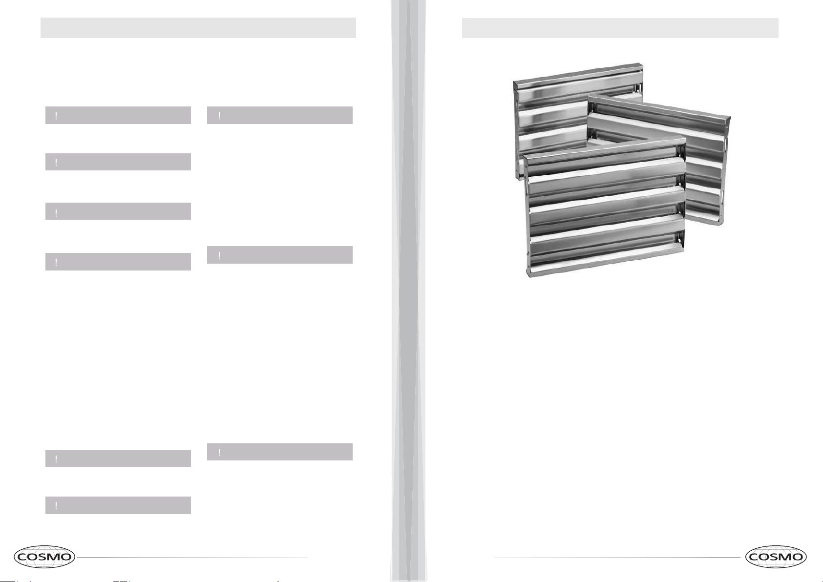
About Your New Filters
Stainless Steel Baffle Filters do not need linings or mesh inside of
the filters and are completely constructed out of stainless steel. The
stainless steel construction allows them to be used again and
again after being cleaned or going through the dishwasher.
How do Permanent Filters work?
They function by forcing the grease filled air to quickly and
continuously change direction as it passes through the filter.
The grease is unable to change direction as fast as the air
carrying them, they end up getting caught on the metal
blades and then trapped into the filter tray.
These filters are both efficient and require less maintenance.
Additional Filters can be purchased from:
www.cosmoappliances.com
4 5
Page 4
12 in.
17.9 in.
DIMENSIONS DIAGRAM
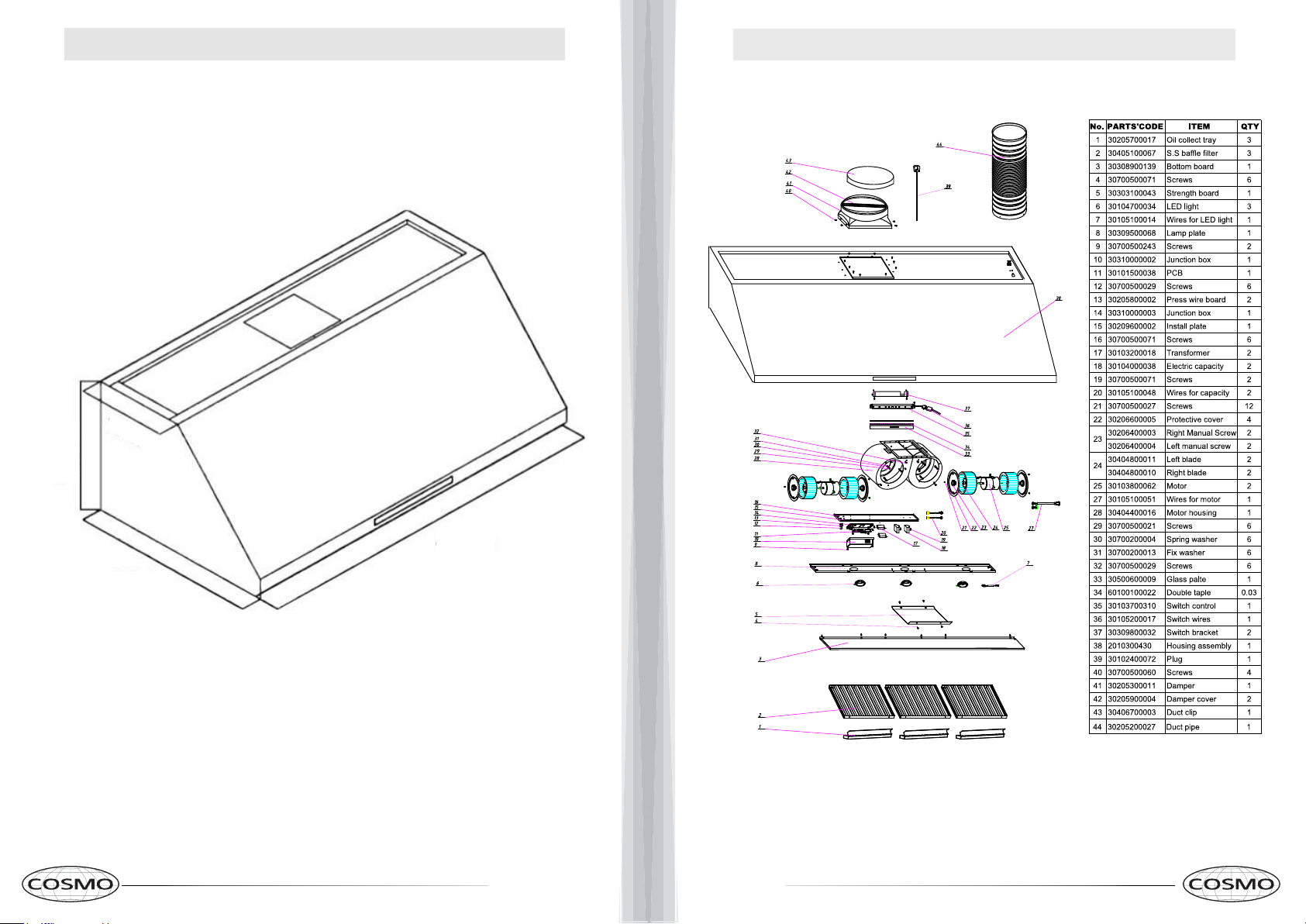
PARTS DIAGRAM
25 in.
COS-18U48
47.9 in.
6 7
Page 5

INSTALLATION REQUIREMENTS
PRE-INSTALLATION INSTRUCTIONS
Sufficient air is needed for proper combustion and exhausting of gases
through the chimney of fuel burning equipment to prevent backdrafting.
Follow the cooking equipment manufacturers guideline and safety
standards such as those published by the National Fire Protection
Association (NFPA), the American Society for Heating, Refrigeration
and Air Conditioning Engineers (ASHRAE), and local code.
When cutting or drilling into wall or ceiling, do not damage electrical
wiring and other hidden utilities. Ducted systems must always be
vented outdoors.
BEFORE YOU BEGIN
Read these instructions completely and carefully.
●
IMPORTANT – Save these instructions for local inspector’s usage.
●
Note to installer – Be sure to leave these instructions with the Consumer.
●
Note to Consumer – Keep these instructions for future reference.
●
Skill Level – Installation of this vent hood requires basic mechanical and
electrical skills.
Proper installation is the responsibility of the installer.
●
CAUTION:
Due to the weight and size of these vent hoods and to reduce the
risk of personal injury or dam-age to the product, TWO PEOPLE
ARE REQUIRED FOR PROPER INSTALLATION.
WARNING
To reduce the risk of the fire or electrical shock, do not use this range
hood with any external solid-state speed control device. Any such
alteration from original factory wiring could result in damage to the unit
and/or create an electrical safety hazard. TO REDUCE THE RISK OF
THE FIRE, USE ONLY METAL DUCTWORK. These vent hoods are
designed to be installed onto a wall or beneath a cabinet.
:
Please read the instructions carefully. Unpack the Range Hood and check that all
•
functions are working before installing.
Ensure that the voltage (V) and the frequency (Hz) indicated on the sticker match
•
the voltage and frequency at the installation site.
Check that the area behind the installation surface to be drilled is clear of any
•
electrical cables or pipes, etc.
The stainless steel surfaces of the Range Hood are very easily damaged during
•
installation if scratched or bumped by tools. Please take care to protect the
surfaces during installation.
Protect the cooktop surface below with cardboard, or the like, to prevent
•
damage occurring during installation.
The manufacturer shall not be held liable for consumer’s failure to observe and
•
follow all pre-installation procedures and safety regulations.
The vertical distance from the cooking surface to the bottom of the range hood
•
should be at least 24 in. to 36 in. for best performance.
Determine if your installation will be top venting or back venting, and ensure
•
that the openings in the cabinet or wall are in the appropriate locations and
appropriate size.
If this is a new installation, choose the venting method that suits your needs. Cut
•
out openings for the damper and for power access in the cabinet bottom or
exterior wall, depending on the installation method chosen.
DUCTWORK PLANNING
These vent hoods are equipped for 8" round ductwork. This hood may be vented
•
vertically through upper cabinet or ceiling. A duct transition piece is supplied for
vertical exhaust. You may use elbows (sold separately) to vent horizontally
through the rear wall.
Determine the exact location of the vent hood.
•
Plan the route for venting exhaust to the outdoors.
•
Use the shortest and straightest duct route possible. For satisfactory
•
performance,duct run should not exceed 12.5 feet. equivalent length for any duct
configurations.
Use metal ductwork only.
•
WALL FRAMING FOR ADEQUATE SUPPORT
These vent hoods are heavy. Adequate structural support must be provided.
Actual length of straight duct plus duct fitting must equivalent. Equivalent
*
lengths of duct pieces are based on actual tests conducted by Evaluation
Engineering and reflect requirements for good venting performance with any
ventilation hood.
IMPORTANT:
Plug the Unit in and Test all Functions Before Installing.
8 9
Page 6

INSTALLATION INSTRUCTIONS INSTALLATION INSTRUCTIONS
24” (610 mm) Min / 36” (914 mm) Max
CAUTION: HOOD MAY HAVE VERY SHARP EDGES; PLEASE WEAR
PROTECTIVE GLOVES WHENEVER IT IS NECESSARY TO REMOVE ANY
PARTS FOR INSTALLING, CLEANING OR SERVICING.
IMPORTANT:
•
System must vent to the outside (roof or side wall).
• DO NOT vent system into an attic or other enclosed
area.
• DO NOT use laundry-type wall caps.
• Use metal/aluminum vent only. A rigid metal/aluminum vent is recommended.
DO NOT use a plastic vent.
•
• Always keep the duct clean to ensure proper airflow.
• Calculate the following figures before installation:
1. Distance from the floor to the ceiling
2. Distance between the floor and the countertop/
stove
3. A distance of 24” to 36” is recommended
between stove top and the bottom of range hood.
30” minimum is required for gas stove tops.
4. Height of hood and duct cover.
Height and Clearance
For the most efficient and quiet operation:
• It is recommended that the range hood be vented
vertically through the roof through at least 10” round metal/
aluminum vent work.
• Use no more than three 90° elbows.
•
Make sure there is a minimum of 24” of straight vent between the elbows if more than one elbow is used.
•
The length of vent system and number of elbows should
be kept to a minimum to provide efficient performance.
• The vent system must have a damper.You may remove
damper flaps from damper to increase air flow.
•
Use silver tape or duct tape to seal all joints in the vent
system.
•
Use caulking to seal exterior wall or roof opening
around the cap.
CAUTION: HOOD MAY HAVE VERY SHARP EDGES; PLEASE WEAR
PROTECTIVE GLOVES WHENEVER IT IS NECESSARY TO REMOVE
PARTS FOR INSTALLING, CLEANING OR SERVICING.
A 47.75" x 2" x 4" wooden support (sold separately) is
required to properly install this Range Hood.
Install Wood Support
1. Locate at least two vertical studs at the wood mounting location by tapping drywall or by using a stud finder.
2. Position the supplied wood support
the support, drywall and into the studs.
3. Secure the wood support to two or more vertical studs with wood screws (not provided).
4. Use threaded drywall anchors when mounting the hood onto sheet rock. Mounting the hood into wall studs or
lumbars is highly recommended.
” ( mm) below the cabinet and drill 1/8” (3.175 mm) pilot holes through
0.5”
(12.7mm)
Wood Support
10 11
Page 7

INSTALLATION INSTRUCTIONS
Keyhole
Keyhole
INSTALLATION INSTRUCTIONS
Install Range Hood Mounting Screws
1. Mark the screw holes onto the bottom of cabinet by
Remember to compensate for the size of the
wooden support frame.
You will need to cut the holes for the power cord and the damper hole under the cabinet.
3.Install the range hood mounting screws, leaving the
clearance for mounting the range hood.
Top View
Keyhole Locations
0.69 in.
7.09 in.
17.5mm
0.69 in.
1. Lift the range hood and place over the protruding mounting screws; the keyhole slots on the top of the range
hood should engage with the protruding mounting screws.
2. Gently slide the range hood backwards until it cannot
2-1/8 in.
2.75 in.
19.82 in.
8.27 in.
3.61 in.
47.9 in.
2.41 in.
slide back any further. Finish screwing in the mounting screws.
measuring the holes located on top of the unit.
screws protruding a 1/4” (6.3 mm) to allow
0.69 in.
2-1/8 in.
2-1/8 in.
19.82 in.7.44 in.
2.75 in.
17.5mm
7.09 in.
17.5mm
0.69 in.
Secure Back of Range Hood
Using the wood screws, secure the back of the range hood into the wood support through the
keyhole slots in the rear of the range hood body.
Keyhole
1.18”
2.38”
15.75 “
31.5”
17.95”
12 13
Page 8

INSTALLATION INSTRUCTIONS
INSTALLATION INSTRUCTIONS
Install Damper
1.
Position the damper over the damper adapter and secure using the screws provided.
f DAMPER
f WALL
f DAMPER ADAPTER
INSTALLING THE EXHAUST DUCTING
Important:
Remove the packaging tape on the damper (located at the top of the unit) and make sure the flaps are
1.
able to move freely.
Use HVAC foil tape to wrap all the duct joints for an airtight seal
2.
Connect to AC Outlet
•
Connect AC plug into a grounded AC outlet having 120V,
60Hz. Place the outlet at a maximum distance of
33-1/2” (851 mm) from where the cord exits on the hood.
•
SEE IMPORTANT INSTRUCTIONS BELOW
IMPORTANT:
•
Observe all governing codes and ordinances.
•
It is the customer’s responsibility to contact a qualified electrical installer.
•
If codes permit and a separate ground wire is used, it is recommended that a qualified electrician
determine that the ground path is adequate. A 120-Volt, 60 Hz, AC-only, fused electrical supply is
required on a separate 15-amp circuit, fused on both sides of the line.
•
DO NOT ground to a gas pipe.
•
Check with a qualified electrician if you are not sure that the range hood is properly grounded.
•
DO NOT have a fuse in the neutral or ground circuit.
IMPORTANT: Save this Installation Guide for electrical inspector’s use.
GROUNDING INSTRUCTIONS:
•
This appliance must be grounded. In the event of an electrical short-circuit, grounding reduces the risk of
electric shock by providing an escape wire for the electric current.
•
This appliance is equipped with a cord having a grounding wire with a grounding plug. The plug must be
plugged into an outlet that is properly installed and grounded.
WARNING: Improper grounding can result in a risk of electric shock.
•
Consult a qualified electrician if the grounding instructions are not completely understood, or if doubt
exists as to whether the appliance is properly grounded. DO NOT use an extension cord. If the power
supply cord is too short, have a qualified electrician install an outlet near the appliance.
3-Pronged Plug
Ground Plug
3-Prong Receptacle
Important:
To provide extra support and to reduce the vibration, the appliance must fix onto the concrete wall
•
Important:
Install ductwork, making connection in direction of airflow as illustrated.
Secure joints in ductwork with sheet metal screws.
Wrap all duct joints with HVAC foil tape for an airtight seal.
14 15
Page 9

OPERATING INSTRUCTIONS
MAINTENANCE
Using the Fan
Press to begin low
speed. Screen will display
u
F1.
Press to increase speed
suction. Screen will display
increments as F2, F3, F4.
Press again to decrease
suction. Screen will display
00.
Press to begin high
v
speed suction. Screen will
display F3.
Press again to begin
high speed suction to F4.
Press again to stop
suction. Screen will display 00.
Using the Time Delay Function
u
v
w
x
to activate the Press
Time Delay Function.
Screen will display “15
minutes”.
Press to increase or to
decrease the time period
for the Time Delay
Function.
to cancel the Press
Time Delay Function.
The light will turn off at the end of the set time period if
Time Delay Function is activated while the light is on.
Turning the Light On of Off
Press
u
to turn light on
and again to turn light
off.
Care and Cleaning
The metal baffles channel grease
released by foods on the cook top into the
drip trays. The baffles also help prevent
flaming foods on the cook top
from damaging the inside of the hood. For
this reason, the baffles must ALWAYS be
in place when the hood is used.The
grease baffles and drip trays should be
cleaned once a month, or as needed.
To clean the grease baffles and drip
trays:
Drain and wipe all excess grease with a
dry paper towel, Soak them and then
swish them around in hot water and
detergent. Don’t use ammonia or
ammonia products because they will
darken the metal. Do not use abrasives
or oven cleaners. Rinse, shake and let
them dry before replacing. They may
also be cleaned in an automatic
dishwasher.
To remove:
Grasp the filter handles and pull them up,
forward and out. Grasp the drip tray and
carefully lift it up and out of the hood
track.
To replace the drip trays:
1. Place and seat the drip tray
into the hood rack.
2. Slide them left and right until
all trays are side-by-side in
place in the track
To replace the baffles filters:
1. Hold the baffle filter by the two handles.
2. Place the up end of the baffle
against the inside front of the
hood.
3. Slide it up and push the
bottom end back until it firmly
seats into place
16 17
Page 10

MAINTENANCE
TROUBLESHOOTING
CAUTION: NEVER PUT YOUR HAND INSIDE OF THE UNIT WHILE ITS OPERATING. FOR
THE BEST PERFORMANCE CLEAN YOUR
RANGE HOOD REGULARLY.
CLEANING
1. Clean the Range Hood assembly once every 6 months.
2. DO NOT clean the motor or electrical components with water or
any other liquid
REPLACING LIGHT BULBS
CAUTION: LAMP UNIT MAY BE HOT! WAIT UNTIL THE UNIT IS COOL. BEFORE
ATTEMPTING TO REP LACE THE LED LAMPS MAKE SURE THE UNIT IS POWERED OFF AND
UNPLUGGED.
Note: Individual LED bulbs cannot be replaced, only entire LED lamps.
1. Remove the baffle filters
2. Find the wire connection of the lamp inside the unit and unplug.
3. Remove old LED lamp by pushing it out of its hole from the inside.
4. Plug in new LED lamp.
5. Reinstall the baffle filters.
CAUTION: ALWAYS UNPLUG UNIT FROM POWER BEFORE SERVICING
PROBLEM
My range hood is
noisy
My range hood has
poor performance..
My range hood shakes.
A. The range hood and cook top
B. There are too many open
C. The motor performance has
D. Check and make sure the
A. The installation is not secure.
B. The fan is broken or not
C. The motor is loose. Check
SOLUTION
A. Check inside the range
hood for any loose debris and
remove.
are too far away from each
Optimal distance is 24” to 36”
other.
windows or doors in the area.
Close some doors or
windows.
decreased due to wear.
Replace motor.
tape holding down the
damper flaps at the vent hole
are removed before use.
Check again and make sure
the installation hardware is
securely mounted.
balanced. Realign or replace
fan.
and make sure the motor is
solidly mounted to the unit.
TOOLS
Phillips Screwdriver
Phillips Screwdriver
Phillips Screwdriver
18 19
The motor no
longer runs.
Light bulbs went out.
A. Replace control panel or
circuit board.
B. Replace with new motor
assembly.
A. Replace with a new LED
lamp assembly.
Phillips Screwdriver
Phillips Screwdriver
Page 11

WARRANTY AND SERVICE
For full warranty details on this product please visit:
http://www.cosmoappliances.com/warranty
TO RECEIVE WARRANTY SERVICE, YOUR
PRODUCT MUST BE REGISTERED. TO REGISTER, VISIT:
WWW.COSMOAPPLIANCES.COM/WARRANTY
IMPORTANT
Do Not Return This Product To The Store If
you have a problem with this product, please contact
Cosmo Customer Support at
+1(888)784-3108
DATED PROOF OF PURCHASE, MODEL #, AND SERIAL #
REQUIRED FOR WARRANTY SERVICE
IMPORTANT
Ne pas Réexpédier ce Produit au Magasin
Pour tout problème concernant ce produit, veuillez contacter
le service des consommateurs Cosmo Customer Support au
+1(888) 784-3108
UNE PREUVE D’ACHAT DATEE EST REQUISE POUR BENEFICIER DE
LA GARANTIE.
SCAN TO REGISTER
Si tiene algún problema con este producto, por favor contacte el
NECESITA UNA PRUEBA DE DE COMPRA FECHADA, NÚMERO DE
20 21
IMPORTANTE
No regrese este producto a la tienda
AYUDA AL CLIENTE COSMO al
+1(888)784-3108
(Válido solo en E.U.A).
MODELO Y DE SERIE PARA EL SERVICIO DE LA GARANTÍA
Correct Disposal of this product:
This marking indicates that this appliance should not
be disposed with other household wastes. To prevent
possible harm to the environment or human health
from uncontrolled waste disposal, recycle it responsibly to
promote the sustainable reuse of material resources.
Page 12

Cosmo is constantly making efforts to improve the quality and
performance of our products, so we may make changes to our
appliances without updating this manual.
Electronic version of this manual is available at:
www.cosmoappliances.com
 Loading...