

Page 1
WALL MOUNT RANGE HOOD
This manual is made with 100 % recycled paper.
Electronic version of this manual is available at:
www.cosmoappliances.com
Page 2
Thank you for your purchase. We know that
you have many brands and products to
choose from and we are honored to know
that you have decided to take one of our
products into your home and hope that you
enjoy it.
Our appliances are designed according to
the strictest safety and performance
standard for the North American market. We
follow the most advanced manufacturing
philosophy. Each appliance leaves the
factory after thorough quality inspection and
testing. Our distributors and our service
partners are ready to answer any questions
you may have regarding how to install, use
and care for your range hood.
We hope that this manual will help you learn
to use the product in the safest and most
effective manner and care for it so that it
may give you the highest satisfaction in
cooking for years to come. If you have any
questions or concerns, please contact the
dealer
from whom you purchased it, or
contact our Customer Support at
1-888-784-3108.
The manual also includes directions for the
professional installer that will install the
product in your home. We recommend using
trained personnel for professional
installation.
Please keep this manual for future use
Thank You
2
1
Page 3
2
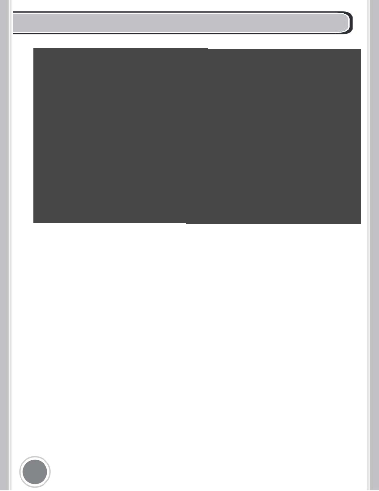
STAINLESS STEEL BAFFLE FILTERS
About Your New Filters
Stainless Steel Baffle Filters do not need linings or mesh inside of the filters and are
completely constructed out of stainless steel. The stainless steel construction allows
them to be used again after being cleaned or going through the dishwasher.
How do Baffle Filters Work?
They function by forcing the grease filled air to quickly and continuously change direction
as it passes through the filter. The grease is unable to change direction as fast as the air
carrying them, they end up getting caught on the metal blades and then trapped into the
filter tray.These filters are both efficient and require less maintenance.
Page 4
TABLE OF CONTENTS
PARTS DIAGRAM
INSTALLATION REQUIREMENTS
INSTALLATION PROCEDURES
OPERATING INSTRUCTIONS
MAINTENANCE
TROUBLESHOOTING
WARRANTY AND SERVICE
06
08
11
12
13
14
04
3
Page 5
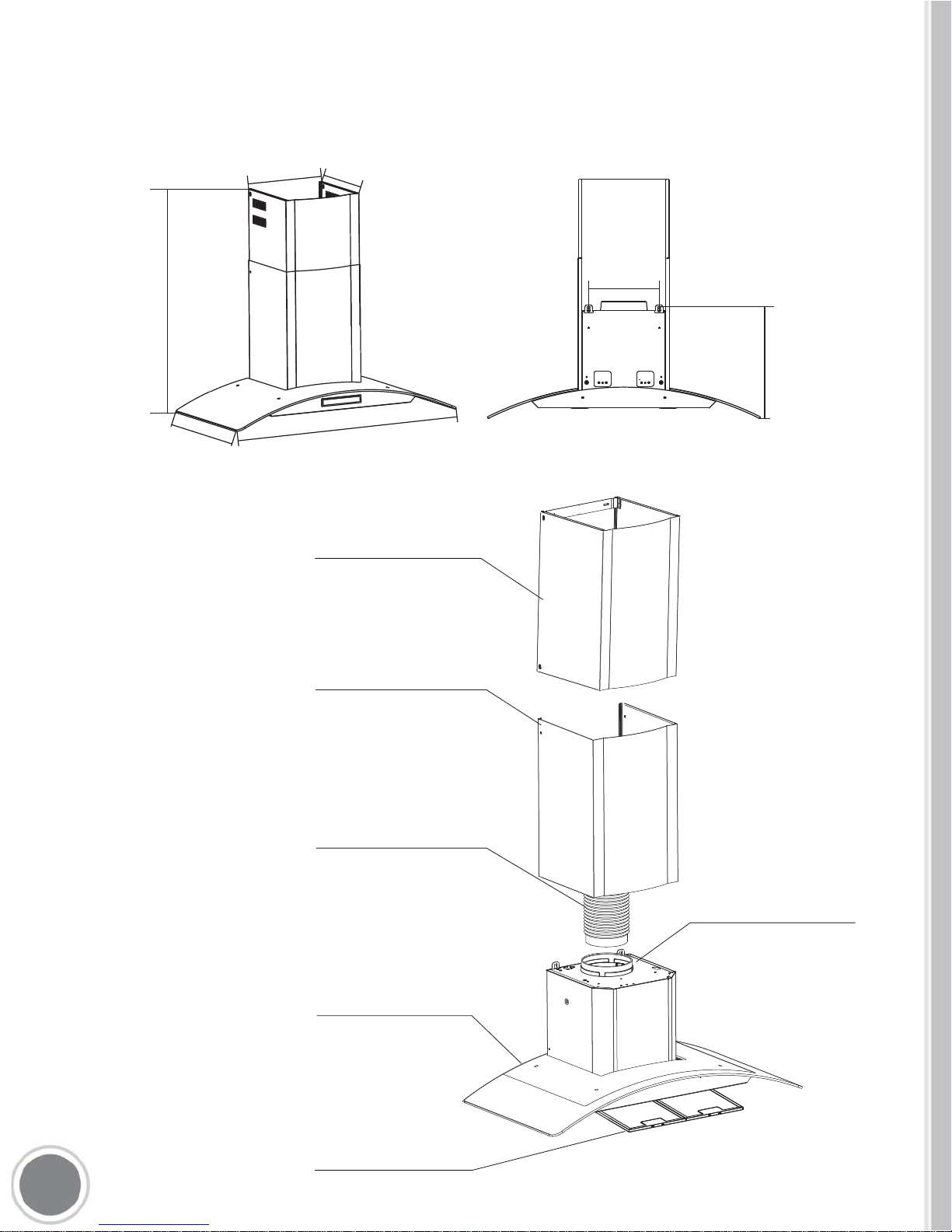
PARTS DIAGRAM
4
MAIN PARTS
11.8"
11.1"
20.7"-36.4"
18.7"
30"/36"
9.1"
14.5"
668A 750/900 - 668AS 750/900
Inner chimney cover
1.
Outer chimney cover2.
Exhaust pipe3.
6.. Grease Filters
Tempered Glass
5.
Blower Assembly
4.
Page 6

5
Outer chimney cover2.
Exhaust pipe3.
Inner chimney cover
1.
Stainless Cover
4.
5. Grease Filters
MAIN PARTS
PARTS DIAGRAM
63190FT 750/900 - COS-631 750/900
26.8" - 41.7"
1.60"
18.9"
30" / 35"
8.4"
7.3"
10.77"
7.48"
Page 7

INSTALLATION REQUIREMENTS
1. Do not install the range hood where there are many open doors or
windows.This will cause reduced performance. (Fig. 1)
2. Install the range hood right above the cooktop. The optimal
distance between the cooktop and lower edge of the range hood is
25” to 35”. (Fig. 2)
3. In order to get optimal performance, do not over extend the
exhaust pipe and avoid unnecessary bending. (Fig. 3)
4. After hanging the unit on the wall, ensure the range hood is straight
and leveled. (Fig. 4)
5. The air outlet must be connected to chimney flues or combustion
gas ducts. Under no circumstances should the air outlet be connected
to ventilation ducts for rooms in which fuel-burning appliances are
installed.
6
25" to 35"
Page 8

Parts List:
A. Rubber Disc x 2 - Padding for the back of the Range Hood (Optional).
To install screw on back in holes located under mounts.
B. Metal Screws x 2 (To secure rubber disc to Range Hood)
C. Wood Screws x 6 (Only four will be used)
D. Plastic Anchors x 6 (Only four will be used)
E. Metal Screws x 2 (Locks Chimney to Housing)
C.
D.
A.
B.
E.
A.
Parts List
7
Page 9

CAUTION: HOOD MAY HAVE VERY SHARP EDGES; PLEASE WEAR
PROTECTIVE GLOVES WHENEVER IT IS NECESSARY TO REMOVE ANY
PARTS FOR INSTALLING, CLEANING OR SERVICING.
Step 1:
Place the range hood on the wall and mark
the position where you want to install. A height
of 25” to 35” is recommended for optimal
performance.
Step 2:
Step 3:
Find the exhaust pipe, attach it to the top air
outlet. Make sure it is connected tightly to the
air outlet.
8
INSTALLATION PROCEDURES
0.50"
9.1"
14.5"
A. Find the 2 mounting holes in the back of the
range hood. Mark their locations at the installation
location with a pencil or marker.
B. Drill 5/16 (8mm) hole at each of the marked
locations.
C. Insert anchors into each drilled hole. Firmly
screw them into place.
D. Hang your Range Hood into place by aligning the
anchors with the two mounting holes in the back of
the range hood.
Page 10

Step 4:
The bracket may already come installed,
if so skip Step 4.
Find the bracket. Match the holes of the
inner chimney cover and screw mounting
bracket on with type M4 screws.
Step 5:
Insert the inner chimney cover into the outer
chimney cover. Note that the inner chimney
cover must slide into the outer chimney covers
orientation slot.
Step 6:
Attach outer chimney cover to the unit body
with type M4 screws.
Step 7:
A. Extend the inner chimney cover to the
height to which you want. Mark the two holes
of the inner chimney to the wall.
B. Drill two 8mm holes 2” - 2.5” into the wall
where you marked in step. A.
C. Press expanding tube (anchors) into the
holes.
D. Extend the inner chimney cover and screw
it into the wall where you placed the
expanding tube (anchors) using two wood
screws.
9
Mounting Bracket
Inner Chimney Cover
Outer Chimney Cover
Inner Chimney Cover
Outer Chimney Cover
Page 11

Step 8:
Extend the exhaust pipe to the vent-pipe of your
building or to outside. For optimal performance
try to have the least amount of bending
possible.
Step 9:
Insert and install filters according to the
diagram.
10
Page 12

OPERATING INSTRUCTIONS
A. Light. Press to turn light on / off.
B. Highest Fan Setting
C. Medium Fan Setting
D. Lowest Fan Setting
E. Power Button. Press to turn unit on / off.
11
A B C D E
A. Light. Press to turn light on / off.
B. Timer Button
C. Display Panel
D. Fan Speed Button
E. Power Button. Press to turn unit on / off.
Soft Touch Controls
668AS 750 / 900 - 63190S / 63175S
Push Button Controls
668A 750 / 900 - 63190 / 63175 - 63175E / 63190E
Page 13

MAINTENANCE
CAUTION: NEVER PUT YOUR HAND INSIDE OF THE UNIT WHILE ITS OPERATING. FOR
THE BEST PERFORMANCE CLEAN YOUR
RANGE HOOD REGULARLY.
CLEANING
1. Use only mild soap or cleaning solutions to clean the range hoods
outer surface. Dry surfaces using a soft cloth.
2. Stainless Steel cleaner may be used on the external surface.
3. Cleaning the Baffle Filters: For daily cleaning, use hot, soapy
water and a soft cloth. Wipe dry and finish with a damp micro-fiber
cloth. Baffle filters can also be cleaned in the dishwasher.
4. Clean the Range Hood assembly once every 6 months.
5. DO NOT clean the motor or electrical components with water or
any other liquid
REPLACING LIGHT BULBS
CAUTION: LAMP UNIT MAY BE HOT! WAIT UNTIL THE UNIT IS COOL. BEFORE
ATTEMPTING TO REPLACE THE LED LAMPS MAKE SURE THE UNIT IS POWERED OFF AND
UNPLUGGED.
Note: Individual LED bulbs cannot be replaced only LED lamps.
1. Remove the baffle filters
2. Find the wire connection of the lamp and unplug.
3. Remove old LED lamp.
4. Plugin new LED lamp.
5. Reinstall the baffle filters.
12
Page 14

TROUBLESHOOTING
CAUTION: ALWAYS UNPLUG UNIT FROM POWER BEFORE SERVICING
PROBLEM SOLUTION TOOLS
My range hood is
noisy.
A. Check inside the range hood
for any loose debris and remove.
Phillips Screwdriver
My range hood has
poor performance..
A. The range hood and cooktop
are too far away from each other.
Optimal distance is 25” to 35”
B. There are too many open
windows or doors in the area.
Close some doors or windows.
C. The motor performance has
decreased due to wear. Replace
motor.
D. Check and make sure the tape
holding down the damper flaps at
the vent hole are removed before
use.
Phillips Screwdriver
My range hood
shakes.
A. The installation is not secure.
Check again and make sure the
installation hardware is securely
mounted.
B. The fan is broken or not
balanced. Realign or replace fan.
C. The motor is loose. Check and
make sure the motor is solidly
mounted to the unit.
Phillips Screwdriver
The motor no longer
runs.
A. Replace control panel or
circuit board.
B. Replace with new motor
assembly.
Phillips Screwdriver
Light bulbs went out.
A. Replace with a new LED lamp
assembly.
Phillips Screwdriver
13
Page 15

14
WARRANTY AND SERVICE
Limited Warranty
This unit comes with 1 Year Manufacturer’s Part Warranty. Within 1 year after date
of receiving the product, Cosmo will replace any functional parts that are defective.
Functional parts are those components/parts that are critical to the performance of
the product’s essential function. Non-functional parts are those that are a cosmetic
feature of the product such as knobs, grates, other metal bodies/surfaces, etc.
A. Warranty does not cover failure as result of: misuse, abuse, rust or
corrosion, spilled liquids or foreign objects found inside the unit; repair of
damage caused by accident,
theft, fire, flood, external causes such as, but not limited to, blow fuses,
inadequate electrical power, water and gas lines beyond the equipment, or
any use of the product not authorized by the manufacturer.
B. The maximum liability of the warranty for product replacement or repair
shall not exceed the original purchase price of the product.
C. Cosmo reserves the right to repair or replace the covered product with a
comparable feature model of like kind.
D. Warranty does not cover deterioration of the appearance of the product,
any cosmetic part such as paint, porcelain, glass, dents, scratches, chips,
rust or peeling.
E. Any damage resulting from unauthorized replacement parts, improper
service or modifications made to the covered product are not covered.
F. Cosmo is released from all liability due to indirect, consequential or
incidental damages.
 Loading...