

Cosmik Aviation EV-97 teamEUROSTAR UK Pilot Operating Handbook
EV-97 teamEUROSTAR UK

PILOT’S OPERATING HANDBOOK FOR MICROLIGHT AEROPLANE
EV-97 teamEurostar UK
Model: .............................................
Registration: ..............................................
Serial No. ..............................................
Approved by: ...........................................................
This aeroplane must be operated in compliance with the
information and limitations contained herein.
This POH must be available on
board the aeroplane.
WARNING
This aeroplane is not fitted with a certified engine. A power failure
can occur at any time. Never fly over any area on to which a safe
landing cannot be made in the event of an engine failure.
POH/EUR/01 Issue 2 Page 2 of 42
Amendment Record
Issue Details of Change Date Authorised
1 Initial issue
14/07/03
2
Addition of optional hourmeter and warning
lamp – P37
16/8/04
POH/EUR/01 Issue 2 Page 3 of 42

Table of Contents
SECTION 1 – GENERAL INFORMATION AND TECHNICAL DATA.............................6
1.1 Introduction...............................................................................................................................6
1.2 Certification basis.....................................................................................................................6
1.3 Warnings, cautions and notes..................................................................................................6
1.4 Descriptive Data........................................................................................................................6
SECTION 2 - LIMITATIONS.................................................................................................9
2.1 Introduction...............................................................................................................................9
2.2 Airspeed.....................................................................................................................................9
2.3 Airspeed indicator markings....................................................................................................9
2.4 Powerplant...............................................................................................................................10
2.5 Powerplant Instrument Markings.........................................................................................11
2.6 Miscellaneous instrument markings......................................................................................12
2.7 Weight......................................................................................................................................12
2.8 Centre of Gravity....................................................................................................................12
2.9 Approved manoeuvres............................................................................................................13
2.10 Manoeuvring Load Factor....................................................................................................13
2.11 Crew.......................................................................................................................................14
2.12 Kind of Operations................................................................................................................14
2.13 Fuel.........................................................................................................................................14
2.14 Maximum Passenger Seating...............................................................................................14
2.15 Other Limitations..................................................................................................................14
2.16 Limitations Placards.............................................................................................................15
SECTION 3 - EMERGENCIES............................................................................................17
3.1 Introduction.............................................................................................................................17
3.2 Engine failure..........................................................................................................................17
3.3 In-Flight start..........................................................................................................................18
3.4 Smoke and fire........................................................................................................................18
3.5 Glide.........................................................................................................................................19
3.6 Emergency Landings..............................................................................................................19
3.7 Precautionary landing............................................................................................................19
3.8 Landing with a flat tyre..........................................................................................................20
3.9 Landing with a defective landing gear...................................................................................20
3.10 Recovery from unintentional spin........................................................................................20
3.11 Other emergencies.................................................................................................................20
SECTION 4 – NORMAL OPERATIONS.............................................................................22
4.1 Introduction.............................................................................................................................22
4.2 Assembly and disassembly.....................................................................................................22
4.3 Pre-flight inspection................................................................................................................22
POH/EUR/01 Issue 2 Page 4 of 42

4.4 Normal procedures.................................................................................................................24
SECTION 5 - PERFORMANCE...........................................................................................29
5.1 Introduction.............................................................................................................................29
5.2 Airspeed Indicator System Calibration.................................................................................29
5.3 Stall Speeds..............................................................................................................................30
5.4 Take-off performance.............................................................................................................30
5.5 Landing distances....................................................................................................................30
5.6 Climb performance.................................................................................................................31
5.7 Cruise.......................................................................................................................................31
5.8 Horizontal Speeds...................................................................................................................32
5.9 Endurance...............................................................................................................................32
5.10 Baulked landing climb..........................................................................................................33
5.11 Environmental Effects on Flight Performance and Characteristics.................................33
5.12 Demonstrated crosswind performance................................................................................33
5.13 Ceiling....................................................................................................................................33
SECTION 6 – WEIGHT AND BALANCE...........................................................................34
6.1 Introduction.............................................................................................................................34
6.2 Permitted Cockpit Loads........................................................................................................34
SECTION 7 - AEROPLANE AND SYSTEMS DESCRIPTION.........................................35
7.1 Introduction.............................................................................................................................35
7.2 Airframe..................................................................................................................................35
7.3 Cockpit Controls.....................................................................................................................36
7.4 Landing gear...........................................................................................................................36
7.5 Seats and safety belts..............................................................................................................36
7.6 Baggage compartment............................................................................................................36
7.7 Canopy.....................................................................................................................................37
7.8 Powerplant...............................................................................................................................37
7.9 Fuel system..............................................................................................................................37
7.10 Electrical system....................................................................................................................38
7.11 Pitot and Static Pressure Systems........................................................................................39
SECTION 8 - AEROPLANE GROUND HANDLING AND MAINTENANCE.................40
8.1 Introduction.............................................................................................................................40
8.2 Aircraft inspection periods.....................................................................................................40
8.3 Aircraft alterations or repairs................................................................................................40
8.4 Ground handling / Road transport........................................................................................40
8.5 Cleaning and care...................................................................................................................42
POH/EUR/01 Issue 2 Page 5 of 42

SECTION 1 – GENERAL INFORMATION AND TECHNICAL DATA
1.1 Introduction
This Pilot’s Operating Handbook has been prepared to provide pilots and
instructors with information for the safe and efficient operation of the EV-97
teamEUROSTAR UK microlight aeroplane. It also contains supplemental data
which may be found useful.
1.2 Certification basis
The EV-97 teamEUROSTAR UK has been approved by UK Civil Aviation Authority
against the requirements of BCAR section S.
1.3 Warnings, cautions and notes
The following definitions apply to warnings, cautions and notes in the flight manual:
WARNING
Means that the non-observation of the corresponding procedure leads to an
immediate or significant degradation of the flight safety.
CAUTION
Means that the non-observation of the corresponding procedure leads to a
minor or possible long term degradation of the flight safety.
NOTE
Draws attention to any special item not directly related to safety, but which is
important or unusual.
1.4 Descriptive Data
1.4.1 Aircraft description
EV-97 teamEurostar UK is an aircraft intended for recreational and touring flying and
is limited to non-aerobatic operations in Visual Meteorological Conditions(VMC). It is a
single engine, all metal, low-wing monoplane of semi-monocoque construction with two
side-by-side seats. The aeroplane is equipped with a fixed tricycle undercarriage with a
steerable nose wheel.
The powerplant is a ROTAX 912 (80 hp), four cylinder, four stroke engine driving a two
blade V230C, fixed wooden propeller (standard propeller). An alternative GT 166 x 145
fixed pitch wooden propeller may also be fitted. The engine is fitted with a gearbox
having a reduction ratio of 2.27:1.
POH/EUR/01 Issue 2 Page 6 of 42

1.4.2 Technical Data
Wing
Span 8.1 m 26.57 ft
Area 9.84 m
2
105.92 ft
2
Mean Aerodynamic Centre (MAC) 1.25 m 4.10 ft
Wing Loading 45.7 kg/m29.37 lb/ft
2
Aileron area 0.21 m
2
2.26 ft
2
Flap area 0.52 m
2
5.60 ft
2
Fuselage
Length 5.98 m 19.62 ft
Width 1.04 m 3.41 ft
Height 2.34 m 7.67 ft
Horizontal tail unit
Span 2.5 m 8.20 ft
Area 1.95 m
2
20.99 ft
2
Elevator area 0.8 m
2
8.60 ft
2
Vertical tail unit
Height 1.24 m 4.07 ft
Area 1.0 m
2
10.76 ft
2
Rudder area 0.4 m
2
4.30 ft
2
Landing gear
Wheel track 1.6 m 5.25 ft
Wheel base 1.35 m 4.42 ft
Main wheel diameter 350 mm 14 in
Nose wheel diameter 350 mm 14 in
POH/EUR/01 Issue 2 Page 7 of 42
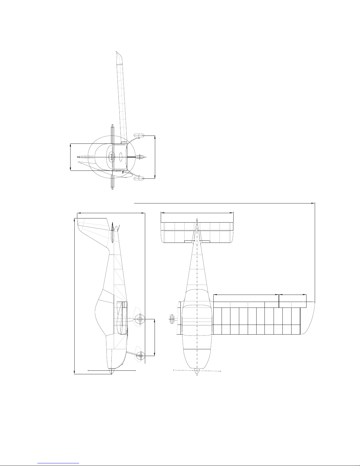
1.4.3 Three-view drawing
8.1 m
26.57 ft
2.5 m
8.2 ft
2
.34
m
7
.7
f
t
19.62 ft
5.98 m
2.25 m
7.38 f t
0.94 m
3.1 ft
4.42 ft
1.35 m
1.6 m
5.25 ft
3.42 ft
1.04 m
POH/EUR/01 Issue 2 Page 8 of 42
SECTION 2 - LIMITATIONS
2.1 Introduction
Section 2 includes operating limitations, instrument markings and basic placards
necessary for the safe operation of the aircraft, its engine, standard systems and
standard equipment.
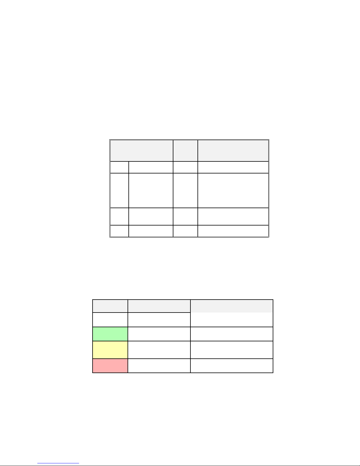
2.2 Airspeed
Airspeed limitations and their operational significances are shown below:
Speed
IAS
mph
Remarks
V
NE
Never exceed
speed
146
Do not exceed this speed in
any operation.
V
A
Manoeuvring
speed
100
Do not make full or abrupt
control movement above
this speed, because under
certain conditions the
aircraft may be overstressed
by full control movement.
V
NO
Maximum
structural
cruising speed
118
Do not exceed this speed
except in smooth air, and then
only with caution.
V
FE
Maximum Flap.
Extending speed
77
Do not exceed this speed with
flaps extended.
2.3 Airspeed indicator markings
Airspeed indicator markings and their colour-code significances are shown
below:
Marking
IAS value or range
mph
Significance
White
arc
40 – 77
Positive Flap Operating Range.
Green
arc
49 – 118
Normal Operating Range.
Yellow
arc
118 – 146
Manoeuvres must be conducted
with caution and only in smooth
air.
Red
line
146
Maximum speed for all operations.
The lower end of the white arc is 1.1 V
SO
The lower end of the green arc is 1.1 V
S1
POH/EUR/01 Issue 2 Page 9 of 42
2.4 Powerplant
Engine Model: ROTAX 912 UL
Engine Manufacturer: Bombardier-Rotax GMBH
Power
Max Take-off: 59.6 kW / 80 hp at 5800 rpm, max.5 minutes
Max.
Continuous:
56 kW / 75 hp at 5200 rpm
Cruising: 53 kW / 71 hp at 4800 rpm
Engine speed
Max. Take-off: 5800 rpm, max. 5 min.
Max.
Continuous:
5200 rpm
Cruising: 4800 rpm
Idling: ~1400 rpm
Cylinder
head
temp.
Minimum 60 °C 140 °F
Maximum 150 °C 302 °F
Oil temp.
Minimum 50 °C 122 °F
Maximum 140 °C 284 °F
Optimum 90 – 110 °C 194 - 230°F
Oil
pressure
Maximum 7,0 bar
Minimum: 1,5 bar
Optimum: 1,5-4,0 bar
Fuel: see 2.13
Fuel Pressure min. 0.15 bar, max. 0.4 bar
Oil: Automotive engine oil of registered brand with gear
additives, but not aircraft oil (refer to engine Operator´s
Manual).
API classification SF or SG.
Propellers and
Manufacturers
V 230C
VZLÚ
Praha,
Czech Republic
GT-2/166/VSR FW101 SRTC
GT Propellers
Riccione
Italy
Types: Two blade fixed
wooden propeller
Two blade fixed wooden
propeller
Propeller diameters: 1625 mm 1660 mm
Propeller pitches: 18°20´ - 18°55´ 1450 mm
WARNING
The Rotax 912 UL has not been certified as an aircraft engine and its failure may occur at
any time. The pilot is fully responsible for consequences of such a failure. Never fly over
an area on to which you cannot safely land in the event of an engine failure.
POH/EUR/01 Issue 2 Page 10 of 42

2.5 Powerplant Instrument Markings
Analogue powerplant instruments are installed in the EV-97 teamEurostar UK
aeroplane, with the following markings:
Minimum
Limit
Normal
Operating
Caution Range Maximum Range
Engine speed (RPM) 1400 1400-5200 5200-5800 5800
POH/EUR/01 Issue 2 Page 11 of 42

Cylinder Head Temperature
(CHT)
60 °C, 140 °F
60-100 °C
140-212 °F
100-150 °C
212-302 °F
150 °C
302 °F
Oil Temperature
50 °C
122 °F
90-110 °C
194-230 °F
50-90 °C, 122-194 °F
110-140 °C, 230-284 °F
140 °C
284 °F
Oil Pressure 1.5 bar
1.5 - 4.0
bar
4.0 - 5.0 bar
7.0 bar
cold engine starting
Fuel Pressure 0.15 bar
0.2 – 0.3
bar
0.3 – 0.4 bar 0.4 bar
2.6 Miscellaneous instrument markings
• Fuel gauge
A fuel reserve of 11 litres (2.42 Imp. gals) is indicated by yellow warning lamp.
2.7 Weight
Empty weight (standard equipment) max. 268 kg 591 lbs
NOTE
Actual empty weight is stated in SECTION 6, par. 6.2
Max. take-off weight 450kg 992 lbs
Max landing weight 450kg 992 lbs
Max. weight of fuel 47kg 104 lbs
Max. baggage weight 15kg 33 lbs
2.8 Centre of Gravity
Empty aircraft C.G. position (standard) 18±2% MAC = 200 – 250 mm AOD
Operating C.G. range 20-34% MAC = 250 – 425 mm AOD
Datum is wing leading edge.
POH/EUR/01 Issue 2 Page 12 of 42
2.9 Approved manoeuvres
Aeroplane Category: Normal; the EV-97 teamEurostar UK aeroplane is approved
for normal and below listed manoeuvres:
• Steep turns not exceeding 60° bank
• Lazy eights
• Chandelles
• Stalls (except whip stalls)
WARNING
Aerobatics and intentional spins are prohibited !
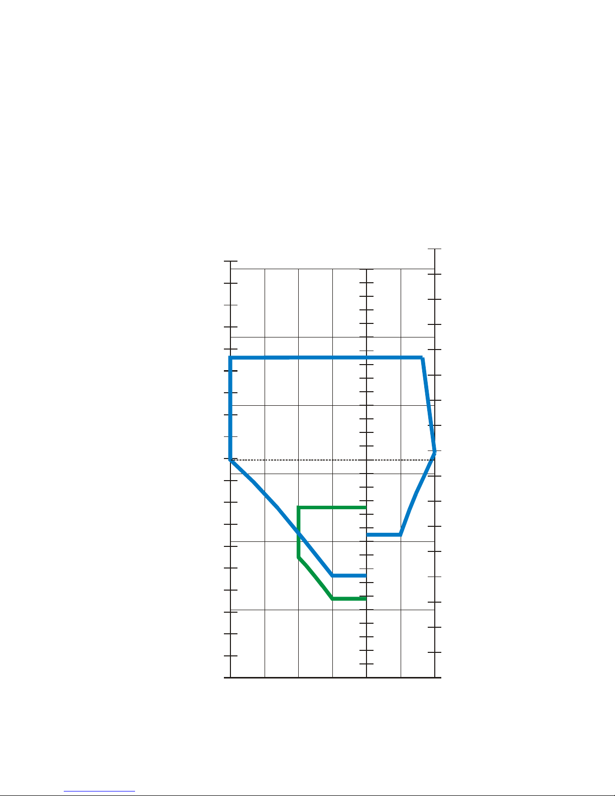
2.10 Manoeuvring Load Factor
POH/EUR/01 Issue 2 Page 13 of 42
LOAD FACTOR [-]
0
10
V
V
V
V
S0
S1
A
NE
20
30
40
50
60
70
80
90
100
110
120
130
140
150
160
170
180
190
200
210
220
230
240
250
260
270
280
290
300
-1
-2
1
2
3
4
0
10
20
30
40
50
60
70
80
90
100
110
120
130
140
150
160
170
180
0
10
20
30
40
50
60
70
80
90
100
110
120
130
140
150
160
170
190
KIAS
IAS [km/h]
IAS [mph]
EV-97 EUROSTAR FLIGHT ENVELOPE
A
G
E
D
 Loading...