

Page 1

River Service
Page 2
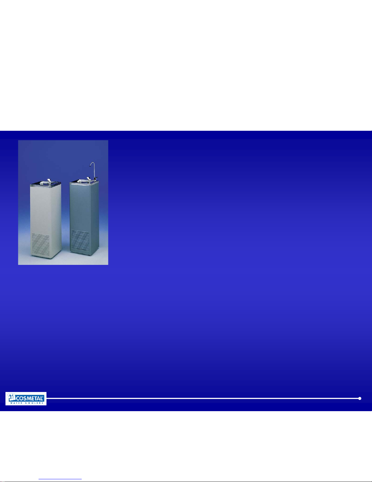
2
River 15
- cold water production (10°C): 15 litres per hour
- compressor: 1/10 HP
- condensation: Static
River 25
- cold water production (10°C): 25 litres per hour
- compressor: 1/6 HP
- condensation: Ventilated
River 50
- cold water production (10°C): 50 litres per hour
- compressor: 1/4 HP
- condensation: Ventilated
Page 3
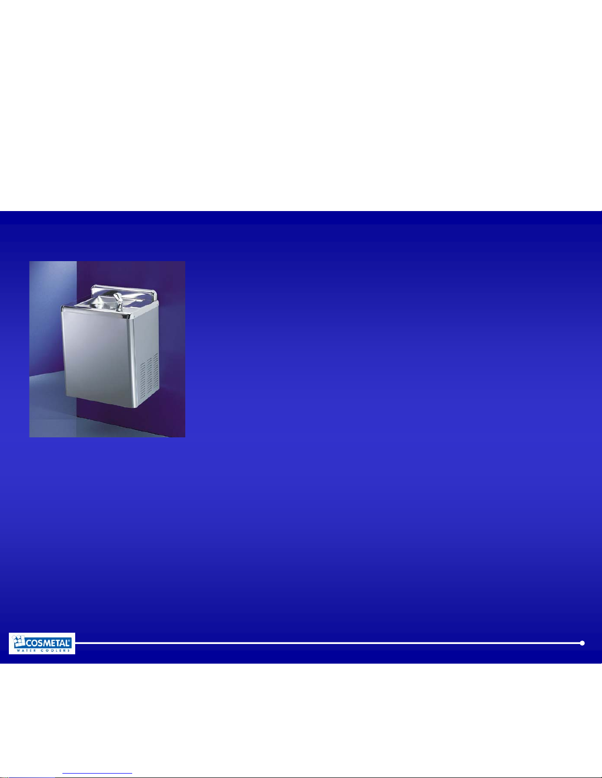
3
River 25 UP
- cold water production (10°C): 25 litres per hour
- compressor: 1/6 HP
- condensation: Ventilated
River 50 UP
- cold water production (10°C): 50 litres per hour
- compressor: 1/4 HP
- condensation: Ventilated
Page 4
4
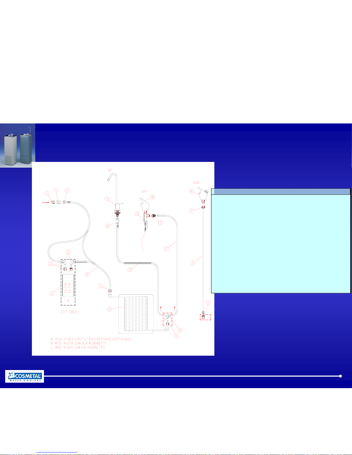
River - Hydraulic Circuit
N. CODICE DESCRIPTION
1
2521412 BULKHEAD CONNECT. NICKEL-PLATED 3/8F-1/2M
2
2521367 EQUAL ELBOW JG 8
3
2521363 STEM ADAPTOR JG 3/8M - 8
4
1501302 EVERPURE FILTER
5
2521360 STRAI GHT ADAPTOR JG 3/8M - 8
6
8150120 6 1 DIRECT COOLING SYSTEM RIVER 15
8110020 1 1 DIRECT COOLING SYSTEM RIVER 25
8110030 1 1 DIRECT COOLING SYSTEM RIVER 50
7
2521375 STRAIGHT ADAPTOR JG 1/8M - 8 FOR G62 TAP
8
2521364 EQUAL TEE JG 8
9
2801363 TUBE 8
10
2521366 STRAIGHT ADAPTOR JG FO R G61 TAP
11
2521705 G61 TAP
14
2521706 G62 TAP
15
2781193 MECHENICAL VALVE FOR G63 TAP
16
2521707 G63 TAP
Page 5

5
Setting up the cooler at your premises
• Examine the packaging for sign of damage, report any damage to
the haulier
• Remove the carton and the plastic bag from the cooler
• Make a general inspection, ensuring that there are no marks or
damage to River and all accessories are present
• Sanitise the cooler
• Replace the plastic bag
• Replace the box over the cooler
• The River is ready for the transportation to the customer
Page 6

6
Installation
• Place the cooler in the desired point of installation, away from
heat sources and protected from direct sunrays.
• Adjust foot to level the cooler correctly and to avoid irritating
noises caused by vibration.
• When handling and moving the cooler, use the handle recessed
into the cross support on the back of the unit.
• To ensure proper ventilation, position the River at a distance of at
least 6-7 cm from the wall.
Page 7
7
Assembly and adjustment of faucets 1
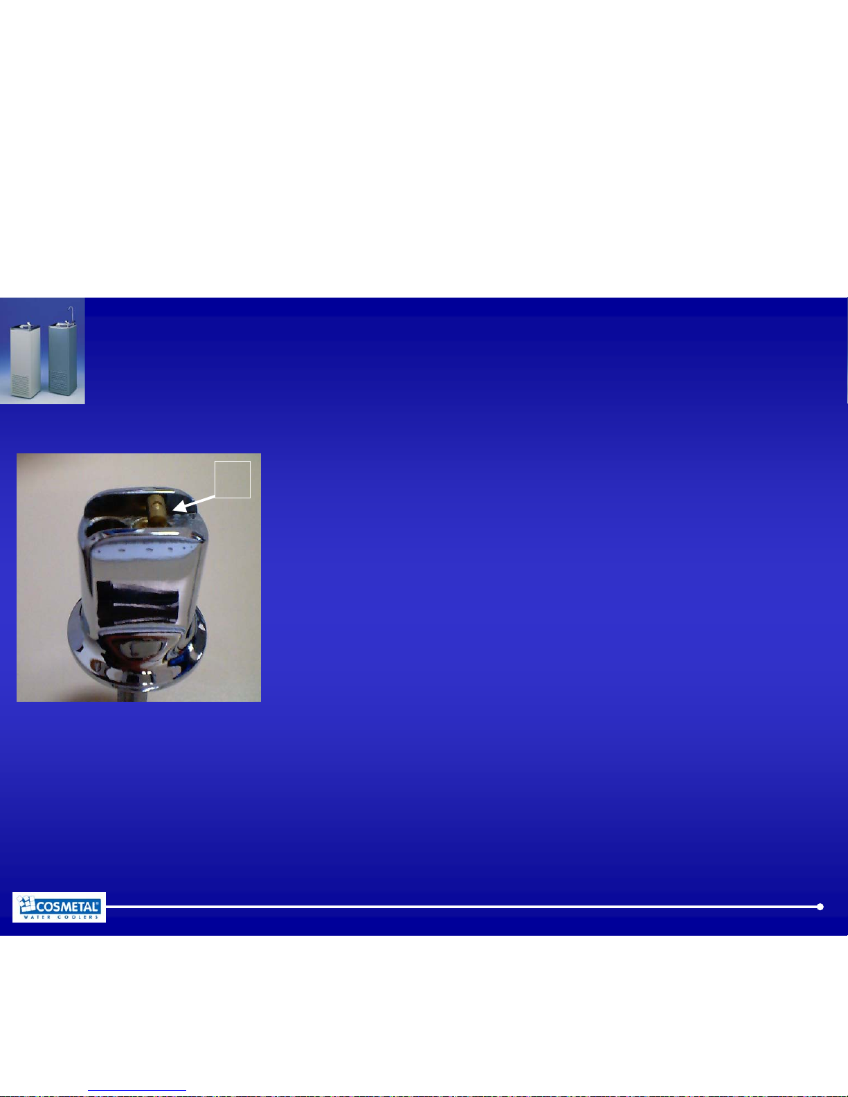
Faucet G61
Insert the lever and let it glide on the specific
guiding channel, attach the tube, and tighten it.
The water flow is pre-set by the manufacturer.
If it needs to be adjusted, manipulate ratchet N,
tighten it to increase the flow, loosen it to decrease
it.
Only carry out one revolution at a time.
N
Page 8
8
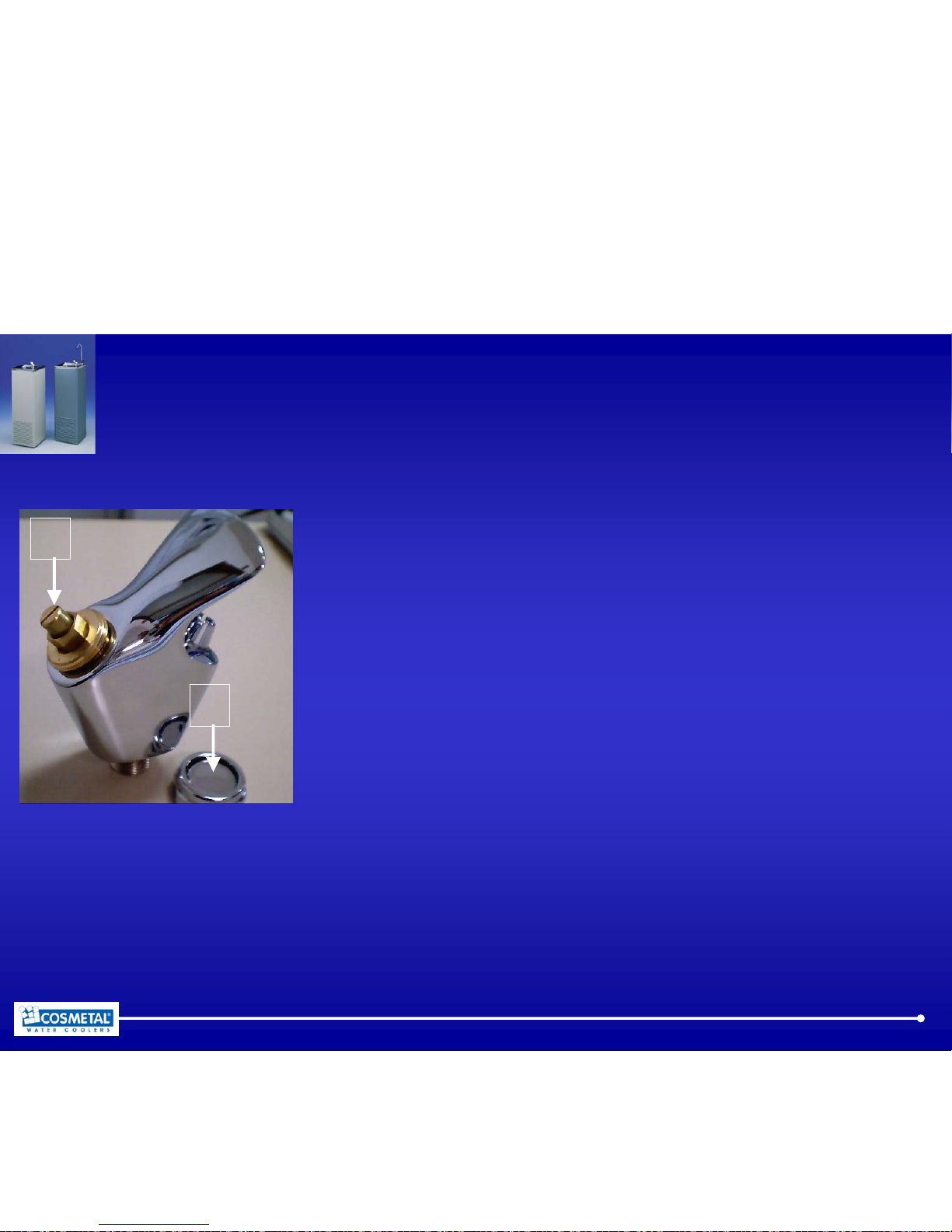
Assembly and adjustment of faucets 2
Faucet G62
The faucets G62 are always assembled.
To regulate the water flow, remove ferrule G and
manipulate screw V.
Turning it clockwise will decrease the flow,
anticlockwise movement will in-crease it.
V
G
Page 9
9
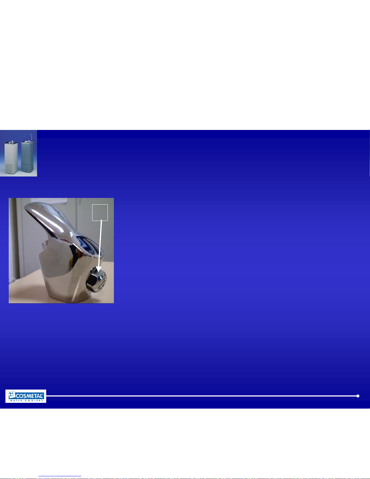
Assembly and adjustment of faucets 3
Faucet G63
The faucets G63 are always assembled.
This faucet is being controlled by a pedal, which
must be attached with a trigger device at the
predetermined location.
The water flow is regulated by manipulating screw S:
turning it clockwise will decrease the flow,
anticlockwise movement will increase it.
S
Page 10

10
Water connection to the mains
• Before making the water connection, make sure the mains water
pressure is between 1 and 3 bars.
• If the mains water pressure exceeds 3 bars, predispose a pressure
reducer capable of reducing the latter to the 1-3 range.
• Connect the appliance to the water mains using the water inlet
fitting.
• The 3/8F connector or the fast coupling provided can be used for
the 8 mm diameter pipe.
• Predispose a stop tap on the water inlet pipe.
Page 11

11
Connection on wastewater tube
• The wastewater is clean. It originates at the basin that collects
possible water drips during the distribution phase.
• Connect the wastewater tube (internal diameter 18 - external
diameter 24 mm) to a siphoned water discharge system.
• If necessary, cut the tube to avoid bending or an interruption of
downward flow.
Page 12

12
Electricity Connection 1
• Connection to the mains electricity supply is carried out by
connecting the plug to a mains socket
• The supply socket must be equipped with an efficient earth plate
and it must be sized for the load of the appliance (see technical
characteristics).
• Make sure that the mains voltage corresponds with what is
specified on the data plate.
• Make sure that there is an omnipolar switch above the socket with
a minimum contact break of 3 mm protected by fuses of suitable
amperage for the absorption of the appliance itself (see technical
characteristics and data plate).
Page 13

13
Electricity Connection 2
• Turn the screw of the cold water regulator to the maximum
position
• The thermostats make the appliance start.
Page 14

14
Hygienic Cleaning
Page 15

15
Hygienic Cleaning 1
• WARNING! Given that the products used for the hygienic cleaning
procedure contain corrosive acidic and alkaline substances,
disposable gloves and protective eyewear should be worn at all
times.
• When performing the hygienic cleaning procedure, please keep to
the product reaction times, sanitising liquid percentages and
quantities of water for rinsing.
• The hygienic cleaning should be performed before installing the
appliance and each time:
- components of the hydraulic cycle are replaced,
- you encounter or suspect there is contamination,
- the appliance is installed.
Page 16

16
Hygienic Cleaning 2
• Warning: If a filtering kit is fitted on the appliance, it should be
excluded from the hygienic cleaning process.
• Preparation of the hygienic cleaning solution, take five litres of
water in a bucket or pan.
• Add to it 5% of hydrogen peroxide 130 volumes; for the dosage,
use a graduated measuring cup or a common syringe.
• N.B.: when using commercial hygienic cleaning solutions, keep to
the instructions provided by the manufacturer and included in the
packaging.
• Using a pump P, connect the appliance water inlet to the bucket
filled with the disinfectant solution.
Page 17

17
Hygienic Cleaning 3
• Start the pump, allowing the disinfectant to enter the appliance,
then turn on the taps to enable the hygienic cleaning solution to
flow throughout the entire hydraulic circuit, right through to the
water dispensing spout.
• Before you run out of disinfectant solution, turn the pump off and
stop the water dispensing.
• Leave the disinfectant solution to act for 20 minutes.
• Reconnect the appliance to the water mains.
• Allow for at least 15 litres of water to flow out of the taps so that
the water system is rinsed thoroughly, before using the appliance
again.
Page 18

18
Troubleshooting
Page 19
19
Troubleshooting cold water system 1
No cold water and compressor not running
1 Check voltage received by cooler
2 Check cold thermostat
3 Check wires
4 Check compressor relay
5 Check compressor overload
6 Check compressor
No cold water and compressor running
1 Check voltage
received by cooler.
2 Check for a refrigerant leak
3 Check capillary line
4 Check compressor
Page 20

20
Troubleshooting cold water system 2
Too much noise coming from the cooler
1 Check for vibration at refrigeration pipes
2 Check for vibration
caused by adjustable feet
Cold water comes out slowly or not at all
1 Check water inlet pressure
2 The water is frozen. Check cold thermostat
3 Check water filter
Page 21

21
Repairs & Solutions
Page 22

22
Voltage
Checking the Voltage
• Is the electric cord plugged in?
Plug in the cooler
• Is the switch controlling the outlet in the OFF position?
Switch ON, verify with an electric appliance if the outlet is good.
For voltage problem the customer must to contact the utility company
Page 23

23
Cold thermostat
On all Cosmetal cooler the cold thermostat is the same.
• Check if it’s in OFF position or set to the minimum
• Check for continuity
Unplug the electric cord, with a ohm meter control the thermostat continuity
If it exists the thermostat is good
• Check the wires connected on its terminals
• For change a thermostat it is important measuring the length of
capillary tube inserted in to the copper tube. In the faulty thermostat
place a piece of masking tape around the capillary tube at the point the
tube enters in the copper tube well.
Page 24

24
Wires
Check the electrical wires
• Is any wire disconnected from terminal?
• Is any terminal loose?
Replace any defective wires, terminal, or connectors
Page 25

25
Relays
The starting relay is located in the compressor electric box
• Check the continuity of the starting relay
With a ohm meter control the thermostat continuity.
If it exists the relay is good
• Check the PTC relay (Rio “RI” P.O.U.)
For to test a PTC relay it’s necessary change it with a known good one
Overload
Overload is a compressor self protection, It is possible to replace a faulty
overload, it’s in the compressor electric box
Page 26

26
Compressor
• The compressor runs but does not cool the water (It may be low
on refrigerant)
• The compressor runs a short time and shuts off, then repeats the
pattern several times (the refrigerant lines may be restricted)
Change the compressor.
A specialised refrigerant repairman may do the substitution.
Page 27

27
Refrigerant leak
• Is refrigerant leaking?
Check the temperature of condenser when the compressor running, if the
condenser is quit warm, there is a refrigerant leaking.
Normally when the compressor running, the condenser temperature is
50-55°C.
A specialised refrigerant repairman may do the service.
Page 28

28
Capillary line
• Visually check to see that lines are not bent
A specialised refrigerant repairman may do the service.
Page 29

29
Vibration
• Is a section of the pipes line vibrating against another cooler part?
Eliminate vibrations by moving tubing away from other cooler parts.
• Is the P.O.U. levelled?
Level the cooler using the adjustable feet.
Page 30

30
Inlet pressure
• Is there a minimum pressure in the main water line?
Verify if there is an hand valve close or some tubes are bent.
• Check the mechanical filter fixed on the inlet metal connection.
Clean the mechanical filter or change it.
Page 31

31
Faucet
• Is some drops of water come trough the water tap?
Some dirty is going to inside the valve. It’s necessary to disassemble the
valve and remove the dirty
Page 32

32
Filters
• Is the water filter obstructed?
Change the filter cartridge
 Loading...