

Page 1
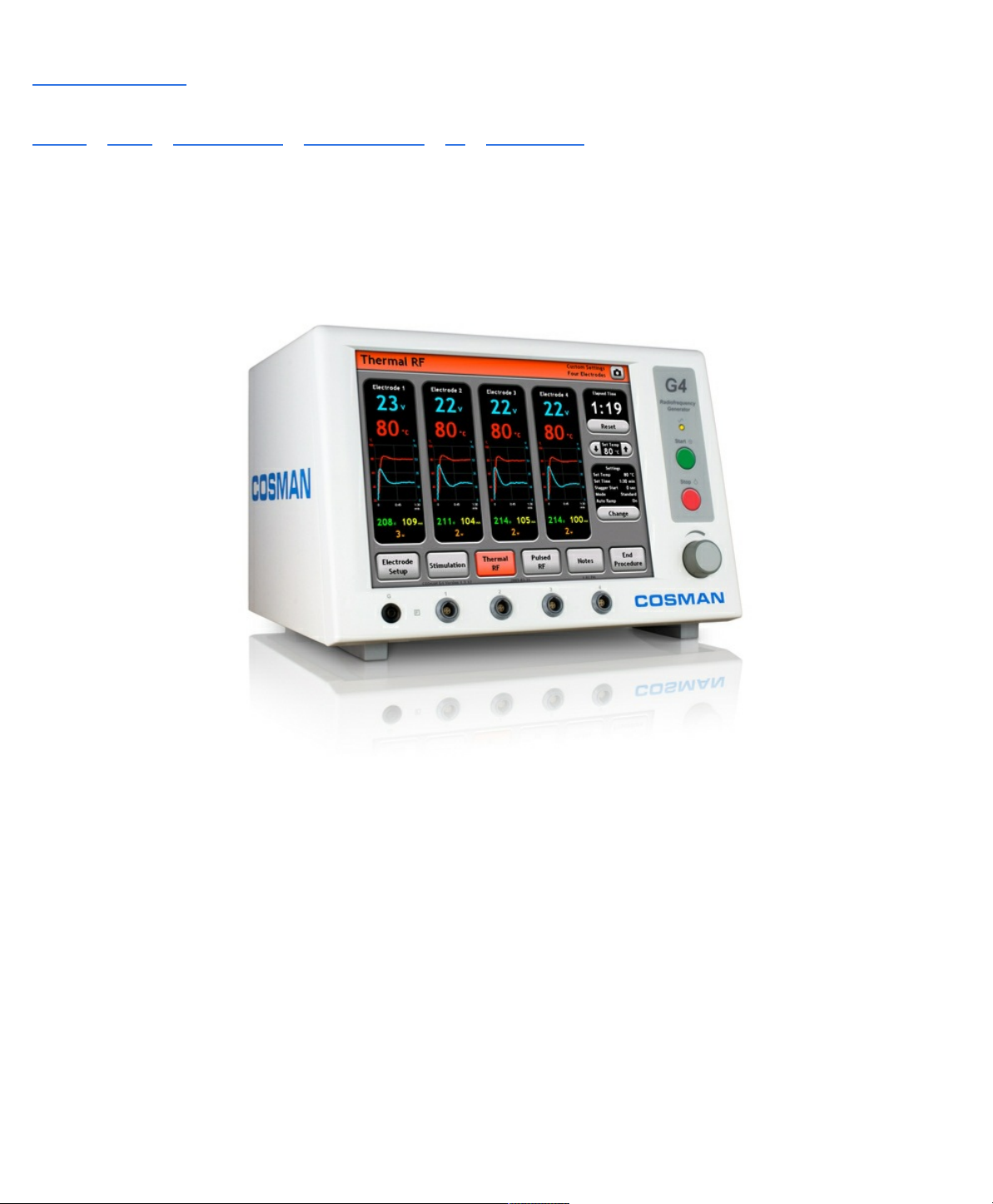
Manuals / Brands / Cosman Manuals / Portable Generator / G4 / Service manual / PDF
COSMAN G4 SERVICE MANUAL
Quick Links
General Information
System Testing
Test Equipment
Page 2

Table of Contents
Sections
General Information
Device Classification
Electrical Safety Information
Key to Device Markings
Mains Power
Output Control
Output Connections
Other Connections
Readings and Indicators
Certifications
Warnings
Unit Identification
Other
Chassis Layout
Front Panel Layout
Back Panel Layout
Getting Started
Indications for Use
Unpacking the G4 System
Turning on the G4 & Main Menu
Start Procedure
Records
System Setup
Startup Screen
Date, Time, Language, and Audio Volume
Page 3

System Setup
Touch Screen Calibration
Testing the G4 Unit
Error and Warning Dialogs
Start Procedure Screen
Modify Preset
Electrode Setup
Electrode Setup Screen
Electrode Setup Settings
Graphing Interface
Stimulation Screen
Additional Example Screens
Stimulation Settings
Control Units
Auto Ramp
Thermal RF Screen
Thermal RF Settings
Mode
Stagger Start
Pulsed RF Screen
Pulsed RF Settings
Max Temperature
One Touch Interface
On-screen Start/Stop button
Stimulation Incremental Controls
Thermal and Pulsed RF Automatic Control
Sterilization, Care, and Service
Troubleshooting
Specifications
Page 4

Electrical supply
Output Power Curves
Output Power ver Knob Setting
Output Power ver Resistance
Accessories
Test Equipment
System Testing
Application Program check
Low voltage Oscillator resonance check
Temperature Display calibration check
High volts measurement calibration
Peak voltage display calibration
Off zero lockout test
Display checks
Lesion timer test
Automatic temperature control
Temperature Variation with cables
Impedance Variation with cables
Impedance range tests
No Temp lock-out test
Audio calibration adjustment
Stimulator tests
Maximum RF output test
Electrical Safety Tests
HIPOT Testing
Leakage Testing
Ground Bond Test
Final check out
System Diagram
Page 5

Backplane Board
Schematic Drawings
Backplane Board Assembly
RMS Stim Board Assembly
Current Board Assembly
USB Card Board Assembly
Power Supply Board Assembly
PC Board Assemblies
Topside part placement
Bottomside part placement
Part lists
Data sheets
Certificate of Conformance
Page 6
DATE
11/7/2008
SUPERSEDES
N/A
STANDARD PROCEDURE INSTRUCTIONS
COSMAN MEDICAL, INC
G4 Service Manual
SPI #
PAGE 1 of 115
DO NOT ISSUE REV
SHEET
ECO # REVISION DESCRIPTION
Eng. Draft 1 Version for initial product release.
Prepared by:____________________________ Date: ____________
11291
REV.
A
Approved by: ___________________________ Date: ____________
Manufacturing
Approved by: ___________________________ Date: ____________
Engineering
Approved by: ___________________________ Date: ____________
Quality and Regulatory Affairs
Approved by: ___________________________ Date: ____________
Management
Page 7

Cosman G4 Radiofrequency Generator Service Manual (SPI 11291 Rev A)
Section 1
Page 8
Cosman G4 Radiofrequency Generator Service Manual (SPI 11291 Rev A)
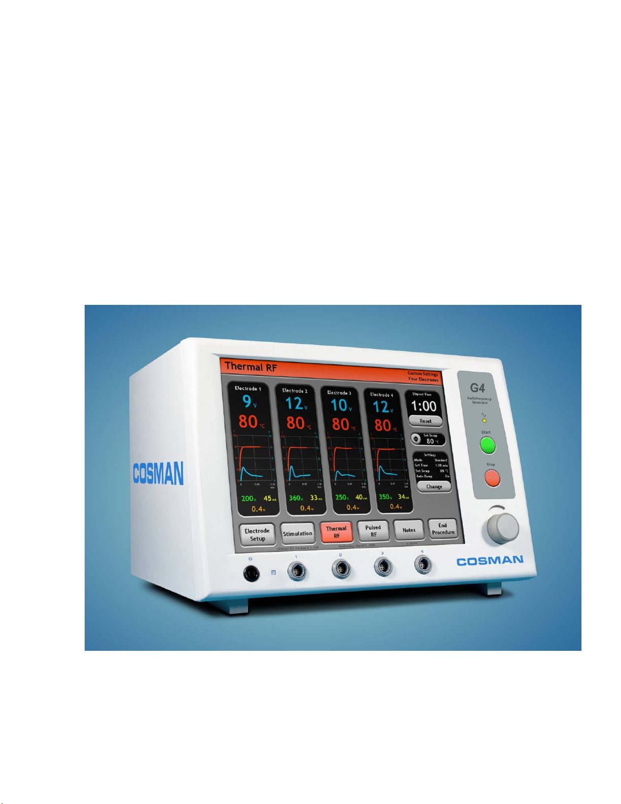
Cosman G4
Radiofrequency Generator
Service Manual
Section 1
Page 9
Cosman G4 Radiofrequency Generator Service Manual (SPI 11291 Rev A)
Title and Publication Number
G4 Service Manual
SPI 11291 Rev. A
Copyright Information
© 2008 by Cosman Medical, Inc., Burlington, Massachusetts, USA.
All rights reserved.
Caution
U.S. Federal law restricts this device to sale by, or on the order of, a physician licensed by the state in which he practices to
use, or order the use of, the device.
Limited Warranty
Cosman Medical, Inc. warrants to the original purchaser that the equipment listed in the Operators’ Manual shall be free from
defects in material and workmanship for a period of 1 year from the date of shipment. Cosman Medical, Inc. obligation under
this warranty shall be limited to repair or replacement, at the option of Cosman Medical, Inc. The above warranty is
contingent upon normal usage and does not cover products that have been modified without Cosman Medical’s approval or
which have been subjected to unusual physical or electrical stress.
Electrodes: Since electrodes are more subject to abuse, the warranty differs from the G4 Generator.
Notices
No part of this document may be reproduced, stored in a retrieval system, or transmitted, in any form or by any means—
electronic, mechanical, photocopying, recording, or otherwise—without the expressed, written consent of Cosman Medical,
Inc. Additional copies of this document can be ordered from Cosman Medical.
Trademarks
G4, Graphics 4, Graphics Four, and RFG-4 are trademarks of Cosman Medical, Inc. All trade names referenced are the
trademarks, registered trademarks, or products of their respective manufacturers.
Manufactured By
Cosman Medical, Inc.
76 Cambridge St.
Burlington MA 01803 USA
Tel: 781-272-6561
Fax: 781-272-6563
Internet Address
www.cosmanmedical.com
EC REP
Neurotechnics Ltd.
8 Manor Park
Banbury OX16 3TB
United Kingdom
FCC Statement Concerning RFI
The G4 generates and uses radio-frequencies. The equipment may cause interference with other medical equipment in the
vicinity. If interference occurs, one or more of the following measures could remedy the problem:
• Move the G4 away from the affected equipment.
• Plug the G4 into a separate outlet so that it is on a different branch circuit.
If necessary, consult the manufacturer of the affected equipment or an experienced technician. In addition, the booklet “How
to Identify and Resolve Radio-TV Interference Problems” may be helpful. This booklet is published by the FCC and is
available from the U.S. Government Printing Office, Washington, D.C., 20402, Stock No. 004-00-00345-4.
Section 1
Page 10

Cosman G4 Radiofrequency Generator Service Manual (SPI 11291 Rev A)
Sections
1. General Information
1.1 Device Classification
1.2 Electrical Safety and EMC
1.3 Electrical Safety Information
1.4 Key to Device Markings
2. Chassis Layout
2.1 Front Panel Layout
2.2 Back Panel Layout
3. Getting Started
3.1 Description
3.2 Indications for Use
3.3 Unpacking the G4 System
4. Turning on the G4 & Main Menu
5. System Setup
5.1 Date, Time, Language, and Audio Volume
5.2 Touch Screen Calibration
5.3 Testing the G4 Unit
5.4 Error and Warning Dialogs
6. Start Procedure Screen
7. Electrode Setup Screen
7.1 Electrode Setup Settings
8. Graphing Interface
8.1 Stimulation Screen
8.2 Thermal RF Screen
8.3 Pulsed RF Screen
9. One Touch Interface
9.1 Stimulation Screen
9.2 Thermal RF Screen
10. Sterilization, Care, and Service
11. Troubleshooting
12. Specifications
13. Output Power Curves
14. Accessories
15. Test Equipment
16. System Testing
16.1 Application Program check
16.2 Low voltage Oscillator resonance check
16.3 Touch Screen Display test
16.4 Temperature Display calibration check
16.5 High volts measurement calibration
16.6 Peak voltage display calibration
16.7 Off zero lockout test
16.8 Display checks
16.9 Lesion timer test
16.10 Automatic temperature control
16.11 Temperature Variation with cables
16.12 Impedance Variation with cables
16.13 Impedance range tests
16.14 No Temp lock-out test
16.15 Audio calibration adjustment
16.16 Stimulator tests
16.17 Maximum RF output test
17. Electrical Safety Tests
17.1 HIPOT Testing
17.2 Leakage Testing
17.3 Ground Bond Test
18. Final check out
19. System Diagram
20. Schematic Drawings
20.1 Backplane Board Assembly
20.2 RMS Stim Board Assembly
20.3 Current Board Assembly
20.4 USB Card Board Assembly
20.5 Power Supply Board Assembly
21. PC Board Assemblies
21.1 Backplane Board Assembly
21.2 RMS Stim Board Assembly
21.3 Current Board Assembly
21.4 USB Card Board Assembly
21.5 Power Supply Board Assembly
22. Part lists
22.1 Backplane Board Assembly
22.2 RMS Stim Board Assembly
22.3 Current Board Assembly
22.4 USB Card Board Assembly
22.5 Power Supply Board Assembly
23. Data sheet
Section 1
Page 11

Cosman G4 Radiofrequency Generator Service Manual (SPI 11291 Rev A)
1. General Information
Safe and effective RF lesioning is dependent not only on equipment design, but also on factors under
control of the operator. Do not attempt to operate the G4 prior to completely reading and
understanding the instructions for use.
WARNING: Electric Shock Hazard
There are no user serviceable parts inside the G4. To avoid
electric shock, return the device to Cosman for servicing.
WARNING: Hazardous Electrical Equipment & Active Implants
This equipment is intended for use by qualified personnel only.
This equipment may damage or interfere with the operation of cardiac
pacemakers and other active implants.
Do not use within 15 feet (4 meters) of a cardiac pacemaker unless proper
cautions have been taken. Before use of the Generator, contact the
pacemaker company to determine whether the pacemaker needs to be
converted to fixed rate pacing during the radiofrequency procedure. When
the pacemaker is in the sensing mode, it may interpret the RF signal as a
heartbeat and may fail to pace the heart.
This equipment has an output which is capable of causing a
physiological effect.
WARNING: Risk of Burns and Fire.
Do not use near conductive materials such as metal bed parts or inner
spring mattresses.
WARNING: Protective Earth Grounding
Grounding reliability can only be achieved when the equipment is
plugged into a receptacle marked “Hospital Grade”. Any
interruption of the Protective Earth conductor will result in a
potential shock hazard which cause injury to patient or operator.
1.1 Device Classification
Classifications as per EN 60601-1, the manufacturer describes the G4 as:
Type of protection against Electric Shock
Degree of protection against Electric Shock
Degree of harmful ingress of water
Mode of Operation
Degree of Safety in the Presence of Flammable
Anesthetic Mixture with Air, Oxygen, or Nitrous
Oxide
1.2 Electrical Safety and EMC
Section 1
Class I
Type BF Defibrillator Protected
IPX0 Ordinary
Continuous use
Not suitable for use
Page 12

Cosman G4 Radiofrequency Generator Service Manual (SPI 11291 Rev A)
A
The G4 has been tested to and meets the requirements of the following Electrical Safety Standards:
EN 60601-1 Medical Electrical Equipment (1990, A1: 1993, A2: 1995, A13: 1996)
EN 60601-2-2 Particular Requirements for the Safety of High Frequency
Surgical Equipment (2006)
The G4 has been tested to and meets the requirements of the following EMC Standards:
EN 60601-1-2 Collateral Standards: Electromagnetic Compatibility (2001, A1: 2004)
The following standards apply:
CISPR 11/FCC Part 15 Group 1, Class A, ISM
IEC 61000-4-2 (2001), 61000-4-3 (2006), 610004-4 (2004), 61000-4-5 (2005)
1.3 Electrical Safety Information
The G4 is a radiofrequency generator designed to produce local tissue heating at the tip of an electrode
by the presence of radio frequency current. Special isolation transformers are imposed between power
lines and internal G4 circuitry, resulting in very low leakage current.
WARNING:
is possible to burn the patient at this site due to high current densities. In all
applications, care should be taken to maximize the surface area of the dispersive
electrode. The dispersive electrode should be reliably attached with its entire area
against the patient’s body and as close to the operating field as possible.
The risk of igniting flammable gases or other materials is inherent in lesioning and cannot be eliminated
by device design. Precautions must be taken to restrict flammable materials and substances from the
electrosurgical site. The use of flammable anesthetics and nitrous oxide and oxygen should be avoided,
unless these agents are suctioned away. Flammable agents used for cleaning or disinfecting should be
allowed to evaporate before the application of RF surgery. There is a risk of flammable solutions
pooling under the patient and in body cavities. Any fluid pooled in these areas should be removed
before the equipment is used. Avoid use of flammable materials, such as gauze or cotton wool when
saturated with oxygen. These materials may be ignited by sparks produced in the normal operation of
the G4.
needle electrode should not be used as the dispersive electrode, as it
Section 1
Page 13

Cosman G4 Radiofrequency Generator Service Manual (SPI 11291 Rev A)
WARNING: Apparent low power output or failure of the equipment to function
correctly at normal settings may indicate faulty application of the dispersive
electrode or failure of an electrical lead. Do not increase power before checking for
obvious defects or misapplication. Effective contact between the patient and the
dispersive electrode must be verified whenever the patient is repositioned after the
initial application of the dispersive electrode.
WARNING: Electromagnetic interference (EMI) produced by the unit during normal
operation may adversely affect the performance of other equipment. The
performance of this device may be adversely affected by other high frequency
surgical devices in close proximity. If a problem occurs, separate the devices.
WARNING: The use and proper placement of dispersive electrodes is a key
element in the safe and effective use of this lesion generator, particularly in the
prevention of burns. Read and follow Cosman’s dispersive electrode instructions for
preparation, placement, surveillance, removal and use of any dispersive electrode.
The use of dispersive electrodes that meet or exceed ANSI/AAMI requirements
(HF18) is recommended.
WARNING: Use the Cosman’s DGP-PM large area dispersive electrode, a large
area gel-pad (with a 110 cm² conductive plate area) or an equivalent gel-pad
dispersive electrode (with at least 110 cm² conductive plate area) to disperse and
return RF current over as large an area as possible, and thus minimize heating
effects at that electrode, and to avoid high current densities and resultant burns in
adjacent tissue.
NOTICE: The ground pad should be placed in close proximity to the lesion site.
WARNING: Observe the dispersive electrode during lesioning for signs of excessive
heating.
WARNING: The long-term risks of creation of RF lesions have not been
established.
WARNING: The generator is capable of delivering a significant amount of output.
Patient or operator injury can result from improper handling of the active electrode
and dispersive electrode, particularly when operating the generator. During energy
delivery, the patient should not be allowed to come in contact with metal parts which
are earthed or which have an appreciable capacitance to earth. The use of
antistatic sheeting is recommended for this purpose. Unshielded leads (active or
return) should be positioned so that they cannot come into contact with the patient
or other leads connected to the patient and so that they do not run parallel to nearby
leads.
WARNING: Electrodes and probes of monitoring, stimulating, and imaging devices
can provide paths for high frequency currents even if they are battery powered,
insulated, or isolated at 60 Hz. The risk of burns can be reduced. But not
eliminated, by placing the electrodes or probes as far away as possible from the
lesion site and from the dispersive electrode. Protective impedances incorporated
into the monitoring leads may further reduce the risk of these burns and permit
continuous monitoring during energy delivery. Needles should not be used as
monitoring electrodes during such procedures.
Section 1
Page 14

Cosman G4 Radiofrequency Generator Service Manual (SPI 11291 Rev A)
WARNING: Potentially hazardous conditions may exist when accessories of similar
connector types are combined. Use only appropriate accessories certified by an
accredited test body.
WARNING: Never proceed in a temperature monitored procedure if the generator
does not read body temperature before you begin delivering RF energy.
WARNING: Raise the temperature slowly, particularly with large electrodes.
Displayed temperature lags behind the actual temperature due to the thermal mass
of the electrode.
WARNING: Verify functional safety of the device before each use, using the
guidelines detailed in this manual.
WARNING: The output of any electrode may change when patient output is being
delivered. Do not move electrode(s) or change electrode connections to the
generator when patient output is being delivered to any electrode.
WARNING: To avoid unanticipated stimulation to the patient, do not cycle the
generator power or turn the generator power on while the patient is connected to the
generator.
NOTICE: Always have spare electrodes and cables on hand in case a problem
arises with the first one during a procedure. Reuseable cables and accessories
should be periodically tested.
NOTICE: Use of DGP-PM ground pad with a stainless steel RF Cannula may
provide a galvanic potential (the “battery effect”) resulting in a single stimulation
pulse at the time the TC Electrode is placed into an RF Cannula. This should be
anticipated, and does not present any risk or danger to the patient.
NOTICE: Always record the wattage readings that correspond to a given
temperature for a given technique. This gives extra guidance and helps Cosman
Medical diagnose problems.
WARNING: Proper electrode placement should be verified using anatomical
landmarks, sensory and motor stimulation techniques, fluoroscopic guidance,
Impedance reading, and good clinical judgment before RF lesion making procedures
are initiated.
Section 1
Page 15
Cosman G4 Radiofrequency Generator Service Manual (SPI 11291 Rev A)
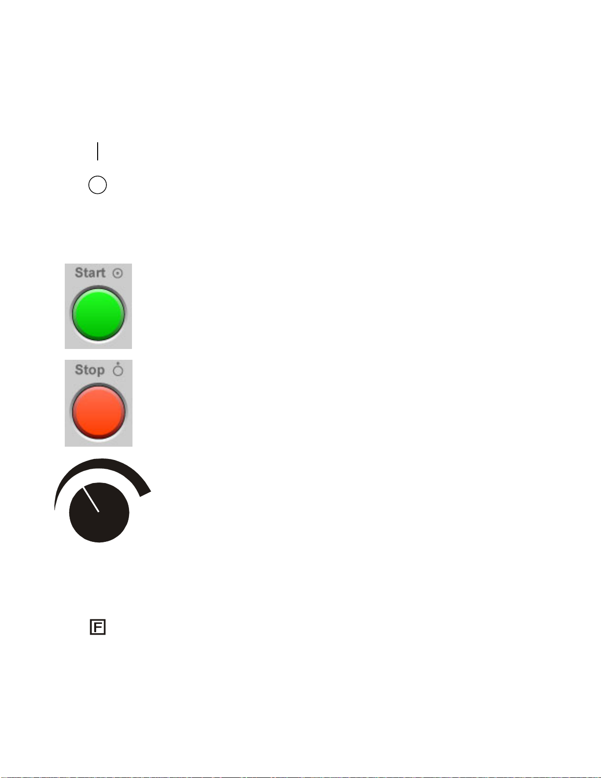
1.4 Key to Device Markings
Mains Power
Output Control
Mains Power On Switch
Main Power Off Switch
Front-panel Start Button (Turn on electrode output)
Front-panel Stop Button (Turn off electrode output)
Output Control Knob
Output Connections
Reference Ground Pad Connection and all RF Electrode
Output Connections isolated at low and high leakage
currents
G
1
Reference Ground Pad Connection (on front panel)
RF Electrode Output Connection 1 (on front panel)
Section 1
Page 16
Cosman G4 Radiofrequency Generator Service Manual (SPI 11291 Rev A)
2
3
4
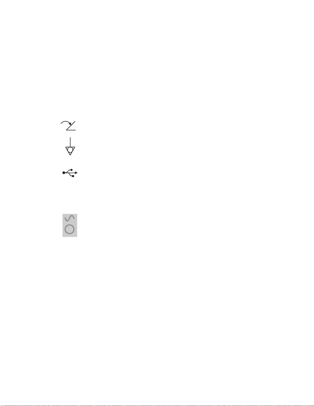
Other Connections
RF Electrode Output Connection 2 (on front panel)
RF Electrode Output Connection 3 (on front panel)
RF Electrode Output Connection 4 (on front panel)
Footswitch Remote Control Connection
Equipotential Jack Terminal
USB Connection (Printer or Memory Stick)
Readings and Indicators
°C
Ω
V
mA
W
ms
Hz
Output On Indicator Light
Temperature (Degrees Celsius)
Impedance (Ohms)
Voltage (Volts)
Current (Milliamps)
Power (Watts)
Pulse Duration/Width (millisecons)
Pulse Rate/Frequency (Hertz = 1/Seconds)
min
Time (Minutes:Seconds)
Section 1
Page 17
Cosman G4 Radiofrequency Generator Service Manual (SPI 11291 Rev A)
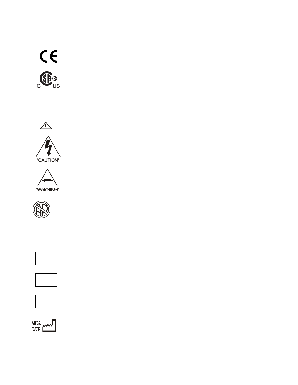
Certifications
Warnings
Unit is compliant with the European Council Directive
93/42/EEC , Medical Device Directive
Unit is approved by CSA to the US standard
Warning: Consult Operator’s Manual.
Warning: Dangerous Voltage. No user-serviceable parts
inside.
Fuse Warning: Replace as marked. Fire Hazard.
DANGER
Unit Identification
REF
LOT
SN
Explosion risk if used with flammable anesthetics.
Reorder Number / Catalog Number
Lot number
Serial Number
Date of Manufacture
Section 1
Page 18
Other
Cosman G4 Radiofrequency Generator Service Manual (SPI 11291 Rev A)
~
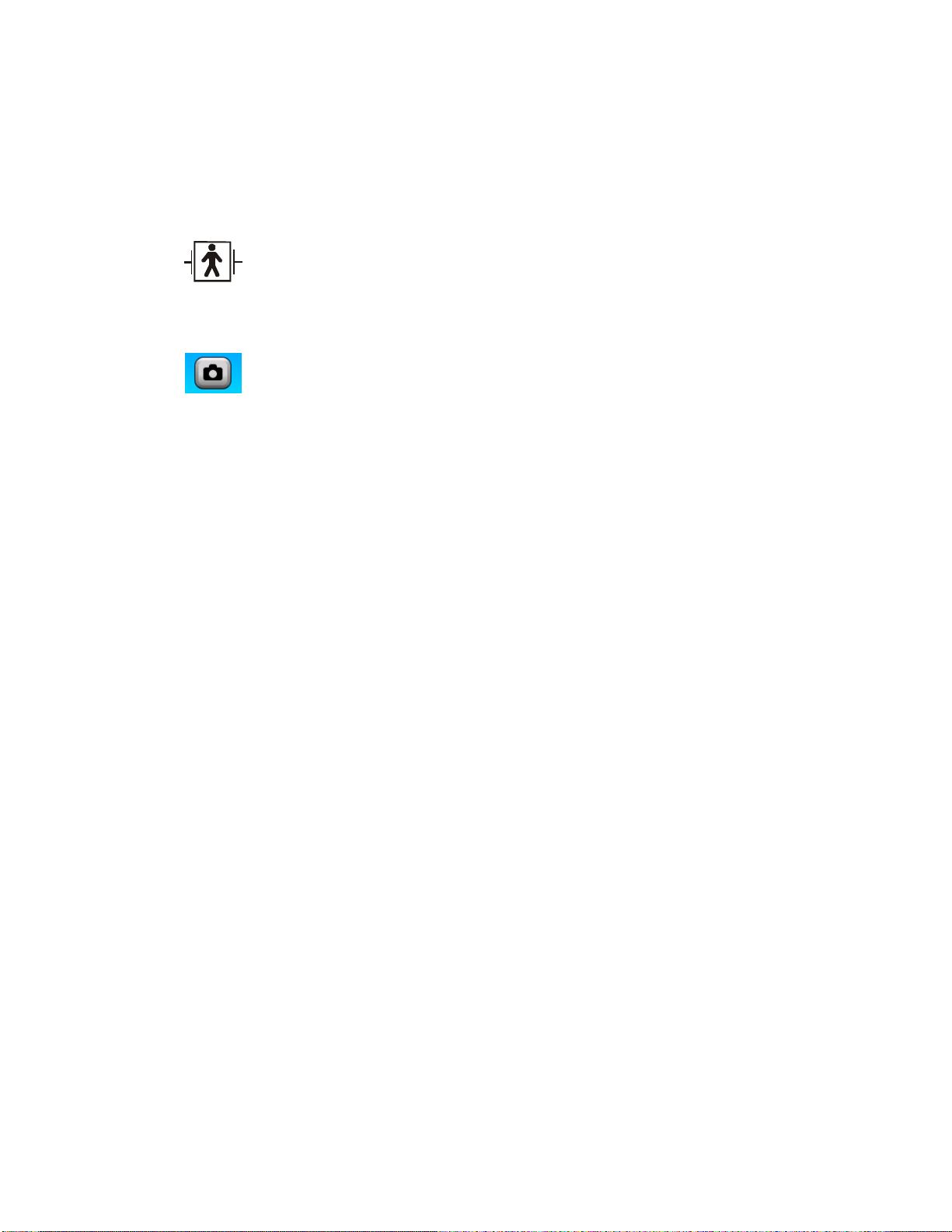
IPX0 Protection against ingression of water: Ordinary
Type BF protection against electric shock. Floating or
isolated applied part/defibrillator protected.
Alternating current (AC)
Screen Shot: Save image of screen to Procedure Record
Section 1
Page 19

Cosman G4 Radiofrequency Generator Service Manual (SPI 11291 Rev A)
r
p
2. Chassis Layout
2.1 Front Panel Layout
Touch Screen
Reference Ground
Pad Connection (G)
Electrode Output
Connection 1
Electrode Output
Connection 2
Electrode Output
Connection 3
Electrode Output
Connection 4
Output On Indicato
Illuminated when any
electrode out
Front-panel Start Button:
Turn on electrode output
when the Stimulation (Sec.
8.1 & 9.1), Thermal RF
(Sec. 8.2 & 9.2), or Pulsed
RF (Sec. 8.3 & 0) screens
are displayed.
Front-panel Stop Button:
Turn off electrode output
Output Control Knob:
Manual output ramping.
Disabled in some modes.
Adjustable
Feet
:
ut is on
Notes:
• Electrode connections are made by attaching a CB112-TC cable to an “Electrode Output
Connection” jack (gray) shown above.
• Patient “Reference” connection is made by attaching a CB103-B black cable or the DGP-PM Ground
Pad to the “Reference Ground Pad Connection” jack (black) shown above.
Section 2
Page 20
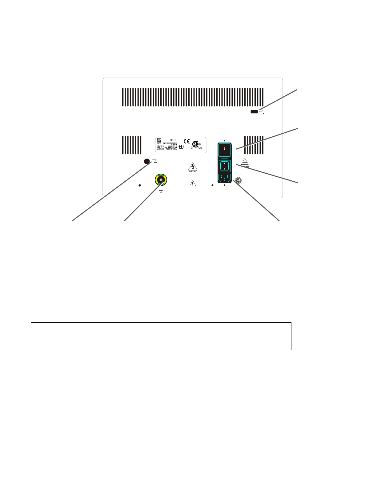
2.2 Back Panel Layout
Footswitch
Connection
Equipotential
Connection
Cosman G4 Radiofrequency Generator Service Manual (SPI 11291 Rev A)
USB Connection: A
printer or external USB
disk.
Fuse box and Mains AC
Voltage Selection:
RFG-4
COSMAN
MEDICAL
, INC.
Burlington, MA 01803 USA
Electric Shock Hazard
DO NOT REMOVE COVERS
No User Serviceabl e Parts
RISK OF FIRE.
REPLACE FUSE AS MARKED.
T2AL250V
100/120/220/240VAC ~50/60 Hz
DANGER
Explosion risk if used with
flammable anesthetics.
Risque D’Explosion. Ne Pas
employer en presence
d’anesthesiques inflammables.
Mains AC Power
Cord Connection
• 100 Vac
• 120 Vac
• 220 Vac
• 240 Vac
Mains Power Switch
ttach
Notes:
• Footswitch Connection: If the optional Footswitch is connected it will function as the Start button
when pressed and the Stop button when released in Stimulation, Thermal RF, and Pulsed RF
modes. All other functions of the unit remain the same.
• Equipotential Connection: This connection may be used to tie the chassis ground of different pieces
of equipment together.
WARNING: When connecting any non-medical peripheral equipment to this device,
it must be ensured that the equipment combination meets the requirements of
IEC 60601-1-1.
Section 2
Page 21
Cosman G4 Radiofrequency Generator Service Manual (SPI 11291 Rev A)
g
3. Getting Started
3.1 Description
The G4 is a lesion generator capable of supplying up to 50 watts of radiofrequency power while
continuously monitoring both the tissue impedance and the temperature at the tip of the one, two, three, or
four electrodes. All of these functions are described in more detail in subsequent chapters.
3.2 Indications for Use
The Cosman G4 Radiofrequency Generator is indicated for use in procedures to create radiofrequency
lesions for the treatment of pain, or for lesioning nerve tissue for functional neurosurgical procedures. The
Cosman G4 Radiofrequency Generator is used with separately approved Cosman Radiofrequency Probes.
3.3 Unpacking the G4 System
G4 Box Contains:
G4 RF Lesion Generator
C119 Power Cord, Domestic (120 V) or
C118 Power Cord, International (220 V)
CB112-TC Connecting Cable for Electrodes
RFG-TP Test Plug
Operator’s Manual
NOTICE: Place the Operator’s Manual in a safe place for later reference.
NOTICE: Save packaging materials for use in the event that the Generator is
shipped back to Cosman Medical, Inc.
4. Turning on the G4 & Main Menu
1. After unpacking the G4 from the shipping box, plug the power cord into the rear of the unit.
CAUTION: Make sure that the wall outlet voltage matches the voltage displayed on
the Voltage Selector located on the rear of unit (100, 120, 220, or 240). If not, open
the Fuse drawer, remove the Voltage Selector and rotate it to the proper voltage
setting.
2. Plug the power cord into the proper AC receptacle. Rotate the G4’s adjustable feet (Section 2.1)
downward change the viewing angle of the front panel.
CAUTION: Disconnect all electrodes, ground pad, and associated cables from the
G4 before turnin
3. Press the Main Power On Switch on the back panel of the generator (Section 2.2). The startup
screen appears in approximately 2 seconds, and it is displayed for approximately 15 seconds.
the mains power on or off.
Section 3
Page 22
Cosman G4 Radiofrequency Generator Service Manual (SPI 11291 Rev A)
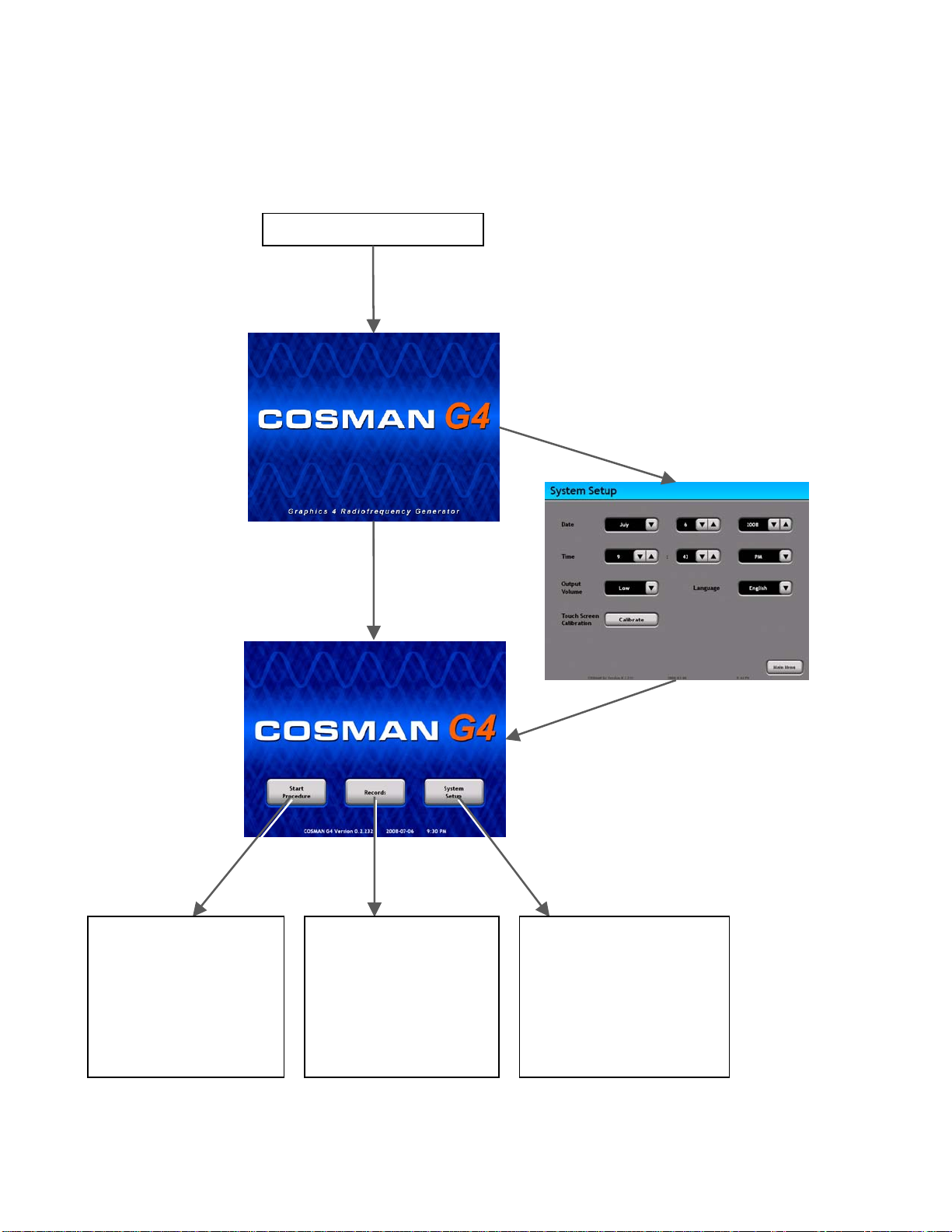
4. If the Time and Date is set, the Main Menu screen is displayed. If the Time and Date is not set, the
System Setup screen is displayed and the Time and Date must be set (Section 5.1).
Generator Mains Power is Off
Press Mains Power On Switch on
back panel of generator (Section
2.2). Wait for 2 sec delay.
Startup
Screen
Main
Menu
If Time
D t
ate previously se
(15 sec delay)
If Time & Date not set
(15 sec delay)
System
Setup
Section 5
Set Time and Date
Start
Procedure
Start Procedure
Section 6
• Load or Modify Personal
Settings Presets
• Produce Stimulation,
Thermal RF, or Pulsed
RF output.
Records
Records
• Review, Edit, Print,
Export, or Delete
Procedure Records
saved on the generator
System
Setup
System Setup
Section 5
• Set Time and Date
• Adjust Audio Volume
• Change Language
• Calibrate Touch Screen
Section 4
Page 23
Cosman G4 Radiofrequency Generator Service Manual (SPI 11291 Rev A)
•
Sy
5. System Setup
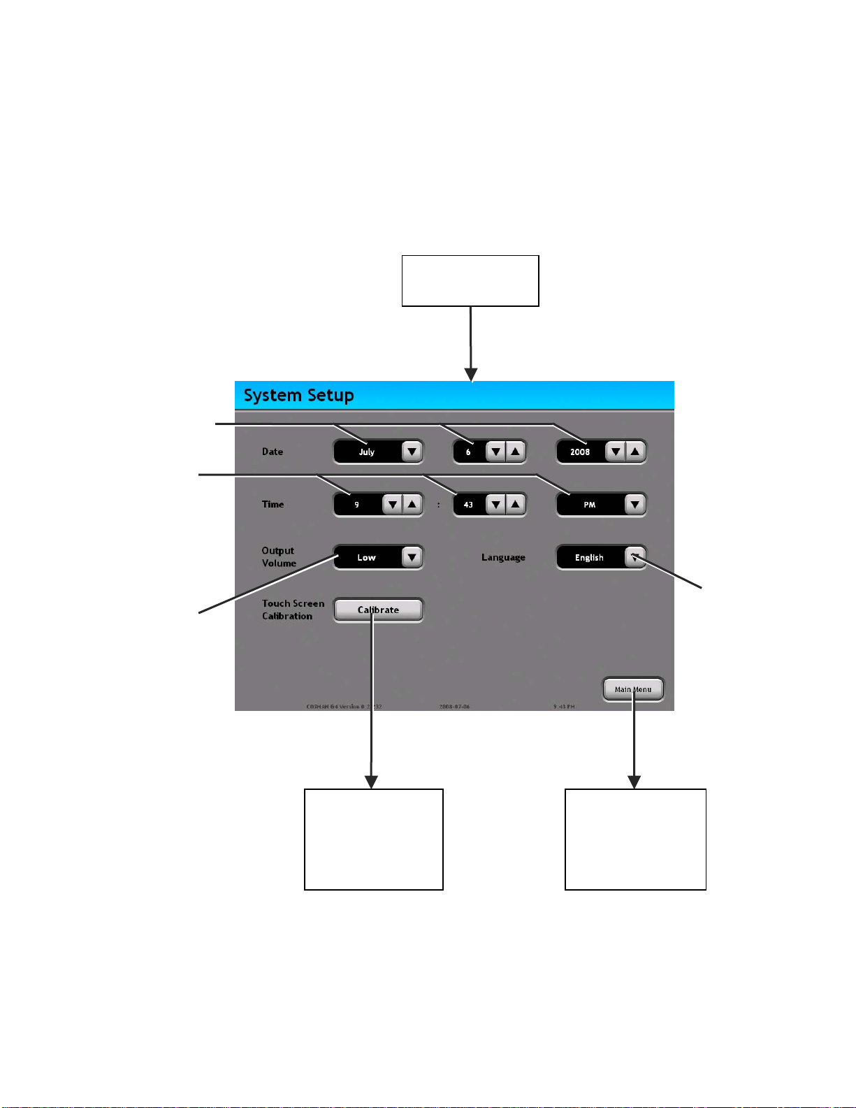
5.1 Date, Time, Language, and Audio Volume
Main Menu
Section 4
Press
"Calibrate"
Set Date
(Month, Day, Year)
Set Time
(Hour, Minute, AM/PM)
Change Audio
Volume
Press
“Calibrate”
Touch Screen
Calibration
Section 5.2
Change
Language
Press
“Main Menu”
Main Menu
Section 4
• Start Procedure
• Records
stem Setup
Section 5
Page 24
Cosman G4 Radiofrequency Generator Service Manual (SPI 11291 Rev A)
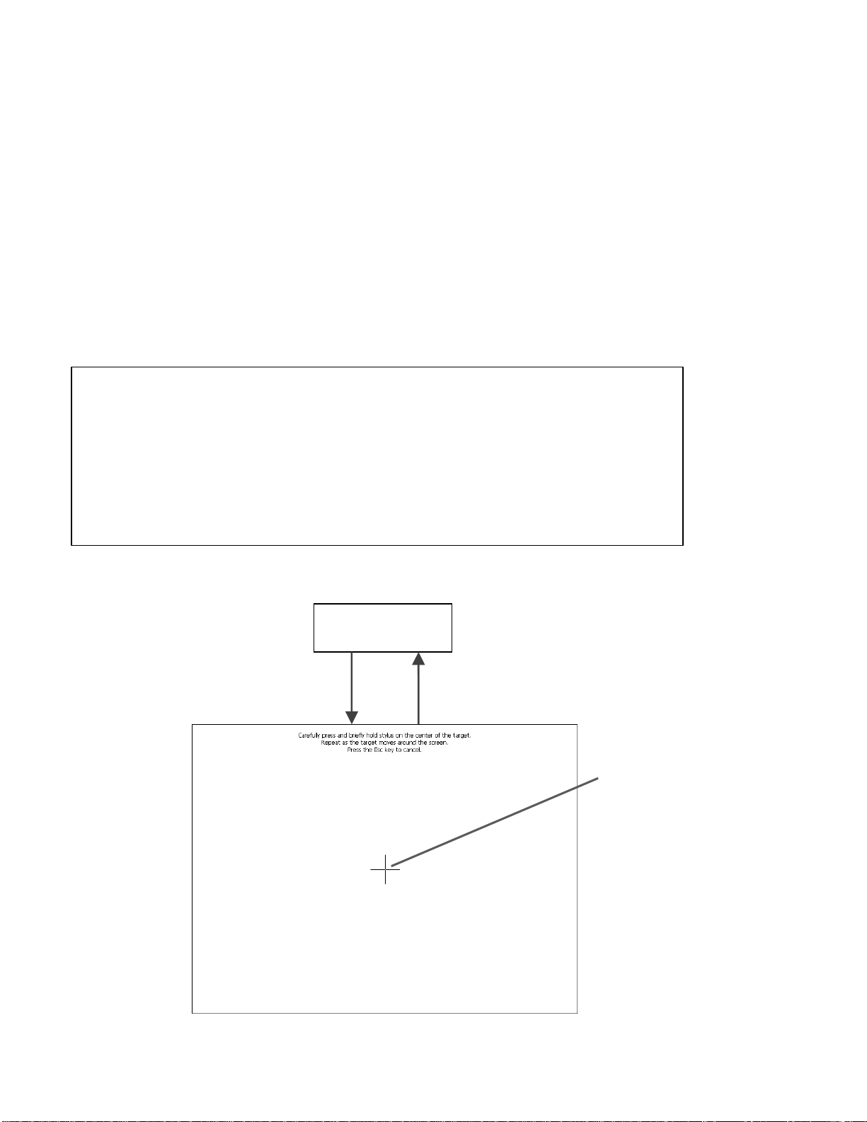
5.2 Touch Screen Calibration
1. Carefully press and briefly hold the center of each cross-shaped target. Lift your finger or stylus
from the screen and repeat when the target moves. Lift your finger from the screen when the target
disappears.
2. When the cross symbol disappears, press anywhere on the screen to return to the System Setup
screen (Section 5.1).
3. Before enabling any generator output, verify the calibration by pressing on-screen buttons that
appear in a variety of locations across the screen. For instance, press each button or drop-down
menu, except the “Calibrate” button, on the System Setup and Main Menu screens. For each tested
button, confirm that a button press is recognized if and only if the screen is pressed within the visible
border of that button. If this test fails for any tested button, repeat the touch screen calibration.
WARNING: Poor calibration of the touch screen may cause user input to be
recognized incorrectly.
NOTICE: Light use of a blunt, plastic stylus (such as that from a touch-screen PDA)
to precisely target the cross symbols may improve touch screen calibration. Damage
to the touch screen could occur if too much pressure is applied or if a sharp object is
used to touch the screen.
NOTICE: Ignore the text “Press the Esc key to cancel”. Touch screen calibration
cannot be canceled.
Calibration
Screen
System Setup
Section 5.1
Press
"Calibrate"
Calibration
Complete
Target
Center
Section 5
Page 25

Cosman G4 Radiofrequency Generator Service Manual (SPI 11291 Rev A)
5.3 Testing the G4 Unit
The ability of the generator to produce RF output and to measure Temperature and Impedance can be
tested by attaching one or more Test Plugs (RFG-TP) to active electrode jacks and performing a procedure.
When a Test Plug is attached to an active electrode jack and the output is off, check that the displayed
Impedance is approximately 100 and the displayed Temperature is approximately room Temperature.
Section 5
Page 26
Cosman G4 Radiofrequency Generator Service Manual (SPI 11291 Rev A)
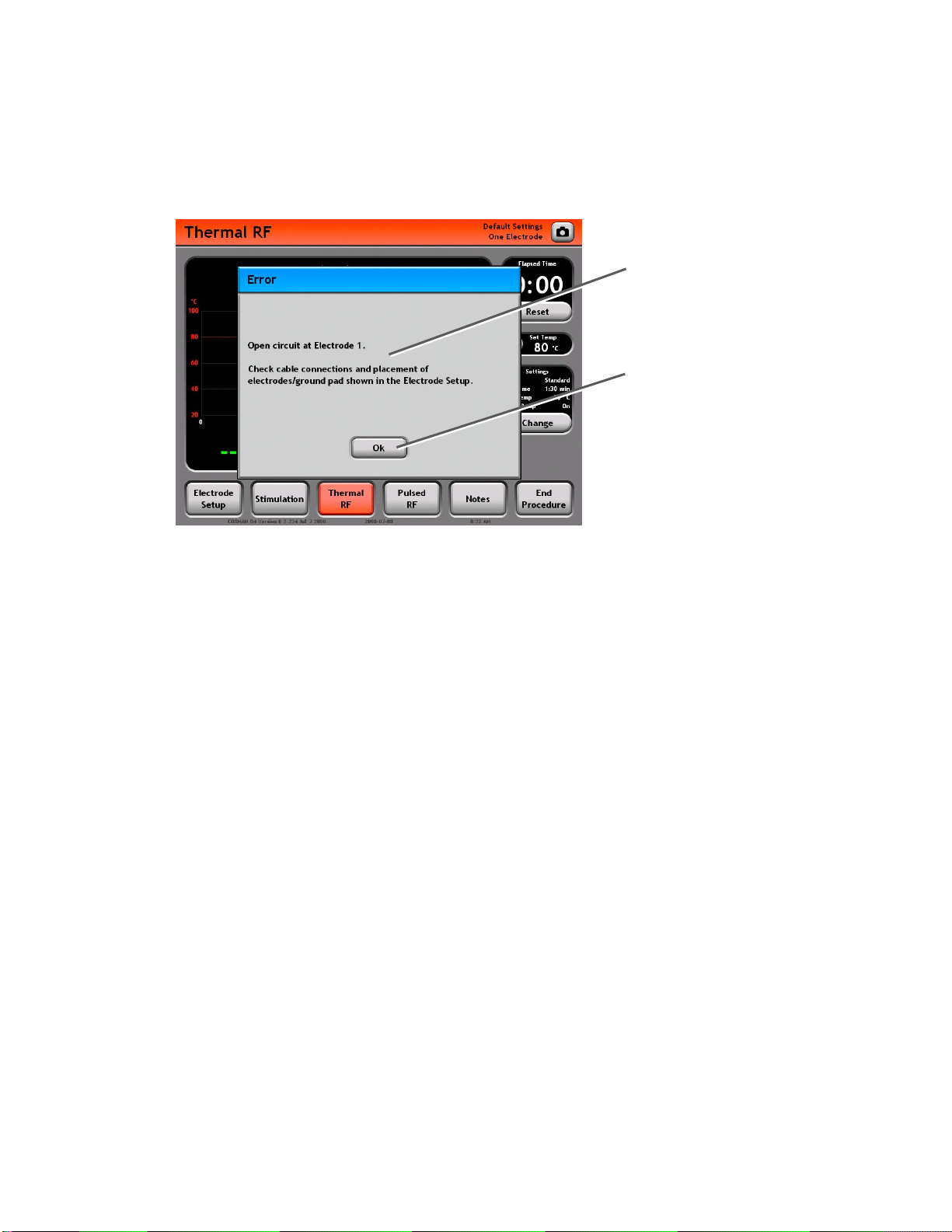
5.4 Error and Warning Dialogs
The generator will alert the user with a dialog box when error conditions occur or for other notification
purposes. Display of an error dialog box is accompanied by an audible error tone, and the user is prompted
Error or Warning Message:
Describes an error condition
that has occurred, or describes
the function of the available
Dialog Box Buttons.
Dialog Box Button: The action o
these buttons should always be
considered in the context of the
Error or Warning Message. For
example:
• Ok: Perform the described
action, or acknowledge the
error/warning message.
• Cancel: Do not perform the
listed action.
f
to acknowledge the error condition by pressing a button in the error dialog box. An example of a dialog box
is shown below.
Common error conditions include the following. See the Troubleshooting guide (Section 11) for more
information.
• Open Circuit: Impedance from Electrode to Reference > 3000
• Short Circuit: Impedance from Electrode to Reference < 30
• No Temperature: No temperature reading from an Electrode
• Low Temperature: Electrode Temp < 10 °C
• High Temperature: Electrode Temp > 100 °C
• Over Temperature: Electrode Temp > TRF Set Temp or PRF Max Temp
• Disconnect Electrode: Electrodes attached to generator do not match current Electrode Setup
settings (Section 7.1).
• High Current/Power: Current or Power output exceeds limits.
Section 5
Page 27
Cosman G4 Radiofrequency Generator Service Manual (SPI 11291 Rev A)
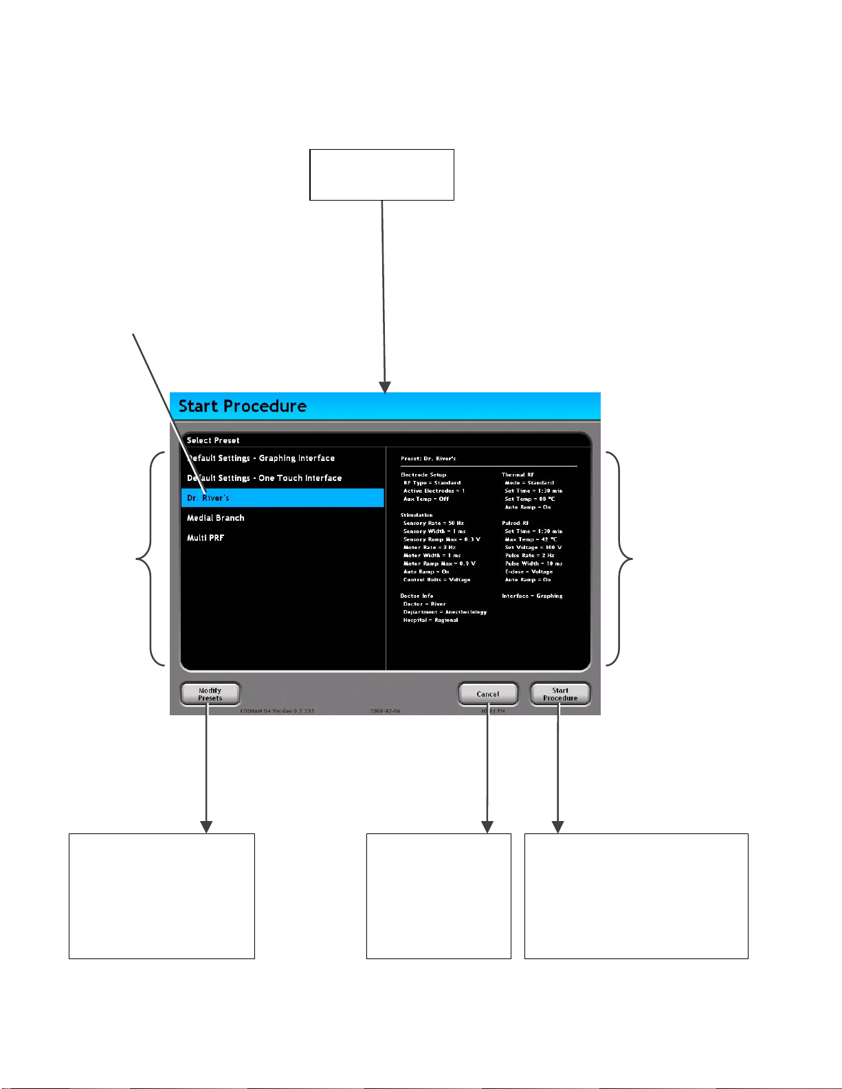
6. Start Procedure Screen
Main Menu
Section 4
Press "Start
Procedure” on
Selected Personal
Settings Preset
Personal Settings
Presets: The
selected Preset will
determine the initial
procedure settings,
including Doctor
Information. These
settings can be
changed at any time
during the procedure.
The Preset also
determines the User
Interface (Graphing:
Section 8 or One
Touch: Section 9.),
which cannot be
changed during a
procedure. Default
Settings Presets for
the Graphing and
One Touch i
are always available,
in addition to userdetermined ones.
nterfaces
Press
"Modify
Presets”
Main Menu
screen
Cancel Button:
Procedure is not
started. Return to
Main Menu.
Preset Summary:
Shows all settings
values for the selected
Preset. These will be
loaded when “Start
Procedure” is pressed.
• Electrode Setup
• Stimulation settings
• Thermal RF settings
• Pulsed RF settings
• Doctor Information
• User Interface
(Graphing: Section 8
or One Touch:
Section 9)
Start Procedure Button: The
selected Preset is loaded and a
new procedure is started. A
Procedure Record is created to
save settings and readings from
the procedure.
Modify Preset
• Edit, Rename, Delete
existing Presets
• Create new Presets
Main Menu
Section 4
• Start Procedure
• Records
• System Setup
Section 6
Electrode Setup
Section 7
• Configure and label electrodes
• Perform procedure using
Stimulation, Thermal RF, Pulsed
RF, and Notes screens.
Page 28
Cosman G4 Radiofrequency Generator Service Manual (SPI 11291 Rev A)
A
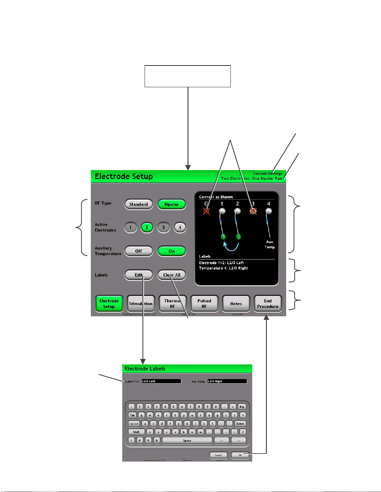
7. Electrode Setup Screen
Settings Buttons:
Buttons highlighted
in green determine
the Electrode Setup
that applies to the
Stimulation,
Thermal RF, and
Pulsed RF screen.
These settings are
described in Section
7.1.
Start Procedure
Section 6
Disconnect electrodes and
probe from any output
connector shown on the screen
marked with a red “X”.
Current Personal
Settings Preset
Current Electrode Setup
Settings Graphic:
Shows the current
Electrode Setup settings.
ttach electrodes, and
ground pad to the
Electrode output
connections on the front
panel (Section 2.1) as
shown on the screen.
Edit Button: Launches a
keyboard to edit labels for the
active electrode
Label Text: A labels can be
assigned to each electrode,
or bipolar electrode pair.
Electrode Labels
Keyboard screen
Clear All Button:
Erases all electrode
labels
Labels: Lists the current
electrode labels.
Mode Bar: Access
other procedure
screens:
• Electrode Setup
(Section 7)
• Stimulation
(Sec. 8.1 & 9.1)
• Thermal RF
(Sec. 8.2 & 9.2
• Pulsed RF
(Sec. 8.3 & 0)
• Notes
• End Procedure
Press “Ok”: Accept
entered text
Press “Cancel”:
Discard entered text
Section 7
Page 29
Cosman G4 Radiofrequency Generator Service Manual (SPI 11291 Rev A)
7.1 Electrode Setup Settings
The Electrode Setup settings determine which electrode output connections (Section 2.1) are to be
delivered Stimulation, Thermal RF, and/or Pulsed RF output.
• RF Type: This setting determines the polarity of active electrode output connections.
• Standard: (a.k.a. "Monopolar") A Reference Ground Pad must be used for return Currents from
active electrodes flow into Reference Ground Pad Connection (G).
• Bipolar: Return Currents flow from active electrode output connections into other active
electrode output connections. Connections 2 and 3 are at reference potential in this
configuration. Voltage, Current, and Impedance readings are displayed for “Bipolar Pairs” of
electrodes, i.e. “Electrode 1+2” and “Electrode 3+4”, of which one is at reference potential and
the other is at potential indicated by the displayed Voltage reading.
• Active Electrodes: The number of electrode output connections to which active electrodes should
be attached.
• Labels: Text may be assigned to each electrode if RF Type = Standard, and to each bipolar
electrode pair if RF Type = Bipolar. Labels are displayed on the Stimulation, Thermal RF, and
Pulsed RF screens, and are logged to the Summary Record.
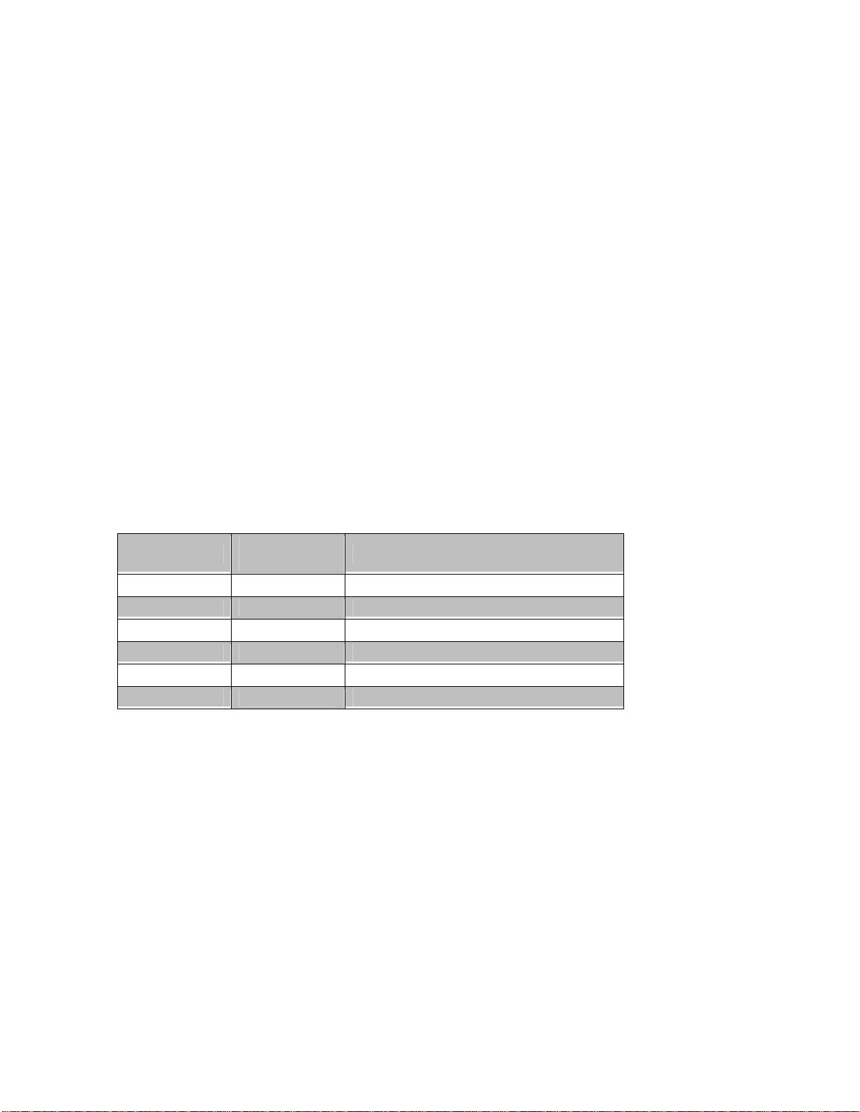
The current Electrode Setup settings are indicated using the following labeling in the upper-right corner of
the Stimulation, Thermal RF, Pulsed RF, and Notes screens, as well as in the Summary Record.
RF Type
Standard 1 One Electrode
Standard 2 Two Electrodes
Standard 3 Three Electrodes
Standard 4 Four Electrodes
Bipolar 2 Two Electrodes: One Bipolar Pair
Bipolar 4 Four Electrodes: Two Bipolar Pairs
Active
Electrodes
Electrode Setup Indicator
Section 7
Page 30
Cosman G4 Radiofrequency Generator Service Manual (SPI 11291 Rev A)
r
p
8. Graphing Interface
The Graphing interface is one of two user interfaces available for operation of the generator in Stimulation,
Thermal RF, and Pulsed RF modes. The other is One Touch interface (Section 9). Choice of user interface
is primarily a matter of user preference, since almost all generator functions (including full automatic ramp
and temperature control) are available in both interfaces. The Graphing interface has the following
distinguishing characteristics.
• Graphing: In Stimulation mode, the output level is plotted as a bar graph (see Section 8.1). In
Thermal and Pulsed RF modes, Voltage and Temperature are plotted a function of time when RF
output is enabled (see Sections 8.2 and 8.3).
• Stimulation Level Annotation: The user can manually mark Stimulation levels (see "Mark Level"
button in Section 8.1) for review in the Procedure Record.
• RF Timer Reset: The Thermal and Pulsed RF timer can be manually reset when output is on (see
Timer, Sections 8.2 & 8.3).
• Manual Thermal RF Temperature Increment: The target Temperature (see "Set Temp Panel",
Section 8.2) for Thermal RF mode can be increased manually in 5°C steps when electrode output is
on.
• Manual Output Control: When the “Auto Ramp” setting is Off (see Sections 8.1.2, 8.2.2 & 8.3.2),
the Stimulation, Thermal RF, and Pulsed RF output levels can be controlled with the Output Control
Knob. Auto Ramp can be disabled in the One Touch interface (Section 9) only if Automatic
Temperature Control is disabled (for use with non-temperature-monitoring electrodes).
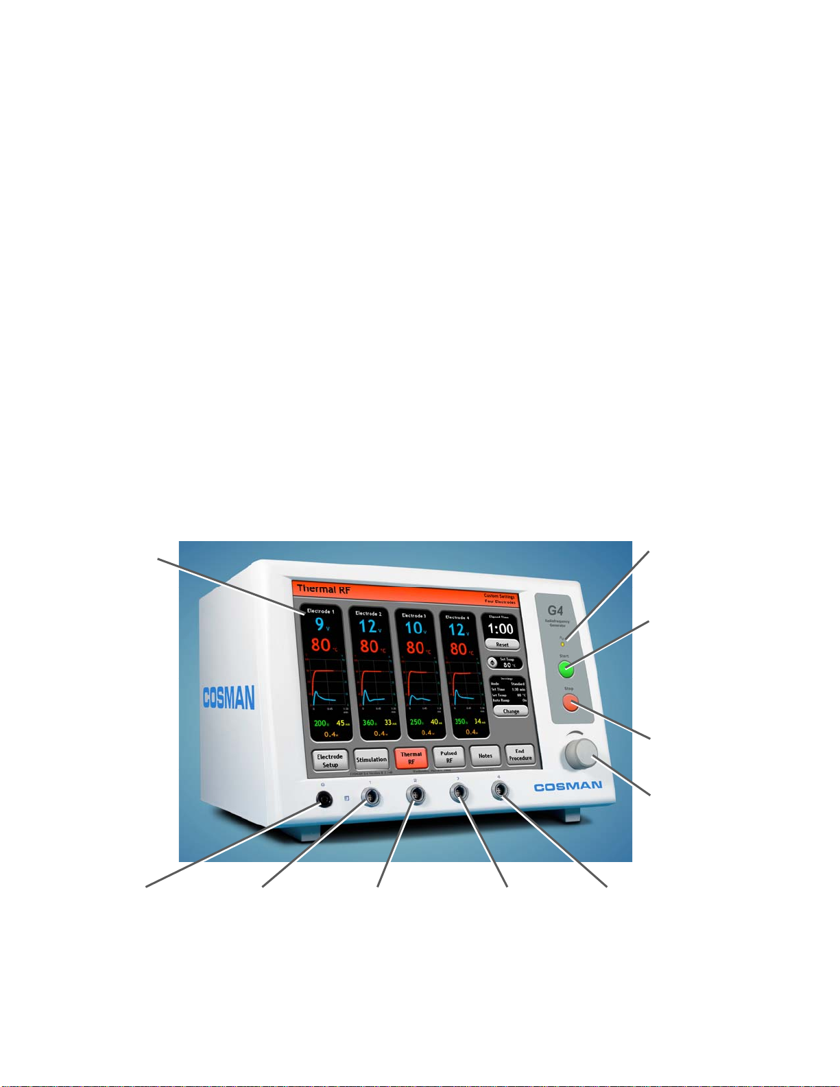
Touch Screen
Output On Indicato
Illuminated when any
electrode out
Front-panel Start Button:
Turn on electrode output
when the Stimulation (Sec.
8.1), Thermal RF (Sec.
8.2), or Pulsed RF (Sec.
8.3) screens are
displayed.
Front-panel Stop Button:
Turn off electrode output
Output Control Knob:
Manual output ramping
when Auto Ramp = Off.
Disabled if Auto Ramp =
On
:
ut is on
Reference Ground
Pad Connection (G)
Electrode Output
Connection 1
Electrode Output
Connection 2
Section 8
Electrode Output
Connection 3
Electrode Output
Connection 4
Page 31
Cosman G4 Radiofrequency Generator Service Manual (SPI 11291 Rev A)
A
r
8.1 Stimulation Screen
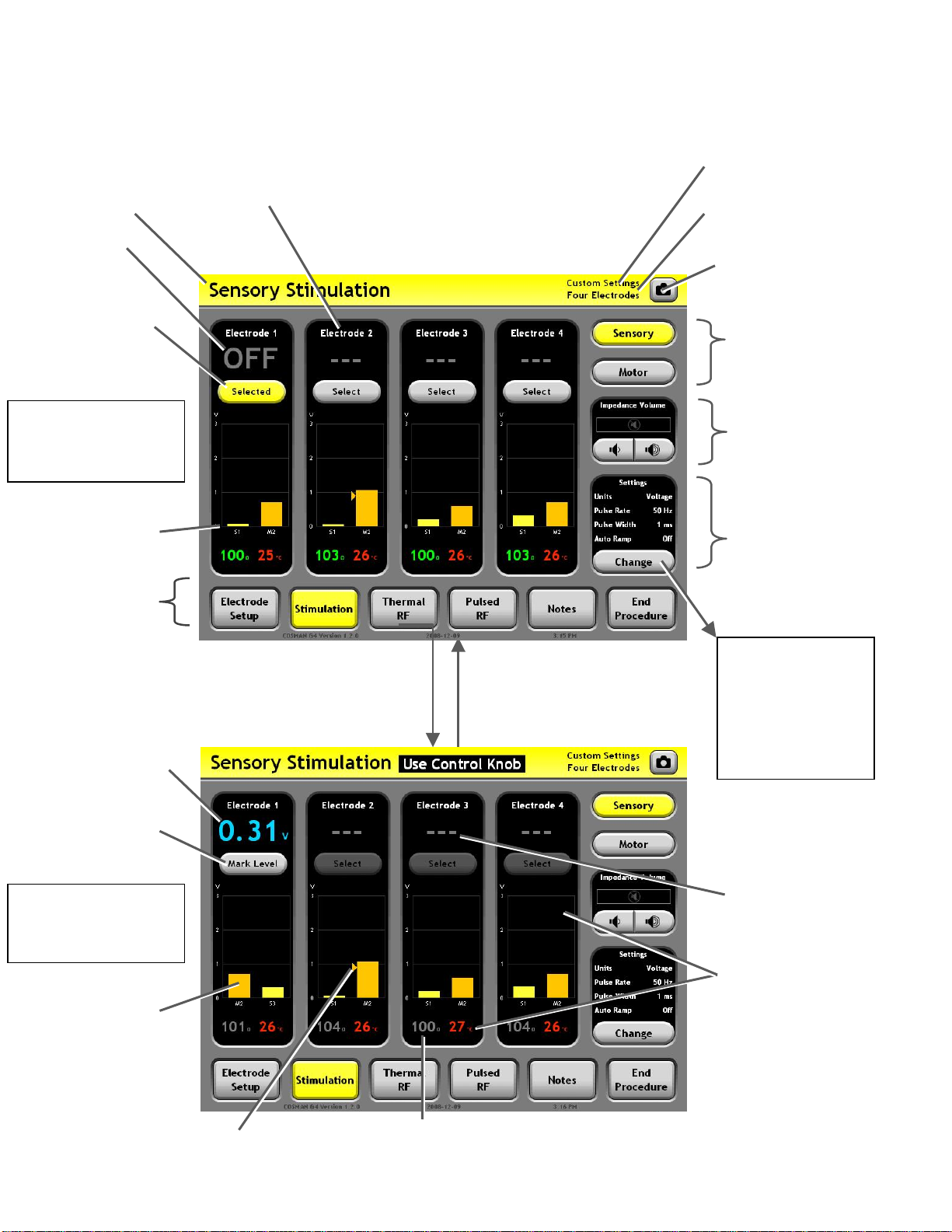
Sensory Mode
Indicator
Output Off
Indicator
Electrode Select
Buttons: The selected
electrode reads
"Selected". Press
"Select" to select other
electrodes.
Sensory
Stimulation Mode
Output Off
Output level bars
held from previous
instances of
Stimulation output
Mode Bar: Access
other procedure
screens
Electrode Panel (Black area):
Displays all readings for the
indicated electrode output.
Personal Settings Preset
Indicato
Electrode Setup Indicator
(Section 7.1)
Screen Shot Button:
Save an image of the
screen to the Procedure
Record.
Mode: Select Sensory
or Motor Stimulation
output settings
Impedance Tone:
Volume of audio tone
with frequency
proportional to
Impedance reading at
selected electrode.
Settings Panel:
Lists the current
Stimulation settings.
Press Change
Button
Output Level Reading:
The level of Stimulation
output being delivered to
the selected electrode in
units of Voltage or
Current, matching the
Stimulation “Control
Units” setting.
Mark Level Button:
nnotate current
output level in
Procedure Record
Sensory
Stimulation Mode
Output On
Output Level Graph:
The height of the
rightmost bar in selected
electrode's panel shows
the level of Stimulation
output being delivered to
the selected electrode.
Bars for past instances
of Sensory and Motor
Stimulation output are
shown on the left for
Press Front-panel Start Button
or depress Footswitch:
Stimulation output is d
only to the selected electrode
or bipolar electrode pair.
Impedance reading: Held at pre-output on value (gray
Marked Level
color) when Stimulation output is on. Reads “--- ”
when Impedance greater than 3000 (open circuit).
elivered
Press Front-panel Stop
Button, release
Footswitch, or error
occurs: Electrode
output is turned off.
Section 8
Stimulation
Settings
Section 8.1.2
• Change settings
for Sensory and
Motor Stimulation
Output
Unselected electrodes
read "---". Stimulation
output is not delivered
to unselected
electrodes.
Temperature reading:
Reads “-- °C” when
Temperature is less
than 10°C or absent.
Page 32
Cosman G4 Radiofrequency Generator Service Manual (SPI 11291 Rev A)
p
8.1.1 Additional Example Screens
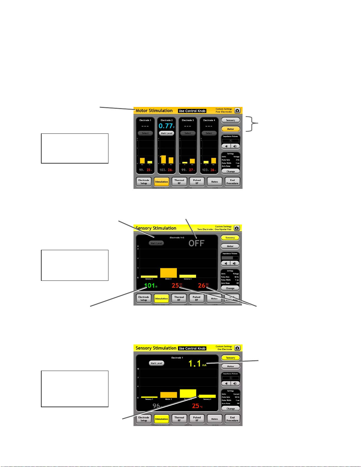
The Graphing Stimulation screen will appear differently depending on the current settings:
• Electrode Setup settings (see Section 7.1)
• Stimulation Mode: Sensory or Motor
• Control Units setting: Voltage- or Current-controlled output (see Section 8.1.2)
Motor Stimulation
Four Electrodes
Motor Mode
Indicator
Mode: Select Sensory
or Motor Stimulation
output
Mode
Electrode Panel (Black area):
Displays all readings for the
indicated bipolar electrode pair,
e.g. “Electrode 1+2”.
Sensory
Stimulation Mode
One Bipolar Pair
Bipolar readings:
Voltage/Current and Impedance
between the two electrodes in
the bi
olar pair
Sensory
Stimulation Mode
One Electrode &
Units= Current
Output Off
Indicator
Temperature Readings:
One Temperature reading
from each electrode in
bipolar pair. For instance,
“E1” indicates a reading
from Electrode 1.
Output Level Reading:
Shown here in units of
Current (mA). This is
determined by the
Control Units = Current.
Marked Level
Section 8
Page 33
Cosman G4 Radiofrequency Generator Service Manual (SPI 11291 Rev A)
A
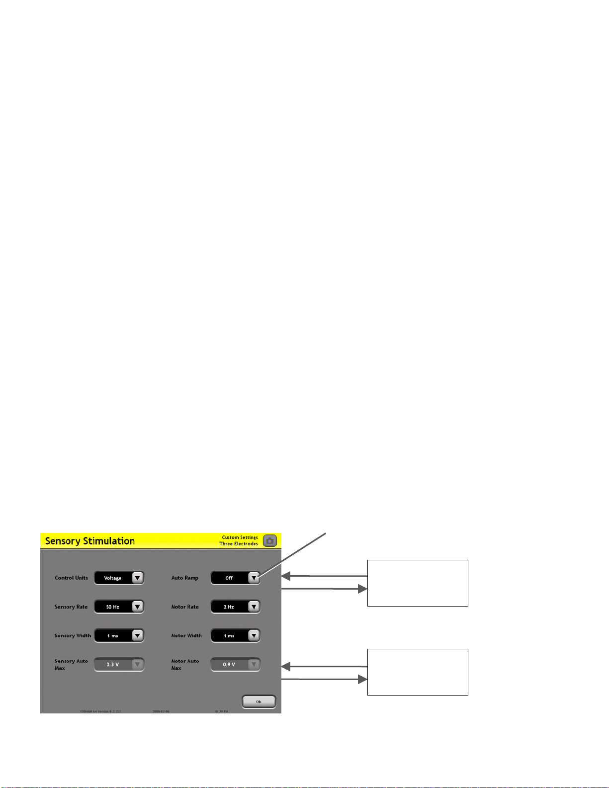
8.1.2 Stimulation Settings
The Electrode Setup settings (Section 7.1) determine the configuration of electrodes when the generator
delivers Sensory and Motor Stimulation output. The "Electrode Select Buttons" on the Stimulation screen
(see Section 8.1) are used to select one electrode at a time, or one bipolar electrode pair at a time, from
those set as "active" on the Electrode Setup screen. Stimulation output is delivered only to the one selected
electrode or bipolar electrode pair. The following settings determine the Stimulation output characteristics.
• Control Units (“Units”):
• Voltage: Sensory and Motor Stimulation output is Voltage-regulated.
• Current: Sensory and Motor Stimulation output is Current-regulated.
• Auto Ramp:
• Off: The Sensory and Motor Stimulation output level is controlled manually by the user with
the Output Control Knob (Graphing Interface Only).
• On: The Sensory and Motor Stimulation output level increases automatically after the user
has turned the output on.
• Sensory Pulse Rate (“Pulse Rate”): The rate of Sensory Stimulation output pulses in units of Hertz
(Hz), which is equivalent to units of “Pulses Per Second”.
• Sensory Pulse Width (“Pulse Width”): The width of Sensory Stimulation output pulses in units of
milliseconds.
• Sensory Auto Ramp Max: The maximum output level if Auto Ramp = On.
• Motor Pulse Rate (“Pulse Rate”): The rate of Motor Stimulation output pulses in units of Hertz
(Hz), which is equivalent to units of “Pulses Per Second”.
• Motor Pulse Width (“Pulse Width”): The width of Motor Stimulation output pulses in units of
milliseconds.
• Motor Auto Ramp Max: The maximum Motor Stimulation output level if Auto Ramp = On.
The Stimulation Settings Screen is shown below.
Select settings from drop-
down menus
Custom Setting
Keypad
Select “Custom”
from a setting
drop-down menu
Stimulation
Screen
Press “Ok”:
ccept selected
settings.
Section 8.1
Section 8
Page 34
8.2 Thermal RF Screen
r
r
p
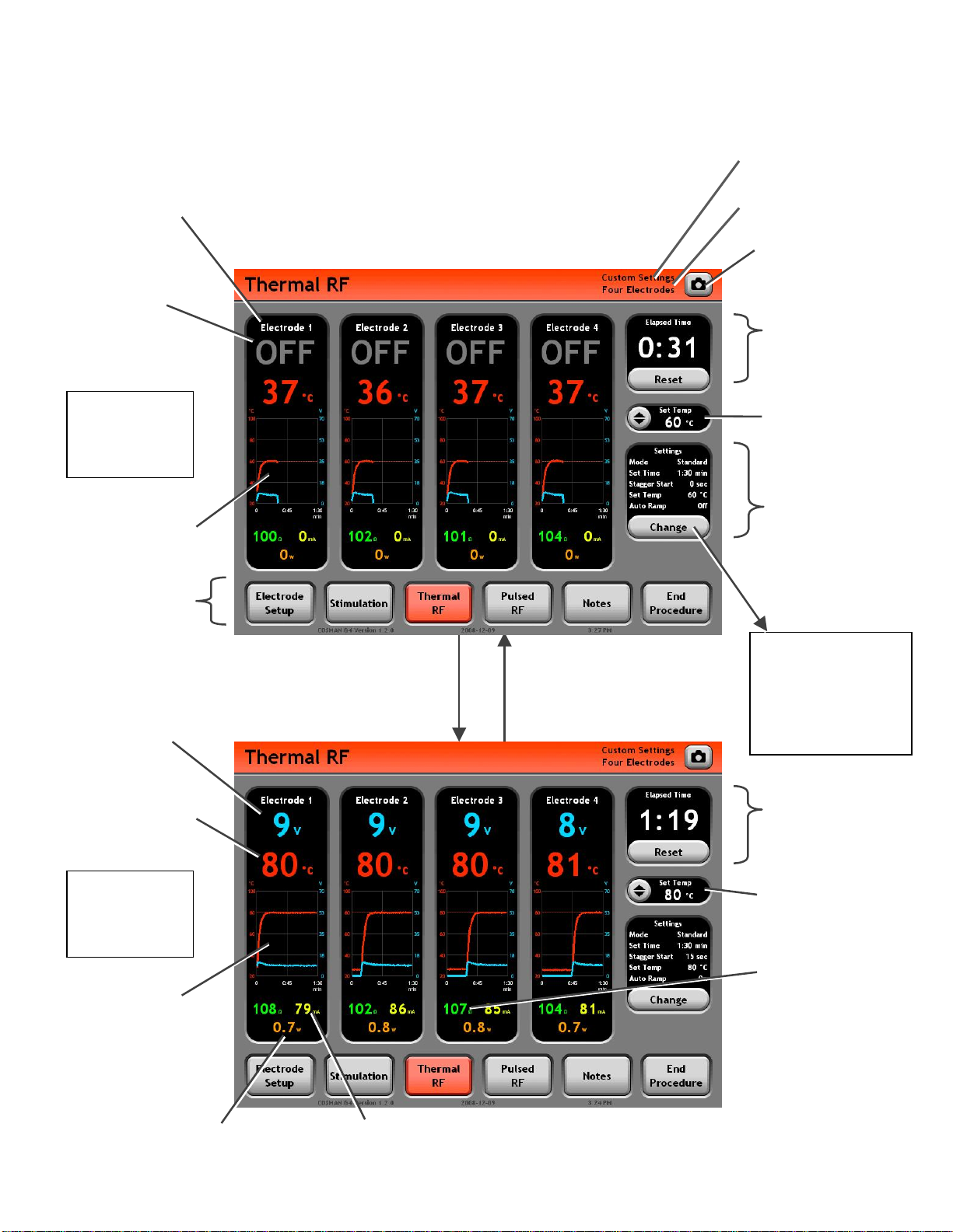
Electrode Panel (Black area):
Displays all readings for the
indicated electrode output. When
enabled, RF output is delivered to
this output.
Output Off
Indicator
Cosman G4 Radiofrequency Generator Service Manual (SPI 11291 Rev A)
Personal Settings Preset
Indicato
Electrode Setup Indicator
(Section 7.1)
Screen Shot Button:
Save an image of the
screen to the Procedure
Record.
Timer: Holds value from
last instance of Thermal
RF output.
Standard
Mode
Output Off
Temperature &
Voltage graphs held
from last instance of
Thermal RF output
Mode Ba
other procedur
screens
RF Voltage Reading:
In units of RMS Volts.
Temperature reading:
Reads “-- °C” when
Temperature is less
than 10°C or absent.
: A
ccess
e
Standard
Mode
Output On
Graphs of
Temperature &
Voltage readings
over time
Press Front-panel Start
Button or depress
Footswitch: Thermal RF
output is delivered to
all active electrodes.
Press Front-panel Stop
Button, release footswitch,
timed output completes, or
error occurs: Electrode
output is turned off.
Set Temp Panel: Cycle
through Set Temp
values when Set Temp
is not “Off”.
Settings Panel: Lists
the current Thermal
RF settings.
Press Change
Button
Thermal RF
Settings
Section 8.2.2
• Change settings
for Thermal RF
output
Timer: Counts up to Set
Temp in Minutes and
Seconds (min:sec) w
RF output is on. Reset
button sets timer to
zero.
Set Temp Panel:
Increment Set Temp by
5 °C (up to 90 °C) if Set
Temp is not “Off”.
Impedance reading:
Held at latest value
(gray color) when
during Stagger Start.
Reads “--- ” when
Impedance greater
than 3000
(open circuit).
hen
RF Power Reading: In
units of RMS Watts.
RF Current Reading: In
units of RMS Milliam
s.
Section 8
Page 35
Cosman G4 Radiofrequency Generator Service Manual (SPI 11291 Rev A)
p
p
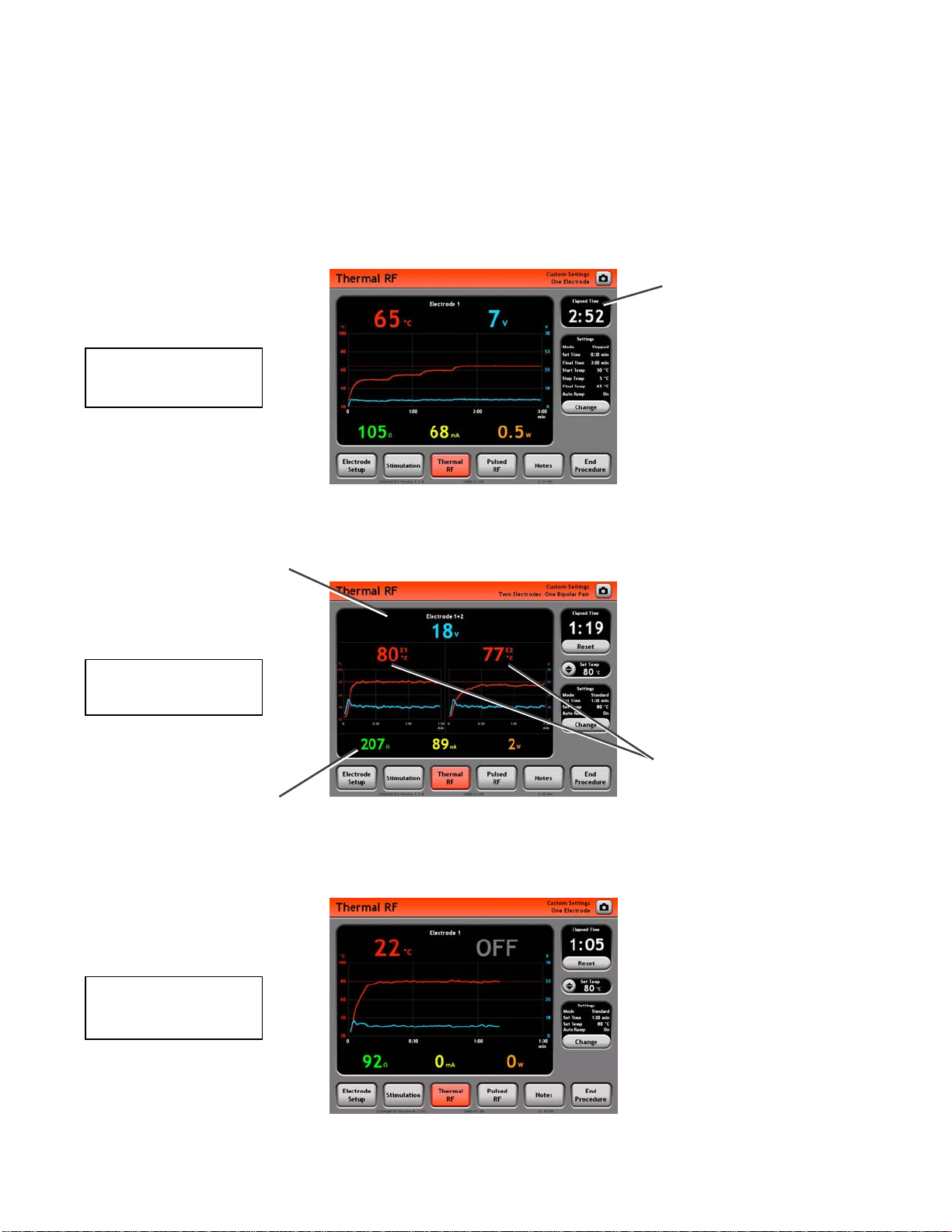
8.2.1 Additional Example Screens
The Graphing Thermal RF screen will appear differently depending on the current settings:
• Electrode Setup settings (see Section 7.1)
• Thermal RF Mode: Standard or Stepped (see Section 8.2.2)
Timer: Cannot be reset
in Stepped Mode.
Stepped Mode
One Electrode
Electrode Panel (Black area):
Displays all readings for the
indicated bipolar electrode pair,
e.g. “Electrode 1+2”.
Standard Mode
One Bi
Bipolar readings: Voltage,
Current, Power, and Impedance
between the two electrodes in
the bi
olar Pair
olar pair
Standard Mode
One Electrode
Temperature Readings:
One Temperature reading
from each electrode in
bipolar pair. For instance,
“E1” indicates a reading
from Electrode 1.
Section 8
Page 36

Cosman G4 Radiofrequency Generator Service Manual (SPI 11291 Rev A)
8.2.2 Thermal RF Settings
The Electrode Setup settings (Section 7.1) determine the number and configuration of electrodes when the
generator delivers Thermal RF output. When Thermal RF output is enabled by the user, it is delivered to all
electrodes selected as “active” on the Electrode Setup screen. The following settings determine the
Thermal RF output characteristics.
• Mode:
• Standard: Time and Temperature control for the Thermal RF output is determined by the Auto
Ramp, Set Temp, and Set Time settings.
• Stepped: Time and Temperature control for Thermal RF output is determined by the Start Temp,
Step Temp Increment, Final Temp, Step Time, and Final Time settings. RF Voltage is controlled
automatically by the generator in order that the Temperatures of active electrodes vary in a
stepwise manner.
• Stagger Start: When using multiple electrodes, electrodes will turn on sequentially from low to high
index, spaced in time by this setting value.
• 0 seconds: All electrodes are energized simultaneous when the user enables Thermal RF
output using the front-panel Start button.
• 5-30 seconds: After the user enables Thermal RF output using the front-panel Start button, each
electrode is not energized until Stagger Start seconds after the previous, lower-indexed
electrode is energized.
The following settings apply only when Thermal RF Mode = Standard.
• Auto Ramp (Graphing Interface Only):
• Off: Thermal RF output Voltage is controlled manually by the user with the Output Control
Knob on the front panel of the generator.
• On: Thermal RF output Voltage increases automatically after the user has turned the output
on. Applicable only when Automatic Temperature Control is enabled (i.e. Set Temp is not
“Off”). The Output Control Knob is inactive.
• Set Temperature (“Set Temp”):
• Off: Automatic Temperature Control is disabled. The generator will not control the Temperature
at any electrode or check for Temperature-related errors. Auto Ramp is set to Off and the
Thermal RF output Voltage must be controlled manually by the user with the Output Control
Knob. Use this setting with electrodes that do not monitor temperature, e.g. Cosman CR
Electrode.
• 37-90 °C: Automatic Temperature Control enabled. Thermal RF output is automatically adjusted
to target the Set Temp value for each electrode.
• Set Time: This setting determines the total amount of time that Thermal RF output is delivered to
each electrode. Once this time interval has elapsed for each electrode, electrode output is disabled
automatically.
Section 8
Page 37
Cosman G4 Radiofrequency Generator Service Manual (SPI 11291 Rev A)
r
)
r
8.3 Pulsed RF Screen
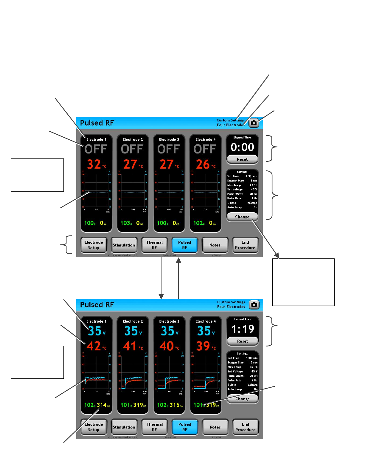
Electrode Panel (Black area):
Displays all readings for the
indicated electrode output. When
enabled, RF output is delivered to
this output.
Output Off
Indicator
E-dose =
Vary Voltage
Output Off
Temperature &
Voltage graphs held
from last instance of
Thermal RF output
(None held here)
Mode Ba
other procedur
screens
: A
ccess
e
Personal Settings Preset
Indicato
Electrode Setup Indicator
(Section 7.1)
Screen Shot Button:
Save an image of the
screen to the Procedure
Record.
Timer: Holds value from
last instance of Thermal
RF output.
Settings Panel: Lists
the current Pulsed RF
settings.
Press Change
Button
RF Voltage Reading:
In units of Peak Volts.
Temperature reading:
Reads “-- °C” when
Temperature is less
than 10°C or absent.
E-dose =
Vary Voltage
Output On
Graphs of
Temperature &
Voltage readings
over time
RF Current Reading:
In units of Peak
Milliamps.
Press Front-panel Start
Button or depress
Footswitch: Pulsed RF
output is delivered to
all active electrodes.
Press Front-panel Stop
Button, release footswitch,
timed output completes, or
error occurs: Electrode
output is turned off.
Section 8
Pulsed RF
Settings
Section 8.3.2
• Change settings
for Thermal RF
output
Timer: Counts up t
Set Temp in Minutes
and Seconds (min:sec)
Impedance reading:
• Held a latest value
(gray color) when
during Stagger S
Reads “
• --- ” when
Impedance greater
than 3000 (open
circuit
.
tart.
Page 38
Cosman G4 Radiofrequency Generator Service Manual (SPI 11291 Rev A)
p
ou
ectrodes
V
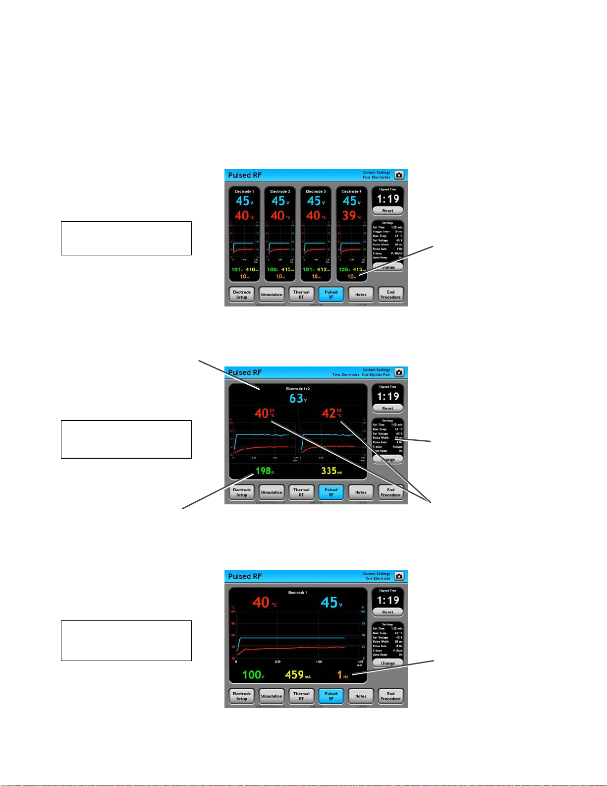
8.3.1 Additional Example Screens
The Graphing Pulsed RF screen will appear differently depending on the current settings:
• Electrode Setup settings (see Section 7.1)
• E-dose setting: Vary Voltage, Vary Width, or Vary Rate (see Section 8.3.2)
Pulse Width Reading:
E-dose = Vary Width
r El
F
Displayed in units of
milliseconds only if E-dose =
Vary Width. The Pulse Ra
is fixed at the value shown
in the Settings Panel.
te
Electrode Panel (Black area):
Displays all readings for the
indicated bipolar electrode pair,
e.g. “Electrode 1+2”.
E-dose = Vary Voltage
One Bipolar Pair
Bipolar readings: Voltage,
Current, and Impedance
between the two electrodes in
the bi
olar pair
E-dose = Vary Rate
One Electrode
Settings Panel: If E-dose =
Vary Width, the Pulse Width
and Pulse Rate are fixed at
the values shown here.
Temperature Readings:
One Temperature reading
from each electrode in
bipolar pair. For instance,
“E1” indicates a reading
from Electrode 1.
Pulse Rate Reading:
Displayed in units of
Hertz only if E-dose =
ary Rate. The Pulse
Width is fixed at the
val
Section 8
Page 39

Cosman G4 Radiofrequency Generator Service Manual (SPI 11291 Rev A)
8.3.2 Pulsed RF Settings
The Electrode Setup settings (Section 7.1) determine the number and configuration of electrodes when the
generator delivers Pulsed RF output. When Pulsed RF output is enabled by the user, it is delivered to all
electrodes selected as “active” on the Electrode Setup screen. The following settings determine the Pulsed
RF output characteristics.
• Stagger Start: When using multiple electrodes, electrodes will turn on sequentially from low to high
index, spaced in time by this setting value.
• 0 seconds: All electrodes are energized simultaneous when the user enables Pulsed RF output
using the front-panel Start button.
• 5-30 seconds: After the user enables Pulsed RF output using the front-panel Start button, each
electrode is not energized until Stagger Start seconds after the previous, lower-indexed
electrode is energized.
• Auto Ramp (Graphing Interface Only):
• Off: Pulsed RF output Voltage is controlled manually by the user with the Output Control
Knob on the front panel of the generator.
• On: Pulsed RF output Voltage increases automatically after the user has turned the output
on. Applicable only when Automatic Temperature Control is enabled (i.e. Max Temp is not
“Off”). The Output Control Knob is inactive.
• E-Dose: Applicable if Automatic Temperature Control is enabled (i.e. Max Temp is not “Off”), one of
the pulse parameters is automatically reduced to keep all electrode temperatures below the Max
Temp setting.
• Vary Voltage: Voltage may be automatically reduced from the Set Voltage setting to keep all
electrode temperatures below the Max Temp setting.
• Vary Pulse Width (“Vary Width”): Pulse Width may be automatically reduced from the
Pulse Width setting to keep all electrode temperatures below the Max Temp setting. Voltage
is reduced when the Pulse Width cannot be reduced below its minimum value.
• Vary Pulse Rate (“Vary Rate”): Pulse Rate may be automatically reduced from the Pulse
Rate setting to keep all electrode temperatures below the Max Temp setting. Voltage is
reduced if the Pulse Rate cannot be reduced below its minimum value.
• Max Temperature (“Max Temp”):
• Off: Automatic Temperature Control is disabled. The generator will not control the Temperature
at any electrode. Auto Ramp is set to Off and the Pulsed RF output Voltage must be controlled
manually by the user with the Output Control Knob.
• 37-90 °C: Automatic Temperature Control enabled. Pulsed RF output is automatically adjusted
so that electrode Temperatures do not exceed the Max Temp value.
• Set Voltage: The target Voltage amplitude of the Pulsed RF output.
• Pulse Width: The duration in milliseconds of each burst of Pulsed RF output.
• Pulse Rate: The rate in Hz (equivalent to “Pulses Per Second”) at which bursts of Pulse RF output
are delivered.
• Set Time: This setting determines the total amount of time that Pulsed RF output is delivered to
each electrode. Once this time interval has elapsed for each electrode, electrode output is disabled
automatically.
Section 8
Page 40
Cosman G4 Radiofrequency Generator Service Manual (SPI 11291 Rev A)
A
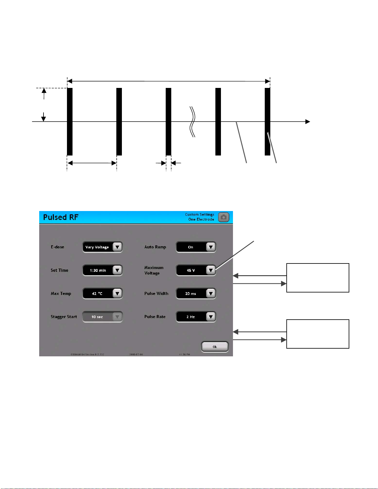
Selected parameters of the Pulsed RF waveform are shown schematically in the illustration below.
Set Time
Voltage
Time
1/Pulse Rate Pulse Width
RF e/ RF off
puls
burst
The Pulsed RF Settings Screen is shown below.
Select settings from
drop-down menus
Select “Custom”
from a setting
drop-down menu
Press “Ok”:
ccept selected
settings.
Custom Setting
Keypad
Pulsed RF
Screen
Section 8.3
Section 8
Page 41
Cosman G4 Radiofrequency Generator Service Manual (SPI 11291 Rev A)
A
r
p
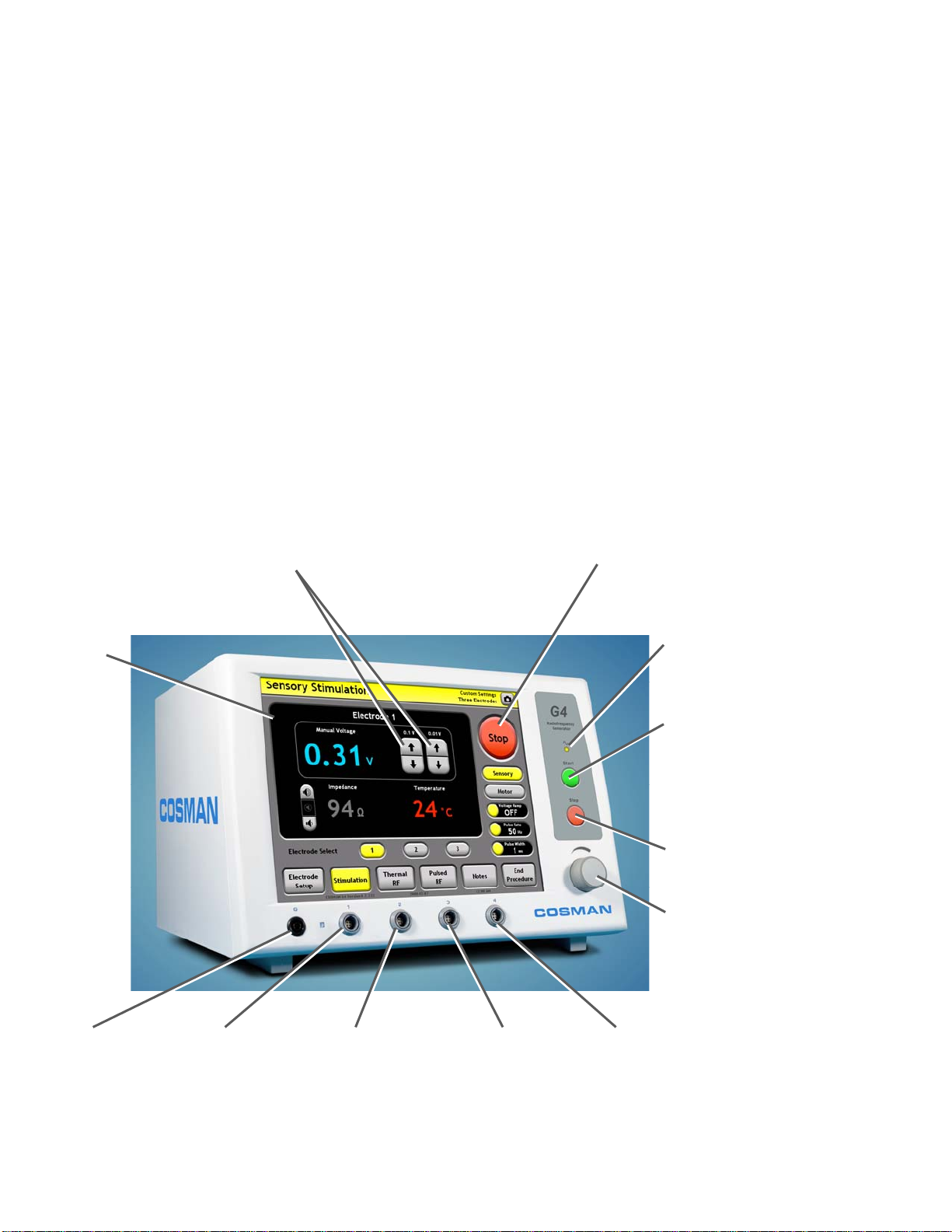
9. One Touch Interface
The One Touch interface is one of two user interfaces available for operation of the generator in
Stimulation, Thermal RF, and Pulsed RF modes. The other is Graphing interface (Section 8). Choice of
user interface is primarily a matter of user preference, since almost all generator functions are available in
both interfaces. The One Touch interface has the following distinguishing characteristics.
• On-screen Start/Stop button: An on-screen Start/Stop toggle button is available to enable and
disable electrode output. The mechanical Start and Stop buttons to the right of the Touch Screen
are still fully functional, but do not need to be used.
• Stimulation Incremental Controls: When the Stimulation “Auto Ramp” setting is Off (see Sections
9.1 & 9.1.2), Stimulation output is incremented and decremented using on-screen buttons, NOT that
Output Control Knob.
• Thermal and Pulsed RF Automatic Control: Automatic output ramping (“Auto Ramp”) cannot be
disabled for Thermal RF and Pulsed RF output unless Automatic Temperature Control is disabled
(see Sections 9.2.2 and 9.2.4). Manual output ramping using the Output Control knob can be
enabled by setting “Auto Ramp” to Off in the Graphing interface (see Section 8).
Stimulation Increment/Decrement Buttons:
vailable on the One Touch Stimulation
screen when Stimulation Auto Ramp = Off.
On-screen Start/Stop Button:
• Press “Start” to turn electrode
output on.
• Press “Stop” to turn electrode
output off.
Touch Screen
Reference Ground
Pad Connection (G)
Electrode Output
Connection 1
Electrode Output
Connection 2
Electrode Output
Connection 3
Electrode Output
Connection 4
Output On Indicato
Illuminated when any
electrode out
Front-panel Start Button:
Turn on electrode output
when the Stimulation (Sec.
9.1), Thermal RF (Sec.
9.2), or Pulsed RF (Sec. 0)
screens are displayed.
Front-panel Stop Button:
Turn off electrode output
Output Control Knob:
Manual output ramping in
TRF & PRF mode if
Set/Max Temp=Off.
Disabled at all other times.
:
ut is on
Section 9
Page 42
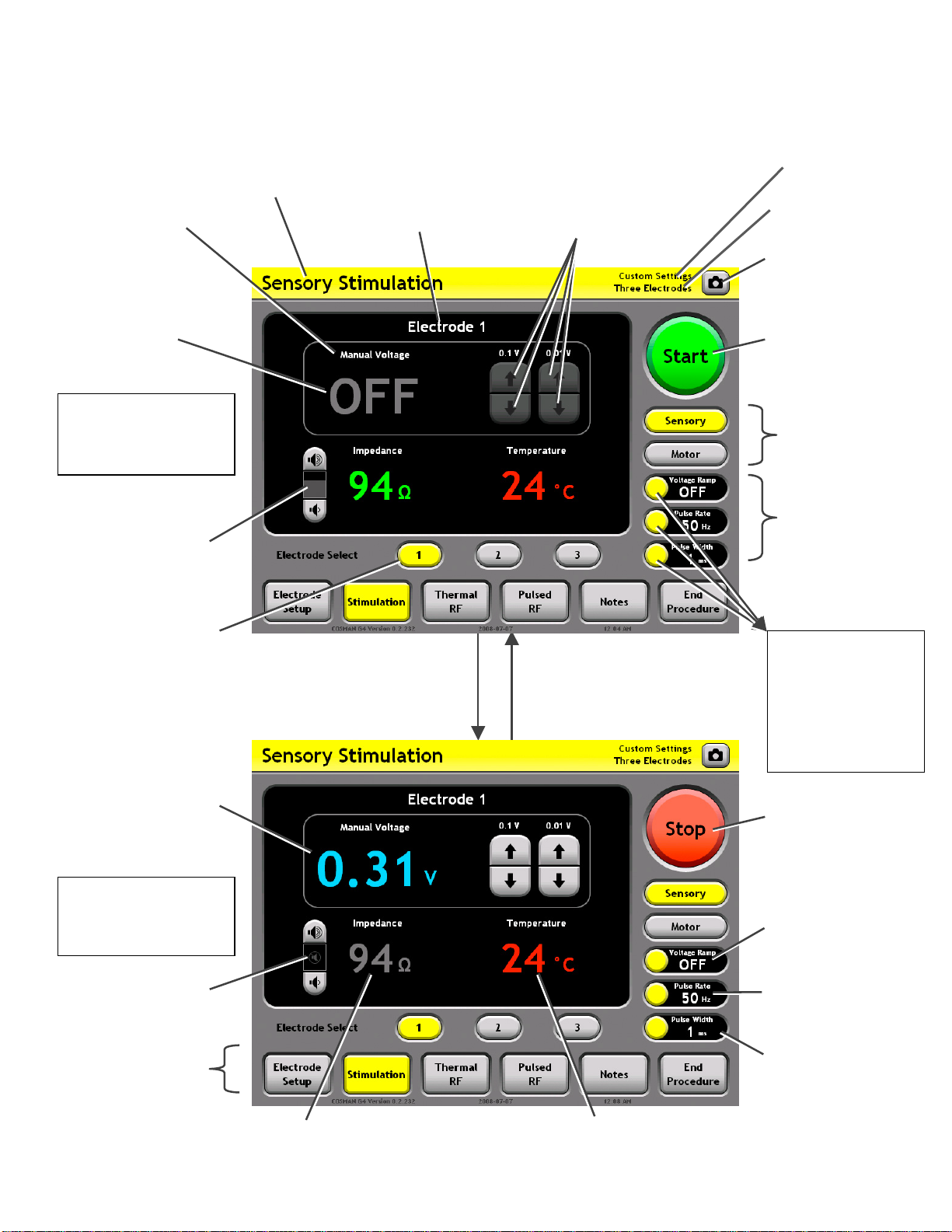
9.1 Stimulation Screen
p
A
r
Auto Ramp & Units
Indicator: Reads
“Auto” if Auto
Ramp=On, and
“Manual” otherwise.
Reads “Voltage” or
“Current” to match the
Control Units setting.
Output Off
Indicator
Sensory
Stimulation Mode
Output Off
Sensory Mode
Indicator
Cosman G4 Radiofrequency Generator Service Manual (SPI 11291 Rev A)
Electrode Panel
(Black area): Displays
all readings for the
indicated, selected
electrode or bipolar
output.
Output Increment & Decrement
Buttons: Increase & decrease
the output level when electrode
output is on and Auto Ramp=Off.
bsent if Auto Ramp = On.
Personal Settings
Preset Indicato
Electrode Setup
Indicator (Section 7.1)
Screen Shot Button:
Save an image of the
screen to the Procedure
Record.
Start/Stop Button:
Press “Start” to turn
electrode output on.
Press “Stop” to turn
electrode output off.
Mode: Select Sensory
or Motor Stimulation
output settings
Impedance Tone:
Volume of audio tone
with frequency
proportional to
Impedance reading at
selected electrode.
Electrode Select
Buttons: The selected
electrode or bipolar
electrode pair is
highlighted.
Output Level Reading:
The level of Stimulation
output being delivered to
the selected electrode in
units of Voltage or
Current, matching the
Stimulation “Control
Units” setting.
Sensory
Stimulation Mode
Output On
Press front-panel or on-screen
Start Button or depress Footswitch:
Stimulation output is delivered t
the selected electrode or bip
electrode pair.
olar
o
creen Press front-panel or on-s
Stop Button, release
Footswitch, or error occurs:
Electrode output is turned
off.
Settings Panels:
Lists the current
Stimulation settings.
Press a Settings
Panel button
Stimulation
Settings
Section 9.1.2
• Change settings
associated with
the target
Settings Panel
Start/Stop Button:
Press “Start” to turn
electrode output on.
Press “Stop” to turn
electrode output off.
Control Units &
Auto Ramp Settings
Impedance Tone:
Muted when electrode
out
ut is on.
Mode Bar: Access
other procedure
screens
Impedance reading: Held at pre-output on value (gray
color) when Stimulation output is on. Reads “--- ”
when Impedance greater than 3000 (open circuit).
Temperature reading: Reads “-- °C” when Temperature is less
than 10°C or absent. Only shown for the selected electrode.
Sensory Pulse Rate
Setting
Sensory Pulse Width
Setting
Section 9
Page 43
Cosman G4 Radiofrequency Generator Service Manual (SPI 11291 Rev A)
A
Units= Current
p
A
A
A
A
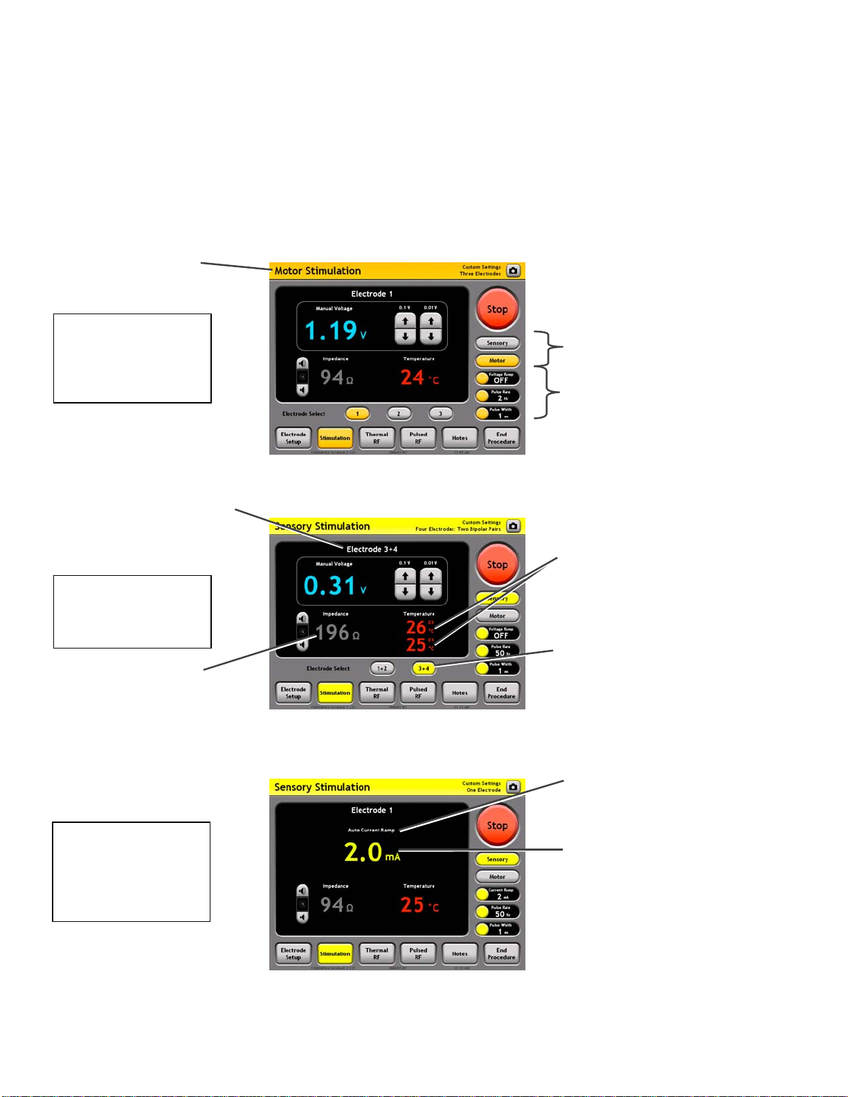
9.1.1 Additional Example Screens
The One Touch Stimulation screen will appear differently depending on the current settings:
• Electrode Setup settings (see Section 7.1)
• Stimulation Mode: Sensory or Motor
• Auto Ramp Setting: Off/Manual or On/Auto (see Section 9.1.2)
• Control Units setting: Voltage- or Current-controlled output (see Section 9.1.2)
Motor Mode
Indicator
Motor Stimulation
Mode
Three Electrodes
Electrode Panel (Black area):
Displays all readings for the
indicated bipolar electrode pair,
e.g. “Electrode 1+2”.
Sensory
Stimulation Mode
Two Bipolar Pairs
Bipolar readings:
Voltage/Current and Impedance
between the two electrodes in
the bi
olar pair
Sensory
Stimulation Mode
One Electrode,
uto Ramp = On &
Mode: Select Sensory
or Motor Stimulation
output
Settings Panels:
Mode switches
between Sensory &
Motor settings
Temperature Readings:
One Temperature reading
from each electrode in
bipolar pair. For instance,
“E1” indicates a reading
from Electrode 1.
Electrode Select Buttons:
Select between bipolar
electrode pairs 1+2 or 3+4.
uto Ramp & Units
Indicator: Reads “Auto” if
uto Ramp=On, and
“Manual” otherwise.
Reads “Voltage” or
“Current” to match the
Control Units setting.
Output Level Reading:
Shown here in units of
Current (mA). This is
determined by the
Control Units = Current.
Electrode Select Buttons:
bsent when Electrode Setup
for one electrode or one
bipolar pair.
Output Increment &
Decrement Buttons:
bsent if Auto Ramp = On.
Section 9
Page 44
Cosman G4 Radiofrequency Generator Service Manual (SPI 11291 Rev A)
A
9.1.2 Stimulation Settings
The Electrode Setup settings (Section 7.1) determine the configuration of electrodes when the generator
delivers Sensory and Motor Stimulation output. The "Electrode Select Buttons" on the Stimulation screen
(see Section 9.1) are used to select one electrode at a time, or one bipolar electrode pair at a time, from
those set as "active" on the Electrode Setup screen. Stimulation output is delivered only to the one selected
electrode or bipolar electrode pair. The following settings determine the Stimulation output characteristics.
• Control Units (“Units”):
• Voltage: Sensory and Motor Stimulation output is Voltage-regulated.
• Current: Sensory and Motor Stimulation output is Current-regulated.
• Auto Ramp:
• Off: The Sensory and Motor Stimulation output level is controlled manually by the on-screen
Output Increment and Decrement buttons (One Touch interface only).
• On: The Sensory and Motor Stimulation output level increases automatically after the user
has turned the output on.
• Sensory Pulse Rate (“Pulse Rate”): The rate of Sensory Stimulation output pulses in units of Hertz
(Hz), which is equivalent to units of “Pulses Per Second”.
• Sensory Pulse Width (“Pulse Width”): The width of Sensory Stimulation output pulses in units of
milliseconds.
• Sensory Auto Ramp Max: The maximum output level if Auto Ramp = On.
• Motor Pulse Rate (“Pulse Rate”): The rate of Motor Stimulation output pulses in units of Hertz
(Hz), which is equivalent to units of “Pulses Per Second”.
• Motor Pulse Width (“Pulse Width”): The width of Motor Stimulation output pulses in units of
milliseconds.
• Motor Auto Ramp Max: The maximum Motor Stimulation output level if Auto Ramp = On.
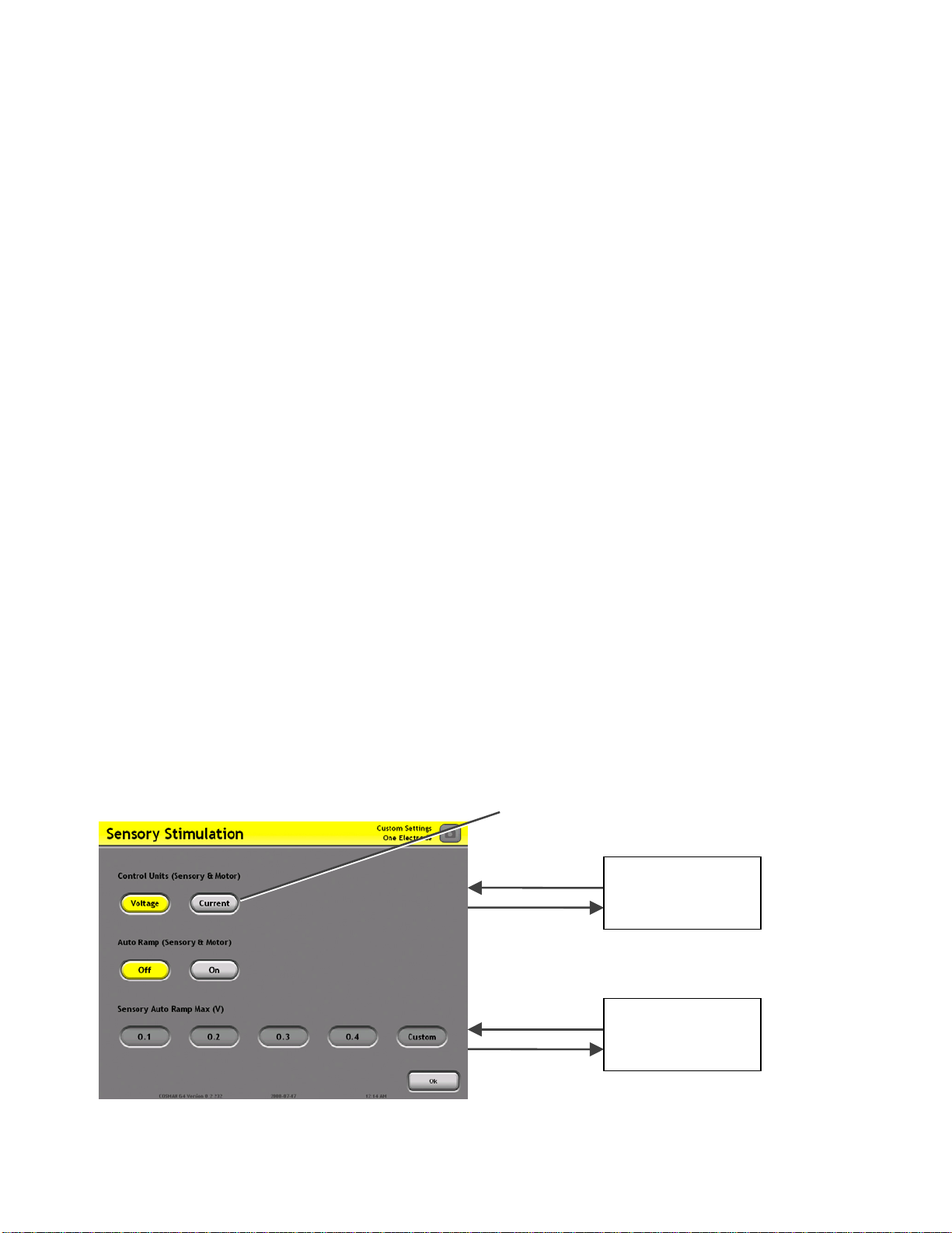
An example of a Stimulation Change Settings screen is shown below.
Select settings from buttons sets
Custom Setting
Keypad
Select “Custom”
from a setting
button set
Stimulation
Screen
Press “Ok”:
ccept selected
settings.
Section 9.1
Section 9
Page 45
Cosman G4 Radiofrequency Generator Service Manual (SPI 11291 Rev A)
r
r
)
g
9.2 Thermal RF Screen
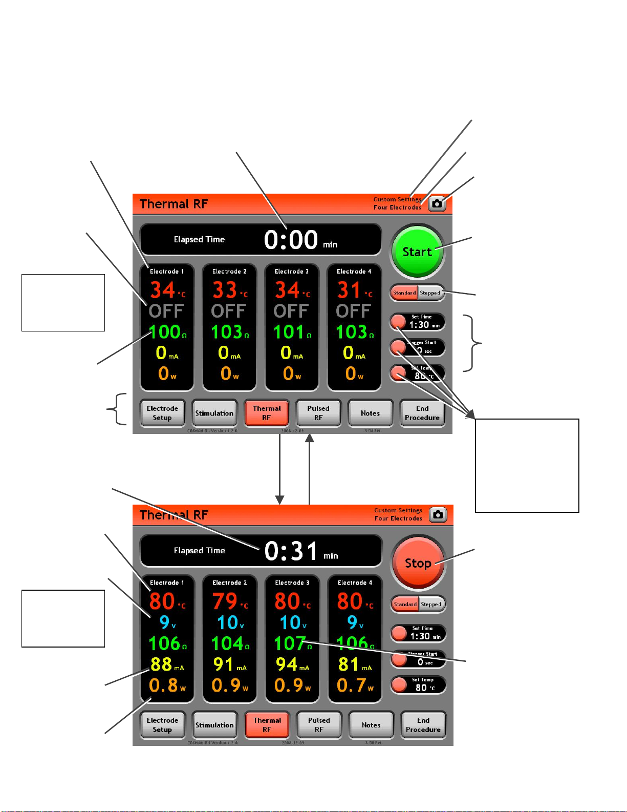
Electrode Panel (Black area):
Displays all readings for the
indicated electrode output. When
enabled, RF output is delivered to
this output.
Output Off
Indicator
Standard
Mode
Output Off
Impedance
Readin
Timer: Holds value from
last instance of Thermal
RF output.
Personal Settings Preset
Indicato
Electrode Setup Indicator
(Section 7.1)
Screen Shot Button:
Save an image of the
screen to the Procedure
Record.
Start/Stop Button:
Press “Start” to turn
electrode output on.
Press “Stop” to turn
electrode output off.
Mode: Select Standard
or Stepped control mode
Settings Panels:
Lists the current
Thermal RF settings.
Mode Ba
other procedur
screens
Timer: Counts up to Set
Temp in Minutes and
Seconds (min:sec) w
RF output is on.
Temperature reading:
Reads “-- °C” when
Temperature is less
than 10°C or absent.
RF Voltage Reading:
In units of RMS Volts.
: A
ccess
e
hen
Standard
Mode
Output On
RF Current Reading:
In units of RMS
Milliamps.
Press front-panel or on-screen
Start Button or depress
Footswitch: Thermal RF output
is delivered to all active
electrodes.
Press front-panel or on-screen
Stop Button, release Footswitch,
timed output completes, or error
occurs: Electrode output is
turned off.
Press a Settings
Panel button
Thermal RF
Settings
Section 9.2.2
• Change settings
associated with
the target
Settings Panel
Start/Stop Button:
Press “Start” to turn
electrode output on.
Press “Stop” to turn
electrode output off.
Impedance reading:
• Held at latest value
(gray color) when
during Stagger S
Reads “
• --- ” when
Impedance greater
than 3000 (open
circuit
.
tart.
RF Power Reading:
In units of RMS
Watts.
Section 9
Page 46
Cosman G4 Radiofrequency Generator Service Manual (SPI 11291 Rev A)
p
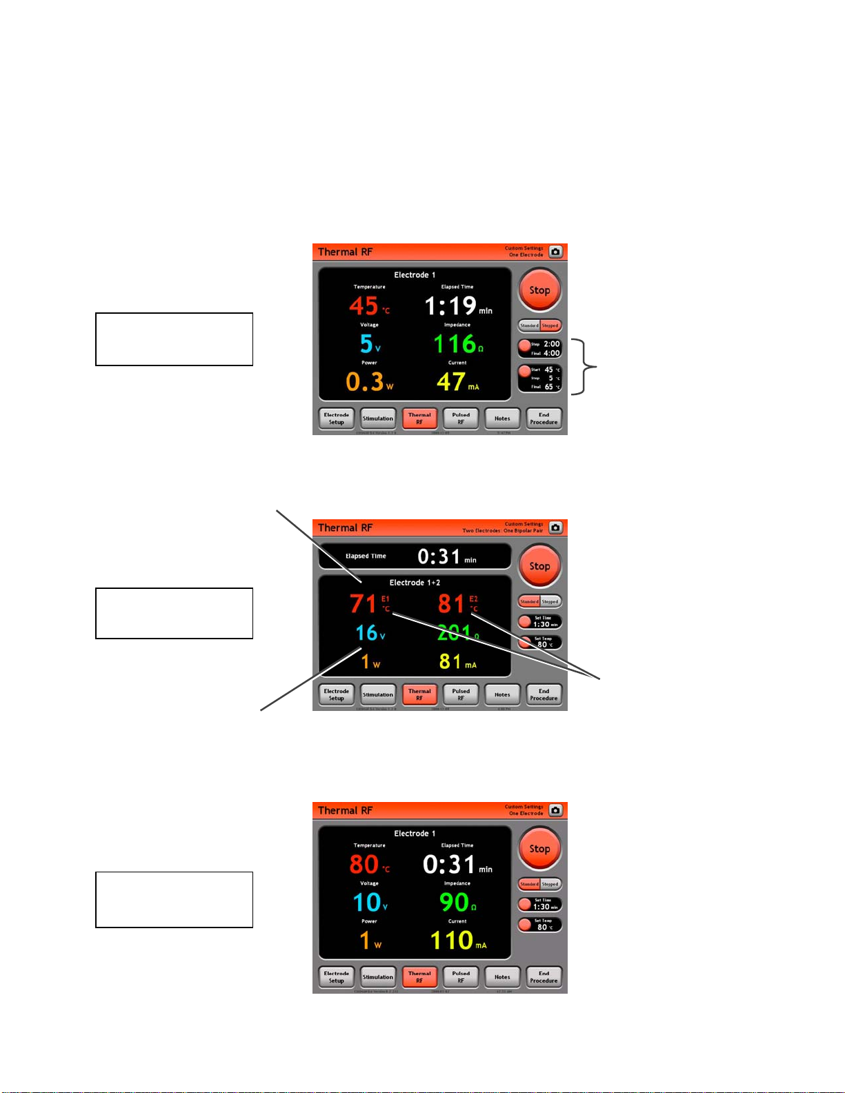
9.2.1 Additional Example Screens
The One Touch Thermal RF screen will appear differently depending on the current settings:
• Electrode Setup settings (see Section 7.1)
• Thermal RF Mode: Standard or Stepped (see Section 9.2.2)
Stepped Mode
Four Electrodes
Settings Panels:
Lists the current
Thermal RF settings
for Stepped mode.
Electrode Panel (Black area):
Displays all readings for the
indicated bipolar electrode pair,
e.g. “Electrode 1+2”.
Standard Mode
One Bipolar Pair
Bipolar readings: Voltage,
Current, Power, and Impedance
between the two electrodes in
the bi
olar pair
Standard Mode
One Electrode
Temperature Readings:
One Temperature reading
from each electrode in
bipolar pair. For instance,
“E1” indicates a reading
from Electrode 1.
Section 9
Page 47

Cosman G4 Radiofrequency Generator Service Manual (SPI 11291 Rev A)
9.2.2 Thermal RF Settings
The Electrode Setup settings (Section 7.1) determine the number and configuration of electrodes when the
generator delivers Thermal RF output. When Thermal RF output is enabled by the user, it is delivered to all
electrodes selected as “active” on the Electrode Setup screen. The following settings determine the
Thermal RF output characteristics.
• Mode:
• Standard: Time and Temperature control for the Thermal RF output is determined by the Auto
Ramp, Set Temp, and Set Time settings.
• Stepped: Time and Temperature control for Thermal RF output is determined by the Start Temp,
Step Temp Increment, Final Temp, Step Time, and Final Time settings. RF Voltage is controlled
automatically by the generator in order that the Temperatures of active electrodes vary in a
stepwise manner.
• Stagger Start: When using multiple electrodes, electrodes will turn on sequentially from low to high
index, spaced in time by this setting value.
• 0 seconds: All electrodes are energized simultaneous when the user enables Thermal RF
output using the front-panel Start button.
• 5-30 seconds: After the user enables Thermal RF output using the front-panel Start button, each
electrode is not energized until Stagger Start seconds after the previous, lower-indexed
electrode is energized.
The following settings apply only when Thermal RF Mode = Standard.
• Auto Ramp: This setting cannot be set by the user in the One Touch interface. It is implicitly set to
On at all times, except when Automatic Temperature Control is disabled (Set Temp = Off), in which
case it is set to Off and the Thermal RF output Voltage must be controlled manually by the user with
the Output Control Knob.
• Set Temperature (“Set Temp”):
• Off: Automatic Temperature Control is disabled. The generator will not control the Temperature
at any electrode or check for Temperature-related errors. Auto Ramp is set to Off and the
Thermal RF output Voltage must be controlled manually by the user with the Output Control
Knob. Use this setting with electrodes that do not monitor temperature, e.g. Cosman CR
Electrode.
• 37-90 °C: Automatic Temperature Control enabled. Thermal RF output is automatically adjusted
to target the Set Temp value for each electrode.
• Set Time: This setting determines the total amount of time that Thermal RF output is delivered to
each electrode. Once this time interval has elapsed for each electrode, electrode output is disabled
automatically.
Section 9
Page 48
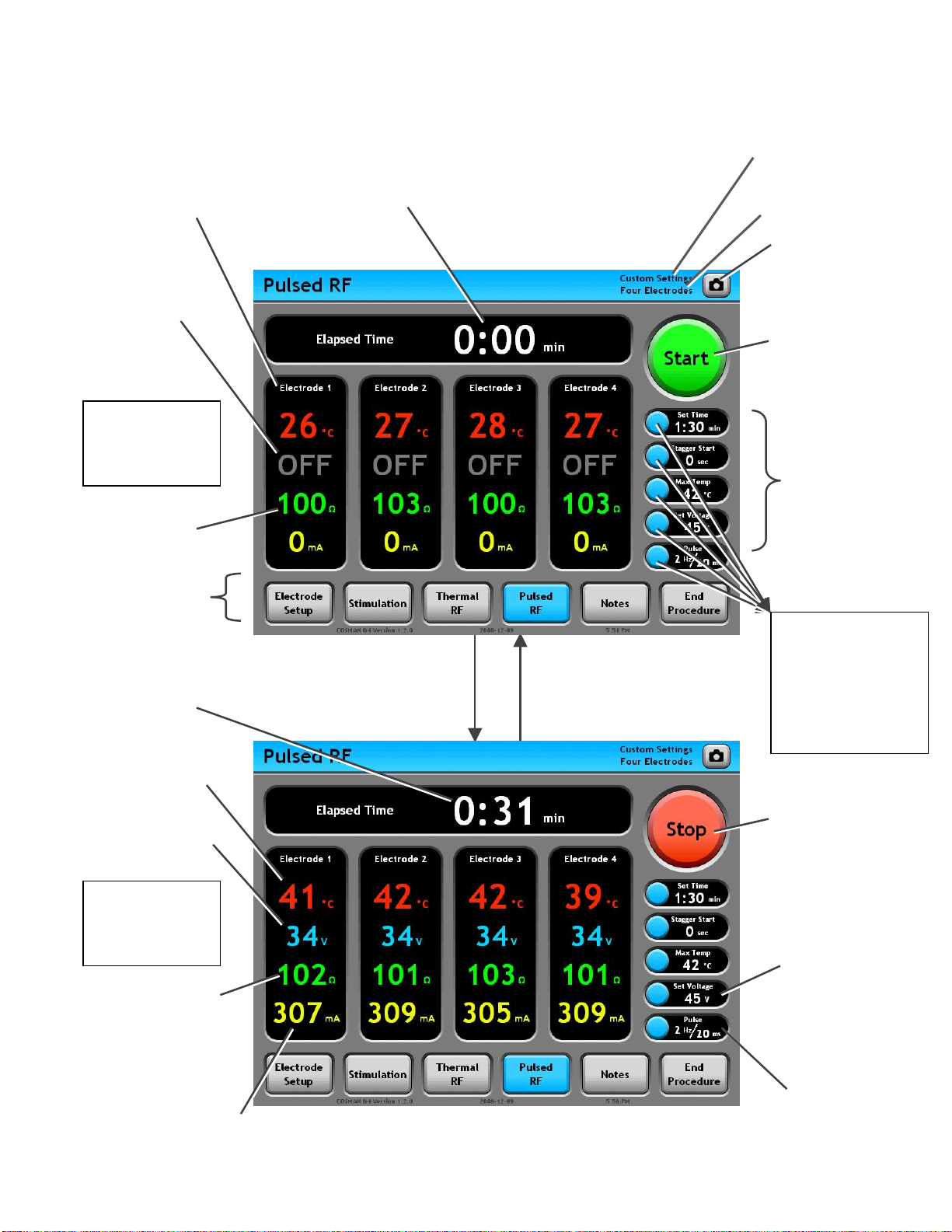
Pulsed RF Screen
r
r
r
)
p
g
Electrode Panel (Black area):
Displays all readings for the
indicated electrode output. When
enabled, RF output is delivered to
this output.
Output Off
Indicator
E-dose =
Vary Voltage
Output Off
Impedance
Readin
Cosman G4 Radiofrequency Generator Service Manual (SPI 11291 Rev A)
Timer: Holds value from
last instance of Pulsed
RF output.
Personal Settings Preset
Indicato
Electrode Setup Indicator
(Section 7.1)
Screen Shot Button:
Save an image of the
screen to the Procedure
Record.
Start/Stop Button:
Press “Start” to turn
electrode output on.
Press “Stop” to turn
electrode output off.
Settings Panels:
Lists the current
Pulsed RF settings.
Mode Ba
other procedur
screens
Time
Temp in Minutes and
Seconds (min:sec) w
RF output is on.
Temperature reading:
Reads “-- °C” when
Temperature is less
than 10°C or absent.
RF Voltage Reading:
In units of Peak Volts.
: A
ccess
e
: Counts up to Set
hen
E-dose =
Vary Voltage
Output On
Impedance reading:
• Held a latest value
(gray color) when
during Stagger S
Reads “
• --- ” when
Impedance greater
than 3000 (open
circuit
.
tart.
RF Current Reading: In units
of Peak Milliam
Press front-panel or on-screen
Start Button or depress
Footswitch: Pulsed RF output
is delivered to all active
electrodes.
s.
Press front-panel or on-screen
Stop Button, release Footswitch,
timed output completes, or error
occurs: Electrode output is
turned off.
Press a Settings
Panel button
Pulsed RF
Settings
Section 9.2.4
• Change settings
associated with
the target
Settings Panel
Start/Stop Button:
Press “Start” to turn
electrode output on.
Press “Stop” to turn
electrode output off.
Set Voltage &
E-dose Settings
Pulse Rate,
Pulse Width &
E-dose Settings
Section 9
Page 49
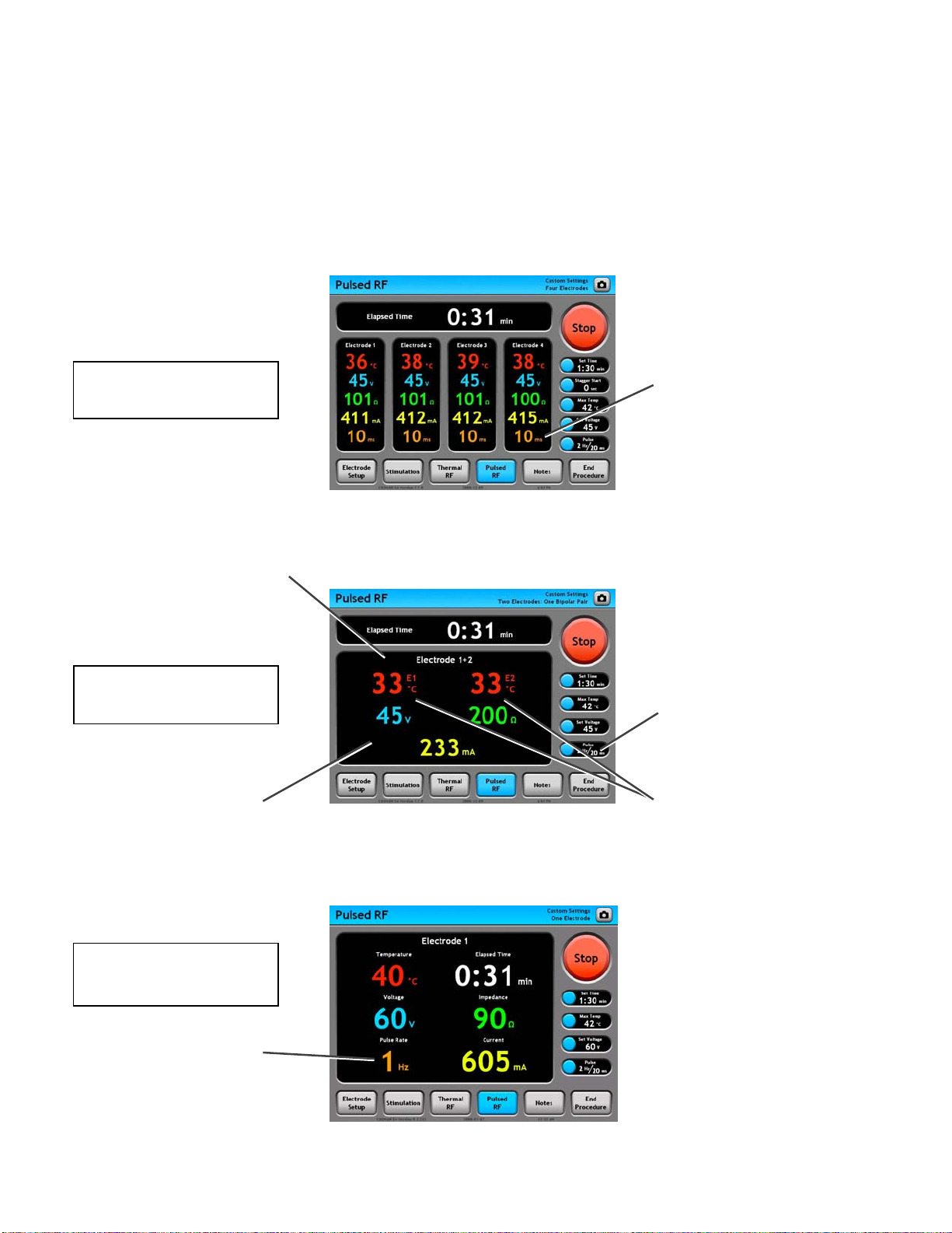
Cosman G4 Radiofrequency Generator Service Manual (SPI 11291 Rev A)
p
9.2.3 Additional Example Screens
The One Touch Pulsed RF screen will appear differently depending on the current settings:
• Electrode Setup settings (see Section 7.1)
• E-dose setting: Vary Voltage, Vary Width, or Vary Rate (see Section 9.2.4)
Pulse Width Reading:
E-dose = Vary Width
Four Electrodes
Displayed in units of
milliseconds only if E-dose =
Vary Width. The Pulse Ra
is fixed at the value shown
in the Settings Panel.
te
Electrode Panel (Black area):
Displays all readings for the
indicated bipolar electrode pair,
e.g. “Electrode 1+2”.
E-dose = Vary Voltage
One Bipolar Pair
Bipolar readings: Voltage,
Current, and Impedance
between the two electrodes in
the bi
olar pair
E-dose = Vary Rate
One Electrode
Pulse Panel: If E-dose =
Vary Width, the Pulse Width
and Pulse Rate are fixed at
the values shown here.
Temperature Readings:
One Temperature reading
from each electrode in
bipolar pair. For instance,
“E1” indicates a reading
from Electrode 1.
Pulse Rate Reading:
Displayed in units of Hertz
only if E-dose = Vary Rate.
The Pulse Width is fixed at
the value shown in the
Settings Panel.
Section 9
Page 50

Cosman G4 Radiofrequency Generator Service Manual (SPI 11291 Rev A)
9.2.4 Pulsed RF Settings
The Electrode Setup settings (Section 7.1) determine the number and configuration of electrodes when the
generator delivers Pulsed RF output. When Pulsed RF output is enabled by the user, it is delivered to all
electrodes selected as “active” on the Electrode Setup screen. The following settings determine the Pulsed
RF output characteristics.
• Stagger Start: When using multiple electrodes, electrodes will turn on sequentially from low to high
index, spaced in time by this setting value.
• 0 seconds: All electrodes are energized simultaneous when the user enables Pulsed RF output
using the front-panel Start button.
• 5-30 seconds: After the user enables Pulsed RF output using the front-panel Start button, each
electrode is not energized until Stagger Start seconds after the previous, lower-indexed
electrode is energized.
• Auto Ramp: This setting cannot be set by the user in the One Touch interface. It is implicitly set to
On at all times, except when Automatic Temperature Control is disabled (Max Temp = Off), in which
case it is set to Off and the Pulsed RF output Voltage must be controlled manually by the user with
the Output Control Knob.
• E-Dose: Applicable if Automatic Temperature Control is enabled (i.e. Max Temp is not “Off”), one of
the pulse parameters is automatically reduced to keep all electrode temperatures below the Max
Temp setting.
• Vary Voltage: Voltage may be automatically reduced from the Set Voltage setting to keep all
electrode temperatures below the Max Temp setting.
• Vary Pulse Width (“Vary Width”): Pulse Width may be automatically reduced from the
Pulse Width setting to keep all electrode temperatures below the Max Temp setting. Voltage
is reduced when the Pulse Width cannot be reduced below its minimum value.
• Vary Pulse Rate (“Vary Rate”): Pulse Rate may be automatically reduced from the Pulse
Rate setting to keep all electrode temperatures below the Max Temp setting. Voltage is
reduced if the Pulse Rate cannot be reduced below its minimum value.
• Max Temperature (“Max Temp”):
• Off: Automatic Temperature Control is disabled. The generator will not control the Temperature
at any electrode. Auto Ramp is set to Off and the Pulsed RF output Voltage must be controlled
manually by the user with the Output Control Knob.
• 37-90 °C: Automatic Temperature Control enabled. Pulsed RF output is automatically adjusted
so that electrode Temperatures do not exceed the Max Temp value.
• Set Voltage: The target Voltage amplitude of the Pulsed RF output.
• Pulse Width: The duration in milliseconds of each burst of Pulsed RF output.
• Pulse Rate: The rate in Hz (equivalent to “Pulses Per Second”) at which bursts of Pulse RF output
are delivered.
• Set Time: This setting determines the total amount of time that Pulsed RF output is delivered to
each electrode. Once this time interval has elapsed for each electrode, electrode output is disabled
automatically.
Section 9
Page 51
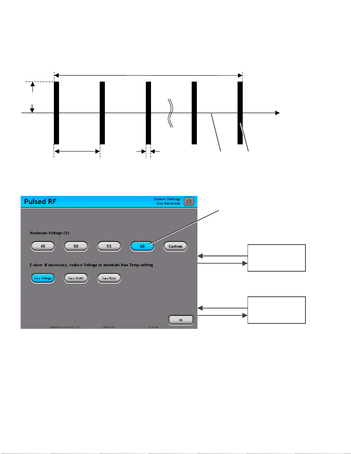
Cosman G4 Radiofrequency Generator Service Manual (SPI 11291 Rev A)
A
g
Selected parameters of the Pulsed RF waveform are shown schematically in the illustration below.
Set Time
Voltage
Time
1/Pulse Rate Pulse Width
RF e/ RF off
puls
burst
An Example of a Pulsed RF Change Settings screen is shown below.
Select settin
s from buttons sets
Select “Custom”
from a setting
button set
Custom Setting
Keypad
Pulsed RF
Screen
Press “Ok”:
ccept selected
settings.
Section 8.3
Section 9
Page 52
Cosman G4 Radiofrequency Generator Service Manual (SPI 11291 Rev A)
10. Sterilization, Care, and Service
10.1.1 Sterilization
CAUTION: It is recommended the CB112-TC, the SKG Knob and the RFG-
STP Test Pad be sterilized by steam autoclave.
The above parts may be sterilized in a Prevacuum Sterilizer at 132-135 °C
(270-275 °F) for at least 4 minutes.
No other parts may be autoclaved.
10.1.2 Care
The G4 may be cleaned by wiping with a soft cloth dampened with a mild detergent. Do not allow liquid to
get into the unit.
The cables and accessories may be wiped with mild detergent cleaning solutions, taking care to keep
moisture out of the connectors. Store in a clean, dry and non-corrosive atmosphere. The generator is
designed to withstand all normally encountered environmental conditions. Do not drop or bang the
generator.
10.1.3 Service
WARNING: Electric Shock Hazard
There are no user serviceable parts inside the G4. To avoid electric shock, return the
device to Cosman for servicing.
To ensure accuracy of unit output and displays, the unit should be tested yearly.
In case of failure or malfunction of the device, discontinue use and report the failure or malfunction to
Cosman Medical. For any electrical malfunction, accident, misuse, alteration, or other damage, return the
unit immediately to Cosman Medical with a problem description.
Contact Cosman Medical Customer Service for further assistance if needed.
Fuse Replacement
WARNING: Risk of fire. Fuse must be replaced as marked.
The generator has two fuses, one for line and one for neutral conductors. Replace with T2AL250V (“T”
indicates slow blow or time lag fuse.)
Section 10
Page 53

Cosman G4 Radiofrequency Generator Service Manual (SPI 11291 Rev A)
This page intentionally blank
Section 10
Page 54

Cosman G4 Radiofrequency Generator Service Manual (SPI 11291 Rev A)
11. Troubleshooting
Problem Possible Cause
Generator will not turn on by Mains Power
switch
No response when button is pressed
No response when Touch Screen is
pressed
Short Circuit Error
• Bad AC outlet
• Defective power cord
• Blown fuses
• Button has no function in current
operating mode, e.g. Start button only
functional on Stimulation, Thermal RF,
and Pulsed RF screens
• Button stuck in depressed possible (Error
message & alarm will sound)
• Button is broken
• Touch Screen is not calibrated (See
Section 5 & 5.2)
• Region of screen contains a “disabled”
(grayed-out) button or no button
• Touch screen is broken
• System software error
• Electrode in contact with reference
structure, such as ground pad
• Bipolar electrodes in contact with each
other
• No electrode output
• No Impedance Reading (“--- ”)
• Open Circuit Error
• No Temperature Reading (“-- °C”)
• No Temperature Error
Voltage or Current does not increase
automatically when electrode output is
turned on
Stimulation, Thermal RF, or Pulsed RF
output will not turn on
• No ground connection
• Problem with electrode
• Break on electrode cable
• Problem with electrode
• Break on electrode cable
• Auto Ramp setting is “Off” (see Sections
8.1.2, 8.2.2 & 8.3.2 for Graphing
interface; 9.1.2, 9.2.2 & 9.2.4 for One
Touch interface)
• Output Control Knob not in minimum
position
• Open or Short Circuit Impedance reading
• No Temperature on electrode or
• Temperature below 10 °C
• Temperature above 100 °C, Set Temp, or
Max Temp setting.
• Electrodes attached to generator do not
match Electrode Setup
Stimulation, Thermal RF, or Pulsed RF
• Open or Short Circuit Impedance reading
Section 11
Page 55

Cosman G4 Radiofrequency Generator Service Manual (SPI 11291 Rev A)
Problem Possible Cause
output shuts down prematurely
Temperature does not reach Set Temp or
Max Temp setting
• Temperature above 100 °C.
• Break in electrode or electrode cables.
May be intermittent problem.
• Set Time setting too low
• Maximum RF Current or Power limit
exceeded
• Electrodes attached to generator do not
match Electrode Setup
• Required total RF Current or Power limit
exceeds allowed limit
• Total Impedance too low
• Too many electrodes energized
simultaneously
• Set Temp or Max Temp too high
• Temperature can only be controlled on
one electrode in a Bipolar Pair
• Ground pad used when RF Type=Bipolar
Section 11
Page 56

Cosman G4 Radiofrequency Generator Service Manual (SPI 11291 Rev A)
12. Specifications
ELECTRICAL SUPPLY
Voltage Specifications: Volts
100Vac 90-110
120Vac 105-125
220Vac 200-240
240Vac 220-260
Maximum input voltage: 260Vac
Maximum voltage on
any input connector: 260Vac
Maximum input power: 480VA
Supply current: 2.0 Amp ~ alternating current sinusoidal wave
Fusing: 2.0 Amp (T) time-lag
Frequency: 50/60 Hz
ENVIRONMENT OPERATING RANGE
Temperature: 15 – 40 °C
Humidity: 15 – 80% non-condensing relative humidity
Atmospheric Pressure: 500 – 1060 hPa
TRANSPORT AND STORAGE ENVIRONMENT
Temperature: 0 – 50 °C
Humidity: 15 – 80% non-condensing relative humidity
Atmospheric Pressure: 500 – 1060 hPa
IMPEDANCE MONITOR
Range: 0 – 3000 ohms digital
Resolution: 1 ohm between 0 – 999, 100 ohms between 1000 – 3000
Accuracy: ± 20 ohms between 30 and 100 ohms
± 20% between 51 and 3000 ohms
STIMULATOR OUTPUT
Rate: 2, 5, 50, 75, 100, 150, 180, 200Hz
Duration: 0.1, 0.5, 1, 2, 3 milliseconds
Voltage Stimulation Mode: 0 – 3 volts
Constant Current Stim. Mode: 0 –10 mA
THERMAL & PULSED RF OUTPUT
Timing: Selectable: 0:30 – 30:00 minutes
Resolution: 1 second
Accuracy: ± 1%
Watts: 0 to 50 watts RMS (into 100 load)
Resolution: 1 watt (in Thermal RF output only)
Accuracy: ± 20% of full scale (in Thermal RF output only)
Frequency: 480 kHz
(mains switch unit) Volts input range
Section 12
Page 57

Cosman G4 Radiofrequency Generator Service Manual (SPI 11291 Rev A)
THERMAL & PULSED RF OUTPUT (continued)
Volts: 0 to 70 volts RMS into 100 load during Thermal RF output.
0 to 100 volts peak into 100 during Pulsed RF output.
Resolution: 1 volt RMS during Thermal RF output
1 volt peak during Pulsed RF output
Accuracy: ± 10% of full scale
Current: 0 to 700 mA RMS
Resolution: 1 mA RMS during Thermal RF output
1 mA peak during Pulsed RF output
Accuracy: ± 10% of full scale
PULSED RF SETTINGS:
Repetition Rate: 1, 2, 3, 4, 5, 6, 7, 8 PPS (Hz)
Burst Duration: 0.5, 1, 5, 10, 20, 30 ms
TEMPERATURE MONITOR
Range: 0 – 110°C
Resolution: 1 °C
Accuracy: ± 3 °C between 40 and 90 °C
± 4 °C between 10 and 40 °C, and between 90 and 110 °C
GENERAL
Size: W 14.25” (36.2 cm), H 9.5” (24.1 cm), D 12.15” (30.9 cm)
Weight: 22 lbs (10 kg)
Section 0
Page 58
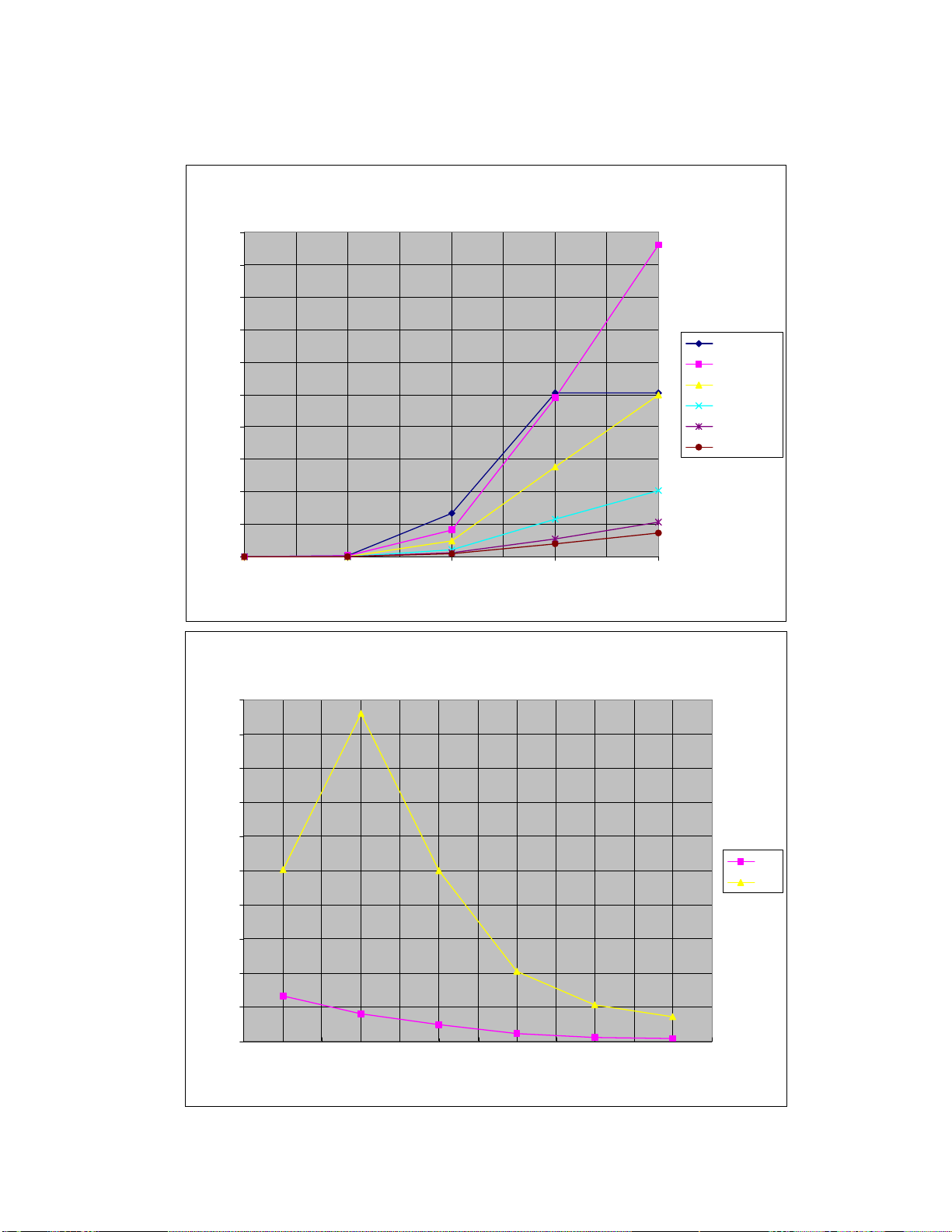
Cosman G4 Radiofrequency Generator Service Manual (SPI 11291 Rev A)
13. Output Power Curves
50
45
40
Output Power ver Knob Setting
35
30
25
Watts
20
15
10
5
0
0255075100
Knob Setting
Output Power ver Resistance
50
45
40
50 ohms
100 ohms
200 ohms
500 ohms
1000 ohms
1500 ohms
35
30
25
Watts
20
15
10
5
0
Half
Full
50 100 200 500 1000 1500
Re si sta nc e
Section 13
Page 59

Cosman G4 Radiofrequency Generator Service Manual (SPI 11291 Rev A)
14. Accessories
Cosman Medical Part No. Description
CB112-TC Connecting Cable for TC Electrodes
C119 Power Cord (120 Volts)
C118 Power Cord (foreign style, 230 Volts)
FUSE-2A 2.0 Amp Fuse (2)
RFG-TP Output Test Plug
RFG-STP Sterilizable Electrode Test Pad
FS-1 Footswitch
SKG Sterilizable Knob (Gold)
CB103B Reference Cable, 3m, w/Alligator Clip
CB103R Active cable, 8ft., Red, w/Alligator Clip, for non-TC electrodes
DGP-PM Electrosurgical Grounding Pad (disposable)
Section 14
Page 60

Cosman G4 Radiofrequency Generator Service Manual (SPI 11291 Rev A)
15. Test Equipment
• AC Power source • Footswitch
• AC/DC voltmeter • Fully populated USB Card PC board
• 2 Channel Oscilloscope • Scope Probes
• 40/90 Temp Baths • Ground Bond Tester
• Omega Temp meter and Probe • Kelvin test cables
• 4ea Test Plugs • Hipot tester
• Universal safety tester (leakage current
tester)
• Resistance Substituter (as needed)
• Power cord • CB112 Cable
• Test leads, Patient Lead • CB103R Cable
• Test Mono-polar Electrode • Test Reference Adaptor Cable
Note: If any of the tests fail, use the schematics and part specs to determine the faulty component or
assembly fill out a Reject tag (SPI#10015-3) attach to the component or assembly under test (PCB,
Transformer, unit assembly, etc) and place in the MRB Area for disposition. On the original Data Sheet
explain the nature of the failure. Obtain a new blank data sheet and restart the testing. The new data sheet
must be attached to the original.
• 110v-220v adapter plug
• Ground Bond tester
• 4ea 100Ω, 500Ω, and 1KΩ high power
non-inductive resistors
16. System Testing
16.1 Application Program check
Turn the power on and watch the screen for errors that would indicate one or more of the files was not
loaded correctly.
The screen will change to the Main Menu screen.
The Application rev will be displayed on the bottom of the screen.
Record this value for reference purposes on the data sheet
If any errors appear the unit must be returned to Cosman Medical for evaluation and repair.
16.2 Low voltage Oscillator resonance check
Attach a 25 (4x100 ) load between the connectors using test cables.
Using an oscilloscope measure the signal across the output and reference jacks.
With the 25 load the signal should be larger than .5v peak to peak.
Open circuit the signal should be smaller than 2.5v peak to peak.
With a single 100 load the signal should be smaller than 2v peak to peak.
If the values differ substantially from those listed above the unit must be returned to Cosman Medical for
evaluation and repair.
16.3 Touch Screen Display test
A couple of seconds after the unit is turned on the LCD screen will display a Start-Up image.
The first time the system is started or any time the date has not been set (removing the battery) the
system should automatically go to the System Settings display.
Record Pass Fail on the traveler for initial display
If the system date has already been set then you must select the System settings button on the LCD
screen
The display should change to the system settings menu
Section 15
Page 61

Cosman G4 Radiofrequency Generator Service Manual (SPI 11291 Rev A)
Using a stylist (pointer) set the screen calibration (be sure to select as close to the center of the crosshair as possible
Set the time date and day using the up down on screen buttons
Adjust the Output Volume setting by selecting each of the available settings.
Adjust P5 on the Backplane PC board (11070) so that the speaker is not over driven when the Output
volume is set to high and is just audible when set to Low.
Set the default settings to: Output Volume Low, Language English and then the Main menu.
The screen will change to the Main Menu screen.
Record Pass Fail on the traveler for touch screen display test
Turn the power off
Connect a Resistance Substituter set for 100 across the patient outputs (E1)
Connect the oscilloscope across the 100 load
Verify that the output is a clean undistorted 480kHz sign wave
Record Pass Fail on the traveler for RF Output Waveform
16.4 Temperature Display calibration check
Plug a room temperature test plug into each output jack (four total)
Verify that they all read the same room temperature within +/-2°
Remove the test plugs and plug a CB112-TC cable and CSK-TC electrode into output jack 1
Place the tip of the electrode into the 40° water bath with the Omega temp meter
Verify that both read within +/-3°C of each other
Place the tip of the electrode into the 90° water bath with the Omega temp meter
Verify that both read within +/-3°C of each other
Repeat for electrode output jacks 2 through 4
If the values differ substantially from those listed above the unit must be returned to Cosman Medical for
evaluation and repair.
16.5 High volts measurement calibration
Select Electrode Setup, 1 Active Electrodes, then Thermal RF, Auto Ramp off
Attach the 100 load to the E1 patient output and Reference
Attach an Oscilloscope across the 100 load.
Make sure the Output control knob is fully CCW to minimum
Press the Start button and increase the output until the scope reads approximately 50v RMS. The LCD
display should display 50v
Check the LCD displayed values relative to the RMS values measured by the scope at minimum, 10, 30,
50 and Max.
All value must be within 10%.
Press the off button
Record Pass Fail on the data sheet for RF volts calibration.
If the values differ substantially from those listed above the unit must be returned to Cosman Medical for
evaluation and repair.
16.6 Peak voltage display calibration
Select Pulsed RF, Change (settings), Auto Ramp Off, then OK
Attach the 100 load to the E1 patient output and Reference
Attach an Oscilloscope across the 100 load.
Make sure the Output control knob is fully CCW to minimum
Press the Start button and increase the output until the LCD display reads approximately 45v peak.
Section 16
Page 62

Cosman G4 Radiofrequency Generator Service Manual (SPI 11291 Rev A)
Verify that the Peak value measured by the scope is between 44-45v peak.
If the values differ substantially from those listed above the unit must be returned to Cosman Medical for
evaluation and repair.
16.7 Off zero lockout test
Attach the 100 high power resistor to the outputs
Press the Thermal RF button, set Auto Ramp Off, then OK
Turn the Output Control knob up off minimum approximately 1/8 of a turn.
Press the ON button and verify the output will not turn on
Record Pass/Fail on the Test Traveler
If not the unit must be returned to Cosman Medical for evaluation and repair.
16.8 Display checks
Set number of active electrodes to four (4), Thermal RF, Change stagger start to 20 sec, set timer to 30
sec
Attach the 100 high power resistor to each of the outputs
Attach an oscilloscope across the load
Press the ON button and increase the output until the oscilloscope reads 10v RMS (14.1v peak)
Move the scope to each output after it is enabled
Verify that the generator RF Volts display reads 9.0-11.0v
Verify that the RF watts display is between .9 and 1.1w
Restart the output and increase the output until the RF volts display is 20v
Verify that the RMS current display is between 180 and 220mA for each active electrode
Change the stagger start to 30 sec and restart the output
Increase the output until the scope reads 50v RMS
Verify that the RMS current display is between 450 and 550mA for each output when it activates
Verify that the RF watts display is between 22.5 and 27.5 for each output when it activates
Record Pass/Fail on the Test Traveler for RF Current, and Watts display
If the values differ substantially from those listed above the unit must be returned to Cosman Medical for
evaluation and repair.
16.9 Lesion timer test
Press the Time button to set to 30 seconds
Set the Output Control knob to minimum
Press the ON button and increase the output to mid setting
Verify that when the timer get to 30 seconds the output goes from on to off
Record Pass/Fail on the Test Traveler
If not the unit must be returned to Cosman Medical for evaluation and repair.
16.10 Automatic temperature control
Attach a test plug to each of the generator outputs (version without TVS)
Set the number of active electrodes to four (4)
Set the Temperature control to 60, Auto Ramp ON
Rotate the Control knob to minimum
Press the ON button
Verify that the output will ramp up to approximately 8v and then automatically reduce in order to hold the
temperature at the Set Temp value
Set the Temperature control to 90
Section 16
Page 63

Cosman G4 Radiofrequency Generator Service Manual (SPI 11291 Rev A)
Press the ON button the output should increase to about 10-14v then automatically reduce in order to
hold the temperature at the Set Temp value
Press the Pulsed RF button and verify the Set Temp is set for 42
Set the Duration for 30mS
Set the Rate for 8
Set the Auto Ramp to Off
Rotate the Control knob to minimum
Press the ON button and increase the output gradually to about 15-20v
Verify that the output will ramp up to the control knob setting and then automatically reduce in order to
hold the Temperature of all the test plugs to less than 42° and the hottest test plug to within 1° of the Set
Max Temp Limit
Record Pass/Fail on the Test Traveler
If the values differ substantially from those listed above the unit must be returned to Cosman Medical for
evaluation and repair.
16.11 Temperature Variation with cables
Set the stagger start to 30 sec, timer to 30 sec, set temp to off
Attach a CB112-TC cable, CSK-TC10 electrode, and a high power 100 the output and reference jacks
of each electrode output (E1-E4).
Verify the temperature does not very by more than five degrees when the RF output is increased from
minimum to maximum
Record Pass/Fail on the Test Traveler
If the values differ substantially from those listed above the unit must be returned to Cosman Medical for
evaluation and repair.
16.12 Impedance Variation with cables
Verify the impedance display remains around 100 when the RF output is increased from minimum to
maximum
Record Pass/Fail on the Test Traveler
If not the unit must be returned to Cosman Medical for evaluation and repair.
16.13 Impedance range tests
Remove the cables from E2-E4 outputs
Set the number of active electrodes to one (1), Thermal RF mode, Auto Ramp off.
Fill in the table of impedance measurements at Minimum, Mid and at Maximum output
If the values differ substantially from those listed on the data sheet the unit must be returned to Cosman
Medical for evaluation and repair.
16.14 No Temp lock-out test
Remove the cables from the outputs
Set the number of active electrodes to one (1), Thermal RF mode, Set Temp off
Replace the CB112-TC cable and TC electrode on E1 with a CB103-R cable (No temperature
measurement)
Verify that the temperature display shows “- -“ indicating no temperature is measured
Rotate the Output Control knob to minimum
Press the ON button
Verify that the display prompts the user to acknowledge that set temp is off before the output will turn on
Press the OK button and verify that the output turns on at minimum level and the output control knob
can adjust the output level
Section 16
Page 64

Cosman G4 Radiofrequency Generator Service Manual (SPI 11291 Rev A)
Record Pass/Fail on the Test Traveler
If not the unit must be returned to Cosman Medical for evaluation and repair.
16.15 Audio calibration adjustment
Select Stim mode
Set the on screen audio volume control to maximum
Set the load to 1K
Verify that the on screen volume control increases the volume with each press of the increase button,
and decreases with each press of the decrease button to the off position.
Verify that the audio frequency varies with the load resistance.
Record Pass/Fail on the Test Traveler
If not the unit must be returned to Cosman Medical for evaluation and repair.
16.16 Stimulator tests
Attach the 330 load (500 in parallel with 1k ) to the generator outputs for E1
Attach an oscilloscope across the load
Press the Stim button
Rotate the Output Control knob to minimum
Press the ON button
Increase the output until the display reads 3.00 (max)
Note: There will be a 1v peak RF sign wave riding on the square wave signal, in order to get the
measurement, adjust the scope to normal trigger on the waveform in peak detection mode, and then
change to average mode. This will help remove the RF and allow a more accurate reading.
Verify that the oscilloscope displays a biphasic square wave with peak amplitude of 2.9 to 3.0v
Replace the 330 with a 250 (2x500 in parallel)
Verify that the output is greater than or equal to 2.7v
Replace the 250 with a 1k
Verify that the output is less than or equal to 3.3v
Record Pass/Fail on the Test Traveler
Record the final value measured by the Oscilloscope across the 330 on the Test Traveler
Change the stimulator output units setting to Current
Replace the 1k with the 500
Rotate the output control knob to minimum
Press the ON button
Increase the output to until the display reads approximately 9.98mA
Verify that the oscilloscope displays a biphasic square wave with peak amplitude of 4.5 to 5.5v
Replace the 500 with the 1k and verify that the output is greater than or equal to 9v
Record the final value measured by the Oscilloscope across the 500 on the Test Traveler
Measure each of the available Stimulation Rates (PPS) and Durations (mS) and record on the Test
Traveler
With the output knob up off minimum press the On Button, then turn the output up to maximum
Verify that there are no stim pulses present on the oscilloscope
Attach the 500 load to each of the other generator outputs in turn.
Verify that each output produces the correct stimulation frequency and duration only when selected.
If the values differ substantially from those listed above the unit must be returned to Cosman Medical for
evaluation and repair.
16.17 Maximum RF output test
Attach a 100 load to the generator outputs for E1 using a CB112-TC cable and a TC Electrode
Attach an oscilloscope across the load
Section 16
Page 65

Cosman G4 Radiofrequency Generator Service Manual (SPI 11291 Rev A)
Press the Thermal RF button
Rotate the Output Control knob to minimum
Press the ON button
Record the minimum peak RF voltage displayed on the oscilloscope on the Test Traveler
Increase the output to maximum
Record the maximum peak RF output voltage displayed on the oscilloscope on the Test Traveler
Remove the scope probe
17. Electrical Safety Tests
17.1 HIPOT Testing
Connect a HIPOT to the generator’s AC mains input using the power cord supplied with the unit.
Connect the ground sense lead of the HIPOT to the equipotential connector (or jack) on the back panel
of the generator.
Set the HIPOT to 1800 volts for one (1) second (approximately #34 on the HIPOT setting knob, and
Test Mode B).
Turn HIPOT on.
Warning! Stand clear of the unit under test! Some parts may become live.
Warning! Keep your left hand in left pants pocket during HIPOT testing!
Turn the generators power switch to the ON (or |) position for this test.
Press the START button on the HIPOT. The output will ramp up from zero (0) to its maximum level and
turn off when testing is completed. A failure is indicated by an alarm sounding on the HIPOT.
Turn HIPOT off.
Attach the HIPOT to the patient output connections using the test cable, set the HIPOT for 500 volts
(approximately #20 on HIPOT setting knob, and turn HIPOT on. This is only a test for shorted transient
voltage protectors between the patient outputs and the chassis. The true qualifying test would be 3000v
with the protection devices removed.
Again, Press the START button to initiate the 0ne (1) second test. The output will ramp up from zero (0)
to its maximum level and turn off when the testing is completed.
Turn off HIPOT tester, and disconnect from the generator.
Record Pass/Fail of HIPOT Testing on the Test Traveler
If any of the testing above fails the unit must be returned to Cosman Medical for evaluation and repair.
17.2 Leakage Testing
Plug the Safety Analyzer into an AC power source
Set the AC power source to 132V (for 120V units) or 242V (for 220V units)
This is line voltage plus 10%
Attach the Generator’s power cable to the Test Receptacle of the Safety Analyzer.
Turn Safety Analyzer on. Check that the Generator power switch is still on.
Set Mode switch to measure EARTH leakage current.
Then switch the TEST RECEPTACLE switches to all possible states. The AC leakage current must be
less than 100 microamps.
Record the highest leakage current value on the Leakage Current (Mains) entry on the Test Traveler.
Connect the Output Test Cable from Generator’s Active and Reference jacks (the Black alligator lead) to
any of the Safety Analyzer’s patient lead jacks (or ECG LEADS jacks).
Set MODE switch to LEAD TO GND setting.
Then switch the TEST RECEPTACLE switches to all possible states. The leakage current must be less
than 15 microamps (30 microamps for 220v units).
Note: the standards allow up to 100 microamps, but anything more than shown above is an
indication of a potential problem with the unit.
Record the highest leakage current value on the Leakage Current (Patient) entry on the Test Traveler.
Turn off the Safety Analyzer.
Section 17
Page 66

Cosman G4 Radiofrequency Generator Service Manual (SPI 11291 Rev A)
Unplug the generator from the Safety Analyzer.
If any of the testing above fails the unit must be returned to Cosman Medical for evaluation and repair.
17.3 Ground Bond Test
Turn on the Ground bond tester and set the output to 25A and 5 seconds duration
Set the upper trigger level to 200mOhms
Attach one lead of the tester to the shell of the footswitch connector on the back panel
Attach the other lead of the tester to the third (ground) prong of the power cord
Press the start button on the Ground bond tester
Record Pass/Fail on the Test Traveler
Move the lead from the shell of the footswitch to the equipotential connector and repeat the test
If the testing above fails the unit must be returned to Cosman Medical for evaluation and repair.
18. Final check out
Attach the generators power cable to a 120v (or 220v if configured for 220v) power source
Attach a footswitch to the connector on the back panel
Turn the generator on and connect a Test Plug to the E1 output connector.
Set the unit for single output Thermal RF mode, default settings.
Verify that pressing the foot switch enables the generator output and releasing it turns the output off
Record Pass/Fail on the Test Traveler
Perform a visual inspection of the generator looking for scratches, dents, and any other defects
Record Pass/Fail on the Test Traveler
The Power Cable used in testing is considered a component of the Generator, and is kept with the
Generator until it later is packed with the Generator in the shipping carton.
Sign and date the Test Record form (as Tested by) and the assembly traveler line for Generator Test
Procedure.
The Test Record is now ready for review.
If the generator needs to be reconfigured to 220v or 240V after all of the testing has been completed:
Set the voltage selector to the appropriate value, by removing the fuse drawer and rotating the voltage
selector.
Set the AC Power source to match the voltage setting and repeat the Electrical Safety Tests step and
this step.
Record the results under the 220v section of the test data record.
Section 18
Page 67

Cosman G4 Radiofrequency Generator Service Manual (SPI 11291 Rev A)
This page intentionally blank
Section 18
Page 68
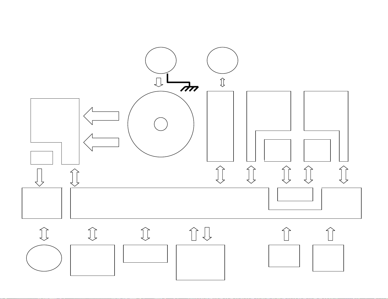
19. System Diagram
AC
Input
Cosman G4 Radiofrequency Generator Service Manual (SPI 11291 Rev A)
USB
RF Oscillator
Power Supply
Board
TC
Measurement
100V
Low Volts
Mains
Transformer
Backplane Board
USB
Output
Board
RMS
Stimulator
Board
RMS
Volts
Current
Measurement
Board
Low
Volts
Isolation
RF
Output w
TC
uP SOM
Board
PC/104 MIO
A/D D/A I/O
Display screen
w Touch panel
Section 19
On/Off
Buttons
Output
Control
Knob
Page 69

Cosman G4 Radiofrequency Generator Service Manual (SPI 11291 Rev A)
This page intentionally blank
Section 19
Page 70
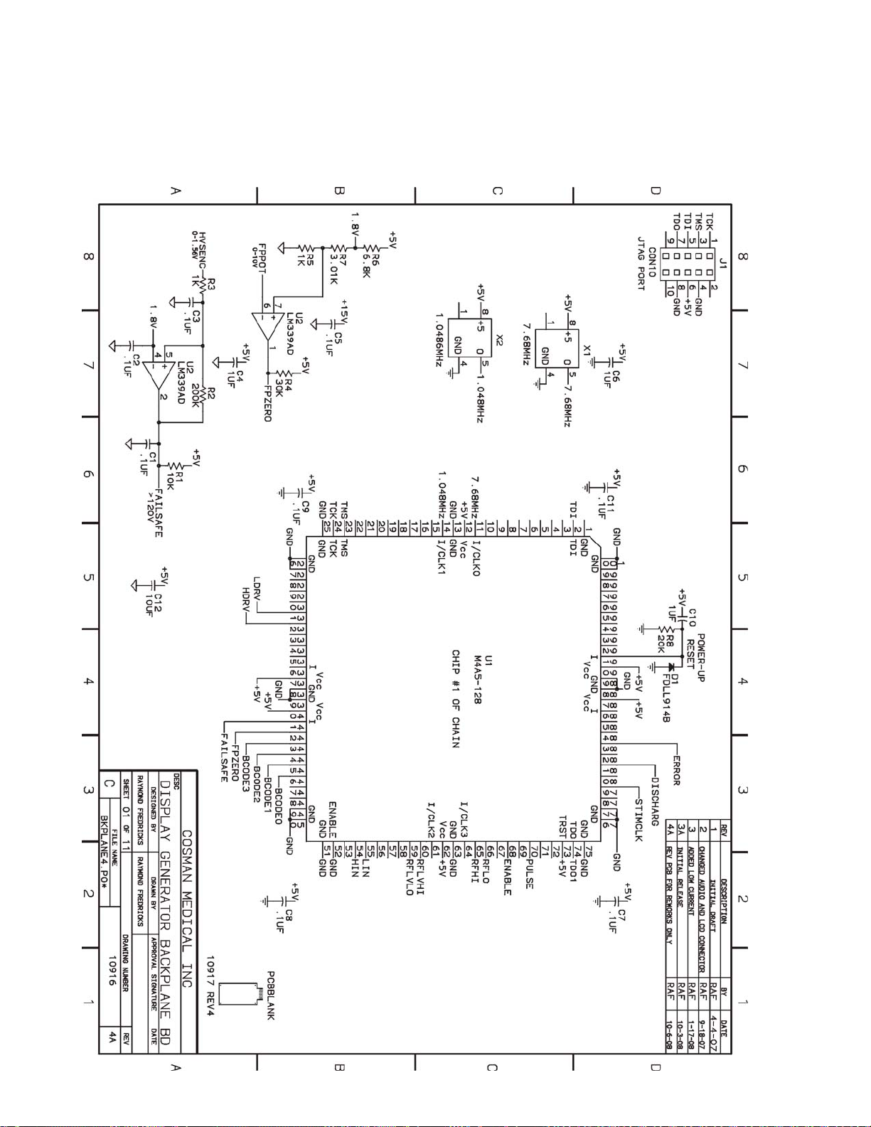
Cosman G4 Radiofrequency Generator Service Manual (SPI 11291 Rev A)
20. Schematic Drawings
20.1 Backplane Board Assembly
Section 20
Page 71
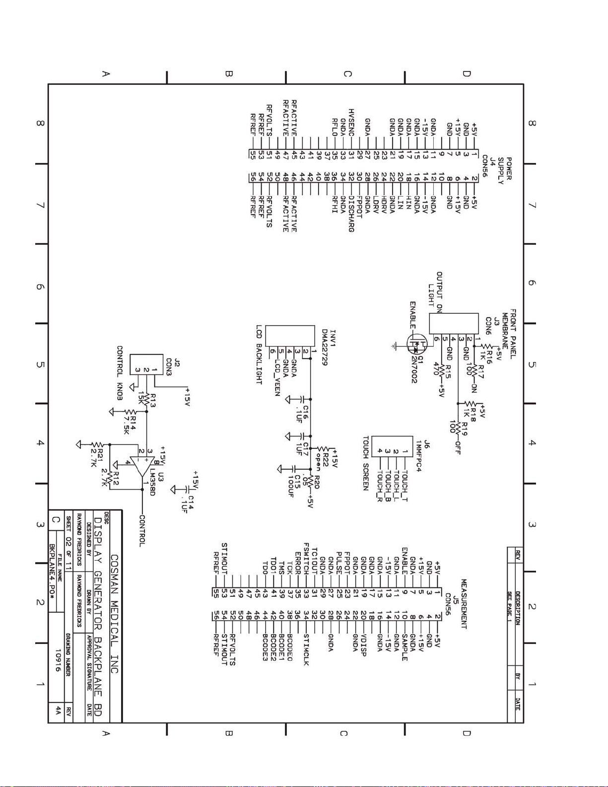
Cosman G4 Radiofrequency Generator Service Manual (SPI 11291 Rev A)
Section 20
Page 72
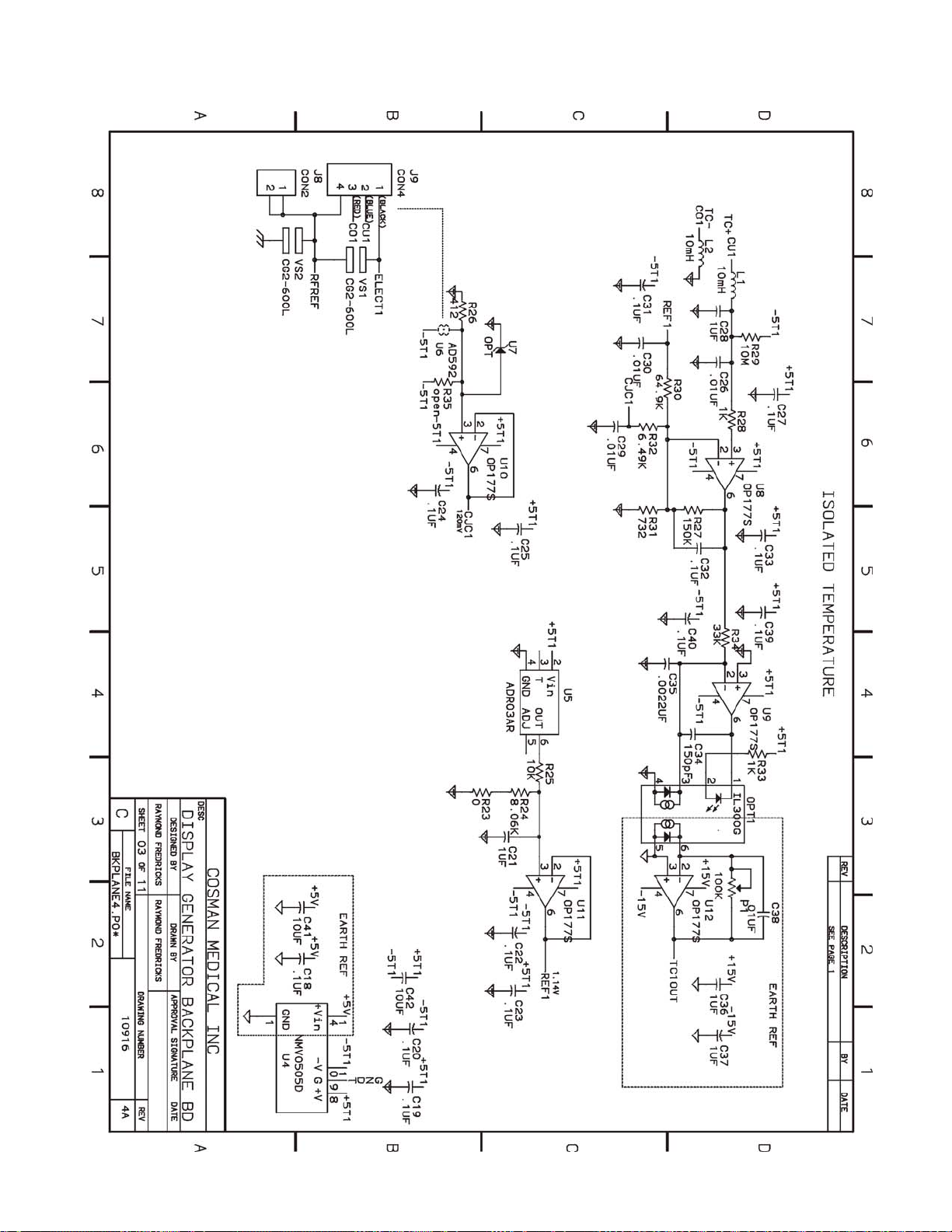
Cosman G4 Radiofrequency Generator Service Manual (SPI 11291 Rev A)
Section 20
Page 73
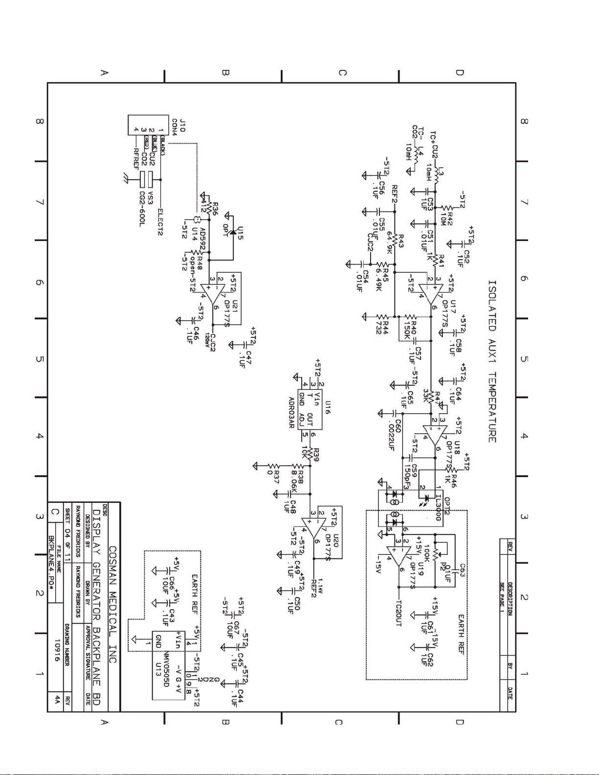
Cosman G4 Radiofrequency Generator Service Manual (SPI 11291 Rev A)
Section 20
Page 74
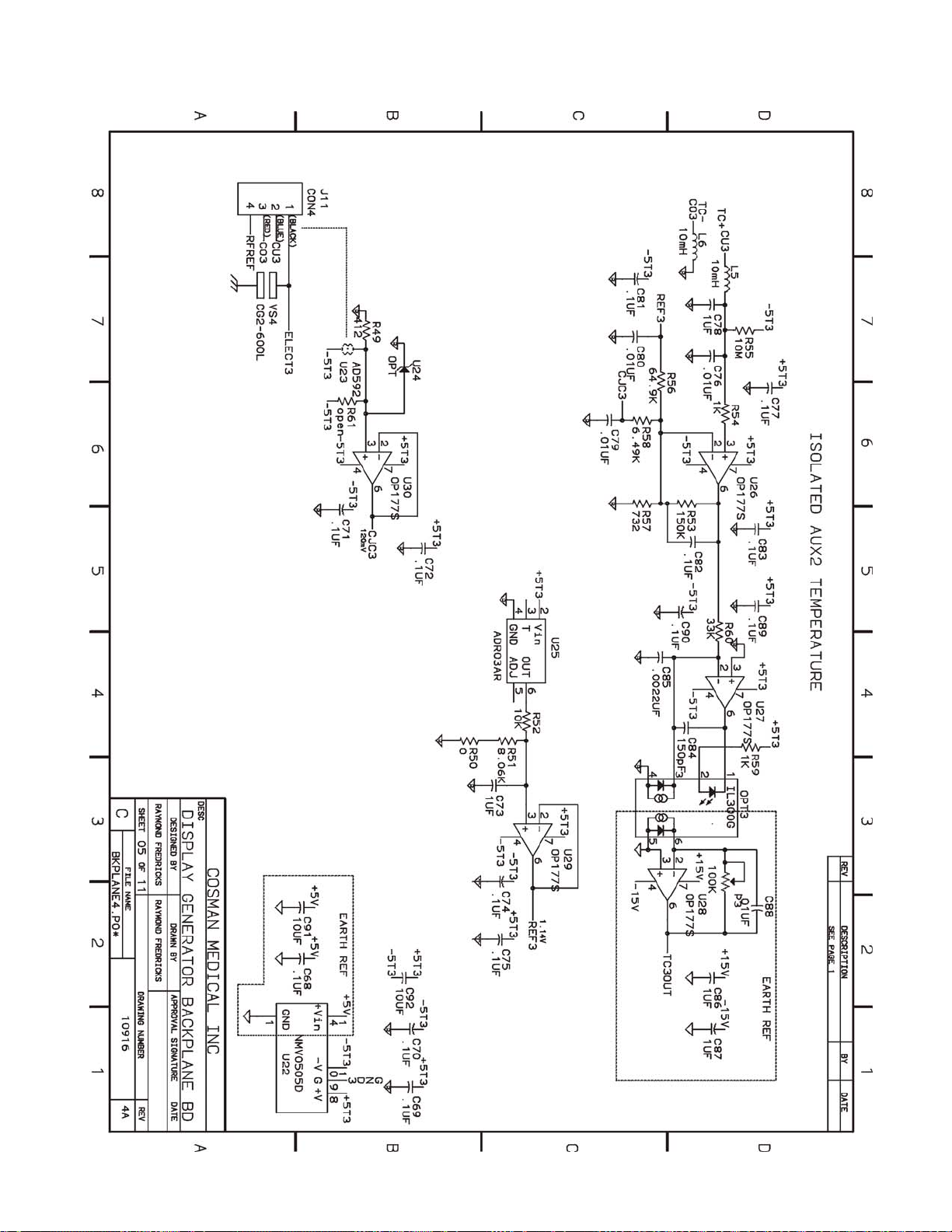
Cosman G4 Radiofrequency Generator Service Manual (SPI 11291 Rev A)
Section 20
Page 75
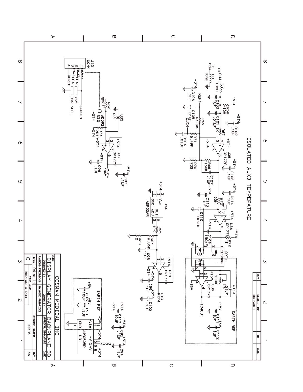
Cosman G4 Radiofrequency Generator Service Manual (SPI 11291 Rev A)
Section 20
Page 76
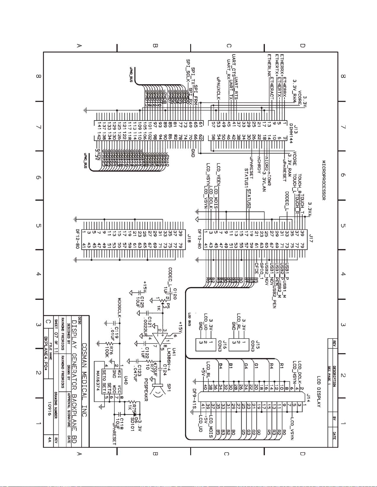
Cosman G4 Radiofrequency Generator Service Manual (SPI 11291 Rev A)
Section 20
Page 77
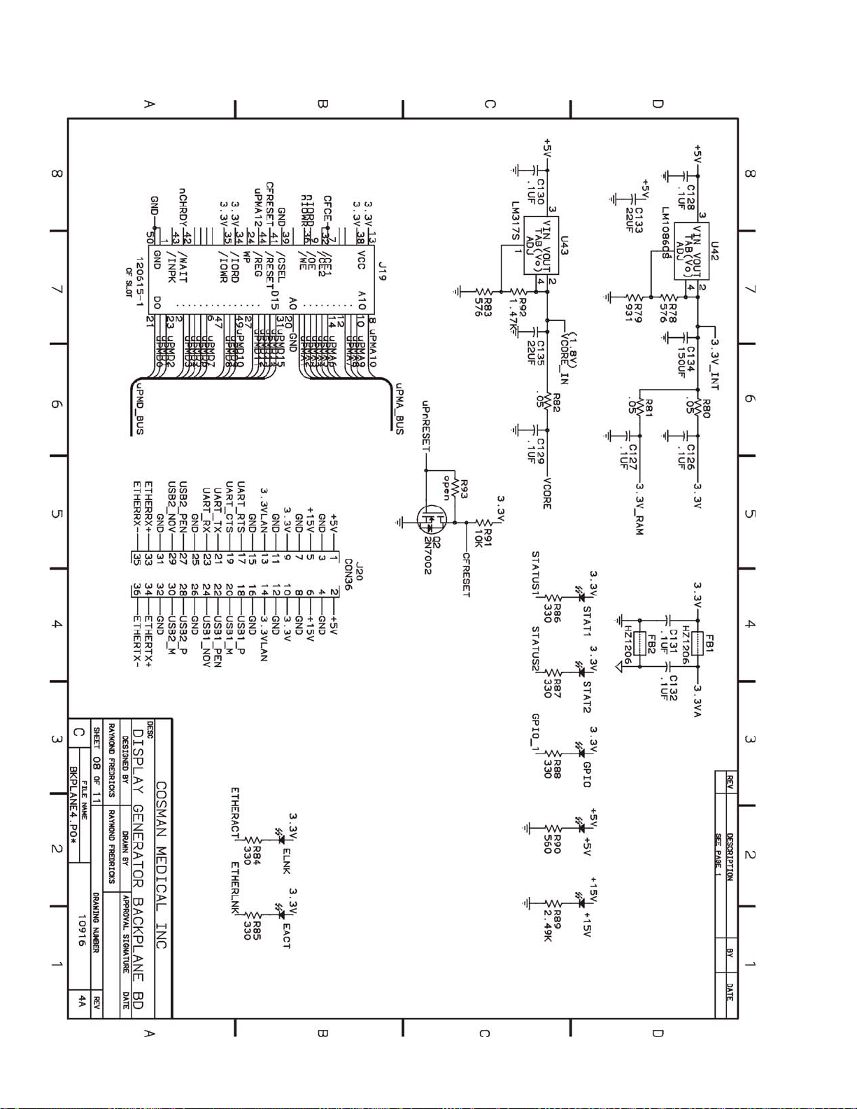
Cosman G4 Radiofrequency Generator Service Manual (SPI 11291 Rev A)
Section 20
Page 78
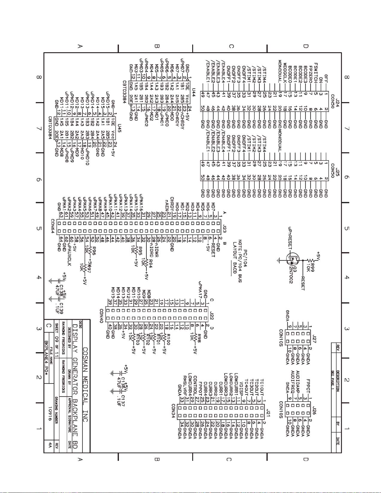
Cosman G4 Radiofrequency Generator Service Manual (SPI 11291 Rev A)
Section 20
Page 79
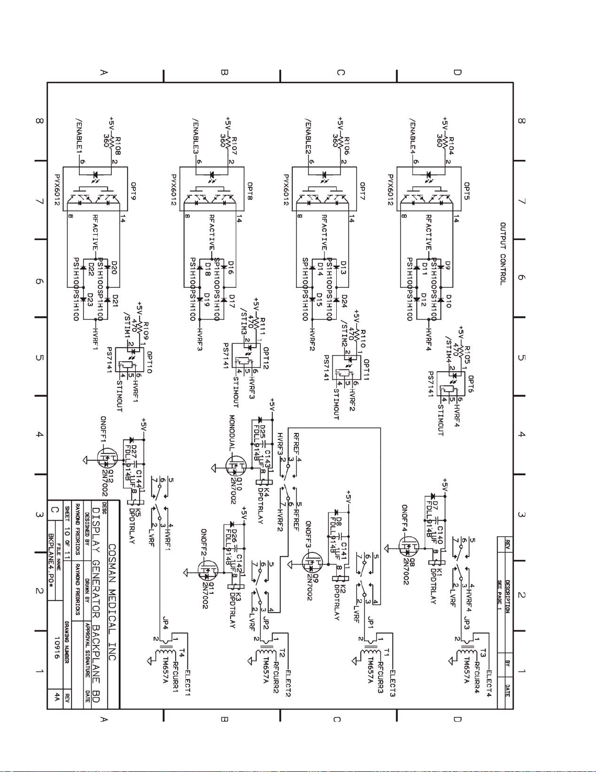
Cosman G4 Radiofrequency Generator Service Manual (SPI 11291 Rev A)
Section 20
Page 80
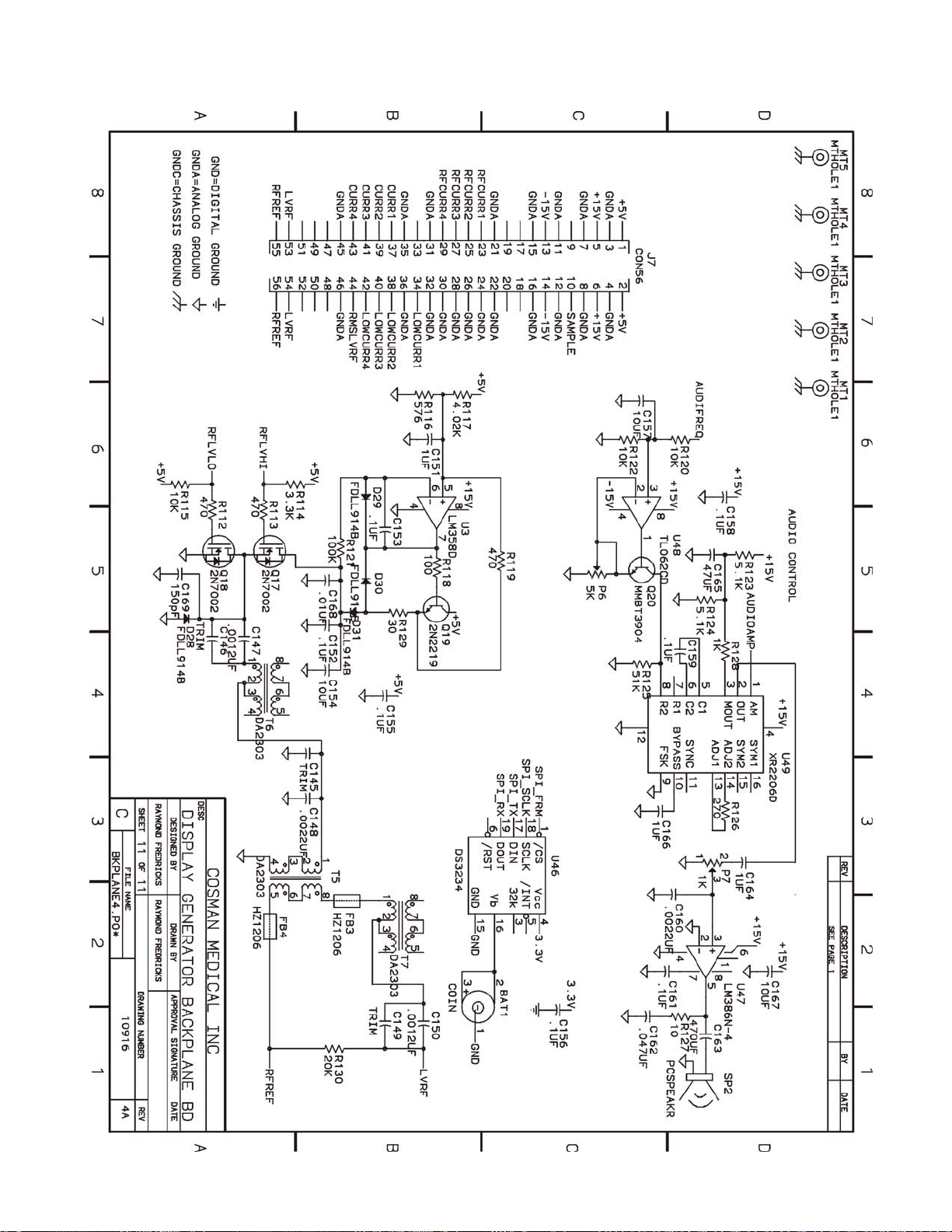
Cosman G4 Radiofrequency Generator Service Manual (SPI 11291 Rev A)
Section 20
Page 81
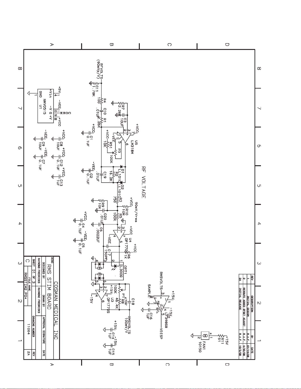
Cosman G4 Radiofrequency Generator Service Manual (SPI 11291 Rev A)
20.2 RMS Stim Board Assembly
Section 20
Page 82
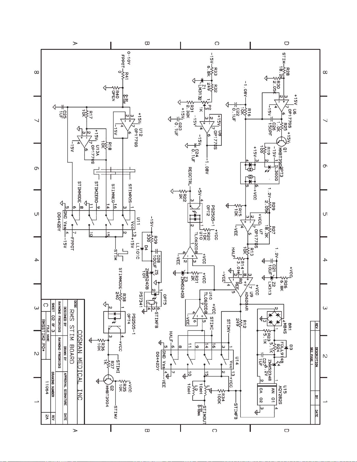
Cosman G4 Radiofrequency Generator Service Manual (SPI 11291 Rev A)
Section 20
Page 83
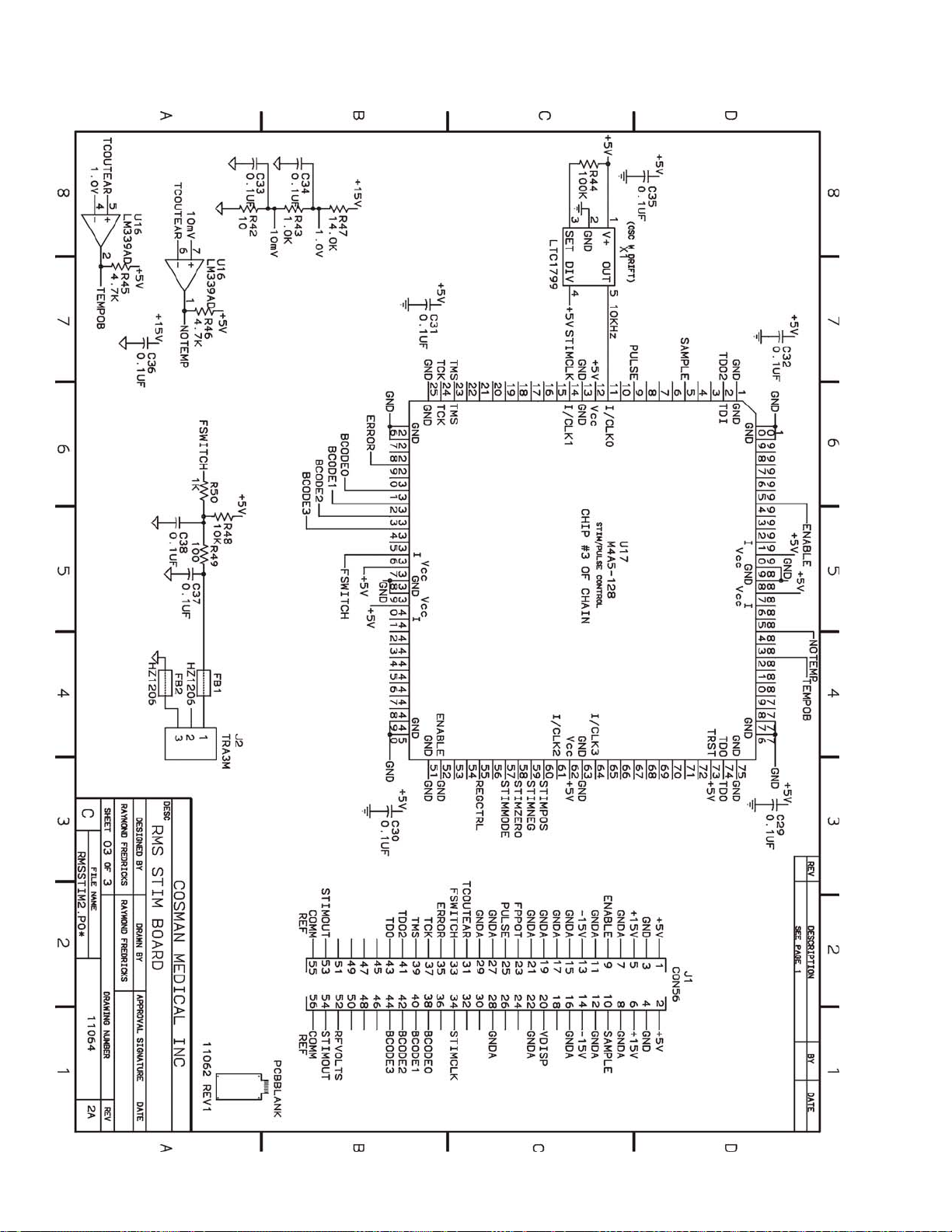
Cosman G4 Radiofrequency Generator Service Manual (SPI 11291 Rev A)
Section 20
Page 84
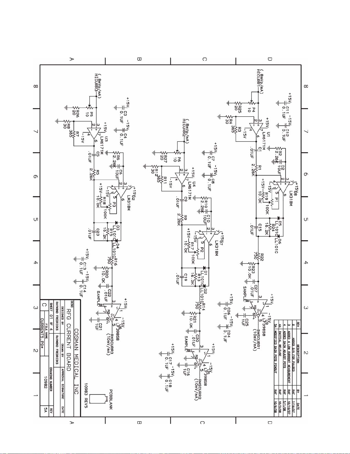
Cosman G4 Radiofrequency Generator Service Manual (SPI 11291 Rev A)
20.3 Current Board Assembly
Section 20
Page 85
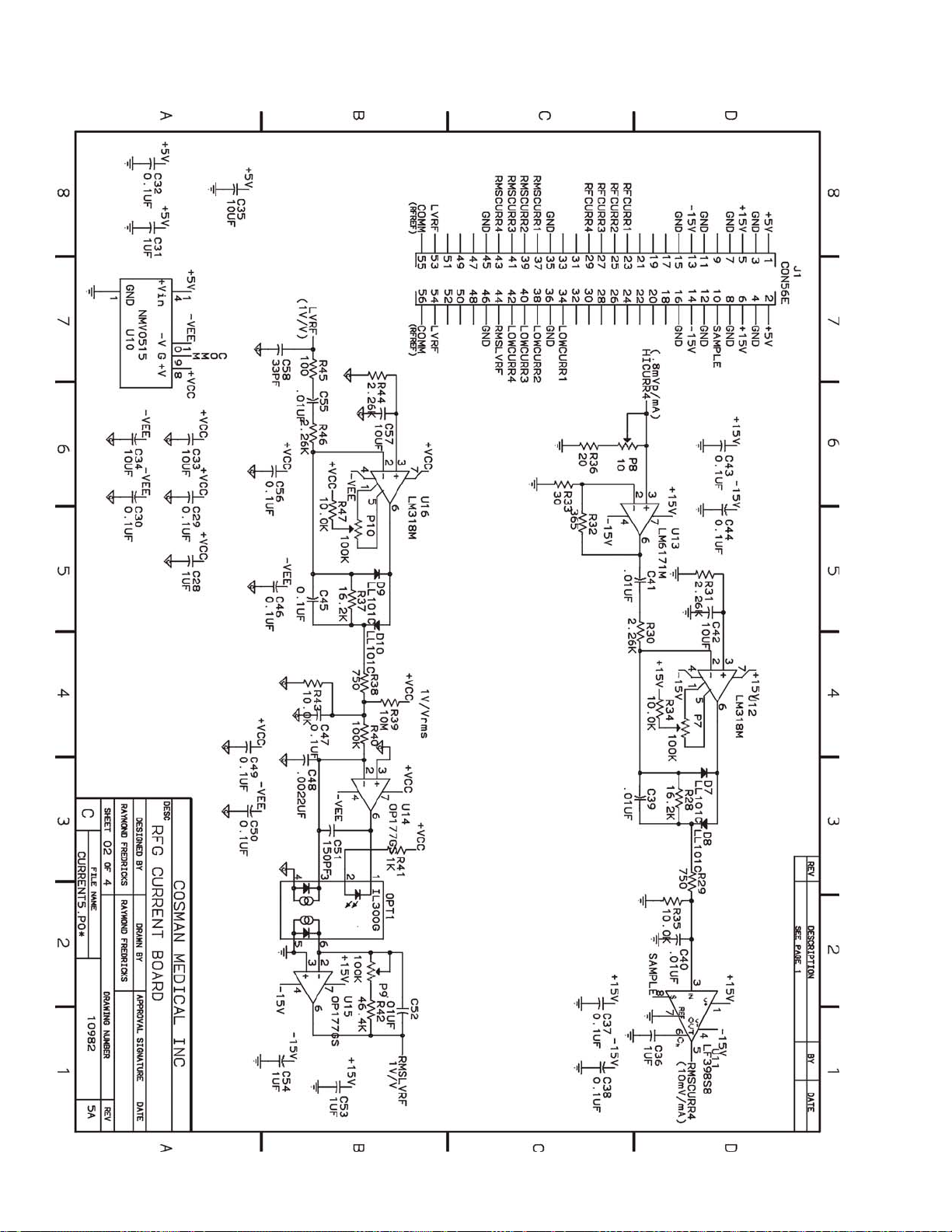
Cosman G4 Radiofrequency Generator Service Manual (SPI 11291 Rev A)
Section 20
Page 86
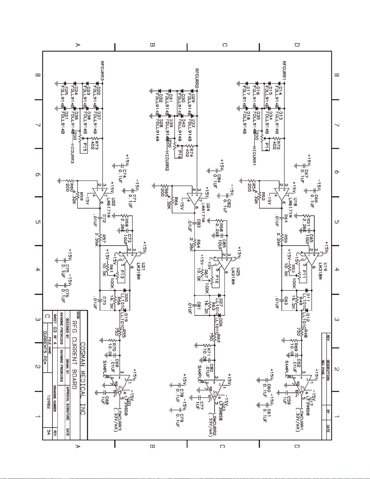
Cosman G4 Radiofrequency Generator Service Manual (SPI 11291 Rev A)
Section 20
Page 87
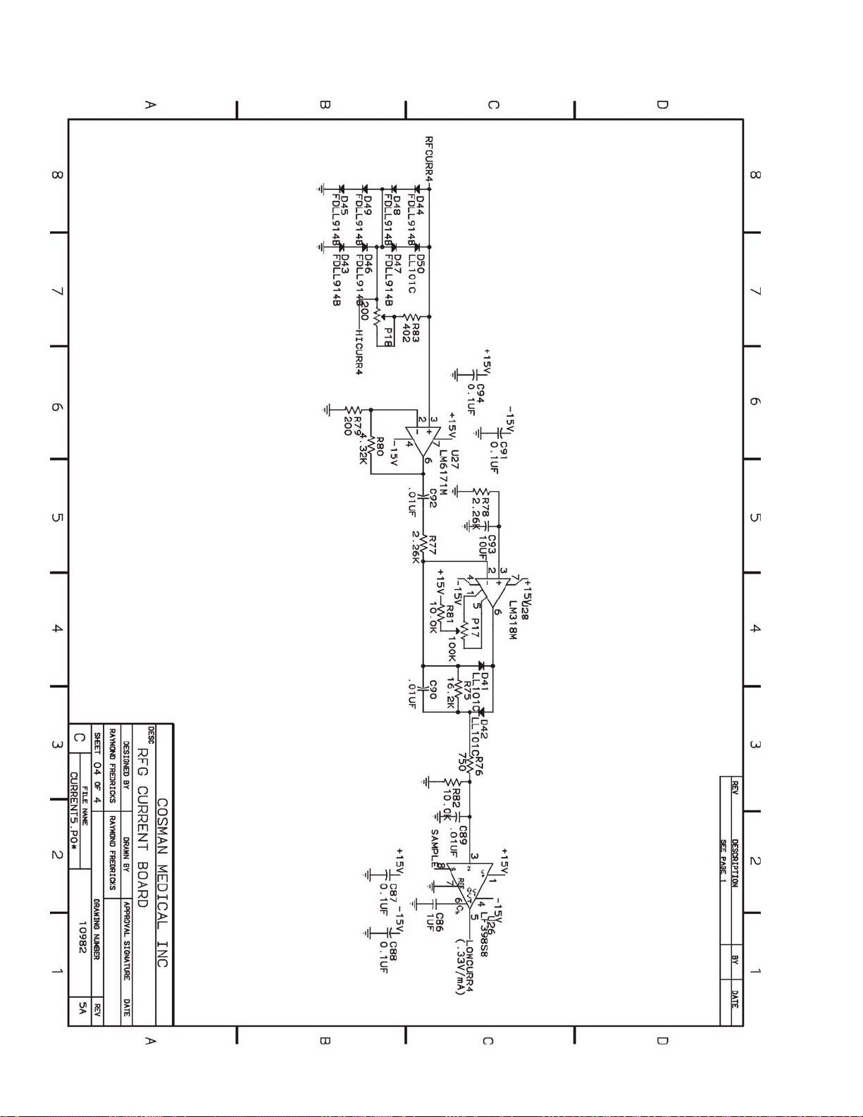
Cosman G4 Radiofrequency Generator Service Manual (SPI 11291 Rev A)
Section 20
Page 88
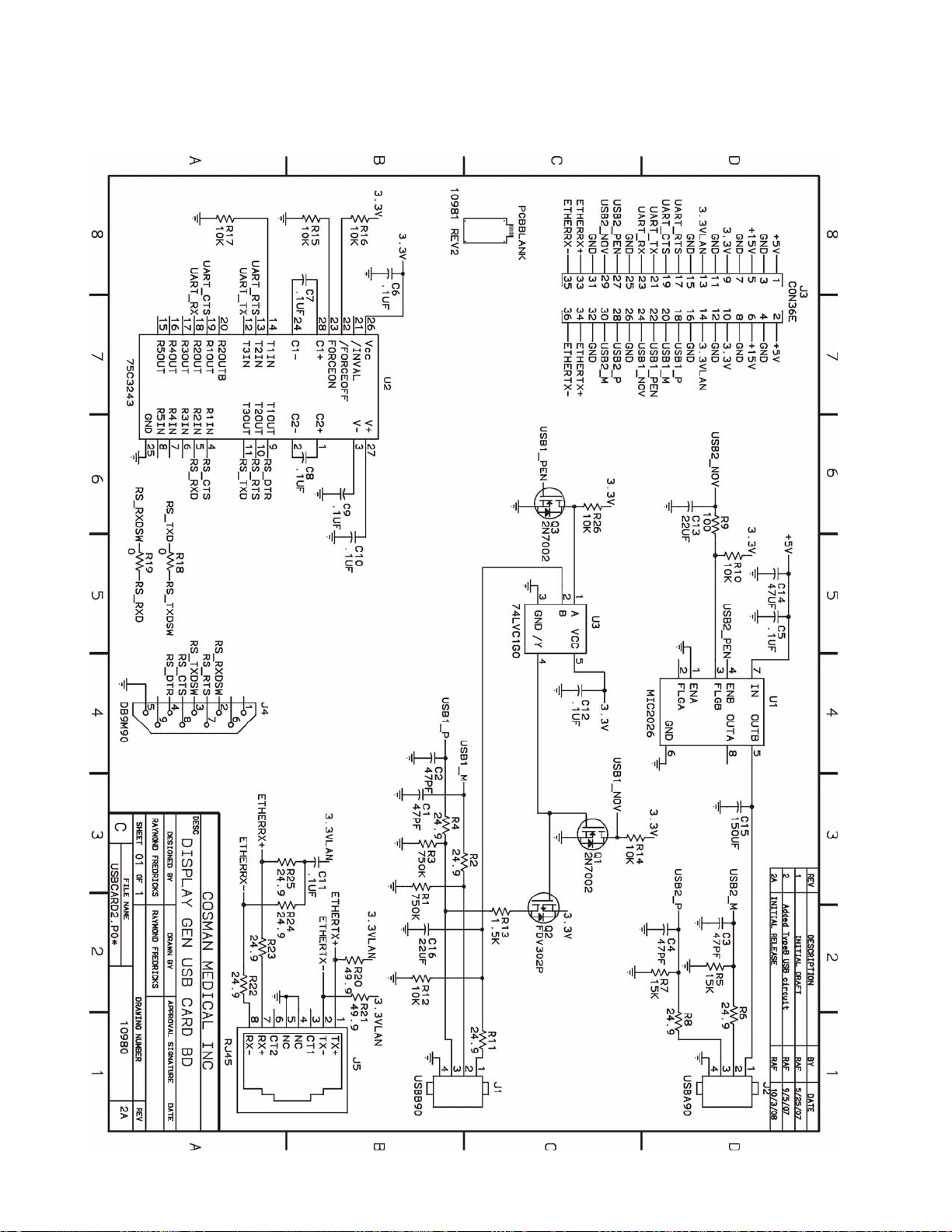
Cosman G4 Radiofrequency Generator Service Manual (SPI 11291 Rev A)
20.4 USB Card Board Assembly
Section 20
Page 89
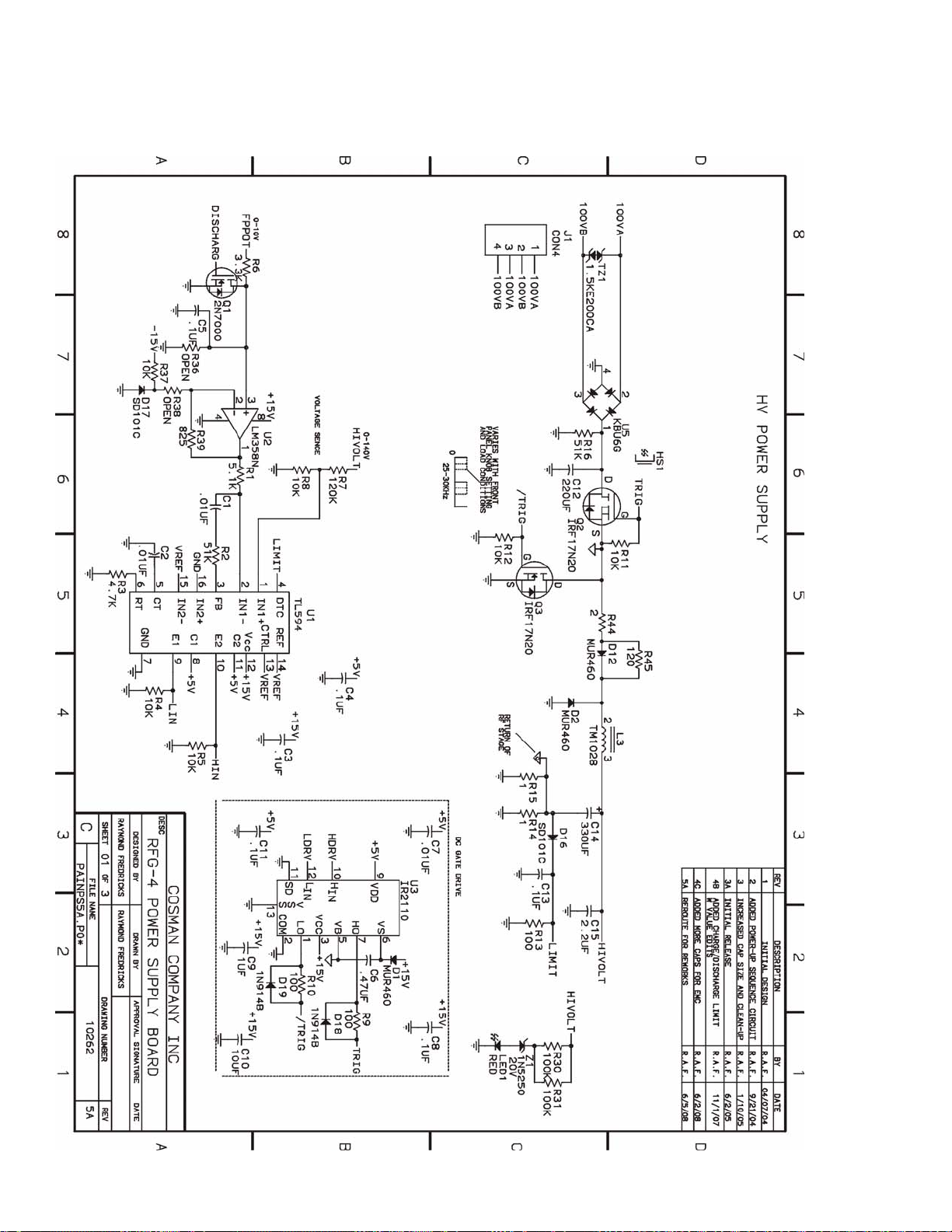
Cosman G4 Radiofrequency Generator Service Manual (SPI 11291 Rev A)
20.5 Power Supply Board Assembly
Section 20
Page 90
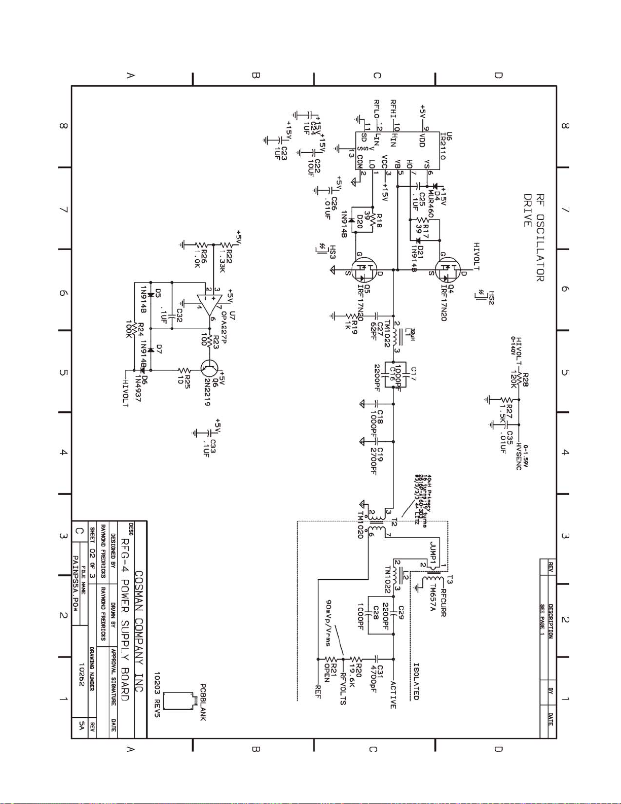
Cosman G4 Radiofrequency Generator Service Manual (SPI 11291 Rev A)
Section 20
Page 91
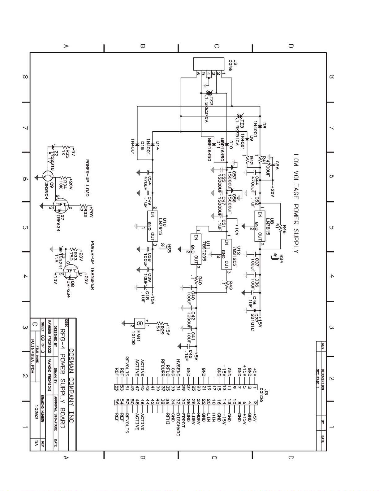
Cosman G4 Radiofrequency Generator Service Manual (SPI 11291 Rev A)
Section 20
Page 92
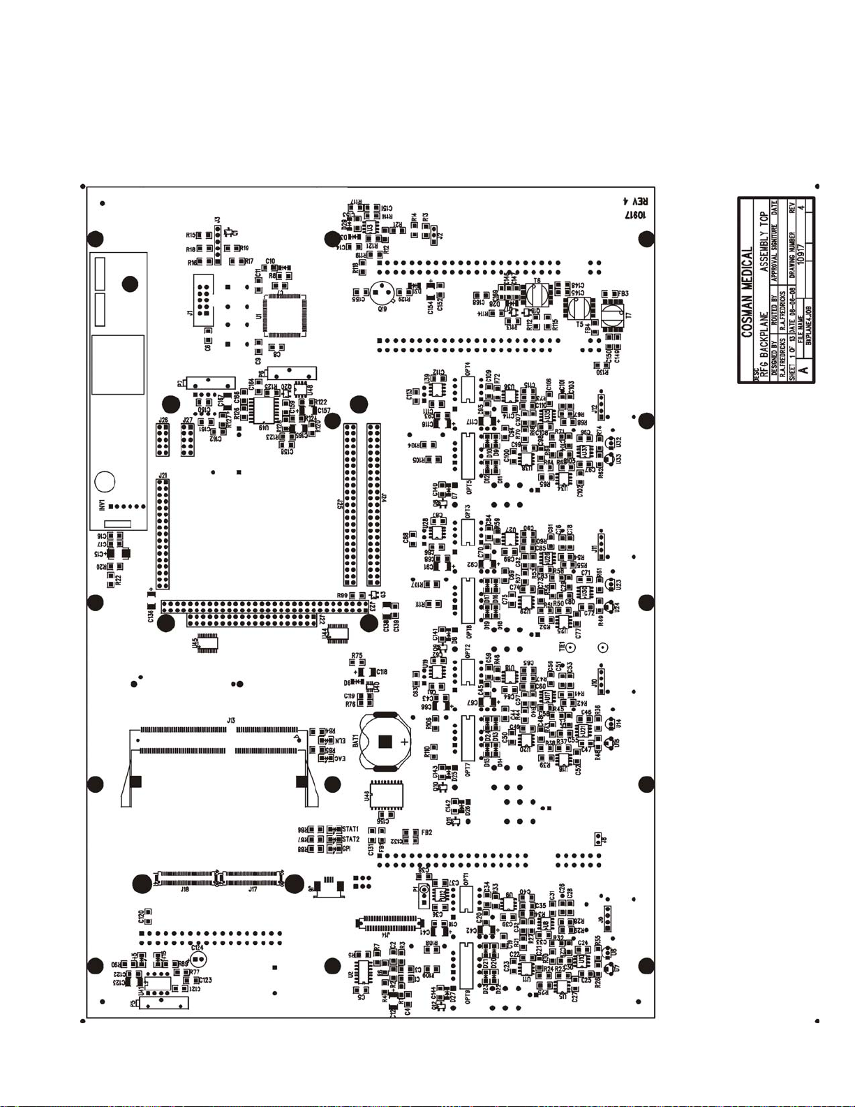
Cosman G4 Radiofrequency Generator Service Manual (SPI 11291 Rev A)
21. PC Board Assemblies
21.1 Backplane Board Assembly
21.1.1 Topside part placement
Section 21
Page 93
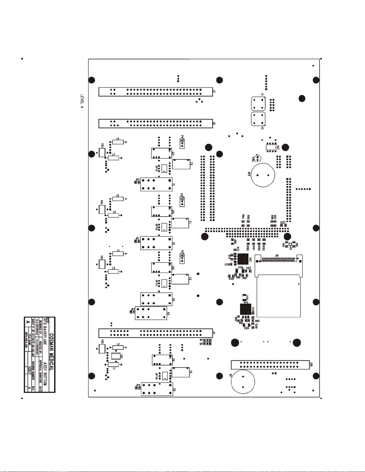
Cosman G4 Radiofrequency Generator Service Manual (SPI 11291 Rev A)
21.1.2 Bottomside part placement
Section 21
Page 94
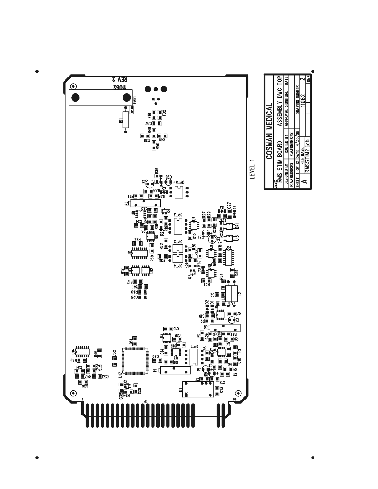
Cosman G4 Radiofrequency Generator Service Manual (SPI 11291 Rev A)
21.2 RMS Stim Board Assembly
21.2.1 Topside part placement
Section 21
Page 95
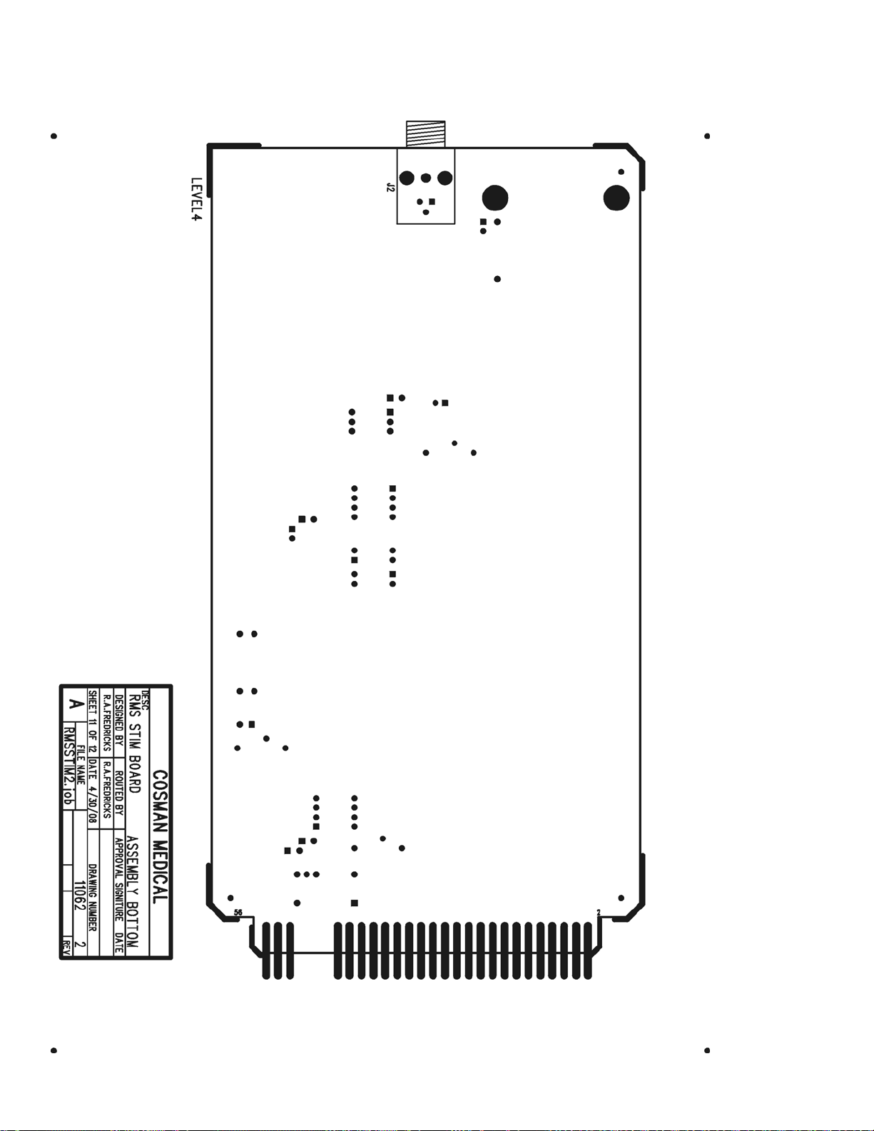
Cosman G4 Radiofrequency Generator Service Manual (SPI 11291 Rev A)
21.2.2 Bottomside part placement
Section 21
Page 96
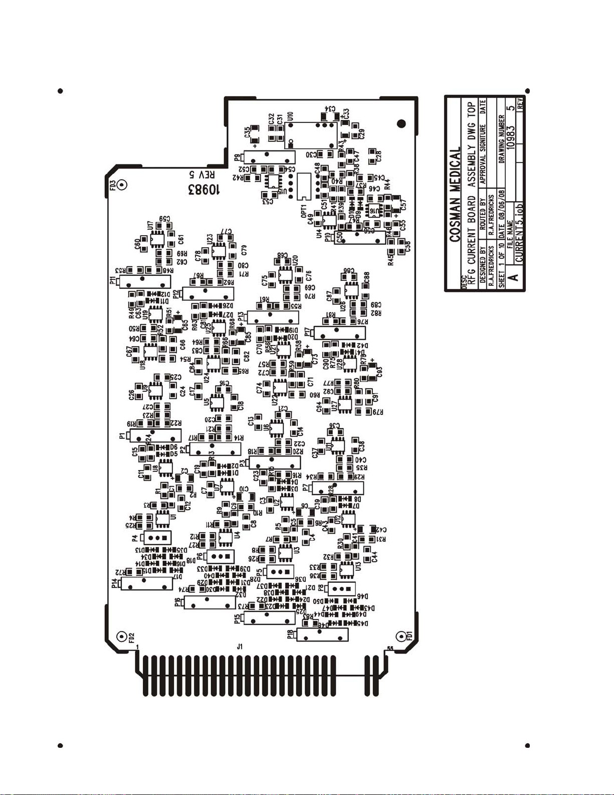
Cosman G4 Radiofrequency Generator Service Manual (SPI 11291 Rev A)
21.3 Current Board Assembly
Section 21
Page 97

Cosman G4 Radiofrequency Generator Service Manual (SPI 11291 Rev A)
This page intentionally left blank
Section 21
Page 98
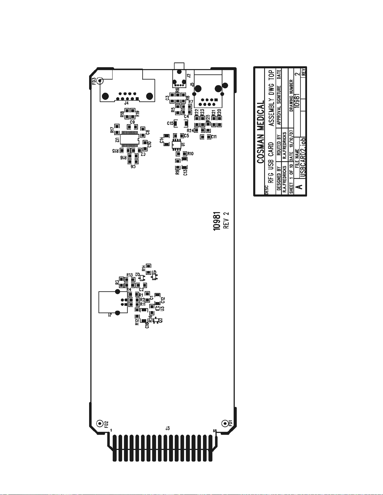
Cosman G4 Radiofrequency Generator Service Manual (SPI 11291 Rev A)
21.4 USB Card Board Assembly
Section 21
Page 99

Cosman G4 Radiofrequency Generator Service Manual (SPI 11291 Rev A)
This page intentionally left blank
Section 21
Page 100
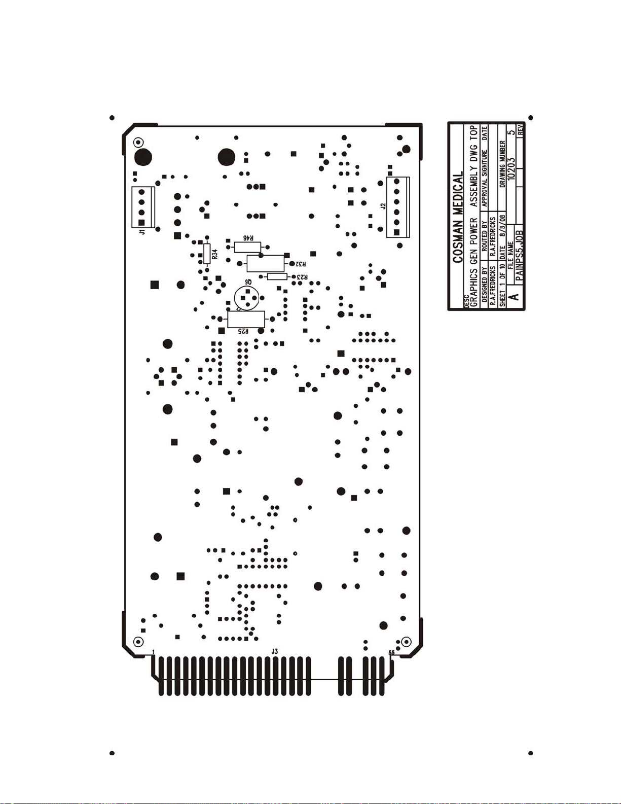
Cosman G4 Radiofrequency Generator Service Manual (SPI 11291 Rev A)
21.5 Power Supply Board Assembly
21.5.1 Topside part placement
Section 21
 Loading...