

Page 1

Basic Characteristics Data
Basic Characteristics Data
Model Circuit method
Input module of
RBC200F
Active filter 40 - 220 2.4 *1 Relay FR-4 - Ye s No No
Switching
frequency
[kHz]
Input
current
[A]
Inrush
current
protection
Material
PCB/Pattern
Single
sided
Double
sided
Series/Parallel
operation availability
Series
operation
Parallel
operation
Output module of
Y, Z
Output module of
G, H, J, K, L
Output module of
M, P, Q
*1 The value at ACIN 100V and 200W output.
Ser
*2
ies operation is possible only if Slot 2 and Slot 3 are the same module. (Refer to Instruction Manual 3.1)
LLC resonant converter 90 - 180 - - FR-4 - Ye s No No
Flyback converter 60 - 120 - - FR-4 - Ye s Yes *2 No
Flyback converter 60 - 120 - - FR-4 - Ye s No No
RB-6
Page 2
AC-DC Power Supplies Congurable Type
Instruction Manual
1
Conguration - Model Name Construction
Function
2
2.1 Input voltage range
2.2 Inrush current limiting
2.3 Overcurrent protection
2.4 Overvoltage protection
2.5 Output voltage adjustment range
2.6 Output ripple and ripple noise
2.7 Isolation
2.8 Start/stop sequence
3
Series Operation and Parallel Operation
3.1 Series Operation
3.2 Parallel Operation
4 Assembling and Installation Method
4.1 Heat dissipation (derating)
4.2 Installation method
4.3 Mounting screw
4.4 Ground
4.5 Expectancy life and warranty
RB-8
RB-9
RB-9
RB-9
RB-9
RB-9
RB-9
RB-9
RB-9
RB-9
RB-10
RB-10
RB-10
RB-10
RB-10
RB-11
RB-11
RB-11
RB-11
5 Option and Others
5.1 Outline of options
5.2 Others
RB-12
RB-12
RB-13
RB-7
Page 3
3
2
1
AC-DC Power Supplies Congurable Type
1
Conguration - Model
Name Construction
The RB series has Order Name which is used for the ordering
aside from Model Name. Please order at Orderer Name.
The Order Name will be assigned after the product is congured.
Please contact us for further details.
Model Name Construction
¡
RB C F
Series name
1
RB=RB series
Multiple output
2
Abbreviation maximum output power
3
200=207W
Universal input
4
Slot 3 module code
5
Slot 2 module code
6
Slot 1 module code
7
Optional code
8
5 6 7 841 32
Instruction Manual
Conguration rules
¿
(1) The code of the module installed in Slot 1 is selected from Slot
1 output module specications.
(2) Slot 1 has to have a module selected.
(3) The code of the module installed in Slot 2 is selected from Slot
2, Slot 3 output module specifications and Slot 2 dedicated
output module.
(4) The code of the module installed in Slot 3 is selected from Slot
2, Slot 3 output module specications.
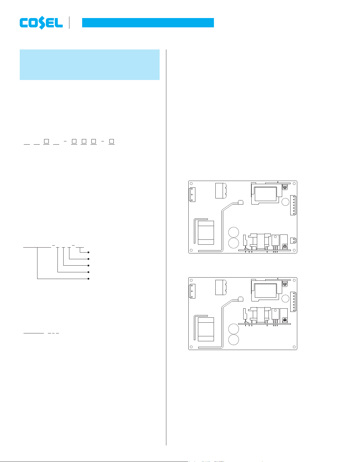
(5) It is possible to congure Slot 2, Slot 3 as an empty slot. (Refer
to Fig.1.1, Fig1.2)
If you do not install a module, code “O” (blank code) should be
selected.
However, It is not possible to congure both Slot 2 and 3 as “O”.
If you congure Slot 2 as “O” , pin no.5 to 7 of CN2 is NC.
If you congure Slot 3 as “O” , CN3 is not installed.
(6) Series operation is possible only if Slot 2 and Slot 3 are the
same module. Please refer to section 3.1
<Model Name Example>
RBC 200 F K YJ
Order Name Construction
¡
1 through 7 have the same rules as Model Name, after that add
management alphanumeric character (6 digits).
Optional codes are not listed on Order Name.
<Order Name Example>
RBC200F - K J Y - 1 2 3 4 5 6
“1 2 3 4 5 6” is an example of management alphanumeric charac-
ter.
Output of slot
¡
Slot 1 output is connected to +V1, G1.
Slot 2 output is connected to +V2, -V2 and G2.
Slot 3 output is connected to +V3, G3.
SN
with Chassis & cover
Slot 1 Module Y (24V 6A)
Slot 2 Module J (12V 2.5A)
Slot 3 Module K (16.5V 1.9A)
RB series 207W (RBC200F)
Fig.1.1 Schematic, if you congure Slot 2 as “O”
(Model Name : RBC200F-OOO)
Fig.1.2 Schematic, if you congure Slot 3 as “O”
(Model Name : RBC200F-OOO)
RB-8
Page 4

AC-DC Power Supplies Congurable Type
2 Function
2.1 Input voltage range
The range is from AC85V to AC264V. (please see SPECIFICA-
¡
TIONS for details).
In cases that conform with safety standard, input voltage range is
¡
AC100 - AC240V (50/60Hz).
If input value doesn’t fall within above range, the unit may not op-
¡
erate in accordance with specications and/or start hunting or fail.
If you need to apply a square waveform input voltage, which is
commonly used in UPS and inverters, please contact us.
When the input voltage changes suddenly, the output voltage ac-
¡
curacy might exceed the specication. please contact us.
2.2 Inrush current limiting
An inrush current limiting circuit is built-in.
¡
If you need to use a switch on the input side, please select one
¡
that can withstand an input inrush current.
Relay technique is used in the inrush current limiting circuit. When
¡
you turn the power ON/OFF repeatedly within a short period of
time, please have enough intervals so that the inrush current limit-
ing circuit becomes operative.
Surge current in the lter unit does not include (0.2ms or less).
¡
2.3 Overcurrent protection
An overcurrent protection circuit is built-in and activated at 105%
¡
of the rated current. A unit automatically recovers when a fault
condition is removed.
Please do not use a unit in short circuit and/or under an overcur-
rent condition.
Intermittent Operation Mode
¡
Intermittent operation for overcurrent protection is included in a
part of series. When the overcurrent protection circuit is activated
and the output voltage drops to a certain extent, the output be-
comes intermittent so that the average current will also decrease.
Output voltage shuts down when the output voltage continuously
¡
drops due to overcurrent protection.
Output voltage recovers from overcurrent protection by shutting
¡
down the input voltage and waiting more than 3 minutes then turn-
ing on AC input again.
2.4 Overvoltage protection
An overvoltage protection circuit is built-in. If the overvoltage pro-
¡
tection circuit is activated, shut down the input voltage, wait more
than 3 minutes and turn on the AC input again to recover the out-
put voltage.
Remarks :
Please avoid applying a voltage exceeding the rated voltage to an
output terminal. Doing so may cause a power supply to malfunc-
tion or fail. If you cannot avoid doing so, for example, if you need
to operate a motor, etc., please install an external diode on the
output terminal to protect the unit.
Instruction Manual
2.5 Output voltage adjustment range
To increase an output voltage, turn a built-in potentiometer clock-
¡
wise.
To decrease the output voltage, turn it counterclockwise.
2.6 Output ripple and ripple noise
Output ripple noise may be inuenced by measurement environ-
¡
ment, measuring method Fig.2.1 is recommended.
+V1
C
1
+
G1
150mm
Osiloscope/
Ripple noise meter
Bw:20MHz
C1 : Aluminum electrolytic capacitor 22μF
Fig.2.1 Measuring method of Ripple and Ripple Noise
(Example of measurement with V1)
Remarks :
When GND cable of probe with ux of magnetic force from power
supply are crossed, ripple and ripple noise might not measure cor-
rectly.
Please note the measuring environment.
Bad example Good example
Fig.2.2 Example of measuring output ripple and ripple noise
Differential probe
2.7 Isolation
For a receiving inspection, such as Hi-Pot test, gradually increase
¡
(decrease) the voltage for the start (shut down). Avoid using Hi-
Pot tester with the timer because it may generate voltage a few
times higher than the applied voltage, at ON/OFF of a timer.
When you test a unit for isolation between the input and output, or
¡
between output and terminal FG, short-circuit between all outputs
and function terminal.
When you test a unit for isolation between output V1,V2, and out-
¡
put V3,short-circuit between output V1 and output V2.
2.8 Start/stop sequence
The start / stop waveform changes due to external capacity, load
¡
current, etc, so please evaluate if start / stop sequence is required.
Please contact us if start / stop sequence is required.
¡
Load
RB-9
Page 5

(1) B, D
(1) A
(2) A - F
AC-DC Power Supplies Congurable Type
3 Series Operation and
Parallel Operation
3.1 Series Operation
Series operation is possible only if Slot 2 and Slot 3 are the same
¡
module. Fig.3.1 shows an example of wiring.
Remarks :
Please be sure to have enough cooling in case one of the slots
stops due to activation of the protection circuitry.
In case of malfunction (Failure of protection circuit activation),
please stop the operation.
The combined output voltage of series operation is 48 V.
If the combined output voltage exceeds 60V, the safety agency
approvals are void.
Instruction Manual
Ik × V
A
k =
(Rated output power of k-th module)
Rated output power : Depends on input (refer to Fig.4.3)
Load factor [%] = maximum value of A
Ik, Vk : output current, voltage
* When the k-th slot is module P, Q, V
and -V.
Test Measuring points
¡
Be aware of the conductive parts during the measurements.
Please contact us for more detail.
<Module G, H, J, K, L, M> <Module P, Q>
k
to A
1
3
is the voltage between +V
k
23 5 2
+V1
G1
+V2
G2
+V3
G3
Load
Load
RBC200F
+V1
G1
+V2
G2
+V3
G3
(a) (b)
RBC200F
Load
Fig.3.1 Examples of wiring in series operation
3.2 Parallel Operation
Parallel operation and redundancy operation are not possible.
¡
4 Assembling and
Installation Method
4.1 Heat dissipation (derating)
For reliable and safe operation, please make sure the maximum
¡
component temperature rise given in table 4.1 is not exceeded.
Please refer to Fig.4.2 for derating information based on each
mounting methods.
Please allow enough ventilation for the power supply.
Temperature of points 1 through 5 should be lower than the up-
per limit temperature.
The expectancy life in the upper bound temperature (Points 1
through 5) is 3 years or more. Please refer to 4.5 if you want to
extend the longevity.
Derating curve depending on input voltage
¡
Derating curve depending on input voltage is shown in Fig.4.3.
The definition of load factor is the following, suffix k means the
¡
k-th slot.
1 4
34 5
1
4
Fig.4.1 Measurement points locations
Table 4.1 Maximum temperature of measurement points
Installation
condition
A
B
C
D
E
F
A,B,C,
D,E,F
Cooling
Method
Convection
Forced air
100
80
70
60
40
Load factor [%]
20
0
-20-
Load factor
75%<Po[100%
Po[ 75%
75%<Po[100%
Po[ 75%
75%<Po[100%
Po[ 75%
75%<Po[100%
Po[ 75%
75%<Po[100%
Po[ 75%
75%<Po[100%
Po[ 75%
75%<Po[100%
Po[ 75%
(1) Convection
(2) Forced air (0.5m
10 0 10 20 30
Maximum temperature [C]
:
: V1
: V2
1
Capacitor
2
Capacitor
3
Capacitor
: V3
4
Capacitor
81 79 80 79 90
86 84 84 84 93
66 72 75 70 85
78 81 84 80 92
70 61 73 79 83
78 73 81 83 89
73 66 68 67 78
81 77 79 78 87
68 72 81 79 91
75 80 84 83 93
65 67 74 72 84
79 79 84 82 92
79 82 83 80 83
82 82 83 80 83
mounting
mounting
mounting
(1) F
(1) F
mounting
mounting
(1) C, E
(1) C, E
mounting
mounting
3
/min)
40 50 60 70
35 65
: V2
5
Capacitor
Ambient temperature [℃]
*
Specifications for ripple and ripple noise changes in the shaded area.
Fig.4.2 Derating curve depends on ambient temperature (Reference value)
RB-10
Page 6

Case
88
AC-DC Power Supplies Congurable Type
100
80
Load factor [%]
85 90
Input voltage [VAC]
Fig.4.3 Derating curve depends on input voltage
Instruction Manual
There is a possibility that it is not possible to cool enough when
¡
the power supply is used by the sealing up space as showing in
Figure 4.6.
Please use it after conrming the temperature of points 1 through
of section 4.1.
5
Power Supply
Fig.4.6 Installation example
4.2 Installation method
Mounting method
¡
(A) (B) (C)
CN1
CN1
Standard Position
(D)
CN1
CN1
Fig.4.4 Mounting method
This power supply is manufactured by SMD technology.
¡
Do not touch any SMD components on the unit. Be especially
careful when handling.
If using a metal chassis, keep proper insulation between the
¡
component and metal chassis, use the spacer of 10mm or more
between bottom of power supply and metal chassis.
If d1 and/or d2 are less than the value mentioned in Fig.4.5, insert
an insulating sheet with reinforced insulation between the power
supply unit and metal chassis.
The following distance is not satisfactory for cooling condition.
Please refer to section 4.1 for cooling method.
CN1
(F)(E)
CN1
4.3 Mounting screw
The mounting screw should be M3. The hatched area shows the
¡
allowance of metal parts for mounting.
FG
8 8
CN1
8
8
Fig.4.7 Allowance of metal for mounting
If the power supply unit is xed with metal parts from the top side,
¡
make sure not to make contact with any components on the unit.
This power supply is manufactured by SMD technology.
¡
The stress to PCB like twisting or bending causes defects to the
unit, so handle the unit with care.
CN2
CN3
8
8
4.4 Ground
When installing the power supply with your unit, ensure that the
¡
input FG terminal or mounting hole FG is connected to safety
ground of the unit. However when applying the safety agency,
connect the input FG terminal to safety ground of the unit.
It is recommended to electrically connect FG to metal chassis for
*
reducing noise.
d
2
CN1
d1=10mm min
d
2
d
2
CN1
d
2
Fig.4.5 Installation method
d
2
d2=6mm min
4.5 Expectancy life and warranty
Expectancy life
¡
Table 4.2 Expectancy life
Installation
condition
A
B,D
C,E
F
A,B,C,D,E,F
Remarks :
Estimated life expectancy can be calculated by point temperature
through 5 shown in section 4.1. Please contact us for details.
1
Cooling
Method
Convection
Forced air
Average ambient
temperature (yearly)
Ta=40C or less 6 6
Ta=50
C
Ta=30C or less 6 6
Ta=40
C
Ta=25C or less 6 6
Ta=35
C
Ta=20C or less 6 6
Ta=30
C
Ta=50C or less 6 6
Ta=60
C
Expectancy Life [years]
Po[75%75%<Po[100
6 4
6 4
6 4
6 4
6 4
%
RB-11
Page 7

(1) B, D
(1) A
(2) A - F
AC-DC Power Supplies Congurable Type
Instruction Manual
Warranty
¡
Table 4.3 Warranty
Installation
condition
A
B,D
C,E
F
A,B,C,D,E,F
Cooling
Method
Convection
Forced air
Average ambient
temperature (yearly)
Ta=40C or less 5 5
Ta=50
C
Ta=30C or less 5 5
Ta=40
C
Ta=25C or less 5 5
Ta=35
C
Ta=20C or less 5 5
Ta=30
C
Ta=50C or less 5 5
Ta=60
C
Warranty [years]
Po[75%75%<Po[100
5 3
5 3
5 3
5 3
5 3
5 Option and Others
5.1 Outline of options
Please contact us for details of specications and delivery timing.
*
You can combine multiple options. Some options, however, can-
*
not be combined with other options. Please contact us for details.
-C
¿
Option -C units have coated internal PCB for better moisture
-
resistance. The Input connector is hibox type (Mfr. J.S.T.).
Table 5.1 Coated internal PCB type
I/O Connector Part No. Connector type
Input connector CN1
Output connector
CN2
CN3
Function connector (optional) CN4 PH (hibox type
VH (hibox type
Table 5.3 Maximum temperature of measurement points
(RBC200F-O-SN)
%
Installation
condition
A
B
C
D
E
F
A,B,C,
D,E,F
Cooling
Method
Convection
Forced air
100
80
70
60
40
Load factor [%]
20
0
-20-
Load factor
75%<Po[100%
Po[ 75%
75%<Po[100%
Po[ 75%
75%<Po[100%
Po[ 75%
75%<Po[100%
Po[ 75%
75%<Po[100%
Po[ 75%
75%<Po[100%
Po[ 75%
75%<Po[100%
Po[ 75%
(1) Convection
(2) Forced air (0.5m
10 0 10 20 30
Maximum temperature [C]
:
: V1
: V2
1
Capacitor
2
Capacitor
3
Capacitor
: V3
4
Capacitor
83 76 77 75 86
83 76 77 77 86
73 72 75 70 84
79 78 80 78 88
77 61 73 81 82
81 70 78 80 85
79 66 67 67 77
84 73 76 75 84
75 72 83 81 92
77 76 81 80 90
67 62 69 67 79
76 71 76 74 83
74 77 79 75 79
72 75 76 73 76
mounting
mounting
mounting
(1) F
(1) F
mounting
mounting
(1) C, E
(1) C, E
mounting
mounting
3
/min)
40 50 60 70
35 55 65
: V2
5
Capacitor
Ambient temperature [℃]
*
Specifications for ripple and ripple noise changes in the shaded area.
)
)
Fig.5.1 Derating curve depends on ambient temperature
(RBC200F-O-SN) (Reference value)
-G
¿
Option -G units are low leakage current type.
-
Differences from standard versions are summarized in Table
-
5.2.
Table 5.2 Low leakage current type
Leakage Current (AC240V 60Hz) 0.15mA max
Conducted Noise N/A
Output Ripple Noise
-S, -SN
¿
-S indicates a type with chassis, and -SN indicates a type with
-
Please contact us for details
about Ripple Noise
chassis and cover (Refer to external view).
The vibration resistance specification changes depending on
-
the mounting method. Please contact us for detail.
“Maximum temperature of measurement points”, “Derating
-
curve depends on ambient temperature”, “Expectancy life” and
“Warranty” is different from standard version. Please refer to
Table 5.3., Fig.5.1., Table 5.4 and Table 5.5.
Installation
condition
A
B,D
C,E
F
A,B,C,D,E,F
Installation
condition
A
B,D
C,E
F
A,B,C,D,E,F
Table 5.4 Expectancy life (RBC200F-O-SN)
Cooling
Method
Average ambient
temperature (yearly)
Expectancy Life [years]
Po[75%75%<Po[100
Ta=30C or less 6 6
Ta=40
C
6 4
Ta=25C or less 6 6
Convection
Ta=35
C
Ta=20C or less 6 6
Ta=30
C
6 4
6 4
Ta=10C or less 6 6
Forced air
Ta=20
C
Ta=40C or less 6 6
Ta=50
C
6 4
6 4
Table 5.5 Warranty (RBC200F-O-SN)
Cooling
Method
Average ambient
temperature (yearly)
Warranty [years]
Po[75%75%<Po[100
Ta=30C or less 5 5
Ta=40
C
5 3
Ta=25C or less 5 5
Convection
Ta=35
C
Ta=20C or less 5 5
Ta=30
C
5 3
5 3
Ta=10C or less 5 5
Forced air
Ta=20
C
Ta=40C or less 5 5
Ta=50
C
5 3
5 3
%
%
RB-12
Page 8

AC-DC Power Supplies Congurable Type
Instruction Manual
-R
¿
You can control output ON/OFF remotely in Option -R units. To
-
do so, connect an external DC power supply and apply a volt-
age to a CN4, which is available as option.
Remote ON/OFF circuits (RC+ and SGND) are isolated from
-
input, outputs and FG.
All outputs (V1,V2,V3) are targets of remote ON/OFF.
-
Targets of remote ON/OFF is selectable. Please contact us for
-
detail.
Built-in
Resistor
Ω]
Ri[
Voltage between
RC and SGND[V]
Output OFFOutput ON
Input
Current
[mA]
5max0~0.54.5~12.52200
SW
R1
External
Power
Source
Fig.5.2 Example of using a remote ON/OFF circuit
Input
Current
RC
SGND
CN4
Inside of a Power
Supply
1
3
Ri
5.2 Others
High voltage exists in the power supply for a few minutes after
¡
input voltage is stopped. Please pay attention to this during main-
tenance.
This power supply is manufactured by SMD technology. The
¡
stress to PCB like twisting or bending causes the defects of the
unit, so handle the unit with care.
Notes for mounting
-
1 All Mounting holes should be tight and secured.
2 Power supply should be mounted parallel to the mounting
surface.
3 Avoid applying mechanical stress or shock to the power sup-
ply.
4 Do not touch any SMD components on the unit.
When power supply is energized or immediately after power sup-
¡
ply stops working, power supply is still very hot, so please handle
it with care.
If the output of an external power supply is within the range of 4.5
*
- 12.5V, you do not need a current limiting resistor R1.
If the output exceeds 12.5V, however, please connect the current
limiting resistor R1.
R1 Recommended resister [
Ω
]
Ri : 2200
Ω
Vcc-(1.1+Ri×0.003)
0.003
Please wire carefully. If you wire incorrectly, the internal compo-
*
nents of a unit may be damaged.
-T
¿
Option -T units have vertically positioned screws on a terminal
-
block.
The size specication is different from standard version. (Refer
-
to external view).
If you congure Slot 2 as “O”, +V2, G2 and -V2 of TB2 is NC.
-
If you congure Slot 3 as “O”, TB3 is not installed.
-
RB-13
 Loading...