

Page 1

Basic Characteristics Data
Basic Characteristics Data
Switching
Model Circuit method
Active filter 15 - 400
PCA600F
Full - bridge converter
* The value of input current is at ACIN 100VAC and rated load.
frequency
[kHz]
44
Input
current
[A]
7.3 250V 16A Relay FR-4 - Ye s Ye s Ye sBuck converter 88
Rated
input fuse
Inrush
current
protection
circuit
PCB/Pattern
Material
Single
sided
Double
sided
Series/Parallel
operation availability
Series
operation
Parallel
operation
PCA-6
Page 2

AC-DC Power Supplies Enclosed Type
Instruction Manual
1 Terminal Blocks
Wiring Input / Output Pin
2
2.1 Wiring input pin
2.2 Wiring output pin
2.3 Output side attaching externally condenser
2.4 Connection to pulse load
3 Functions
3.1 Input Voltage Range
3.2 Inrush Current Limiting
3.3 Overcurrent Protection
3.4 Overvoltage Protection
3.5 Thermal Protection
3.6 External output voltage adjustment
3.7 Constant current set value external variables
3.8 Remote ON/OFF
3.9 Remote sensing
3.10 Signal Output (LED / Alarm)
3.11 Communication function
PCA-8
PCA-9
PCA-9
PCA-9
PCA-9
PCA-9
PCA-10
PCA-10
PCA-10
PCA-10
PCA-10
PCA-10
PCA-10
PCA-11
PCA-11
PCA-11
PCA-12
PCA-12
4 Series/Parallel Operation
4.1 Series Operation
4.2 Parallel Operation/Master-slave Operation
5 Assembling and Installation Method
5.1 Installation Method
5.2 Derating
5.3 Life expectancy and Warranty
6 Others
6.1 Output Current Monitor
6.2 Isolation
6.3 Auxiliary Power (AUX)
6.4 Variable Speed Fan
6.5 Medical Isolation Grade
7 Options
PCA-13
PCA-13
PCA-13
PCA-14
PCA-14
PCA-15
PCA-15
PCA-16
PCA-16
PCA-16
PCA-16
PCA-16
PCA-16
PCA-17
7.1 Outline of Options
PCA-17
PCA-7
Page 3
1 2 3 4 5
6 7 890å
∫
AC-DC Power Supplies Enclosed Type
1 Terminal Blocks
PCA600F
¿
Instruction Manual
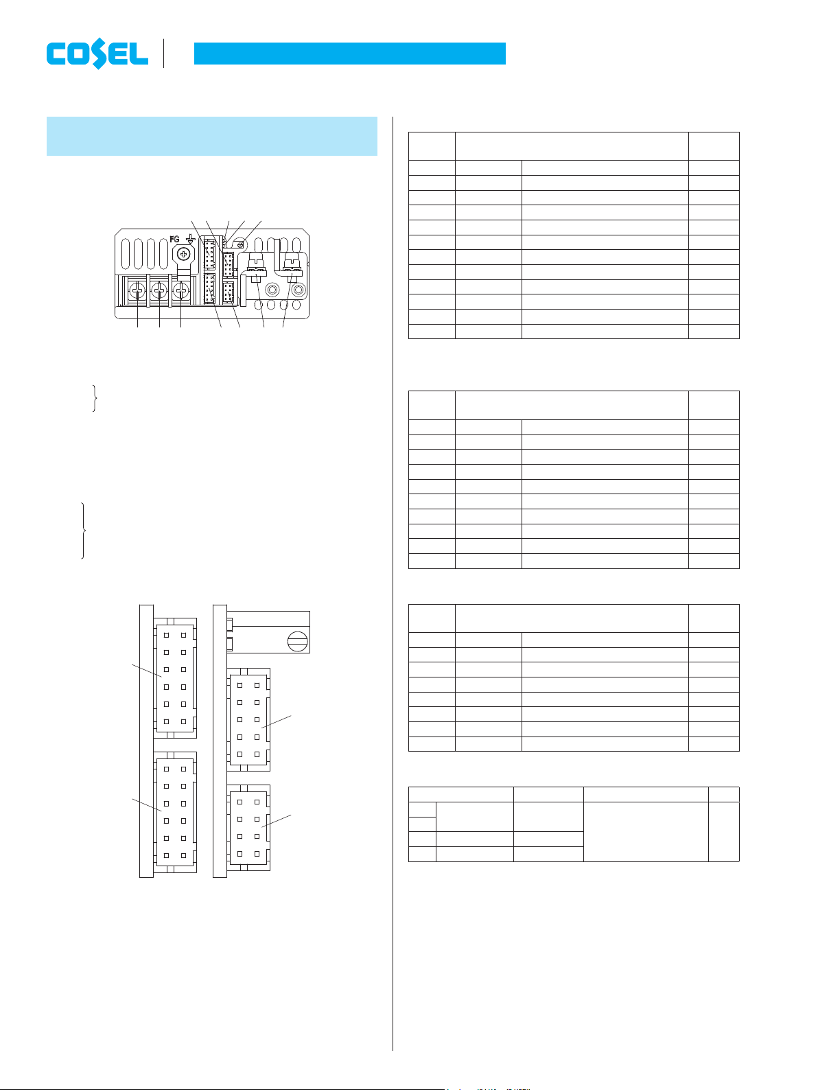
Table 1.1 Pin Conguration and Functions of CN1, CN2
Pin No. Function
1 +S +Remote sensing COM
2 N.C. No connection 3 N.C. No connection 4 -S -Remote sensing COM
5 VTRM Adjustment of output voltage COM
6 COM Common ground (for signal) COM
7 INFO Extended UART signal SGND
8 CM Current Monitor COM
9 MS Master Slave signal SGND
10 SGND Signal ground SGND
11 RC2 Remote ON/OFF RCG
12 RCG Remote ON/OFF ground RCG
Each terminal of CN1 and CN2 are connected inside the power supply.
*
Ground
level
AC (L)
1
AC (N) (M4)
2
Frame ground (M4)
3
4
+Output
5
LED for fault condition detection (ALARM)
6
LED for output voltage conrmation (DC_OK)
7
Output voltage adjustable potentiometer
8
CN1
9
CN2
9
CN3
0
CN4
9
Please refer to optional parts for the exclusive harness.
*
Input Terminals 85 - 264VAC 1f45 - 66Hz
-
Output
Connectors
12
CN1
12 11
10 9
12
CN2
1112
12
CN3
12
CN4
78
Table 1.2 Pin Conguration and Functions of CN3
Pin No. Function
1 AUX Auxiliary output AUXG
2 AUXG Auxiliary output ground AUXG
3 RC1 Remote ON/OFF AUXG
4 AUXG Auxiliary output ground AUXG
5 PG Alarm PGG
6 PGG Alarm ground PGG
7 ITRM Adjustment of output current COM
8 COM Common ground (for signal) COM
9 VTRM_EN Enable Vtrm COM
10 SLV_EN Enable Slave mode COM
Table 1.3 Pin Conguration and Functions of CN4
Pin No. Function
1 N.C. No connection -
2 SGND Signal ground SGND
3 N.C. No connection -
4 N.C. No connection -
5 ADDR0 Address bit 0 SGND
6 ADDR1 Address bit 1 SGND
7 ADDR2 Address bit 2 SGND
8 SGND Signal ground SGND
Table 1.4 Matching connectors and terminals
Connector Housing Terminal Mfr.
CN1
S12B-PHDSS PHDR-12VS
CN2
CN3
S10B-PHDSS PHDR-10VS
CN4
S8B-PHDSS PHDR-8VS
1 The manufacturer prepares only the ratchet hand.
*
Reel : SPHD-002T-P0.5
Loose : BPHD-001T-P0.5 *1
BPHD-002T-P0.5
Ground
level
Ground
level
1
*
J.S.T
Fig.1.1 Connector pin numbers
PCA-8
Page 4
Differential probe
AC-DC Power Supplies Enclosed Type
2
Wiring Input / Output Pin
2.1 Wiring input pin
(1) Fuse
For the PCA series, AC(L) and AC(N) both have a fuse built in.
¡
(2) Wire
Please use an electric wire that is both as thick and short as
¡
possible.
Noise could be improved if the wire is twisted. In addition, please
¡
be sure the input line and the output load are separated.
(3) Ground
When installing the power supply with your unit, ensure that the
¡
input FG terminal is connected to safety ground of the unit.
2.2 Wiring output pin
When wiring the load wire, select the wire in consideration of the
¡
heat generation so that the temperature of points A in Fig. 2.1 will
be below the specied temperature.
In the case of PCA600F-5-P2
Input condition: Vin=85 to 264VAC
When ambient temperature is 40ª or less, point A is 65ª or less
-
- When ambient temperature is 70ª, point A is 75ª or less
( The ambient temperature 40ª to 70ª should be not more than
the calculated value by linear interpolation)
Instruction Manual
The thermometry point is conductive. Please be careful of electric
¡
shocks.
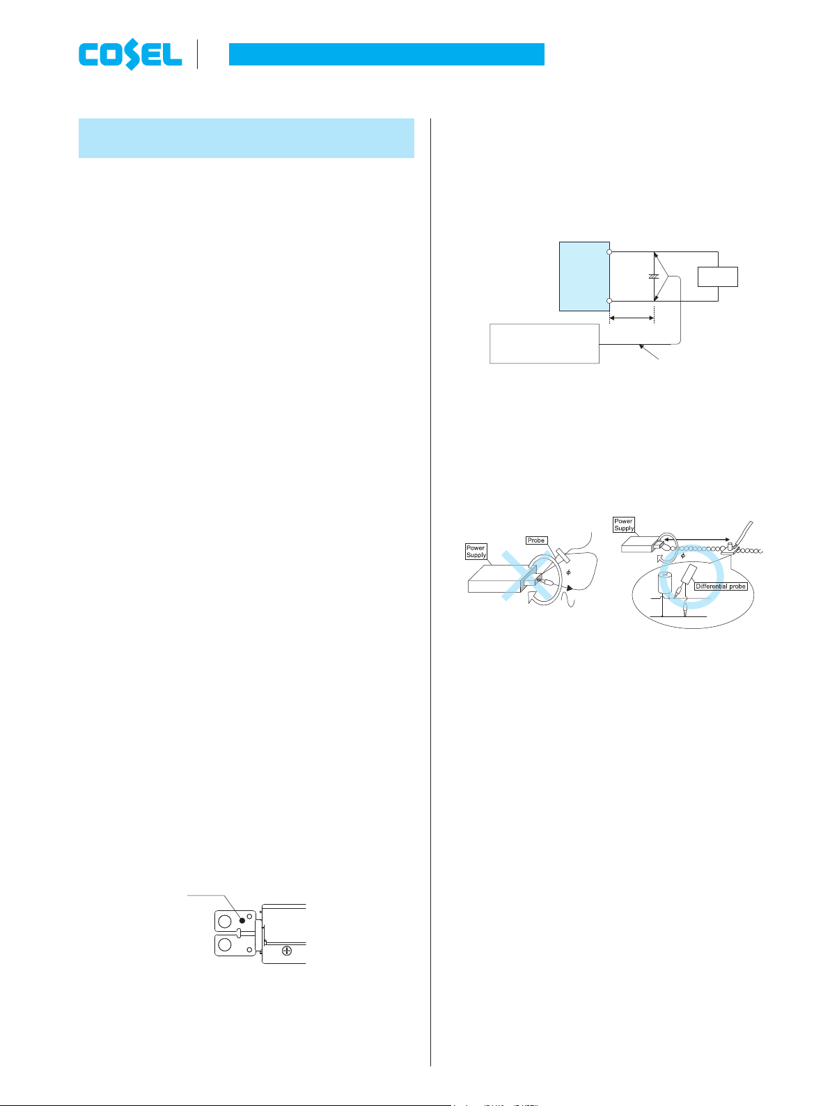
Output ripple noise may be influenced by measurement
¡
environment,measuring method Fig.2.2 is recommended.
Output ripple and ripple noise is the value measured by the
¡
method shown in Fig.2.2.
+Vout
1
C
+
-Vout
150mm
Osiloscope /
Ripple noise meter
Bw:20MHz
1 :
C
Aluminum electrolytic capacitor 22μF
Fig.2.2 Measuring method of Ripple and Ripple Noise
Remarks :
When GND cable of probe with ux of magnetic force from power
supply are crossing, ripple and ripple noise might not measure
correctly.
Please note the measuring environment.
Load
150mm
In the case of PCA600F-12,-15,-24 -P2
Input condition: Vin=85 to 170VAC
-
When ambient temperature is 40ª or less, point A is 65ª or less
- When ambient temperature is 70ª, point A is 75ª or less
( The ambient temperature 40ª to 70ª should be not more than
the calculated value by linear interpolation)
Input condition: Vin=170 to 264VAC
-
When ambient temperature is 50ª or less, point A is 80ª or less
- When ambient temperature is 70ª, point A is 75ª or less
( The ambient temperature 50ª to 70ª should be not more than
the calculated value by linear interpolation)
Point A
Fig. 2.1 Temperature measurement point
A thin electric wire could heat up and affect the power supply.
Please also use within the derating characteristics.
Bad example Good example
Fig.2.3. Example of measuring output ripple and ripple noise
2.3 Output side attaching externally condenser
Depending on the capacitance of the external capacitor, reso-
¡
nance may occur due to ESR, ESL, and wiring inductance, so
please be careful of ripple increase.
If the capacitance of the external capacitor is too large, the output
¡
voltage may not rise.
2.4 Connection to pulse load
When connecting a pulse load to the PCA series, connect a
¡
capacitor Co between +Vout and -Vout.
* If there is no external capacity when connected with pulse load,
output may be stopped by the internal protection circuit.
PCA-9
Page 5

AC-DC Power Supplies Enclosed Type
Instruction Manual
Output current
of power supply
+Vout
Co
-Vout
Fig. 2.4 Output side external capacitor connection method
Be careful that the output current of the power supply does not
¡
exceed the rated current.
Pulse
load
3 Functions
3.1 Input Voltage Range
Input voltage range of the power supplies is from 85VAC to
¡
264VAC.
In cases that conform with safety standard, input voltage range is
100-240VAC (50/60Hz).
If input value doesn’t fall within above range, a unit may not oper-
¡
ate in accordance with specications and/or start hunting or fail.
If you need to apply a square waveform input voltage, which is
commonly used in UPS and inverters, please contact us.
3.2 Inrush Current Limiting
An inrush current limiting circuit is built-in.
¡
If you need to use a switch on the input side, please select one
¡
that can withstand an input inrush current.
Relay technique is used in the inrush current limiting circuit. When
¡
you turn the power ON/OFF repeatedly within a short period of
time, please have enough intervals so that the inrush current limit-
ing circuit becomes operative.
When the switch of the input is turned on, the primary inrush cur-
¡
rent and secondary inrush current will be generated because the
relay technique is used for the inrush current limiting circuit.
3.3 Overcurrent Protection
An overcurrent protection circuit is built-in and activated at 105%
¡
or more of the rated current. A unit automatically recovers when a
fault condition is removed.
Please do not use a unit in short circuit and/or under an overcur-
rent condition.
Intermittent Operation Mode
¡
Intermittent operation for overcurrent protection is included in a
part of series. When the overcurrent protection circuit is activated
and the output voltage drops to a certain extent, the output be-
comes intermittent so that the average current will also decrease.
3.4 Overvoltage Protection
An overvoltage protection circuit is built in. When overvoltage
¡
protection operates, release it by shutting down input and re-input
after 10 seconds or setting the voltage of RC2 terminal to logic to
turn off output.
Note :
Please avoid applying a voltage exceeding the rated voltage to an
¡
output terminal. Doing so may cause power supply to malfunction
or fail. If this is unavoidable, for example, if you need to operate a
motor, etc., please install an external diode on the output terminal
to protect the unit.
3.5 Thermal Protection
A thermal protection circuit is built-in.
¡
The thermal protection circuit may be activated under following
conditions and shut down the output.
When a current and a temperature continue to exceed the val-
1
ues determined by the derating curve.
When a fan stops or air ow weakens by intake port or exhaust
2
port is blocked.
If the thermal protection circuit is activated, shut off the input volt-
age and eliminate all the overheating conditions. To recover the
output voltage, have enough time to cool down the unit before
turning on the input voltage again or setting the voltage of RC2
terminal to logic to turn off output.
3.6 External output voltage adjustment
To increase an output voltage, turn a built-in potentiometer clock-
¡
wise. To decrease the output voltage, turn it counterclockwise.
When the VTRM_EN and COM terminals on CN3 are shorted and
¡
the power supply starts up, the VTRM will be enabled. The output
voltage can be adjustable by external voltage applied between
VTRM and COM on CN1 or CN2. In this case, the output voltage
will be based on the calculation 1. However, even if 3.0V or more
is applied, the output voltage cannot be changed 120% or more.
Do not set the external applied voltage of the terminal to -0.3V or
less, and 5.0V or more.
In order to make it variable, it is necessary to apply voltage from
the outside.
The voltage between
Output voltage [V] = XRated output voltage [V]
When the VTRM is enabled, the potentiometer for the output volt-
¡
age adjustment will be disabled.
Switch the VTRM terminal, it is necessary to turn on the power
¡
again.
When using the external voltage control function, when the VTRM
¡
terminal becomes open, the output voltage drops to around 0V.
When the output voltage is adjusted to less than the adjustment
¡
voltage range, the output ripple voltage might increase.
VTRM and COM [V]
2.5 [V]
---
1
PCA-10
Page 6

AUXG
SW
AC-DC Power Supplies Enclosed Type
3.7
Constant current set value external variables
The output current for the constant current can be adjustable by
¡
the external voltage applied to between ITRM and COM on CN3.
Output current will be based on the calculation 2.
Do not set the external applied voltage of the terminal to -0.3 V or
less, and 5.0 V or more.
When the output current is adjusted to around 0A, the unit might
be unstable.
Load factor of 100% or higher should be avoided since it will be
used outside the specications.
To change it, you can connect an external resistor or apply voltage
from the outside.
The voltage between
Output current [A] = XRated output current [A]
ITRM and COM [V]
2.5 [V]
---
2
Instruction Manual
AUX
2.2kΩ
12V
150Ω
(Example: V1=5V, R1=620Ω)
RC1
V1
RC2
R1
RCG
AUXG
(a) (b)
SW
12V
12V
2.2kΩ
150Ω
2.2kΩ
150Ω
AUX
RC1
RC2
RCG
AUXG
AUX
RC1
RC2
SW
RCG
3.8 Remote ON/OFF
These models have a remote ON/OFF function.
¡
You can operate the remote ON/OFF function by sending signals
¡
to CN1 or CN2. Specications are shown in Table 3.1 and connec-
tion examples are shown in Fig. 3.1.
Remote ON/OFF circuit (RC2, RCG) is isolated from input, output,
¡
FG, AUX and various function terminals.
Please note the followings when using the remote ON/OFF func-
¡
tion.
The output stops when the current is drawn in RC2.
1
The current owing into RC 2 is 5mA typ (12mA max).
2
The PG signal turns to “High” when the output voltage is turned
3
off with remote ON/OFF.
AUX can be used even if the output is off with remote control.
4
Even if the output is turned off by remote control, the built-in
5
fans will continue to operate.
Since the contents of this manual are values when using one
6
unit, pay attention to the necessary current / voltage value when
operating in parallel or in multiple units.
If voltage / current other than those shown in Table 3.1 is ap-
7
plied between RC2 and RCG, the output voltage may not be
output correctly.
Table 3.1 Specications of remote ON/OFF
Connection method Fig. 3.1 (a) Fig. 3.1 (b) Fig. 3.1 (c)
Output ONSW open
SW Logic
Output
OFF
Base pin RCG AUXG RCG, AUXG
(0.1mA max)
SW close
(3mA min)
SW open
(0.1mA max)
SW close
(3mA min)
SW close
(0.5V max)
SW open
(0.1mA max)
(c)
Fig. 3.1 Examples of connecting remote ON/OFF circuit
3.9 Remote sensing
These models have a built-in remote sensing function.
¡
When remote sensing is not used, +S and -S can be left open.
Please see Fig. 3.2 if you do not use the remote sensing function.
¡
Please see Fig. 3.3 if you use the remote sensing function.
When you use the remote sensing function, please wire from +S
¡
and -S on CN1 or CN2. Harnesses are available for your pur-
chase. For details, refer to the item of option parts.
When you use the remote sensing, please note the followings.
¡
Wire carefully. When a connection of a load line becomes loose
1
(due to such factors as loose screw), the load current ows to
the sensing line and internal circuits of the power supply may be
damaged.
Use a sufciently thick wire to connect between the power sup-
2
ply and the load and keep the line drop at 0.3V or below.
Use a twisted pair wire or a shielded wire as the sensing line.
3
Do not draw the output current from +S or -S.
4
When the remote sensing function is used, the output voltage
5
of the power supply may show an oscillating waveform or the
output voltage may dramatically uctuate because of an imped-
ance of wiring and load conditions.
Please check and evaluate carefully before using the remote
sensing function.
If the output voltage becomes unstable, we suggest you to try
the followings.
Connect C1, R1 and R2.
-
If oscillation occurs because the sensing line is long, adjust with
6
R1.
Please contact us for details.
PCA-11
Page 7

Wire as close as possible
AC-DC Power Supplies Enclosed Type
Instruction Manual
OPEN
CN1
+S
or CN2
Fig. 3.2 When not using remote sensing function
Fig. 3.3 When using remote sensing function
CN1
or CN2
+V
-S
1
+S
C
-S
C
R2
-V
+V
-V
Load
R1
Load
1
3.10 Signal Output (LED / Alarm)
Functions of LED indicators and Output of Alarm are shown below.
¡
LED indicators and Output of Alarm are signals to check the pres-
ence/absence of voltage at the output terminal of a power supply
and to detect fault conditions.
The timing of signals might vary depending on input and load
conditions. Please evaluate thoroughly.
Table 3.2 LED indicator and Condition of Power supply
LED indicator
Blue Orange
OFF OFF
ON OFF Normal condition ON
OFF ON Fault condition OFF
Condition of Power supply Output
Turned off with remote ON/OFF,
or decreased output voltage
OFF or
Decreased
PG
100kW0.1mF
PGG
Fig.3.4 Internal circuit of PG
Please note the followings when you use the alarms (PG signal).
¡
1 The PG signal turns to “High” when the output voltage is turned
off with remote ON/OFF.
2 When the output voltage drops to 40% or less of the rated out-
put voltage, the PG signal is “High”.
Circuit of the alarm is isolated from input, output, FG, AUX and
¡
various function terminals.
3.11 Communication function
The power supply provides an “Extended UART”(INFO terminal)
¡
digital interface that enables the user to congure many aspects
of the device operation as well as monitor the input and output pa-
rameters.
Please contact us for details.
Extended UART is a communication protocol that enables single-
¡
wire, bidirectional, insulated, and multiple communication of
UART, which is a general-purpose communication standard.
For details, please refer to the PCA Series Extended UART
Manual.
Communication function terminal is isolated from input, output,
¡
FG, AUX and various function terminals.
Table 3.3 Explanation of alarm
Alarm Output of Alarm
The PG signals is “Low” when
the power supply operates correctly. The signal turns to “High”
PG
when the power supply stops.
PCA-12
Open collector method
Good : Low
(0.5V max at 5mA)
Bad : High
50V 5mA max
Page 8

AC-DC Power Supplies Enclosed Type
4
Series/Parallel Operation
Instruction Manual
and input is restarted after 10 seconds or setting the voltage of
RC2 terminal to logic to turn off output.
4.1 Series Operation
Wiring method with series operation is shown in Fig.4.1.
¡
The MS and SGND must be connected with each other.
Please use option part H-PA-14 for connecting between MS and
SGND.
Please decide one power supply (master power supply) to be op-
erated on the volume and short circuit between SLV_EN and COM
of the other power supply (slave power supply).
To short-circuit between SLV_EN and COM, please use option
part H-SN-53.
Use the Master when changing the output voltage.
If one of the units operated in series stops or fails, all the power
supplies are stopped by signal information of the MS terminal.
To start / stop use the remote ON/OFF control function. Connect
RC 2 and RCG of all power supplies to be operated in series and
start / stop all at the same time.
It is necessary to turn the power supply on again to switch the
mode of Master/slave.
When using in series operation, use products of the same model
name.
Implement H-PA-14
No.3 (Slave)
Implement H-SN-53
4.2 Parallel Operation/Master-slave Operation
Wiring method with series operation is shown in Fig.4.2.
¡
The MS and SGND must be connected with each other.
Please use option part H-PA-14 for connecting between MS and
SGND.
Please decide one power supply (master power supply) to be op-
erated on the volume and short circuit between SLV_EN and COM
of the other power supply (slave power supply).
To short-circuit between SLV_EN and COM, please use option
part H-SN-53.
Use the Master to change the output voltage.
If one of the units operating in parallel stops or fails, all the power
supplies are stopped by signal information of the MS terminal.
To start / stop use the remote ON/OFF control function. Connect
RC 2 and RCG of all power supplies to be operated in parallel and
start / stop all at the same time.
It is necessary to turn the power supply on again to switch the
mode of the Master/slave.
When using in parallel operation, use products of the same model
name.
As variance of output current drew from each power supply is
maximum 10%, the total output current must not exceed the value
determined by the following equation.
(Output current at parallel operation)
= (the rated current per unit) × (number of unit) × 0.9
No.2 (Slave)
Load
No.1 (Master)
Fig.4.1 Connection method in series
Notes on series operation
*
(1) Constant current set value external variable function cannot be
used.
(2) When the overcurrent condition occurs, the latch stop operation
is performed.
In order to release the latch stop operation, input is shut down
When the number of units in parallel operation increases, the in-
¡
put current also increases. Please design input circuitry (including
circuit pattern, wiring and current capacity for equipment) carefully.
Please make sure that the wiring impedance of a load from each
¡
power supply becomes even. Otherwise, the output current bal-
ance circuit may become inoperative.
The maximum number of units you can use in parallel operation is
¡
3.
PCA-13
Page 9

No.3 (Slave)
No.2 (Slave)
AC-DC Power Supplies Enclosed Type
Implement H-PA-14
Implement H-SN-53
5 Assembling and
Installation Method
5.1 Installation Method
To keep enough isolation between screws and internal compo-
¡
nents, the length of mounting screws should not exceed Fig. 5.1.
Chassis of
customer system
Instruction Manual
1.5mm
Chassis of
PCA600F
No.1 (Master)
Fig.4.2 Connection method in parallel
Notes on parallel operation
*
(1) It is recommended to use the output current during parallel op-
eration at 10% or more of the total of the rated output current.
If a current exceeding the rated current is instantaneously taken
out where the total of the rated output currents is 10% or less,
the output may decrease or stop.
(2) Constant current set value external variable function cannot be
used.
(3) When the overcurrent condition occurs, the latch stop operation
is performed.
In order to release the latch stop operation, input is shut down
and input is restarted after 10 seconds or setting the voltage of
RC2 terminal to logic to turn off output.
Load
Screw M4
6mm max
Fig.5.1 Mounting screw
Please do not block built-in fans and ventilation holes.
¡
When the power supply is mounted by screws, please consider its
weight and set it in place. (Please see Fig. 5.2)
If you use a power supply in a dusty environment, it can give a
¡
cause for a failure. Please consider taking such countermeasures
as installing an air lter near the suction area of the system to pre-
vent a failure.
(a)
PCA-14
(c)(b)
In case of (c), fix it
from both directions.
Fig.5.2 Installation method
Page 10

AC-DC Power Supplies Enclosed Type
Instruction Manual
5.2 Derating
Ambient Temperature Derating Curve
¡
Fig. 5.3 shows the derating characteristics due to the operating
ambient temperature of the power supply (the temperature of the
air drawn in for cooling).
Specications for ripple and ripple noise changes in the shaded
*
area.
100
Vin=85 to 264VAC *
50
Load factor [%]
0
100
50
Load factor [%]
0
Ambient temperature [C]
(a) PCA600F-5-P2
1Vin=85 to 170VAC *
2Vin=170 to 264VAC
Ambient temperature [C]
(b) PCA600F-12,-15,-24 -P2
1
7040 60-20 200-10 10 30 50
80
2
7040 60-20 200-10 10 30 50
80
5.3 Life expectancy and Warranty
Life expectancy
¡
Life expectancy is as follows.
Table.5.1 Life expectancy
Mount
All mounting
direction
Life expectancy (R(t)=90%) of fan depends on use conditions as
¡
Average ambient
temperature (yearly)
Ta [ 35
C
Ta = 40
C
Ta = 50
C
shown in Fig.5.5.
100,000
Life expectancy of fan [H]
10,000
Ambient temperature [C]
(a) PCA600F-5-P2
100,000
Life expectancy
0%
50% 50%<Io[100%
[Io[
8 years 6 years
7 years 5 years
6 years 4 years
Io=20% (
Io=50% (
Io=100% (
Io=100% (
Io=20% (
Io=50% (
Io=100% (
Io=100% (
Vin=85 to 264VAC
Vin=85 to 264VAC
Vin=85 to 170VAC
Vin=170 to 264VAC
Vin=85 to 264VAC
Vin=85 to 264VAC
Vin=85 to 170VAC
Vin=170 to 264VAC
)
)
)
)
)
)
)
)
807040 6030 50
Fig.5.3 Ambient temperature derating curve
*
Input Voltage Derating Curve
¡
With derating due to input voltage
Input voltage derating curve is shown in Fig.5.4.
100
90
Load [%]
85 90
AC input voltage [VAC]
Fig.5.4 Derating curve depends on AC input voltage
Life expectancy of fan [H]
10,000
Ambient temperature [C]
(b) PCA600F-12,-15,-24 -P2
807040 6030 50
Fig.5.5 Life expectancy of fan
Warranty term
¡
Warranty is as follows and shall be 5 years maximum.
Warranty does not apply if used outside of derating specications.
Table.5.2 Warranty term
Mount
All mounting
direction
Average ambient
temperature (yearly)
Ta [ 35
C
Ta = 40
C
Ta = 50
C
Free warranty period
0%
50% 50%<Io[100%
[Io[
5 years 5 years
5 years 5 years
5 years 4 years
PCA-15
Page 11

[V]
AC-DC Power Supplies Enclosed Type
6 Others
6.1 Output Current Monitor
You can monitor an output current by measuring a voltage be-
¡
tween the terminal CM and COM.
Fig.6.1 shows the relationship between the voltage of the terminal
¡
CM and the output current.
The output current shown in Fig.6.1 should be used only as a
guide.
3
Instruction Manual
When you connect a DC-DC converter, a current a few times
higher than normal current may ow at start-up. Please check the
current.
Output voltage can be varied (5V to 12V).
¡
Please contact us for more details
The maximum capacitance of the extermal capacitor is 22µF.
¡
6.4 Variable Speed Fan
The power supply has built-in variable speed cooling fan. The fan
¡
speed is a function of load and ambient temperature.
6.5 Medical Isolation Grade
PCA series t 2MOPP
¡
2MOPP
Voltage of
CM terminal
0
Load factor
Load factor :
Fig.6.1 Load current conversion graph
Please note the followings when measuring the voltage of the ter-
¡
minal CM.
Wire carefully to avoid malfunction caused by noise.
-
Use a measuring instrument whose input impedance is 500kW
-
or more.
Do not short-circuit between CM terminal and COM terminal.
-
Doing so could cause a failure.
100
Output current
Rated current
6.2 Isolation
When you run a Hi-Pot test as receiving inspection, gradually in-
¡
crease the voltage to start. When you shut down, decrease the
voltage gradually by using a dial. Please avoid a Hi-Pot tester
with a timer because, when the timer is turned ON or OFF, it may
generate a voltage a few times higher than the applied voltage.
When you test a unit for isolation between the input and output,
¡
input and the terminal FG or between the output and the terminal
FG, short-circuit between the output and all function terminals.
[%]
primary
1MOPP
Fig.6.2 Medical Isolation Grade
secondary
Safety GND
6.3 Auxiliary Power (AUX)
Auxiliary power(AUX : 12V0.1A) is possible for remote ON/OFF
¡
and its attached circuit from CN3.
AUX circuit(AUX,AUXG) is isolated from input ,output,FG,and
¡
function terminals other than RC1.
Please do not take out the current which exceeds 0.1A from AUX
¡
to avoid the breakdown of the power supply or malfunction.
PCA-16
Page 12

7 Options
AC-DC Power Supplies Enclosed Type
Instruction Manual
7.1 Outline of Options
Please inquire us for details of specications and delivery timing.
*
-TP2
¿
Option -T units have a terminal block in stead of an output bus bar.
¡
For PCA600F, this option is available in -12V, -15V and -24V types.
¡
When wiring the load wire, select the wire in consideration of the
¡
heat generation so that the temperature of points A in Fig. 7.2 will
be below the specied temperature.
Please note that if the wire is thin, the wiring heats up, heat is
transferred to the inside of the power supply, and the power sup-
ply may break down.
Please use within the item number 5.2 derating characteristics.
Input condition: Vin=85 to 170VAC
When ambient temperature is 40ª or less, point B is 70ª or less
-
- When ambient temperature is 70ª, point B is 75ª or less
( The ambient temperature 40ª to 70ª should be not more than
the calculated value by linear interpolation)
Input condition: Vin=170 to 264VAC
When ambient temperature is 50ª or less, point B is 85ª or less
-
- When ambient temperature is 70ª, point B is 75ª or less
( The ambient temperature 50ª to 70ª should be not more than
the calculated value by linear interpolation)
Point B
Fig.7.2 Temperature measurement point
Please pay attention to electric shock and leakage during mea-
surement. Temperature formulation place is conductive part.
1 2 3 4 5
Fig.7.1 TP2 specication example (PCA600F)
AC (L)
1
2
3
4
5
Input Terminals 85 - 264VAC 1f45 - 66Hz
AC (N) (M4)
Frame ground (M4)
-
Output (M5)
+Output (M5)
PCA-17
 Loading...