


Basic Characteristics Data
Basic Characteristics Data
Switching
Model Circuit method
Active filter 47
FETA7000ST
Phase-shift Full-
bridge converter
* The value of input current is at ACIN 400V and rated load.
frequency
[kHz]
94
Input
current
[A]
Rated
input fuse
Inrush
current
protection
circuit
PCB/Pattern
Material
Single
sided
Double
sided
Series/Parallel
operation availability
Series
operation
operation
12.0 250V 30A Relay FR-4 Ye s Ye s Ye s
Parallel
FETA-6

AC-DC Power Supplies Enclosed Type
Instruction Manual
1 Terminal Blocks
2 Functions
2.1 Input Voltage Range
2.2 Inrush Current Limiting
2.3 Overcurrent Protection
2.4 Overvoltage Protection
2.5 Thermal Protection
2.6 Output Voltage Adjustment Range
2.7 Output Ripple and Ripple Noise
2.8 Remote ON/OFF
2.9 Isolation
2.10 Signal Output (LED / Warning / Alarm)
2.11 Sequence Diagram
3 Series/Parallel Operation
3.1 Series Operation
3.2 Parallel Operation/Master-slave Operation
3.3 N+1 Parallel Redundancy Operation
FETA-8
FETA-8
FETA-8
FETA-8
FETA-9
FETA-9
FETA-9
FETA-9
FETA-9
FETA-10
FETA-10
FETA-10
FETA-11
FETA-12
FETA-12
FETA-12
FETA-12
Assembling and Installation Method
4
4.1 Installation Method
4.2 Derating
4.3 Conditions of the safety approval
4.4 Expected Life and Warranty
5 Others
5.1 Output Current Monitor
5.2 Auxiliary Power (AUX)
5.3 Output Capacitive Load Considerations
5.4 External Component (EMI/EMC Filter)
5.5 Ground
5.6 Variable Speed Fan
FETA-13
FETA-13
FETA-14
FETA-14
FETA-14
FETA-15
FETA-15
FETA-15
FETA-15
FETA-15
FETA-15
FETA-15
FETA-7
AC-DC Power Supplies Enclosed Type
Instruction Manual
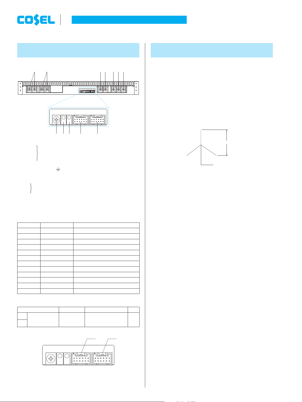
1 Terminal Blocks
7
90å∫
AC (L3)
1
AC (L2)
2
AC (L1)
3
AC (N)
4
Frame ground (M5
5
+Output
6
-
Output
7
CN2
8
CN1
9
LED for output voltage conrmation (DC_OK)
0
LED for fault condition detection (ALARM)
å
Output voltage adjustable potentiometer
∫
Pin No. Pin Name Function
Table 1.2 Matching connectors and terminals on CN1, CN2
CN1
CN2
Input Terminals AC300-480V three phase four wire 47 - 63Hz
(M5)
)
Connectors
Table 1.1 Pin Conguration and Functions of CN1, CN2
1 AUXG Auxiliary power output (GND)
2 AUX Auxiliary power output
3 WRNG Warning signal (GND)
4 WRN Warning signal
5 PGG Alarm signal (GND)
6 PG Alarm signal
7 RCG Remote ON/OFF (GND)
8 RC Remote ON/OFF
9 COM Signal ground
10 TRM Adjustment of output voltage
11 VB Voltage Balance
12 CB Current Balance
Connector Housing Terminal Mfr.
S12B-PUDSS-1 PUDP-12V-S
8
Reel : SPUD-001T-P0.5
or SPUD-002T-P0.5
2 Functions
123456
J.S.T
2.1 Input Voltage Range
The input voltage range is AC300-480V (three phase four wire).
¡
For the safety standard test, the input voltage range is AC346-
¡
415V (three phase four wire, 50/60Hz).
The current owing through the neutral line (N phase) increases
¡
when the AC input voltage is over AC456V three phase four wire
(18Amax). This does not affect product quality. Please select a
suitable wire gauge for the neutral line.
L1
AC300 - 480V
L2 L3
N
Three phase four wire system
Three phase three wire input voltage is not supported.
¡
The neutral line must be connected.
If the input voltage is not from three phase four wire connection or
out of the specied range, the unit will not operate properly and/or
may be damaged. If you need to apply a square wave form input
voltage, which is commonly used in UPS and inverters, please
contact us.
2.2 Inrush Current Limiting
An inrush current limiting circuit is built-in.
¡
If you need to use a switch on the input side, please select one
¡
that can withstand an input inrush current.
Relay technique is used in the inrush current limiting circuit. When
¡
you turn the power ON/OFF repeatedly within a short period of
time, please have enough intervals so that the inrush current limit-
ing circuit becomes operative.
When the switch of the input is turned on, the primary inrush cur-
¡
rent and secondary inrush current will be generated because the
relay technique is used for the inrush current limiting circuit.
FETA-8
11
12
1
2
1
2
Fig.1.1 Connector pin numbers
CN2CN1
11
12
 Loading...