

COSDEP STQ14, ST18, MTQ28, MTC28, STQ18 User And Maintenance Manual
...
1
USER’S AND MAINTENANCE HANDBOOK FOR
ECO-PELLET STOVES
STQ14 square covering
ST18 Round covering-STQ18 Square covering-STC18 Fantasy
MT28 Round covering-MTQ28 Square covering-MTC28 Fantasy
SERIAL NUMBER
COSDEP di Vighesso Onorio S.a.s.
Via Copernico, 25, 36034 Malo (VI) ITALY
Tel. (0039) 0445 605255 / 602414 Fax (0039) 0445 602464
Internet: www.cosdep.com e-mail: info@cosdep.com
ST-MT
STQ-MTQ
STC-MTC

2
CONTENTS
1. INTRODUCTION..………………...………………………………………………............. 3
1.1 General precautions
1.2 Compliance with standards
1.3 Rules and instructions
1.4 Declaration of conformity
2. GENERAL DESCRIPTION…………………………………..………………................ 5
2.1 Operating principle
2.2 Pellets and qualities available on the market
2.3 The pellet tank
3. INSTALLATION AND IGNITION ……………………………………………............ 6
3.1 Choosing the correct stove size
3.2 Unpacking and positioning the stove
3.3 The location of the stove and connection to a chimney
3.4 Ignition, starting up
3.5 Diagram explaining display sequences
3.6 Switching off/extinguishing the stove
4. HOW TO PROGRAMME THE STOVE ……..………..……………………............ 10
4.1 Description of control panel
4.2 Selecting function menus
1. The DATE and TIME menu…………………………………………………………………………….. 11
2. The RECIPE SELECTION………………………………………………………………………….……… 12
3. The OPERATING MODE menu……………………………………………………………………….. 13
4. the WEEKLY PROGRAMME menu…………………………………………………………………… 13
5. The TIMER COUNTDOWN menu………………………………………………………………….. . 14
6. The SELECT LANGUAGE menu…………………………………………………………………….. . 15
7. The BUZZER menu………………………………………………………………………………………… 15
8. The THERMOSTAT MODE menu…………………………………………………………………… . 15
9. The IR REMOTE CONTROL (optional) menu…………………………………………………. 16
10. The ASSISTANCE menu………………………………………………………………………………. 16
11. The DEBUG menu………………………………………………………………………………………… 17
12. The SERVICE menu……………………………………………………………………………………….. 18
5. FORMULATION PARAMETERS TO THE TYPE OF PELLET..........………….. 19
6. CLEANING, MAINTENANCE AND REPAIRS....................…………………… 20
6.1 Every day
6.2 Once a week
6.3 Once a month or whenever there are ignition problems
6.4 At the end of the winter
6.5 Changing the (optional) remote control battery
6.6 Repairs
7. TECHNICAL SPECS. AND DIAGRAM SHOWING OPERATION..........…… 24
8. ELECTRICAL DIAGRAM………………………………………………………................ 26
9. GENERAL THERMOSTAT WITH MANUAL RESET.............................. 27
10. ELECTRIC BOX…………………………………………………………………............. 27
11. ERROR MESSAGES………………………………………………………….............. 28
12. DISPOSING OF THE STOVE…………………………………………….............. 28
13. GUARANTEE........................................................................... 29

3
1. INTRODUCTION
1.1 GENERAL PRECAUTIONS
This user’s and installation handbook is an
indispensable, integral part of the product;
it should be used and kept with care where
it can be read by all users.
Read all the instructions in the handbook
before starting to install the product.
The apparatus should be utilised only and
exclusively for the purposes for which it
was intended. Any other improper use is to
be considered dangerous for the user and
will invalidate the guarantee.
Do not place any object whatsoever on the
stove.
Do not use inflammable substances to
ignite the stove.
Make sure there are no inflammable
objects, furniture or household linen in the
immediate vicinity of the stove. Respect
the safety distances given in the
handbook.
Keep children away from the stove when it
is in operation.
Do not obstruct the intake and ventilation
grilles of the stove in any way whatsoever.
Installation, maintenance and any
necessary repairs should be carried out by
skilled personnel, using only and
exclusively original spare parts, otherwise
the guarantee will be invalidated.
The manufacturer declines all liability for
incorrect installation or maintenance that
may cause damage people or objects
When carrying out cleaning and
maintenance make sure that the appliance
is switched off, cool and disconnected from
the power supply.
The product should be situated on
premises with fire-fighting devices and
with adequate air change.
If the appliance is sold to third parties
make sure that the new user is provided
with this handbook.
The manufacturer has the copyright on this handbook. The instructions herein may not be
duplicated or communicated to third parties and may not be used for competitive purposes without
due authorisation.
1.2 COMPLIANCE WITH STANDARDS
The ST16 and MT24 pellet stoves comply with the following standards:
The electronics comply with electromagnetic compatibility directive 89/336/CEE and subsequent
amendments.
List of tests required for Residential, Commercial and Light Industry premises
General Standard CEI EN 50081-1
(Emissions for Residential, Commercial and Light Industry premises)
Tests for standard of reference
RADIATED electromagnetic EMISSIONS EN 55022
CONDUCTED electromagnetic EMISSIONS (30 MHz, 300 MHz) EN 55014
HARMONIC current EMISSIONS EN 61000-3-2
Voltage fluctuation and FLICKER EMISSIONS EN 61000-3-3
CONDUCTED electromagnetic EMISSIONS (150 kHz, 30 MHz) EN 55014

4
General Standard CEI EN 55104
Immunity of Household Appliances, Electric Tools and Similar Apparatus)
Tests for standard of reference
Electrostatic discharge IMMUNITY EN61000-4-2
Radiated, radio frequency electromagnetic field IMMUNITY EN 61000-4-3
Electrical fast transient/ BURST IMMUNITY EN 61000-4-4
SURGE IMMUNITY EN 61000-4-5
Conducted disturbances induced by radio frequency fields IMMUNITY EN 61000-4-6
Voltage dips, short interruptions and voltage variations IMMUNITY EN 61000- 4-1
All electrical and electronic parts comply with the new ROS standards.
1.3 RULES AND INSTRUCTIONS
RECOMMENDATIONS:
In order to use the appliance correctly it is necessary to carefully read the all instructions
contained in this handbook.
Do not use the appliance or carry out any maintenance until you have read this handbook.
Should the appliance be modified or tampered with, the user shall be deemed liable.
IMPORTANT: The appliance must be connected to a (PE) ground installation (low voltage directives
73/23 CEE, 93/98 CEE).
1.4 DECLARATION OF CONFORMITY
DECLARATION OF CONFORMITY
In accordance with Low Voltage Directive 73/23 CEE, Electromagnetic Compatibility Directive
89/336 CEE, Machinery Directive 98/37 CEE, integrated with CE mark according to Directive 93/68
CEE.
Other standards of reference: STANDARD EN 60 335-1:94 + A11:95
+A12:96+A1:96+A13:98+A14:98+A2:00+A15:00+A16:01
DEVIATION PROCEDURES: EN 50165:1997+A1:01
The company COSDEP di Vighesso Onorio sas, registered office Via Copernico No. 25, MALO, Italy
hereby declares that the products
PELLET STOVES mods. STQ14-ST18-STQ18-SCT18 and MT28-MTQ28-MTC28
have been designed and built in conformity with the aforementioned EU Directives and with the
corresponding assimilated Italian laws, in order to apply the CE mark.
Malo, 1st July 2006 COSDEP di Vighesso Onorio sas
Via Copernico,25
36034 MALO – VI- ITALY
Tel. (0039) 0445/605255 – 0445/602414
Fax (0039) 0445/602464

5
2. GENERAL DESCRIPTION
2.1 OPERATING PRINCIPLE
The STQ14-ST18-STQ18-STC18 and MT28-MTQ28-MTC28 stoves have been especially designed to
satisfy requirements for a practical heating appliance. They have a fan to circulate the heat
produced by the burning pellets and are designed for clean, extremely efficient combustion.
Nevertheless, there is a range of pellets on the market and the different qualities may affect
combustion and produce larger quantities of ash.
Besides the notice "WAIT" allows to reduce the consumption of pellet because the stove switches off
itself when the temperature environment overcomes of 2 degrees the temperature setting and
automatically the stove switches on again itself when the temperature environment goes down of 1
degree respect the setting one.
P.S. During the notice "WAIT" it is possible to switch OFF the stove pressing the OFF key
2.2 PELLETS AND QUALITIES AVAILABLE ON THE MARKET
Pellets are a by-product of wood "dust”. The resulting sawdust is pressed to form cylinders with a
diameter of 6 mm and a maximum length of 30 mm. They have a maximum moisture content of
10% and a thermal value of 4.9 kW/kg. The best pellets on the market are a blend of beech and
pine dust.
Standards DIN 51731 and ÖNORM M 7135 define pellet quality:
Length: approx. 10 - 30 mm
Diameter: approx. 6 mm
Actual weight: approx. 650 kg/m³
Thermal value: approx. 4.9 kW/Kg
Residual moisture: approx. 6 – 12%
Ash: < 1.5%
Specific weight: > 1.0 kg/dm³
It is also possible to make a visible assessment of pellet quality:
Good quality: shiny, smooth, constant length, very little dust.
Bad quality: horizontal and cross-wise cracks, a lot of dust, varying length.
A simple test for finding a good pellet is to measure its specific weight by putting a few grains into a
glassful of water:
Good quality: the pellet immediately falls to the bottom
Poor quality: the pellet floats
Using other material than that described above as fuel will have an adverse affect on stove
operation and will invalidate the guarantee.
2.3 THE PELLET TANK
The tank holding the reserve of pellets is at the top of the stove. To get at the tank it is necessary
to open the lid on the top. The maximum capacity of the tank depends on the model:
STQ14 - approx. 10 kg
ST18-STQ18-STC18 - approx. 15 kg
MT24-MTQ24-MTC28 - approx. 30 kg

6
3. INSTALLATION AND IGNITION
3.1 CHOOSING THE CORRECT STOVE SIZE
When calculating the stove size it is necessary to consider the volume of the room where it is to be
installed, the hourly requirement of calories to heat the room and the hourly consumption of pellets
(kg).
The following calculations show how to choose the correct stove size:
Volume of room = Length x Width x Height
Kcal/h required for room = 40 approx. (depending on how the building is insulated)
1 kg top quality pellet = 4.9 kW = 4214 kcal/kg
example: room measuring 8m x 5m x 2.7m = 108 m³
108 m³ x 40 Kcal/h = 4320 kcal/h total requirement for the room
Pellet consumption per hour:
STQ14 1,4 kg/h at maximum speed
ST18-STQ18-STC18 1.8 kg/h at maximum speed
MT28-MTQ28-MTC28 2.8 kg/h at maximum speed
1,4 kg/h x 4214 Kcal/kg = 5899 Kcal/h output
1.8 Kg/h x 4214 Kcal/kg = 7585 kcal/h output
2.8 kg/h x 4214 Kcal/kg = 11799 kcal/h output
For the room above, we recommend installing a ST 16 stove.
3.2 UNPACKING AND POSITIONING THE STOVE
The packed stove has already been assembled and is ready for installation. We recommend keeping
it upright when you move it, using appropriate equipment and taking special care with the glass
door. After positioning the stove in the chosen place unpack it, taking care to remove all packing,
which could harm its operation. Align the feet so that the stove is perfectly level and install the
heatproof surface underneath to protect the floor. Using the screws supplied, install the control
panel on top of the stove. To check that the white plastic spar of the sensor is straight.
When disposing of the packing, follow the regulations in the country where the stove is being
installed.
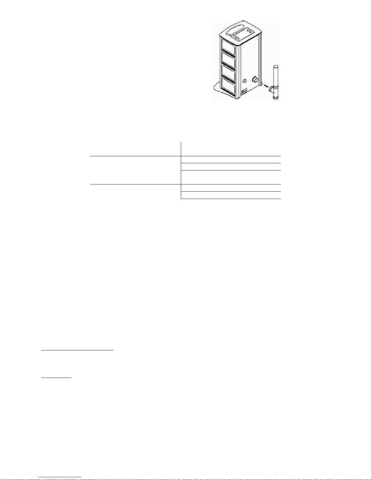
3.3 THE LOCATION OF THE STOVE AND CONNECTION TO A CHIMNEY
The stove should be connected to an 80 mm diameter exhaust flue with a 90° connection.
If the exhaust flue is connected to a chimney, the latter should be inspected and cleaned of all soot
residues and its diameter should be at least 130 mm.
The pipe connectors should be sealed by gaskets or can be sealed with high temperature silicone.
You should make sure that your chimney flue complies with current UNI standards.
7
It is very important to use only and
exclusively material that is suitable for this
type of installation therefore it must be
resistant to high temperatures.
Installation should be carried out by
specialised, skilled personnel.
If the floor under the stove is made of inflammable material, you must insert a heat-resistant
surface between the floor and the stove and comply with minimum safety distances.
MINIMUM SAFETY DISTANCES
From non-inflammable
objects:
Behind stove > 100 mm
At side of stove > 100 mm
In front of stove > 400 mm
From inflammable objects:
Behind stove > 200 mm
At side of stove > 200 mm
In front of stove > 800 mm
The exhaust flue must be installed in compliance with a number of standards:
UNI 7129/92 standards.
Among the countless assumptions, it is necessary to bear the following in mind:
use only products that are suitable for a combustive environment, that are resistant to heat and
deterioration and are made using insulating material.
The smoke exhaust flue should follow a vertical path with no interruptions.
The inside diameter of the flue should be slightly greater than that of the stove.
The chimney flue should have the following dimensions:
- height up to 5 m 600 sq. cm
- height from 5 to 7 m 400 sq. cm
- height from 7 to 9 m 300 sq. cm
- height over 9 m 250 sq. cm
Our pellet stoves are made with an exhaust flue with a diameter of 8 cm. Therefore they do not
need a particularly tall chimney flue (minimum 1.5 m).
This gain in length is possible because the smoke is driven into the flue by a fan, so that the
negative pressure created by the chimney flue is actually reproduced artificially by the stove itself.
Ventilating the premises:
For correct combustion, the room where the stove is situated should be permanently ventilated by
an air vent from the outside of the building.
Air intake:
The stove has an air intake on the back to improve combustion. The intake air should be taken from
the room where the stove is situated. If the room where the stove is situated contains other
appliances such as gas boilers, cookers etc., it is important to guarantee air change for all the
appliances.
8
3.4 IGNITION, STARTING UP
Before using the stove make sure all the moving and movable parts are positioned correctly. Also
make sure the ash box is in position; remove any labels and adhesives from the glass, otherwise
they may leave a permanent mark.
Make sure that the voltage of the appliance corresponds with that of the mains power supply.
Then connect the cable supplied with the stove to a 220 V 50Hz power outlet and turn the
switch on the back to “I”= ON (see section 8 page 18). In this position the display will show the
message “Stove OFF” with the various preset functions.
Press the ON button on the manual control panel of the stove for at least 3 seconds or on the
remote control; this will start the ignition cycle. At this point the display will show the message
Ignition No. 1 in progress; the resistance (“ign. torch”) will start to heat up to a high
temperature while pellets are deposited in the burner to start combustion.
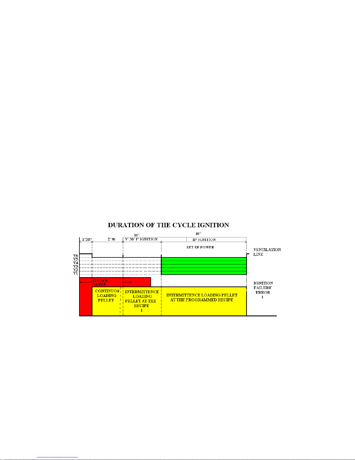
The ignition cycle can be explained as follows:
1. When ON is pressed on the control panel, the ign. torch will start to heat up as the
smoke exhaust fan starts at speed 6, for about 60 seconds.
2. The pellets begin to fall into the burner at a continuous rate for about 160 seconds.
3. The fan starts to work at 5 speed in order to reach the temperature setting for the
smoke temperature sensor.
4. At this point the ign. torch goes off and the fan smokes it works at the most (6
speed) for 3,30 minutes for to turn on the pellet.
5. The stove starts the selected recipe and power.
6. At temperatures below 3 ° C too low for the heating element to glow or temporary
non-functionality of the resistance can be used to ignite the firelighter. Insert a piece
of the crucible firelighter well lit, close the door and press ON / OFF.
IMPORTANT: the startup stage lasts 1 CYCLE of 27 minutes before signalling error 1. After this
stage the display will show the message Stove Lit, Automatic or Manual mode, Date and Time, and
it will be possible to make adjustments to the combustion. The stove is normally lit after 3 minutes.
IMPORTANT: the ROOM circulation fan will start as soon as the temperature of the exhaust smoke
will be 80°C.
If the stove is not lit within 1 cycle the message error1 will appear. The possible causes are:
No pellets
Pellets blocked
Grate obstructed by dirt
Faulty resistance (ign. torch).
9
Lighting the stove for the first time
The first time you light up the stove it will be necessary to wait about 5 minutes for the pellets in
the tank to reach the combustion chamber, because the cylinder containing the feed screw has to
be filled. So if 1 cycle is insufficient, switch off the stove and repeat the operation of lighting.
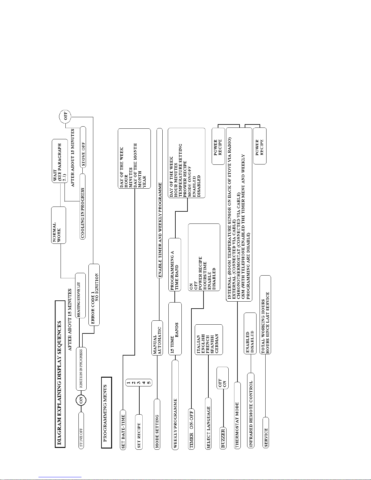
3.5 DIAGRAM EXPLAINING DISPLAY SEQUENCES
 Loading...