

Page 1
TM
FOCUS
INSTALLAT I O N A N D M A I N T E N A N C E
MANUA L
REVISION 2
P RO B E
Page 2

Focus TM Probe – OFM
Installation Manual
Contents:
1.0
Focus
1.1 Procedure – Installing Pipe Fittings ....................................................................................3
2.0 Focus TM Probe Pipe Fitting Installation – Hot Tap.......................................................4
3.0 Focus TM Probe Installation..............................................................................................6
3.1 Procedure – Installing the Safety Chain Clip:.....................................................................6
3.2 Procedure – Calculating Insertion Depth – 6” and Larger Pipes:........................................7
3.3 Procedure – Calculating Insertion Depth – 4” Pipe: ...........................................................8
3.4 Procedure – Installing the Focus TM Probe:.........................................................................9
3.5 Multi-fiber Cable Attachment...........................................................................................11
3.6 Heater Cable Attachment - Optional.................................................................................11
4.0 Focus TM Probe Removal ................................................................................................12
TM
Probe Pipe Fitting Installation.........................................................................3
4.1 Procedure – Removing the Focus TM Probe: .....................................................................12
5.0 Focus TM Probe Maintenance .........................................................................................13
2 Making Light Work ~ Photon Control Inc.
Page 3
1.0 Focus TM Probe Pipe Fitting Installation
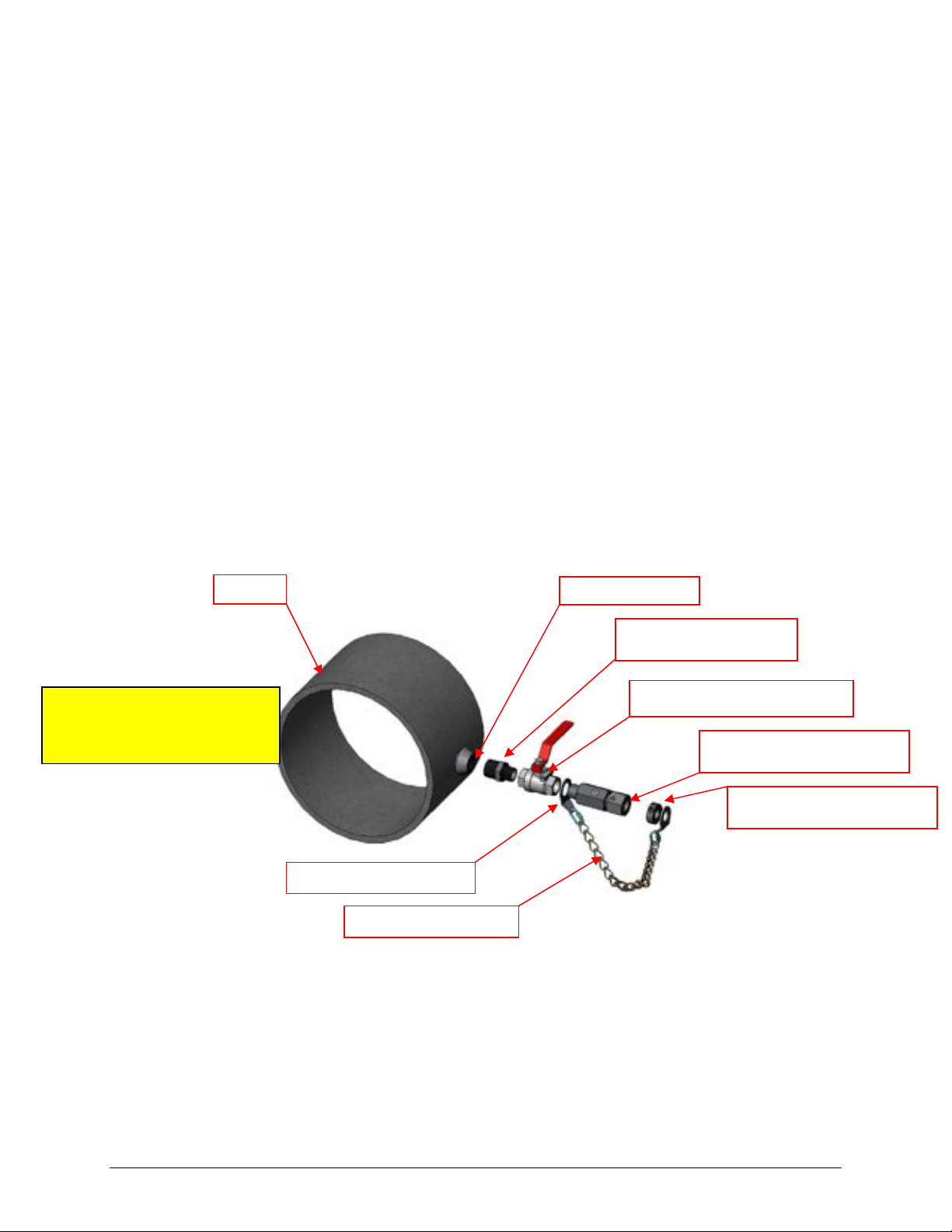
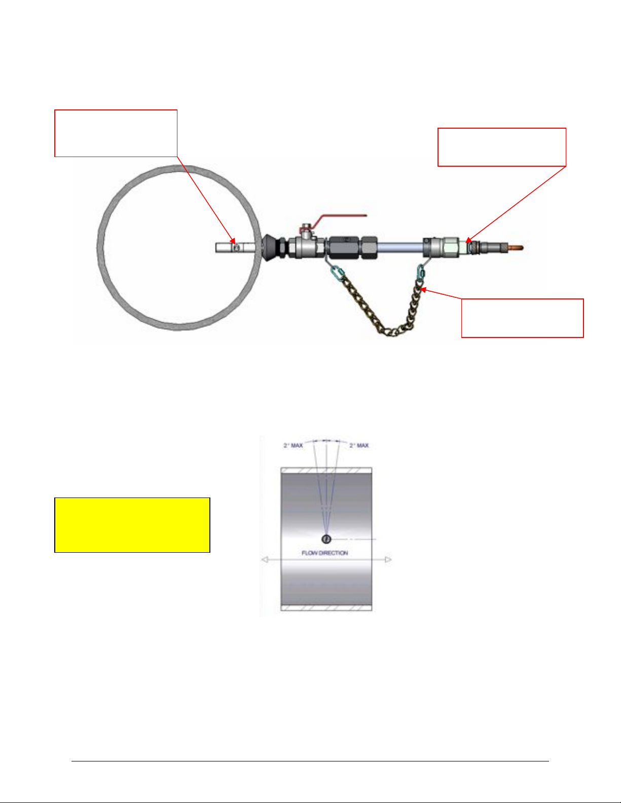
The instructions that follow are for installing the necessary fittings that will support the Focus
Probe flow meter. Figure 1 shows the components and may be used as a visual reference while installing
the fittings. The Focus
TM
Probe must never be installed in a vertical position where debris or moisture is
likely to settle on the optics. When installing into horizontal runs, position the fittings so that the probe
will be inserted at the 3 o’clock position. (Refer to
Figure 8) Mounting the probe horizontally will
minimize window-cleaning maintenance. Ensure that there is sufficient room around the pipe to install
and remove the insertion probe.
1.1 Procedure – Installing Pipe Fittings
1. Choose the location in the pipe that you want to install the Focus
2. Install a Threadolet with a 1” NPT thread.
3. Apply an appropriate pipe sealant and thread the 1” to ¾” Adapter into the weldolet and tighten.
4. Apply an appropriate pipe sealant and, holding the Ball Valve so the mounting holes and lever
point away from the pipe, thread the ¾” Ball Valve on to the Adapter and tighten.
5. Turn the Ball Valve to the off position. (Handle perpendicular to Ball Valve as shown)
6. Slide the Safety Chain Ring over the threading of the Packing Gland.
7. Apply an appropriate pipe sealant and thread the ¾” NPT Packing Gland into the Ball Valve and
tighten.
TM
Probe.
PIPE
1” Threadolet
1” TO ¾” ADAPTER
TM
NOTE:
1) Apply sealant to NPT threads
before installing.
Figure 1: Install Fittings as Shown in Diagram
¾” NPT ISOLATION VALVE
¾” NPT PACKING GLAND
¾” CLAMP COLLAR
SAFETY CHAIN RING
SAFETY CHAIN
Photon Control Inc. ~ Making Light Work 3
Page 4
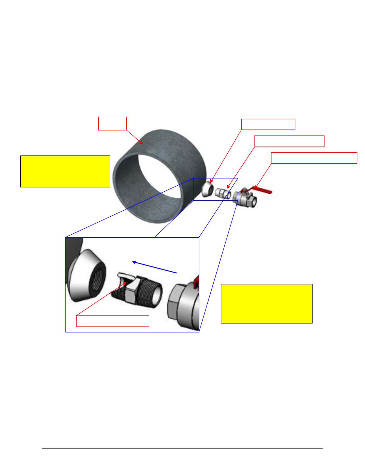
2.0 Focus TM Probe Pipe Fitting Installation – Hot Tap
1. Choose the location in the pipe that you want to install the Focus
2. Install a Threadolet with a 1” NPT thread.
3. Apply an appropriate pipe sealant and thread the 1” to 1” Nipple into the Threadolet and tighten.
4. Apply an appropriate pipe sealant and, holding the Ball Valve so the mounting holes and lever
point away from the pipe, thread the 1” Ball Valve on to the Nipple and tighten.
TM
Probe.
NOTE:
1) Apply sealant to NPT
threads before installing.
PIPE
1” Threadolet
1” TO 1” NIPPLE
1” NPT ISOLATION VALVE
NOTE:
Internal threads on 1” to 1” nipple
towards pipe
INTERNAL THREADS
Figure 2: Hot Tap Fitting Installation
5. Hot Tap Drill a 7/8” hole through the pipe wall.
6. Turn the Ball Valve to the “Off” position (handle perpendicular to valve body) when removing the
Hot Tap Drill from the pipe fittings.
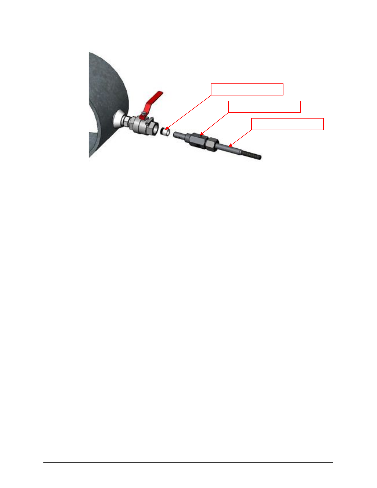
7. Slide the Hot Tap Tool into the Packing Gland with the dowel pin protruding on the threaded end.
4 Making Light Work ~ Photon Control Inc.
Page 5
SUPPORT SLEEVE
PACKING GLAND
HOT TAP TOOL
Figure 3: Inserting the support sleeve
8. Slide the Support Sleeve onto the Hot Tap Tool so the sleeves threads are toward the pipe as
shown in Figure 3.
9. Apply an appropriate pipe sealant and thread the Packing Gland into the Ball Valve and tighten.
10. Turn the Ball Valve to the “On” position (handle parallel to valve body)
11. Insert the hot tap tool through the valve and rotate it clockwise to thread the Support Sleeve into
the 1” to 1” Nipple until tight.
12. Back the Hot Tap Tool out of the pipe fittings until it stops against the Packing Gland.
13. Turn the Ball Valve to the “Off” position.
14. Unthread the Packing Gland from the Ball Valve to remove the Hot Tap Tool.
15. Slide the Safety Chain Ring over the threading of the Packing Gland. (Refer to Figure 1 for Safety
Chain placement)
16. Reapply an appropriate pipe sealant and thread the 1” NPT Packing Gland into the Ball Valve and
tighten.
17. Refer to Section 3.0 for flow meter installation.
Photon Control Inc. ~ Making Light Work 5
Page 6
3.0 Focus TM Probe Installation
The instructions in this section cover the installation of the Focus
to retain the probe. Figure 4 through
Diameters
provide visual aids for the installation procedures.
Figure 6: Insertion Depth Calculations for 4" and Smaller Pipe
At no time during the installation should any person position any part of their body in line with the probe.
A pressurized pipe could cause the probe to accelerate outwards causing bodily harm.
Small leakages may occur during installation. Take appropriate safety precautions.
Install only under minimal operating pressure or with the line shut off to prevent large forces acting on the
probe.
NOTE:
Maximum Force Acting on Probe =
Line Pressure (psig) x 0.44
Examples:
30psig x 0.44 = 13lbs
100psig x 0.44 = 44lbs
NOTE:
Process operating pressure and temperature
restrictions:
Max Pressure: 100psig
Temp. Range: -40ºF to +302ºF (-40ºC to +150ºC)
3.1 Procedure – Installing the Safety Chain Clip:
TM
Probe and the safety hardware used
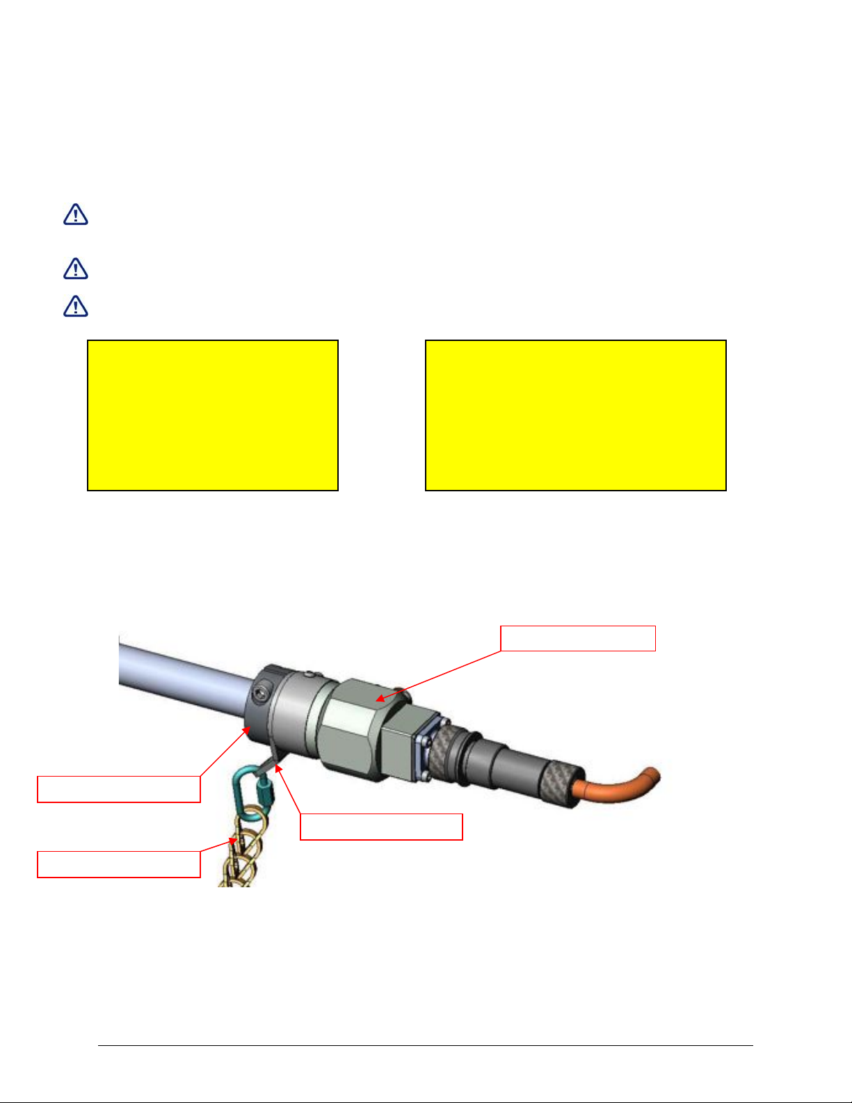
1. Undo the Quick Link connector and remove the Safety Chain from the Safety Chain Clip.
2. Slide the Safety Chain Clip on to the probe so the tab points away from the Fiber Connector at the
3. Slide a Clamp-On Collar on to the probe and position it so it secures the Safety Chain Clip against
4. Tighten the screw on the Clamp-On Collar with a 3/16” Allen wrench.
CLAMP-ON COLLAR
SAFETY CHAIN
Figure 4: Install Safety Chain Clip and Clamp-On Collar as Shown
end of the probe.
the Fiber Connector.
FIBER CONNECTOR
SAFETY CHAIN CLIP
6 Making Light Work ~ Photon Control Inc.
Page 7
3.2 Procedure – Calculating Insertion Depth – 6” and Larger Pipes:
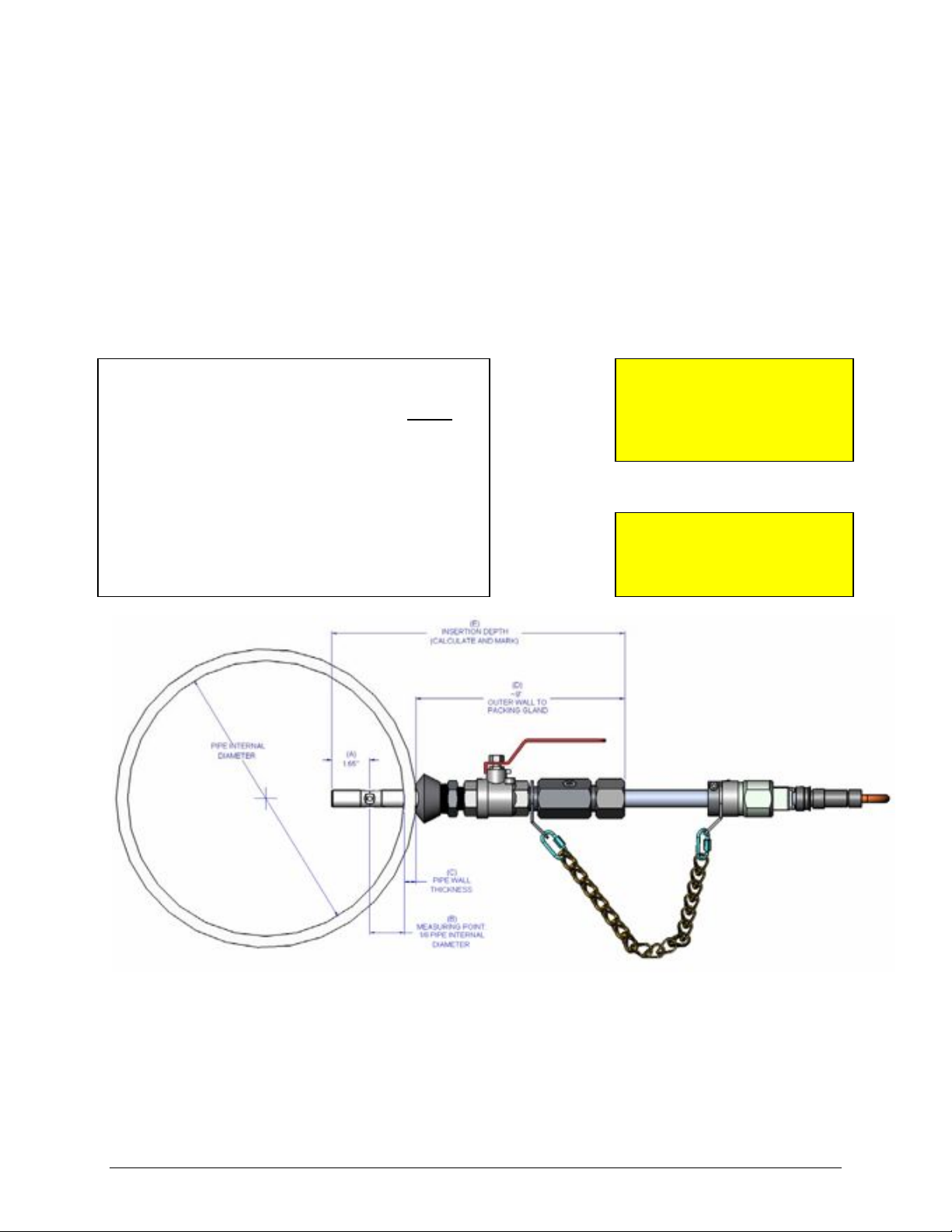
Before progressing with the installation of the probe it is necessary to calculate and mark the
correct insertion depth. The actual measuring point for the Focus TM Probe is 1.65” (42mm)
from the end of the probe. For 6” and larger pipe diameters this measuring point should be
positioned at the quarter radius point of the pipe for accurate readings. This is calculated using
the following method. Refer to Figure 5 for a diagram of the measurements to be taken.
1. Measure and record distances A, B, C and D.
2. Calculate and record distance E = A+B+C+D. (Keep this record for future reference as it will be
needed for reinstallation should the probe be removed.)
3. Mark the probe at distance E from the probe end as shown.
M
easure and record the following:
A = End to Measuring Point = 1.65” +
B = 0.125 x Pipe ID = _____ +
C = Pipe Wall Thickness = _____ +
D = Outer Wall to Packing Gland = _____ =
E = Insertion Depth = A+B+C+D = _____
NOTE:
Pipe internal diameter and wall
thickness may be found in
Appendix A.
NOTE:
Insertion depth tolerance: ±0.5%
of nominal pipe size.
Figure 5: Insertion Depth Calculations for 6” and Larger Pipe Diameters
Photon Control Inc. ~ Making Light Work 7
Page 8
3.3 Procedure – Calculating Insertion Depth – 4” Pipe:
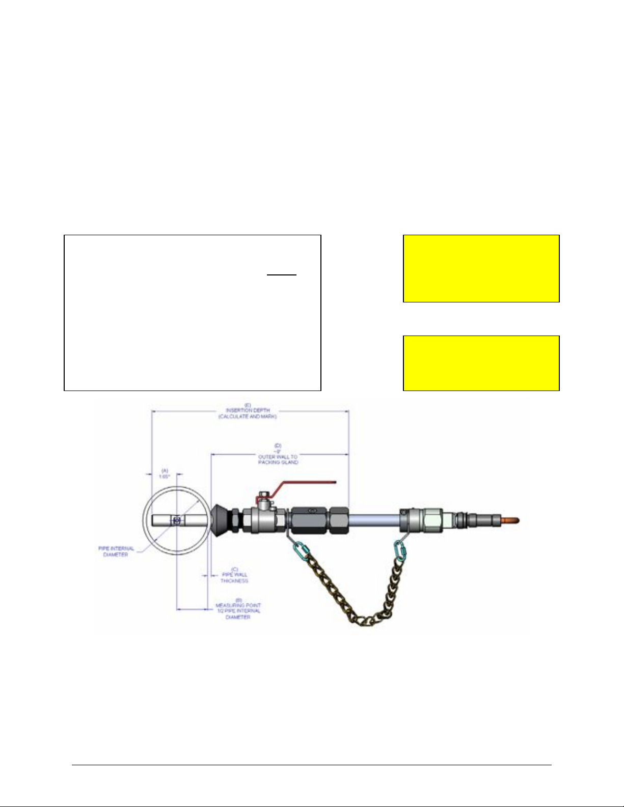
Before progressing with the installation of the probe it is necessary to calculate and mark the
correct insertion depth. The actual measuring point for the Focus TM Probe is 1.65” (42mm)
from the end of the probe. For a 4” pipe diameter this measuring point should be positioned at
the center point for accurate readings. This is calculated using the following method. Refer to
Figure 5 for a diagram of the measurements to be taken.
1. Measure and record distances A, B, C and D.
2. Calculate and record distance E = A+B+C+D. (Keep this record for future reference as it will be
needed for reinstallation should the probe be removed.)
3. Mark the probe at distance E from the probe end as shown.
M
easure and record the following:
A = End to Measuring Point = 1.65” +
B = 0.5 x Pipe ID = _____ +
C = Pipe Wall Thickness = _____ +
D = Outer Wall to Packing Gland = _____ =
E = Insertion Depth = A+B+C+D = _____
NOTE:
Pipe internal diameter and wall
thickness may be found in
Appendix A.
NOTE:
Insertion depth tolerance: ±0.5%
of nominal pipe size.
Figure 6: Insertion Depth Calculations for 4" and Smaller Pipe Diameters
8 Making Light Work ~ Photon Control Inc.
Page 9
3.4 Procedure – Installing the Focus
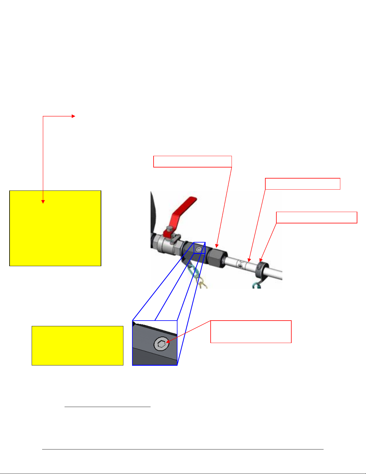
1. Ensure the Ball Valve is in the OFF position. (Handle perpendicular to Ball Valve as shown)
2. Loosen the Packing Gland Nut to allow the probe to slide through.
3. Slide the probe through the Packing Gland until it gently rests against the closed ball valve. (An
o-ring in the packing gland will seal against the probe body)
4. Connect the Quick Link and Safety Chain to the Safety Chain Clip.
5. Adjust length of Safety Chain until it is tight.
6. Orient probe flats parallel to flow direction as shown in Figure 8.
7. Turn the ball valve to the ON position. (Handle parallel to Ball Valve)
8. Push the probe through to the quarter radius depth marked in Procedure 3.2 or center point marked
in Procedure 3.3 as applicable.
9. Tighten the Packing Gland Nut to 55-60in-lbs to ensure solid retention.
NOTE:
Ensure the probe is oriented so
that the cutout in the probe is
parallel to the flow direction in
the pipe. Use the flat surface of
the Fiber connector as a visual
reference and DO NOT allow the
probe to rotate once orientation is
established.
TM
Probe:
PACKING GLAND NUT
FOCUS TMPROBE - OFM
CLAMP-ON COLLAR
Figure 7: Inserting the Probe into the Pipe Fittings
NOTE:
DO NOT REMOVE PLUG
WHILE BALL VALVE IS IN
THE OPEN POSITION
*
A purge nipple may be added as needed by the customer during installation of the flow meter. This would
allow for safe expulsion of gases trapped between the ball valve and packing gland seal during removal.
Photon Control Inc. ~ Making Light Work 9
*
¼” NPT port for optional
purge nipple*
Page 10
PROBE FLOW TUBE
PARALLEL TO FLOW
DIRECTION
Figure 8: Fully Installed Focus
TM
ORIENTATION
REFERENCE SURFACE
SAFETY CHAIN AND
QUICK-LINKS
Probe
NOTE:
MAXIMUM ERROR IN
ROTATION ALIGNMENT ±2º
Figure 9: Probe Orientation to Flow Direction
10 Making Light Work ~ Photon Control Inc.
Page 11
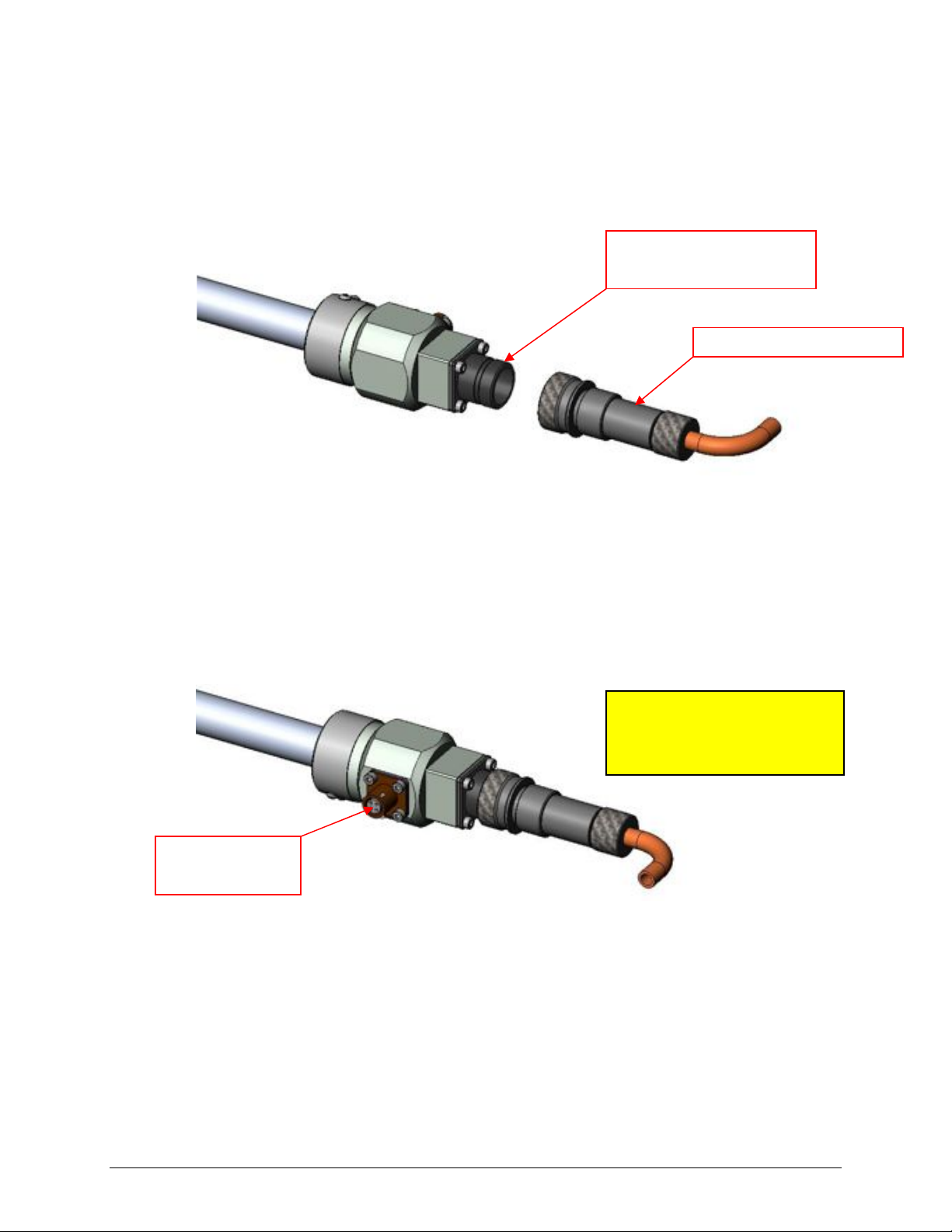
3.5 Multi-fiber Cable Attachment
r
1. Remove the cap from the TFOL Connector Bulkhead.
2. Line up the connector grooves and thread the TFOL Connector onto the Bulkhead until tight.
Figure 10: Attaching the TFOL Multi-Fiber Connector
TFOL Connector
Bulkhead
TFOL Connecto
3.6 Heater Cable Attachment - Optional
1. Line up the four pins and connect the Heater Receptacle to Supply Cable
Heater Connector
Receptacle
Figure 11: Optional Heater Connector
NOTE:
Optional heated window for wet
processes.
Photon Control Inc. ~ Making Light Work 11
Page 12
4.0 Focus TM Probe Removal
At no time during the removal should any person position any part of their body in line with the
probe. A pressurized pipe could cause the probe to accelerate outwards causing bodily harm.
Ensure safety chain is attached to prevent blow out.
Small leakages may occur during removal. Take appropriate safety precautions.
Remove only under minimal operating pressure or with the line shut off to prevent large forces
acting on the probe. (Refer to section 3.0 Focus
acting on the probe due to pressure)
4.1 Procedure – Removing the Focus TM Probe:
1. Mark the probe at the point where it emerges from the Packing Gland as a reference for
reinstallation.
2. Holding the probe to prevent it from pushing out, loosen the Packing Gland Nut just enough to
allow for movement of the probe.
3. Pull the probe out of the Pipe until the Safety Chain becomes tight.
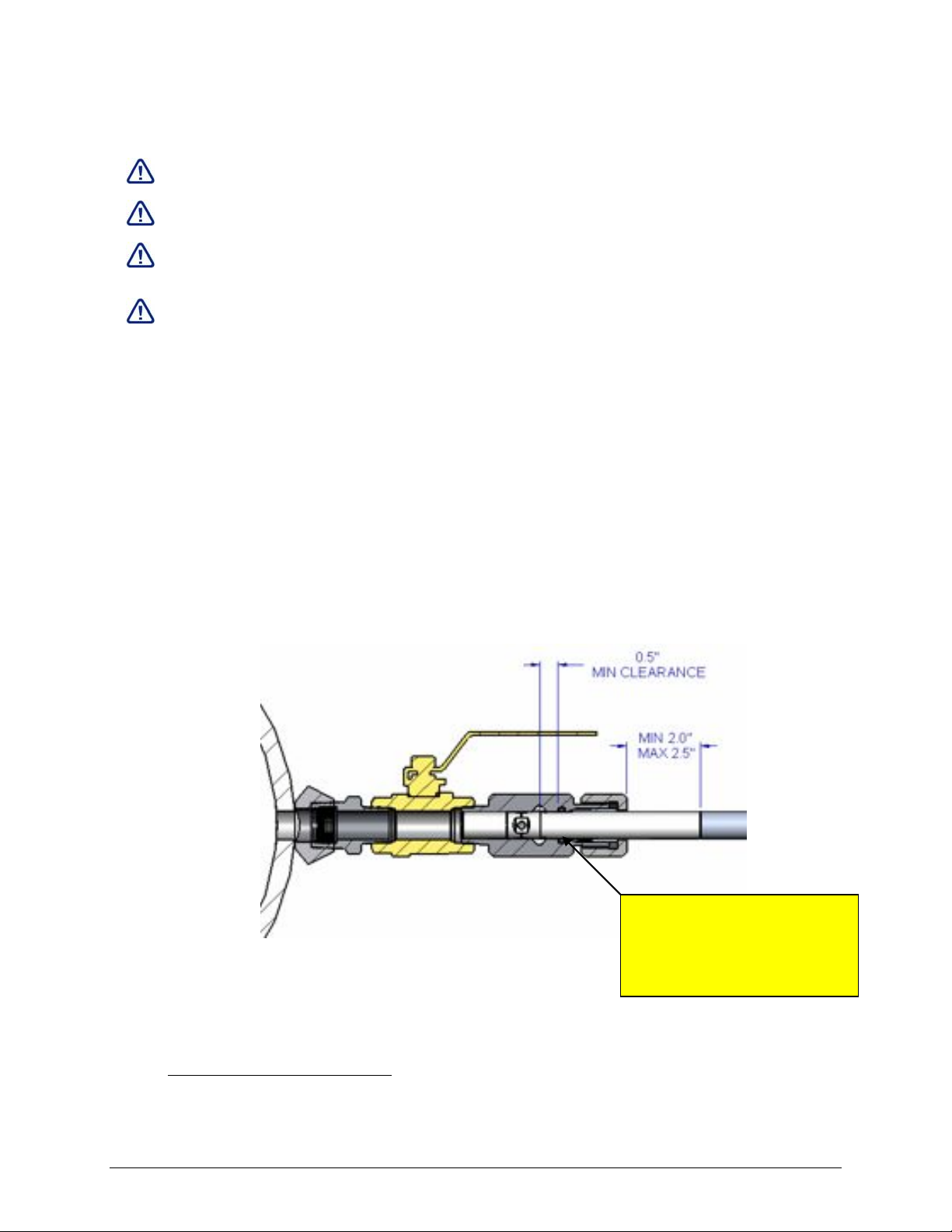
a. In the event the Safety Chain length was altered ensure the seam of the probe is between
2.0” and 2.5” from the Packing Gland. This will prevent seal failure.
4. Turn the Ball Valve to the OFF position.
5. Purge trapped gases using purge nipple.
6. Loosen the Packing Gland Nut so the probe moves freely within the fittings.
7. Slide the probe in the fittings until it gently rests against the closed Ball Valve.
8. Remove the Safety Chain from the Safety Chain Clip.
9. Remove the Focus
TM
Probe completely from the fittings.
TM
Probe Installation for examples on the force
*
NOTE:
Figure 12: Minimum and Maximum Extraction Distance for Probe
*
Optional step only required where purge nipple installed. (Refer to Section 3.4)
12 Making Light Work ~ Photon Control Inc.
Inspect O-ring for cracks and
wear after each removal and
replace as necessary.
Page 13
5.0 Focus TM Probe Maintenance
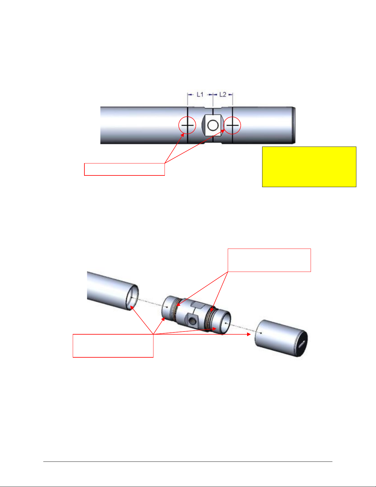
1. Check that alignment scribe marks are present on the flow meter as shown in Figure 13.
Alignment Scribe Marks.
Figure 13: Alignment Scribe Marks on Insertion Probe Components
2. Disassemble the 3 main components of the flow meter as shown in Figure 14 by unscrewing
counterclockwise.
3. Inspect o-rings for wear and cracks and replace as necessary.
4. Inspect all thread surfaces for burrs and dirt. Deburr and clean thoroughly before reassembly.
NOTE:
Ensure that scribe marks are
aligned and that L2 is toward the
tip on reassembly.
Deburr and clean threads
before reassembly
Figure 14: Disassemble 3 Main Components to Access Optics for Cleaning
Inspect o-rings and replace if
cracked, split or worn.
Photon Control Inc. ~ Making Light Work 13
Page 14
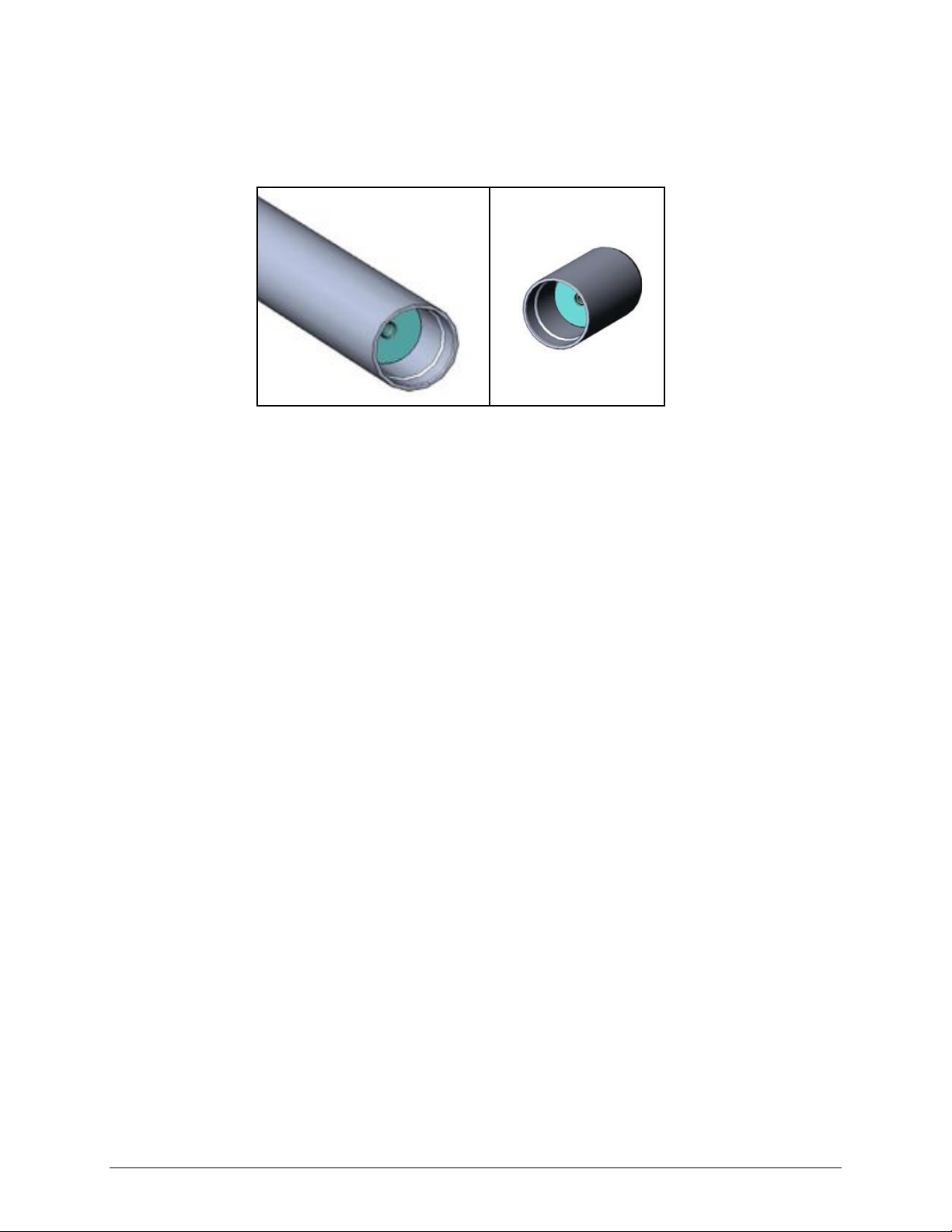
5. Inspect optical surfaces shown in Figure 15 for fouling and clean using alcohol, a clean cloth and a
q-tip.
Figure 15: Carefully Clean Optical Surfaces With a Clean Cloth and Q-Tip
6. Reassemble probe components ensuring that the shorter portion of the center piece is towards the
tip of the flow meter as shown in Figure 13. Use a removable threadlocker on threads.
!!ENSURE SCRIBE MARKS LINE UP ON REASSEMBLY!!
14 Making Light Work ~ Photon Control Inc.
Page 15
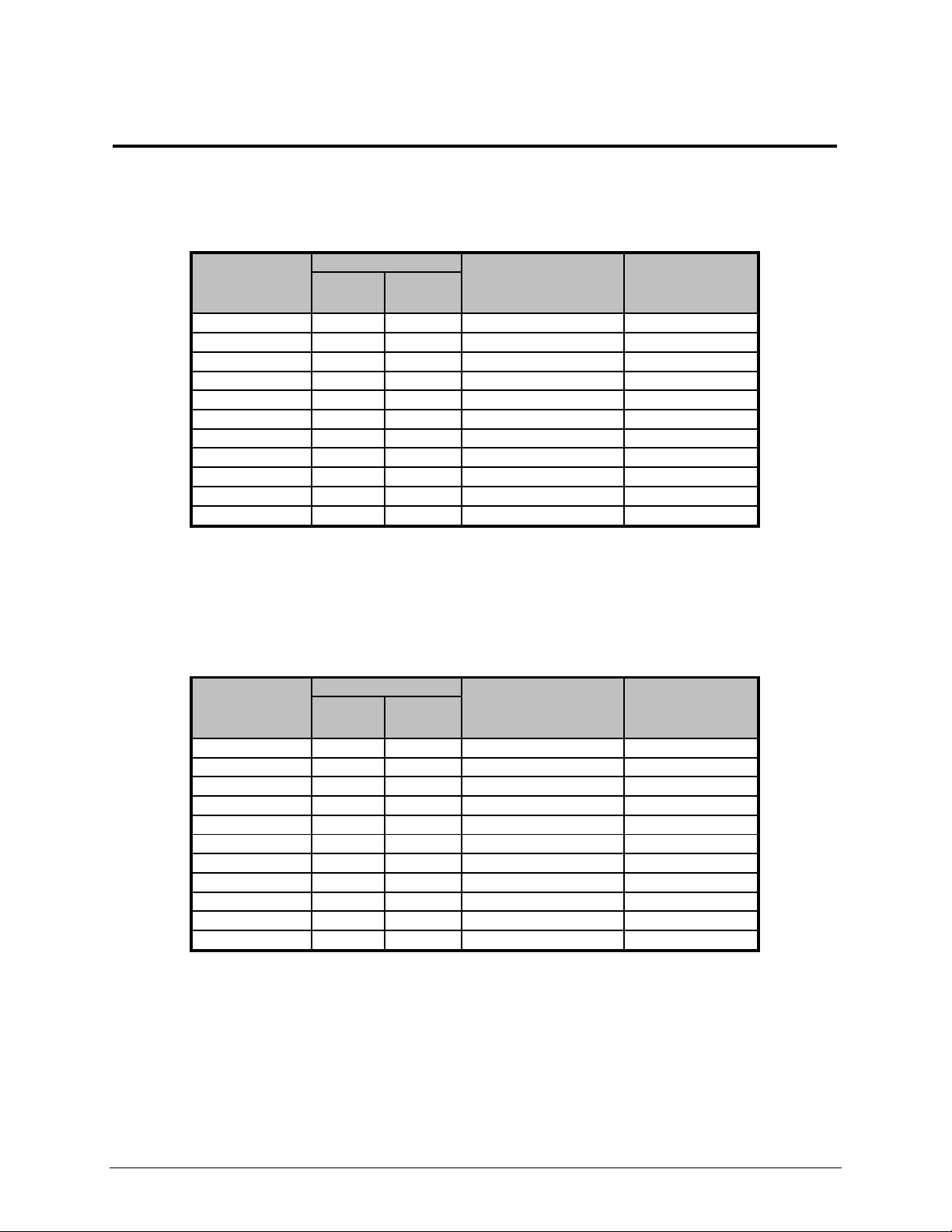
APPENDIX A - STEEL PIPE DIMENSIONS
Table 1: Steel Pipe Di mensions - ANSI Schedule 80
Pipe Size (inches)
4 4.50 3.83 0.34
5 5.56 4.81 0.38
6 6.63 5.76 0.43
8 8.63 7.63 0.50
10 10.75 9.56 0.59
12 12.75 11.38 0.69
14 14.00 12.50 0.75
16 16.00 14.31 0.84
18 18.00 16.13 0.94
20 20.00 17.94 1.03
24 24.00 21.56 1.22
Table 2: Steel Pipe Di mensions - ANSI Schedule 40
Pipe Size (inches)
4 4.50 4.03 0.24
5 5.56 5.05 0.26
6 6.63 6.07 0.28
8 8.63 7.98 0.32
10 10.75 10.02 0.37
12 12.75 11.94 0.41
14 14.00 13.13 0.44
16 16.00 15.00 0.50
18 18.00 16.88 0.56
20 20.00 18.81 0.59
24 24.00 22.63 0.69
Diameter (inches)
External Internal
Diameter (inches)
External Internal
Nominal Thickness
(inches)
Nominal Thickness
(inches)
1/8 Pipe Internal
Diameter
(inches)
1.92**
2.41**
0.72
0.95
1.20
1.42
1.56
1.79
2.02
2.24
2.70
1/8 Pipe Internal
Diameter
(inches)
2.02**
2.53**
0.76
1.00
1.25
1.49
1.64
1.88
2.11
2.35
2.83
** These dimensions are 1/2 the Pipe Internal Diameter
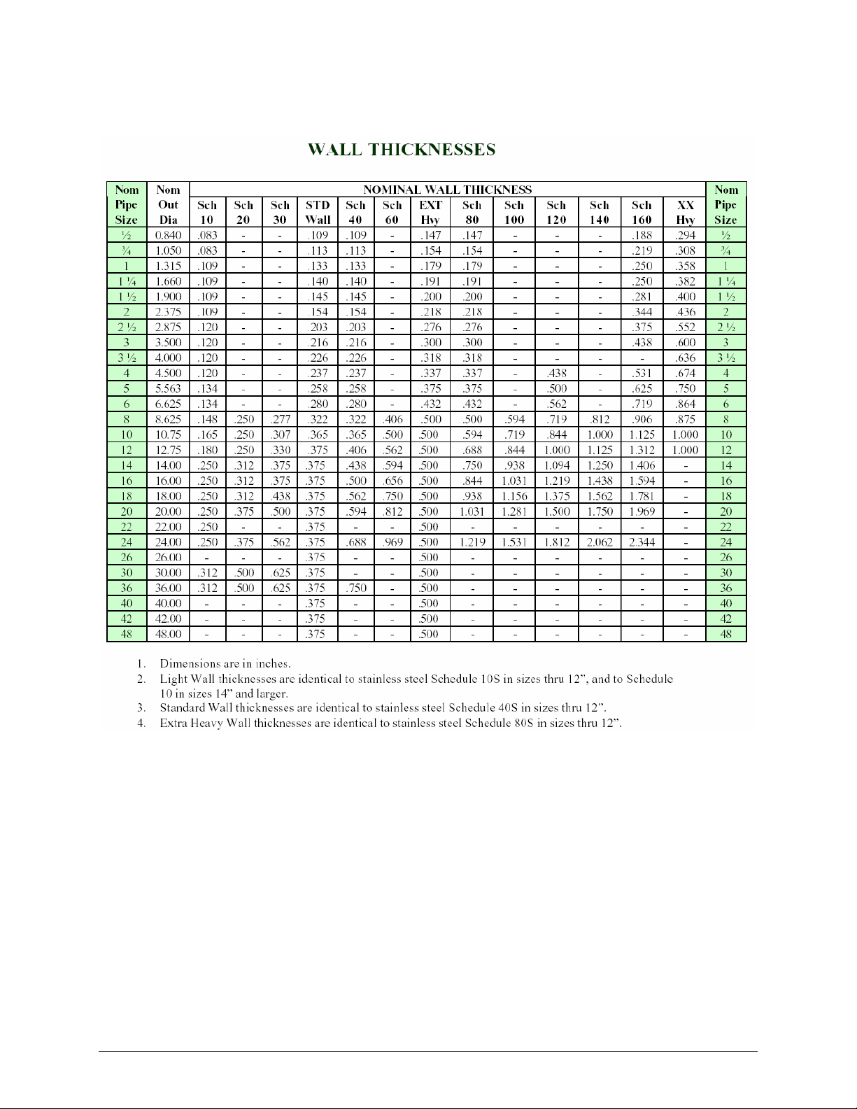
For other pipe sizes refer to the table on the next page.
Photon Control Inc. ~ Making Light Work 15
Page 16
16 Making Light Work ~ Photon Control Inc.
Page 17
r
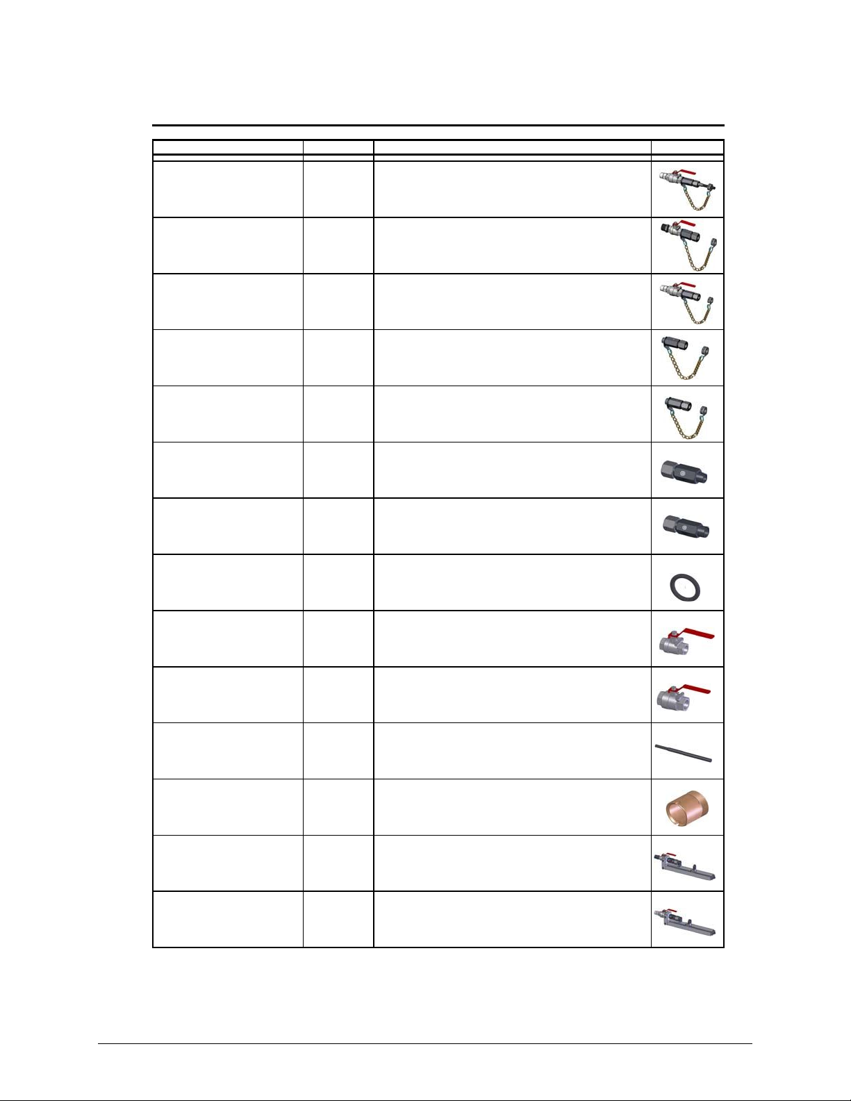
APPENDIX B - PARTS LIST
Product Name Part Numbe
OFA-KIT-1in HOT TAP ASY-0221A
OFA-VAS-3/4-VIT ASY-0219A
OFA-VAS-1-VIT ASY-0220A
OFA-PGA-3/4 ASY-0216A Safety Chain with Clips, 3/4" NPT Packing Gland
OFA-PGA-1 ASY-0218A Safety Chain with Clips, 1" NPT Packing Gland
ACC-3/4Iin GLAND ASY-0178B 3/4" NPT Packing Gland
ACC-1in GLAND ASY-0243B 1" NPT Packing Gland
1" to 1" NPT Nipple, PEEK Bushing, Safety Chain with
Clips, 1" Full Port Ball Valve, 1" NPT Packing Gland,
Hot Tap Insertion Tool
3/4" to 1" NPT Adapter, Teflon Bushing, Safety Chain
with Clips, 3/4" Full Port Ball Valve, 3/4" NPT Packing
Gland
1" to 1" NPT Nipple, PEEK Bushing, Safety Chain with
Clips, 1" Full Port Ball Valve, 1" NPT Packing Gland
Description Image
ACC-ORING-VITON MGK-0036Z O-RING 2-210 VITON V0835
ACC-3/4in VALVE MMM-0058Z 3/4" FNPT - FNPT BALL VALVE
ACC-1in VALVE MMM-0068Z 1" FNPT - FNPT BALL VALVE
ACC-HOT TAP TOOL ASY-0198A Hot Tap Insertion Tool
ACC-PEEK BUSHING MMC-0391A PEEK Bushing
OFA-TOOL-INS-3/4 ASY-0252A
OFA-TOOL-INS-1 ASY-0253A
3/4" to 1" NPT Adapter, Teflon Bushing, 3/4" Full Port
Ball Valve, 3/4" NPT Packing Gland, High Pressure
Retraction Device
1" to 1" NPT Nipple, PEEK Bushing, 1" Full Port Ball
Valve, 1" NPT Packing Gland, High Pressure
Retraction Device
Photon Control Inc. ~ Making Light Work 17
 Loading...