

Page 1
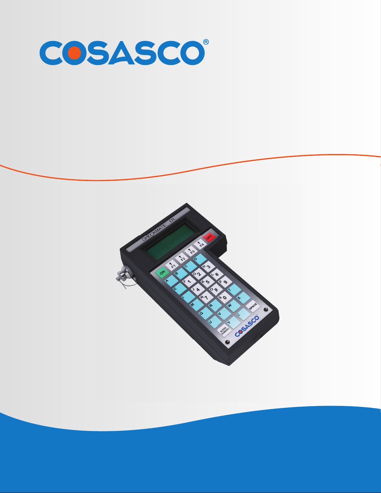
CHECKMATE™ DL
Reference Manual
11841 Smith Avenue
Santa Fe Springs, CA 90670
Tel: (562) 949-0123 • (800) 635-6898
Fax: (562) 949-3065
P/N: 723700-Manual Rev G
www.cosasco.com
Page 2
CHECKMATE™ DL is a trademark of Rohrback Cosasco Systems, Inc. CORROSOMETER®, CORRDATA®, MICROCOR®, MICROCOR ® TOOLS ,and CORRDATA® PLUS
are registered trademarks of Rohrback Cosasco Systems, Inc.
Windows® is a trademark of Microsoft Corporation.
No part of this manual may be reproduced or transmitted in any form or by any means,
electronic or mechanical, including photocopying and recording, for any purpose, without
the express written permission of Rohrback Cosasco Systems, Inc.
Page 3

CHECKMATE™ DL
Table of Contents
Chapter 1 Introduction ............................................................................1
Chapter 2 Specifi cations .........................................................................3
Checkmate DL Instrument.......................................................................................3
Electrical..................................................................................................................3
Hazardous Area Certifi cation...................................................................................3
Intrinsic Safety.........................................................................................................4
i
Chapter 3 Basics of Checkmate DL ..................................................5
Contents and Unpacking........................................................................................5
Battery Installation..................................................................................................5
Checking Battery Status.........................................................................................6
Standby Screens of Checkmate DL.......................................................................7
Available Memory Space and Standard Time Zone...............................................7
Checkmate DL Keypad..........................................................................................8
Checkmate DL Firmware Version..........................................................................8
Standby Display Screens for Microcor and Corrdata Systems..............................9
Chapter 4 Initializing Checkmate DL to Work with Corrdata System ..11
Confi guring Checkmate DL for Corrdata Systems...............................................11
Setting the Time and Date...................................................................................11
Setting the Engineering Units..............................................................................12
Clearing Memory on Checkmate DL....................................................................13
Changing the Communication Baud Rate............................................................13
Chapter 5 Confi guring Checkmate DL with RDC/ER-210 Confi guration ...15
Import RDC/ER-210 Confi gurations to Checkmate DL using a PC and Corrdata Plus.......15
Manually Set RDC/ER-210 Confi gurations to Checkmate DL................................16
Page 4

TABLE OF CONTENTS
ii
Chapter 6 Confi guring a RDC/ER-210 Using Checkmate DL ...................25
Setting the Date and Time on RDCs/ER-210s.....................................................25
Confi gure a RDC/ER-210 using the Checkmate DL..............................................26
Updating RDC/ER-210 Confi guration upon Probe Replacement...........................28
Confi guration of 4 Channel RDC..........................................................................29
Chapter 7 Reading a RDC/ER-210 with the Checkmate DL .....................33
Data Collection from a RDC/ER-210 .....................................................................33
Reading the RDC Confi guration Details...............................................................34
Reading the Programmed Date and Time on the RDC........................................35
Perform a “Test Read” on a RDC.........................................................................36
Display the “Test Read” Results...........................................................................37
Chapter 8 Displaying RDC/ER-210 Data on the Checkmate DL ...............39
Chapter 9 Transferring RDC/ER-210 Data to the PC ..................................41
Corrdata Plus Installation....................................................................................41
Confi guring Corrdata Plus...................................................................................41
Connecting the Checkmate DL to the PC............................................................41
Checkmate DL Data Transfer Procedure.............................................................41
Chapter 10 Initializing Checkmate DL for Microcor Systems ..................45
Confi guring Checkmate DL for Microcor Systems.............................................45
Setting the Time and Date.................................................................................45
Clearing the Checkmate DL Memory.................................................................46
Chapter 11 Confi guring and Programming Microcor Data Loggers ....47
Set Data Logger Confi gurations to Checkmate DL and Program Data Logger.........47
Set Data Logger Time.......................................................................................48
Chapter 12 Reading a Data Logger with the Checkmate DL ...................49
Read Data Logger Confi guration and Status...................................................49
Reading / Clearing Data from Microcor Data Loggers.....................................49
Page 5

CHECKMATE™ DL
Chapter 13 Transferring Data Logger Data to the PC ............................53
Microcor Tools Installation....................................................................................53
Confi guring Microcor Tools...................................................................................53
Connecting the Checkmate DL to the PC.............................................................53
Checkmate DL Data Transfer Procedure..............................................................53
Chapter 14 Troubleshooting Guide ..........................................................57
Appendix A EC Type Examination Certificate ..........................................59
Appendix B Interconnect Diagram Drawing.............................................63
iii
Page 6

TABLE OF CONTENTS
iv
Page 7

CHECKMATE™ DL
FIGURES and TABLES
Figure 1.1 Checkmate DL Instrument ....................................................1
Figure 1.2 Checkmate DL Instrument Specifi cations .........................2
Figure 3.1 Battery Cover of Checkmate DL Instrument .....................6
i
Figure 3.2 Checkmate DL Function Keys .............................................8
Table 5.1 CORROSOMETER and CORROTEMP Probe Types and Spans 23
Table 5.2 Alloy Multipliers .................................................................24
Figure B.1 Interconnect Diagram Drawing ..........................................63
Page 8

FIGURES AND TABLES
ii
Page 9
CHECKMATE™ DL 1
Introduction CHAPTER 1
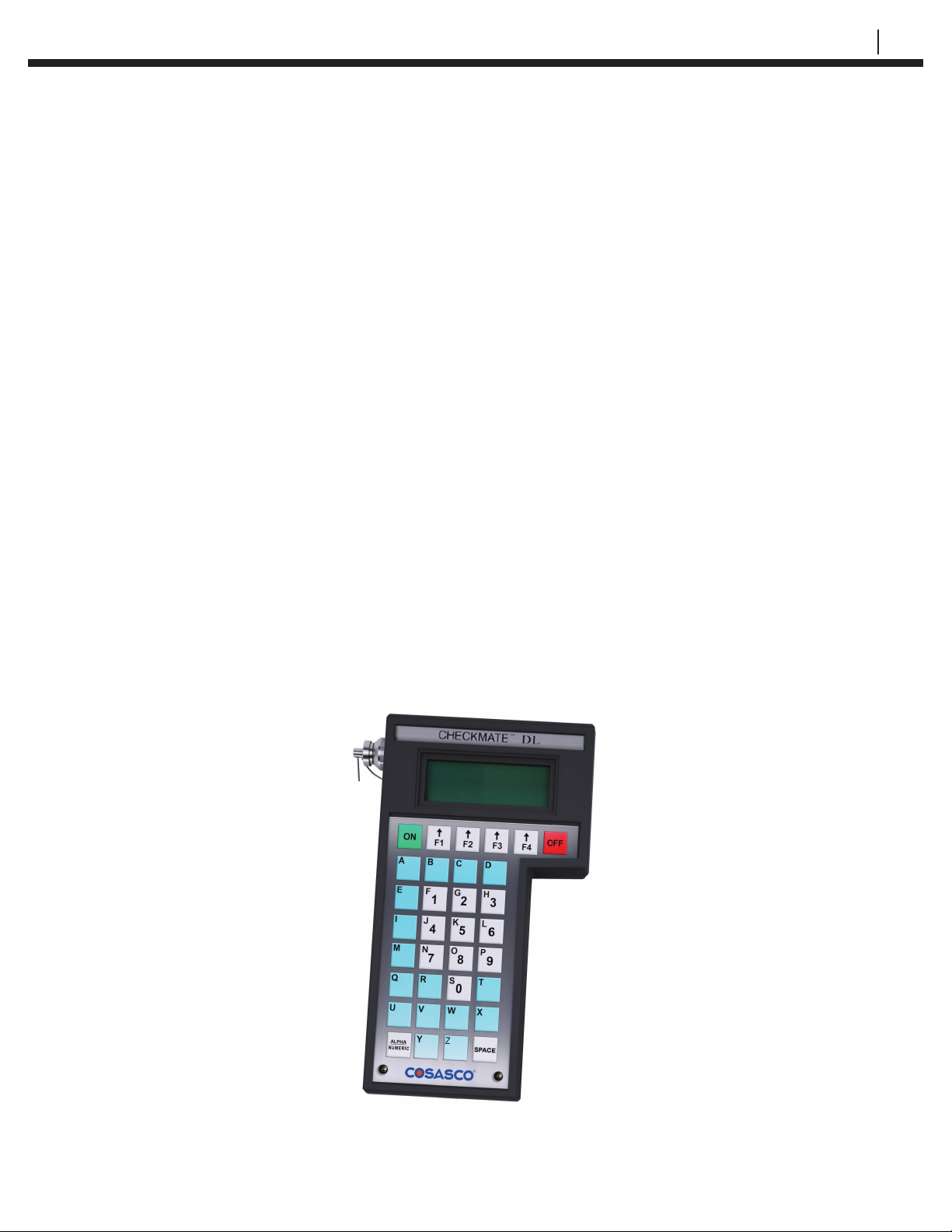
The Checkmate™ DL handheld instrument is the convenient and hassle-free way
to program and collect data from Microcor Data Loggers or Corrosometer and
Corrater Remote Data Collectors (RDCs). Checkmate DL can be programmed to
operate with either technology with only a few keypad entries. This portable unit
can store readings of up to 50 different Microcor Data Loggers or Corrosometer
and Corrater RDCs. The intrinsically safe communication between the
instrument and Data Loggers or RDCs enables the user to collect data without
moving the Data Logger or RDC to a safe area. Furthermore, the Checkmate
DL makes transferring stored data to a PC a much simpler process than before,
using the Corrdata Plus® Corrosion Management Software or the Microcor Tools
Software. Refer to Appendix A for Typical System Confi guration.
Figure 1.1 Checkmate DL Instrument
Page 10
2 INTRODUCTION
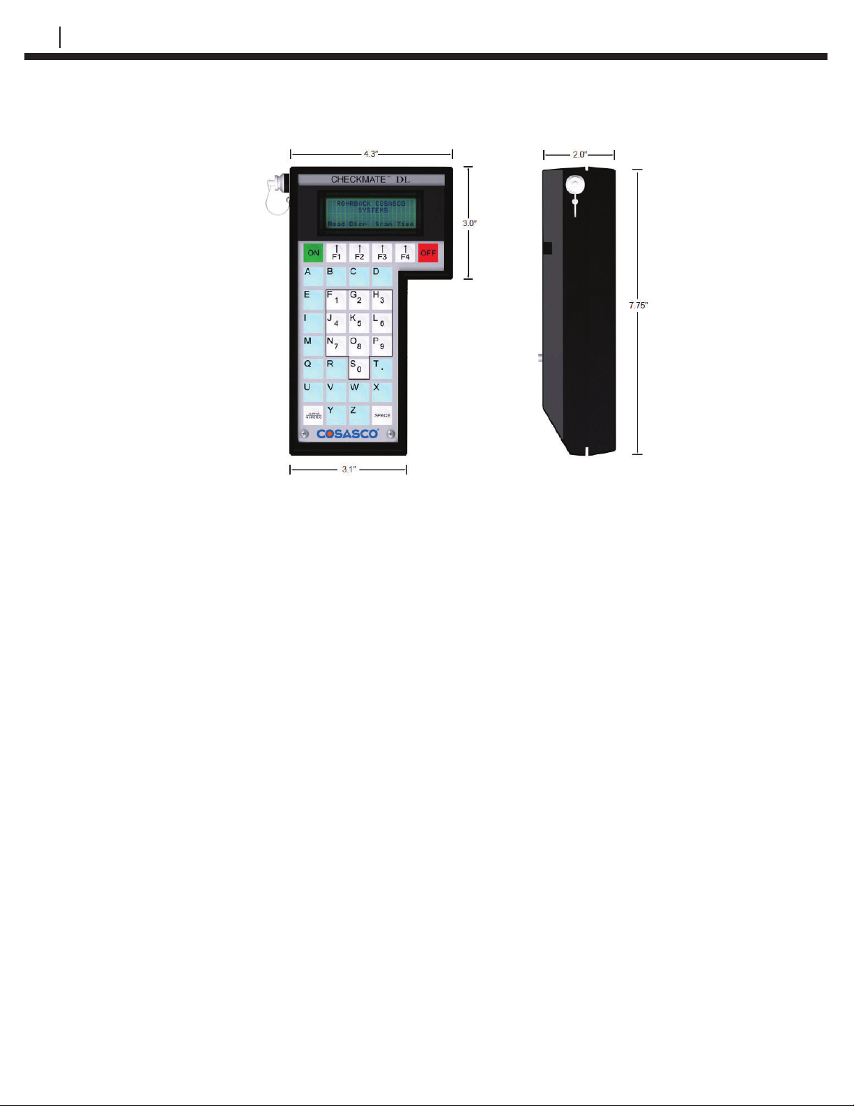
Figure 1.2 Checkmate DL Instrument Specifi cations
Page 11

CHECKMATE™ DL 3
Specifi cations CHAPTER 2
Checkmate DL Instrument
• Dimensions: 7.75”H x 4.30”W x 2”D ( 196.8 mm x 109.2 mm x 50.8 mm )
• Weight: 1.5 lb. ( 0.68 kg )
• Temperature range:
Operating - 0ºF to 122ºF ( -18ºC to 50ºC )
Storage - 0ºF to 150ºF ( -18ºC to 70ºC )
• Splash-proof enclosure with sealed membrane keyboard
Electrical
• Compatible with all Corrosometer® RDC/ER-210 units
• Compatible with all Corrater® RDC units
• Compatible with all Microcor® Data Loggers
• Memory for up to 50 RDCs when programmed for Corrdata Systems
• 57,330 Microcor Data Logger Readings when programmed for Microcor Systems
• Automatic power shutoff 2 minutes after read completion or idling
• Four-Line Liquid Crystal Display (LCD)
• Power Supply: 6 AA Alkaline cells
• Battery Life: Typically 10 hours (continuous operation)
• Data Transfer: Intrinsically Safe RS232 protocol at 9600 Baud Rate
Hazardous Area Certifi cation
• Model CHECKMATE™ DL-1-Y: Class 1, Zone 1
CE compliant (EMC, ATEX)
ATEX/IECEx Ex ib IIC T4 Gb, -20ºC ≤ Tamb ≤ +50ºC
• DEMKO 07 ATEX 0707396X
• IECEx UL 18.0129X
• ATEX/IEC Explosive Atmospheres, General Requirements IEC/EN 60079-0
(6th edition)
• ATEX/IEC Explosive Atmospheres, Equipment Protection by Intrinsic
Safety “i”
IEC/EN 60079-11 (6th edition)
Page 12

4 SPECIFICATIONS
Intrinsic Safety
The gas classifi cation IIC is the most stringent including gases such as acetylene
and hydrogen. This part of the rating relates to the spark energy that is required
to create an explosion.
Gases have a separate classifi cation for explosive tendency based on hot
surface temperatures which are not necessarily the same as the spark ignition
energy. The temperature rating T4 indicates that no temperature of the
equipment exceeds 1350C at 500C ambient temperature even under fault
conditions. This rating includes all listed gases except carbon disulfi de (which
requires T5 rating)
Care must be taken with intrinsically safe systems to maintain their carefully
designed integrity. The major features to note:
1. The instrument is intrinsically safe when used with six 1.5V, size AA alkaline
batteries: Duracell MN1500, Energizer E91 or EN91, or Ray-O-Vac 815.
Batteries must be changed only in a non-hazardous area. Do not mix
batteries of different age or part number.
2. Absolutely no substitution of parts or unauthorized repairs may be
undertaken or the certifi cations are rendered invalid.
3. Only the intrinsically safe cables provided by Rohrback Cosasco
Systems, Inc. should be used between the instrument and the PC
(even when in safe areas). This prevents any excess power from
being passed onto the instrument, which could then be carried into the
hazardous area.
Page 13

CHECKMATE™ DL 5
Basics of Checkmate DL CHAPTER 3
Contents and Unpacking
Carefully remove the instrument from its package. Included in the package you
should fi nd:
• Checkmate DL Instrument (P/N 723701)
• 6 AA batteries
• USB Drive
• Converter, USB to RS232 (P/N 090753)
• Adapter, DB25 to DB9 (P/N 748072)
• Cable Assembly for Microcor ML-9500B Data Logger (P/N 748241)
• Cable Assembly for Checkmate DL to Computer (P/N 723725)
• Cable Adapter for Checkmate DL to RDC/ER-210 (P/N 723723)
• Carrying Case (P/N 723624)
Each Checkmate DL instrument is carefully tested, inspected and packaged
prior to shipment. While unpacking the instrument, please inspect the packaged
materials for shipping damage and retain all damaged packing/packaged
materials to support any claim against your freight carrier should this become
necessary.
Battery Installation
The Checkmate DL is supplied with six 1.5 Volt AA alkaline batteries. Batteries
must be installed only in a non-hazardous area. To install these batteries, remove
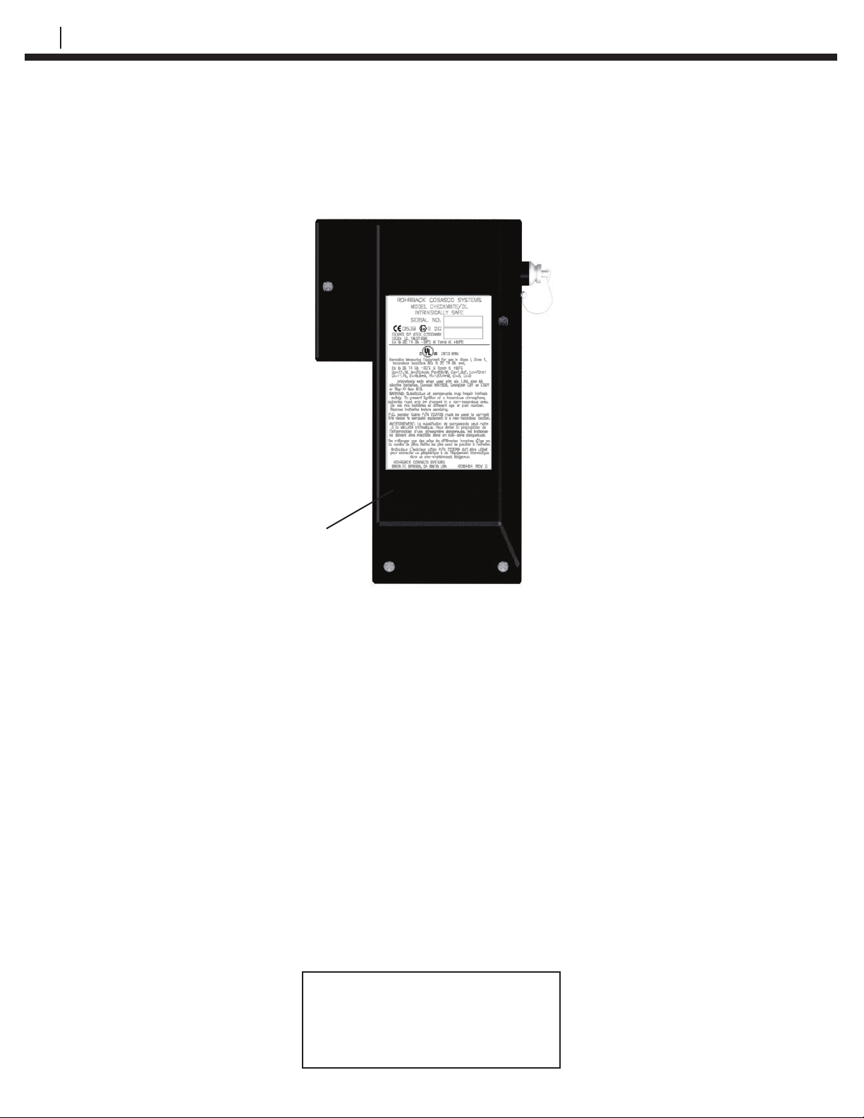
the rear access panel of the unit (see Figure 3.1) with the Allen wrench provided
and install the batteries with the polarities as indicated on the unit.
Page 14
6 BASICS OF CHECKMATE™ DL
Battery Cover
Figure 3.1 Battery Cover of Checkmate DL Instrument
Lithium batteries mounted internally provide alternate power to retain the
confi guration and stored data readings when the primary batteries cease. These
batteries should provide 7-10 years of backup capacity. Replacement of these
batteries requires the unit to be returned to Rohrback Cosasco Systems or an
authorized dealer.
WARNING! Batteries must be changed only in a non-hazardous area.
Checking Battery Status
To check that the unit is operational, press the ON key. The following screen
should appear:
Checkmate DL Ver x.xx
Checking BATTERIES
Please Wait!
Page 15
CHECKMATE™ DL 7
If the batteries are low or in need of replacement, a warning screen will appear
as shown below. Proceed to a safe area and replace the batteries as indicated
on the Battery Installation section.
WARNING!
LOW BATTERIES
REPLACE NOW!
Exit
If the batteries are good, the instrument will proceed to one of the Standby
displays.
Standby Screens of Checkmate DL
The Standby screens are shown below. For Microcor systems, two additional
screens are displayed prior to entering the Standby screen.
ROHRBACK COSASCO SYS
Corrdata
MMM DD, YYYY HH:MM:SS
Read Disp Dump SetUp
If the Checkmate DL is programmed for Microcor Systems, the Checkmate DL
will display the Microcor Free Readings and then the Time Zone screens
shown below.
ROHRBACK COSASCO SYS
Microcor
MMM DD, YYYY HH:MM:SS
Read Conf Data Mate
Available Memory Space and Standard Time Zone
The Microcor Free Readings and the Time Zone screens are shown below.
The fi rst of the two screens displays the remaining available space for data
transferred into the unit.
Microcor
Free Readings xxxxx
Exit
Press Exit (F4) to proceed to the next screen shown below:
Standard Time Zone
|
| UTC +0:00
DTZ Up Down OK
Page 16
8 BASICS OF CHECKMATE™ DL
It is required to set the Time Zone into the Checkmate DL from this screen to
confi gure the Checkmate DL to accurately date and time stamp the readings
acquired from the Data Loggers. Set the Time Zone to either Standard or
Daylight mode on the Checkmate DL by pressing DTZ (F1) to toggle between
Standard and Daylight (the active mode is shown on the top line of the display).
Then use the Up (F2) or Down (F3) buttons to set the UTC offset for the time
zone where the data loggers are located. The correct time zone data is required
because the underlying architecture the Microcor Tools Software is based on
uses a UTC time reference. UTC (GMT) time information is found on computers
in the ‘Date and Time’ settings in Control Panel on Windows Operating Systems.
NOTE: If the clock time on probe readings is incorrect by up to 36
hours, check that the Checkmate DL is set to the correct
time zone. This may be done manually from the “Time Zone”
screen shown above.
Checkmate DL Keypad
The Checkmate DL features a keypad with 34 keys for the alphabet A through
Z and numerals 0 through 9. The numerals are shared with letters F through P
and S. Switch between these letters and numbers using the Alpha/Numeric key.
There are also four soft keys, F1 through F4 (as shown below). The soft keys
are multi-function keys used to make on-screen selections.
F1 F2 F3 F4
Figure 3.2 Checkmate DL Function Keys
Checkmate DL Firmware Version
The Checkmate DL fi rmware version is displayed on the fi rst screen of the
instrument when it is turned on regardless of the data collection system.
Checkmate DL Ver x.xx
Checking BATTERIES
Please Wait!
It is also possible to access the Checkmate DL fi rmware version when it is
programmed for Corrdata Systems. Press the Read (F1) from the Standby
display and select Mode (F2) from the What To Read? display to go to the
Special Test Mode display:
Special Test Mode
Rev. Baud Exit
Page 17
CHECKMATE™ DL 9
Press Rev. (F1) for the revision information display:
Software Revision
Mate = xx.xx
RDC = xx
Exit
If the Checkmate DL is connected to a RDC/ER-210 it will display the fi rmware
version of the RDC along with the fi rmware version of the Checkmate DL.
Standby Display Screens for Microcor and Corrdata Systems
The Checkmate DL handheld instrument can be conveniently switched between
Corrdata and Microcor Systems with only a few keypad entries.
The Standby display screen for the Microcor System and the Corrdata System is shown
below:
ROHRBACK COSASCO SYS
Corrdata
MMM DD, YYYY HH:MM:SS
Read Disp Dump SetUp
ROHRBACK COSASCO SYS
Microcor
MMM DD, YYYY HH:MM:SS
Read Conf Data Mate
Page 18

10 BASICS OF CHECKMATE™ DL
Page 19
Initializing Checkmate DL to
Work with Corrdata System
Confi guring Checkmate DL for Corrdata Systems
If the Checkmate DL is programmed for the Microcor System, it can be easily
changed to the Corrdata System as described below.
WARNING! When switching Checkmate DL between Microcor
and Corrdata Systems, all stored data will be erased!
Be sure to transfer all stored data to the PC prior to
changing the data collection system (see appropriate
chapters for more details on data transfer).
CHECKMATE™ DL 11
CHAPTER 4
From the Standby display, press Mate (F4) then select Mate Type (F3) from
the Mate Functions display. Press Yes (F1) to change the Checkmate DL from
Microcor technology to Corrdata technology.
Setting the Time and Date
The Checkmate DL has its own internal clock so that individual probe readings
are automatically time and date stamped.
To set the internal clock Time and Date, from the Standby display, press SetUp
(F4) then select Mate (F1) from the Confi guration Options display to go to the
Mate Confi guration display:
Press Set Mate (F3) to go to the Mate Settings display:
Mate Confi guration
PC Man Set
Conf Conf Mate Exit
Mate Settings
Set Set Clr
Units Time Mem Exit
Page 20
12 INITIALIZING CHECKMATE™ DL TO WORK WITH CORRDATA SYSTEM
Press Set Time (F2) to go to the Mate Clock display:
Mate Clock Set to
MMM DD, YYYY HH:MM:SS
Read Set Exit
Press Set (F2) to go to the Set Mate Date & Time display:
Set Mate Date and Time
YYMMDDHHMMSS
> <
Enter Clr BkSp Exit
From the keyboard, enter the last two digits of the year followed by the two digit
number of the month, date, the time in hours, minutes and seconds (enter 00
for seconds for convenience). When the time is set correctly, press Enter (F1)
to start the clock. To update the clock on the Mate Clock Set To display, press
Read (F1).
NOTE: The time protocol is based on the military 24 hour clock,
where 00:00 hours denote midnight at the start of the day,
and 12:00 is noon.
Setting the Engineering Units
To set the Engineering Units, from the Standby display, press SetUp (F4) then
select Mate (F1) from the Confi guration Options display to proceed to the Mate
Confi guration display. Press Set Mate (F3) to go to the Mate Settings display
shown below:
Mate Settings
Set Set Clr
Units Time Mem Exit
Press Set Units (F1) to go to the Set Metal Loss Units display:
Set Metal Loss Units
Present Setting
>xxxx<
mils mm um Exit
Select the desired units by pressing mils (F1) for mils (0.001”) and mils/year or
mm (F2) for millimeters and mm/year or um (F3) for micrometers and um/year.
After the selection is made and correctly displayed on the display, press Exit (F4)
to set the units and return to the Mate Settings display.
Page 21
CHECKMATE™ DL 13
Clearing Memory on Checkmate DL
Normally it will not be necessary to clear the memory on the Checkmate
DL unless extraneous entries have been made, for example, when initially
experimenting with the system. However, when the equipment is to be
transferred to a new location, then it is recommended to clear the memory to
avoid confusion with any previously collected data.
NOTE: All data stored in internal memory of the Checkmate DL will
be erased permanently when switching between Microcor
and Corrdata Systems. Make sure to transfer stored data to
the PC prior to changing the data collection system.
To clear the memory, from the Standby display, press SetUp (F4) then
select Mate (F1) from the Confi guration Options display to go to the Mate
Confi guration display and press Set Mate (F3) to go to the Mate Settings
display shown below:
Mate Settings
Set Set Clr
Units Time Mem Exit
Press Clr Mem (F3) and confi rm again on the next screen to clear all memory
stored in the instrument.
Changing the Communication Baud Rate (Function only supported by RDC-COT,
ER-210 and RDC-CAT)
Under normal circumstances, the baud rate will not need to be changed from the
default setting of 9600.
To navigate to the Baud Rate display, press Read (F1) from the Standby screen,
then select Mode (F2) on the What To Read? display to advance to the Special
Test Mode display:
Special Test Mode
Rev. Baud Exit
Press Baud (F2) to modify the baud rate on the following display:
Baud Rate is XXXX
9600 for RDC or PC
300 9600 Exit
Press 300 (F1) or 9600 (F2) to select either the 300 or 9600 baud
respectively. Checkmate DL will set the selected baud rate and return to the
What To Read? display.
Page 22

14 INITIALIZING CHECKMATE™ DL TO WORK WITH CORRDATA SYSTEM
Page 23
Confi guring Checkmate DL
with RDC/ER-210 Confi guration
Import RDC/ER-210 Confi gurations to Checkmate DL using a PC and
Corrdata Plus
Create the desired Site, Group and Probe list running the Corrdata Plus
software program on the PC. To confi gure the Checkmate DL with the above
created probe list; click the Device Confi guration command button on the
Corrdata Plus software program. Choose the Mate radio button on the Select
Device area and select Checkmate from the Select Method drop down menu.
Now, select a complete group or an individual probe from the list to confi gure the
Checkmate DL.
CHECKMATE™ DL 15
CHAPTER 5
Connect the Checkmate DL to the PC (ensure the correct port number is
selected).
Power the Checkmate DL and from the Standby display, press SetUp (F4) then
select Mate (F1) from the Confi guration Options display to proceed to the Mate
Confi guration display:
Press PC Conf (F1) to enter the following screen:
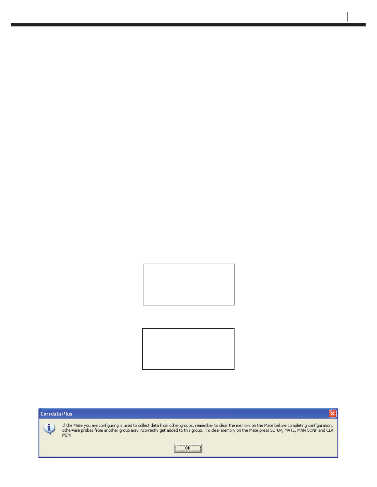
Click the Confi gure Device command button on the Corrdata Plus software
program. The following dialogue box may appear:
Mate Confi guration
PC Man Set
Conf Conf Mate Exit
Connect Mate to PC
PC must be running
Corrdata Plus
Start Exit
Page 24
16 CONFIGURING CHECKMATE™ DL WITH RDC CONFIGURATION
Select OK. The following dialogue box will appear:
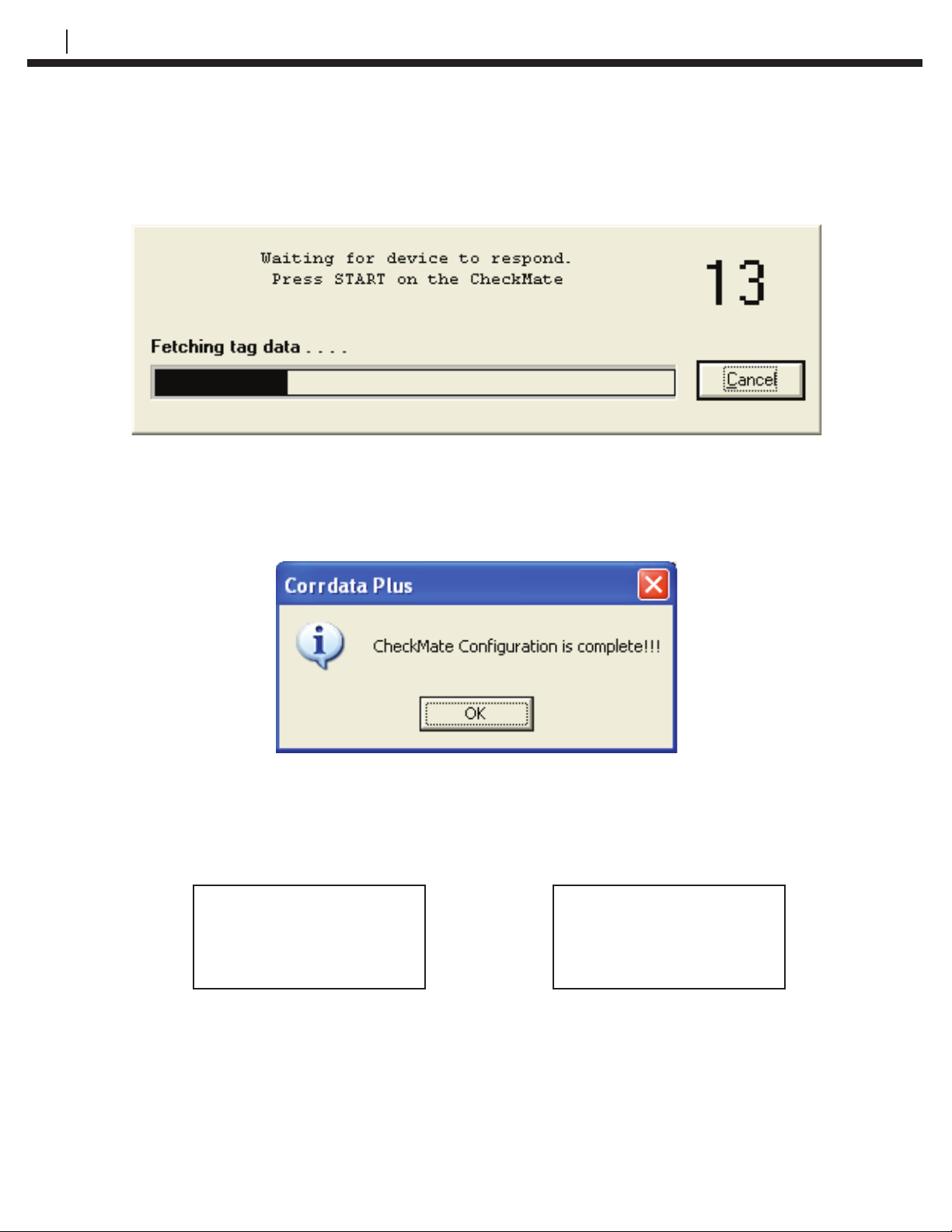
Press the Start (F1) on the Checkmate DL. Successful confi guration will
generate “Checkmate Confi guration is complete!!!” message on the PC
as shown below and the Checkmate will automatically return to the Mate
Confi guration display:
If following error messages appear on the Checkmate DL, ensure the Checkmate
DL is properly connected to the PC and verify the port number is correct. Be sure
that the baud rate on both the computer and the Checkmate DL are set to 9600
baud.
WARNING!
No Response From RDC
Check Connection
Exit
Exit
WARNING!
Error While Getting
Data
Manually Set RDC/ER-210 Confi gurations to Checkmate DL
This section explains the procedure to manually confi gure the Checkmate DL
with the confi guration information of Corrosometer or Corrater probes attached
to a RDC/ER-210. Once the RDC/ER-210 information is properly confi gured in
the Checkmate DL, RDC/ER-210 units will need to be programmed. Refer to
the Confi guring a RDC/ER-210 Using the Checkmate DL chapter for more
information.
Page 25
CHECKMATE™ DL 17
From the Standby display, press SetUp (F4) then select Mate (F1) from the
Confi guration Options display to proceed to the Mate Confi guration display:
Mate Confi guration
PC Man Set
Conf Conf Mate Exit
Press Man Conf (F2) to proceed to the Enter Probe ID display:
Enter Probe ID
Enter ID >***< 1-50
Enter Clr BkSp Exit
Enter a number from 1 to 50 and press Enter (F1) to go to the Enter
Probe Tag display. If an invalid ID is entered, it is automatically cleared
upon pressing Enter (F1), enter a valid ID and retry. If the ID selected
has already been confi gured, the This ID Already Confi gured display
appears:
This ID Already
Confi gured
Try
Cont Again Exit
Pressing Exit (F4) returns the instrument to the Confi guration Options
display. Press Try Again (F2) to return to the Enter Probe ID display or
Cont (F1) to continue to the Enter Probe Tag display and reconfi gure the
ID:
Enter Probe Tag
> <
Enter Clr BkSp Exit
In the Enter Probe Tag display, enter up to twelve (12) alpha/numeric
characters to uniquely identify the monitoring location. This can be a tag
number, location or process name. Pressing Clr (F2) clears a previously
entered ID. Pressing BkSp (F3) backs up one space for each time it is
pressed so that a change can be made. Pressing Exit (F4) returns to the
Confi guration Options display.
Press Enter (F1) to go to the Select Probe Type display:
Select Probe Type
> <
SCROLL
Enter Up Down Exit
Page 26
18 CONFIGURING CHECKMATE™ DL WITH RDC CONFIGURATION
The available probe type selections are W80 WIRE, W65 WIRE, W45 WIRE,
W40 WIRE, TF50, TF5, T50 CYLINDRICAL, T20 CYLINDRICAL, T10
CYLINDRICAL, T8 TUBE LOOP, T4 TUBE LOOP, S50 FLUSH, S40 FLUSH,
S20 FLUSH, S10 FLUSH, S8 STRIP LOOP, S8 FLUSH, S4 STRIP LOOP, S4
FLUSH, S4 ATMOSPHERIC, CORRATER, CORRATER FLUSH, OTHER and
TEST PROBE CO.
NOTE: See more details on selecting “OTHER” probes towards the end
of this section.
It is possible to scroll up through the list by repeatedly pressing the Up (F2)
key or down through the list by repeatedly pressing the Down (F3) key. When
the desired probe element is displayed, press the Enter (F1) key to accept the
selection.
If a TF5 or TF50 high sensitivity atmospheric CORROSOMETER
probe has been selected, the Checkmate DL will go to a special
Enter Probe Span display:
Enter Probe Span
> < Angstroms
Enter Clr BkSp Exit
Using the numeric portion of the keypad, enter the probe
span in Angstroms (Ǻ). The packaging for the TF5 and TF50
CORROSOMETER provides the specifi c span for the probe. If the
specifi c span data is not available, the nominal span can be used
without appreciable error.
If a Corrater or Corrater Flush probe has been selected, the
Checkmate DL will proceed to a special Select Probe Alloy
display:
Select Probe Alloy
> , <
> <
Enter Up Down Exit
Page 27
CHECKMATE™ DL 19
It is possible to scroll up through the list by repeatedly pressing the Up (F2)
key or down through the list by repeatedly pressing the Down (F3) key. When
the desired probe element is displayed, press the Enter (F1) key to accept the
selection.
Select OTHER (see below) if no default selection applies to the
probe being used.
Select Probe Alloy
> OTHER <
>OTHER<
Enter Up Down Exit
Pressing the Enter (F1) key will advance the display to the Enter
Probe Alloy display:
Enter Probe Alloy
> <
Enter Clr BkSp Exit
The Enter Probe Alloy display allows the user to enter up to
eight (8) alpha/numeric characters to identify the alloy of the
probe element for reference purposes only. It does not affect the
corrosion rate calculation.
Press Enter (F1) again to go to the Enter Alloy Mult display:
Enter Alloy Mult
> <
Enter Clr BkSp Exit
Enter the Alloy Multiplier for the probe. Refer to Table 5.2 Alloy
Multipliers for more details.
If a CORROSOMETER probe (element) is selected, the above steps are
bypassed and the Checkmate DL will automatically proceed to the Enter Probe
Alloy display:
Enter Probe Alloy
> <
Enter Clr BkSp Exit
Page 28
20 CONFIGURING CHECKMATE™ DL WITH RDC CONFIGURATION
The Enter Probe Alloy display allows the user to enter up to
eight (8) alpha/numeric characters to identify the alloy of the
probe element for reference purposes only. It does not affect the
calculation of corrosion rates.
Press the Enter (F1) key to advance to the next display shown below:
Is This A Corrotemp
Probe?
Yes No
Make the appropriate selection, Checkmate DL will proceed to the next display:
RDC Time Interval
( 1 - 24 ) > < Hours
Enter Clr Mins Exit
Key in the desired read time interval for RDC/ER-210 readings (default selection
is presented in hours) and press Enter (F1). Pressing the Enter (F1) without
specifying a value will default the read interval to One (1) hour. Press the Mins
(F3) key to change the time interval selection to minutes (shown below):
RDC Time Interval
( 5 - 30 ) > < Mins
Enter Clr Hrs Exit
Key in the desired minute read interval and press the Enter (F1) key to advance
to the next display. Pressing the Enter (F1) without specifying a value will default
the read interval to fi ve (5) minutes. The minimum read time interval for a Four
(4) Channel RDC is 15 minutes. Although Corrosometer probes attached to RDC
– COT/ER-210 may be set up to have a 5 minute read time interval, 4 Channel
RDC will change the read time to 15 minutes (RDC–COT/ER-210 (one channel)
will retain the 5 minute read interval).
The minimum read time interval offered for Corrater and Corrater Flush probe
is 30 minutes. In this case, choosing Mins (F3) will show the following display.
Press OK (F1) to accept, Hrs (F3) to return to hourly RDC/ER-210 Time Interval
display, or Exit (F4) to exit to Confi guration Options screen:
RDC Time Interval
Set to 30 Mins
OK Hrs Exit
Page 29
CHECKMATE™ DL 21
Once the appropriate selections are made, the following display will appear
indicating the Checkmate DL was successfully confi gured. Press the Exit (F4)
key to return to the Standby screen:
Mate Confi gured for
ID: xxx xxxxxxxxx
Exit
If OTHER is selected from the probe type selections on the Select Probe Type
display, the Checkmate DL will proceed to the Enter Probe Type display shown
below:
Enter Probe Type > <
(A thru G)
Type
Enter Clr List Exit
Enter A for Wire Loop type probes or enter B or C for Tube Loop/Strip Loop
type probes or enter D for Cylindrical type probes or E for Corrater probes or
F for Corrater Flush probes or G for High Sensitive Probes. If you are unsure
of the element type, this information can be found on the probe packaging,
etched on the probe body adjacent to the connector or in Table 5.1 Probe Type
Identifi cation.
Make the Probe Type selection and press Enter (F1). Following Enter Probe
Span display will appear if type A, B, C, or D is selected:
Enter Probe Span
> < mils
Enter Clear BkSp Exit
From the keypad, enter the span of the probe element in mils. The span in mils
is shown on the probe packaging or it can be found in Table 5.1.
If Type G for the Model 610 Atmospheric Probes is selected, the span is entered
in Angstroms, see the following Enter Probe Span display:
Enter Probe Span
> < Angstroms
Enter Clear BkSp Exit
Page 30
22 CONFIGURING CHECKMATE™ DL WITH RDC CONFIGURATION
Once the span is entered, press the Enter (F1) key to proceed to the Enter
Probe Alloy display:
Enter Probe Alloy
> <
Enter Clr BkSp Exit
The Enter Probe Alloy display allows the user to enter up to eight (8) alpha
or numeric characters to identify the alloy of the probe element for reference
purposes only. It does not affect the calculation of corrosion rates. At this point,
the Checkmate DL will proceed to the Is This A Corrotemp Probe? display.
Make the appropriate selection, Yes (F1) or No (F4). Checkmate will proceed
to the RDC Time Interval display; make the appropriate selection to advance
to the next screen. Checkmate DL will automatically proceed to conclude
the confi guration process. Scroll up in this section (Manually Confi guring a
Corrosometer or Corrater Probe attached to a RDC/ER-210) for step by step
illustrated descriptions.
If type E or F is selected, following Select Probe Alloy display will appear:
Select Probe Alloy
> , <
> <
Enter Up Down Exit
Scroll up or down through the list by repeatedly pressing the Up (F2) key or the
Down (F3) key. When the desired probe element selection is displayed, press
the Enter (F1) key to accept the selection. Next screen (Is This A Corrotemp
Probe?) will prompt to choose Yes (F1) or No (F4). Make the appropriate
selection. Checkmate DL will proceed to the RDC Time Interval display; make
the appropriate selection to advance to the next screen. Checkmate DL will
automatically proceed to conclude the confi guration process. Scroll up in this
section (Manually Confi guring a Corrosometer or Corrater Probe attached to
a RDC/ER-210) for step by step illustrated descriptions.
If OTHER is selected in the Select Probe Alloy display as shown
below, pressing the Enter (F1) key will advance the display to
the Enter Probe Alloy screen. The Enter Probe Alloy display
allows the user to enter up to eight (8) alpha/numeric characters
to identify the alloy of the probe element for reference purposes
only. It does not affect the calculation of corrosion rates. Press
Enter (F1) again, follow the prompts and enter the necessary
values to conclude the confi guration process. Scroll up in this
section (Manually Confi guring a Corrosometer or Corrater
Probe attached to a RDC/ER-210) for step by step illustrated
descriptions.
Select Probe Alloy
> OTHER <
>OTHER<
Enter Up Down Exit
Page 31
CHECKMATE™ DL 23
Checkmate DL is successfully confi gured when the following display appears:
Mate Confi gured for
ID: xxx xxxxxxxxx
Exit
Press Exit (F4) to return to the Standby screen.
CORROSOMETER or CORROTEMP
Probe Element
Strip Loop S4 C 1
Flush Element S4
Atmospheric Element S4
Strip Loop S8
Tube Loop T4
Flush Element S8
Atmospheric Element S8
Tube Loop T8
Flush Element S10
Cylindrical Element T10
Flush Element S20
Cylindrical Element T20
Wire Loop Element W40
Wire Loop Element W45
Flush Element S20
Wire Loop Element W80
Type Span
(mils)
B
D
C
B
B
D
B
B
D
B
D
A
A 11,15
B
A
10
20
2
4
5
Cylindrical Element T50
D25
Table 5.1 CORROSOMETER and CORROTEMP Probe Types and Spans
Note: CORROSOMETER Model 2500, 3500, or 4500 probes are
designated as a “cylindrical” element, not as “tube” element which
refers only to “tube loop” elements.
Page 32
24 CONFIGURING CHECKMATE™ DL WITH RDC CONFIGURATION
UNS Code Material Multiplier
K03005 Pipe Grade Carbon Steel 1.00
A91100 Aluminum 1100-0 0.94
A92024 Aluminum 2024 0.88
C11000 Copper 110 ETP Comm. Pure 2.00
C44300 CDA 443 Arsenical Admiralty 1.67
C44500 CDA 445 Phosphorized Adm. 1.68
C64200 CDA 642 A1 Silicon Bronze 1.48
C68700 CDA 687 Alum. Brass Arsenical 1.62
C70610 CDA 706 90/10 Copper/Nickel 1.80
C71500 CDA 715 70/30 Copper/Nickel 1.50
G41300 AISI 4130 Alloy Steel 1.00
L50045 Lead 2.57
N04400 Monel 400 Nickel 1.13
N05500 Monel K-500 Nickel 1.04
N06022 Hastelloy C22 0.85
N06600 Inconel 600 Nickel 0.95
N08020 Carpenter 20 CB3 SST 0.98
N08800 Incolloy 800 0.89
N08825 Incolloy 825 0.88
N10276 Hastelloy C276 0.86
R50400 ASTM B-348 Grades 2-4 Titanium 0.75
S30400 AISI 304 Stainless Steel 0.89
S31600 AISI 316 Stainless Steel 0.90
S31603 AISI 316L Stainless Steel 0.90
S31803 2205 Duplex Stainless Steel 0.89
S32750 2507 Duplex Stainless Steel 0.88
Z17001 Grades 1A, 1, 2, 3, or 5 Zinc 1.29
Note: These factors are
recommended for the
MULTIPLIER values. They are
based on use of CORRATER
electrodes which have surface
areas of 5cm2 for “standard”
probes and 0.5 cm2 for “fl ush”
probes.
Table 5.2 Alloy Multipliers
Page 33
Confi guring a RDC/ER-210
Using Checkmate DL
Setting the Date and Time on RDC/ER-210s (RDC-COT/ER-210, RDC-CAT
only)
From the Standby display, press SetUp (F4) then select RDC (F2) from the
Confi guration Options display to proceed to the RDC Confi guration display:
Connect Mate To RDC
Date Conf Test
Time RDC Mode Exit
CHECKMATE™ DL 25
CHAPTER 6
RDC Confi guration
Press Date Time (F1) and the following screen will appear:
RDC Clock Set To
mm dd, yyyy hh:mm:ss
Read Set Exit
Press Set (F2). The RDC Clock Set To display will change to show:
RDC Clock Set To
SETTING RDC CLOCK
Read Set Exit
The RDC/ER-210 internal clock will be synchronized with the Checkmate DL
clock. Press Read (F1) to verify the time of the RDC. Press the Exit (F4) to
return to the RDC Confi guration display.
If the following message appears, check to ensure the validity of the connection.
WARNING!
No Response From RDC
Check Connection
Exit
Page 34
26 CONFIGURING A RDC USING CHECKMATE™ DL
Confi gure a RDC/ER-210 using the Checkmate DL
Checkmate DL is designed to confi gure and gather data from all RDC/ER-210s.
Refer to Reading a Remote Data Collector (RDC)/ER-210 section for more
details on reading RDC/ER-210s. This section will explain the confi guration
procedure of a RDC/ER-210 from a Checkmate DL.
To begin the confi guration process, connect the Checkmate DL to the RDC/ER-
210s with the provided LEMO connector. Power-on the Checkmate DL. Press
SetUp (F4) from the Standby display and then select RDC/ER-210 (F2) from the
Confi guration Options display to proceed to the RDC/ER-210 Confi guration
display:
RDC Confi guration
Connect Mate To RDC
Date Conf Test
Time RDC Mode Exit
Press the Conf RDC (F2) to proceed to the following screen:
Enter ID# > < 1 - 50
Enter Clr BkSp Exit
Enter the ID number (1 – 50) using the numeric keys of the Checkmate DL.
In order to confi gure the RDC, the probe must be already programmed in
the Checkmate DL. Refer to the Manually Confi guring a Corrosometer or
Corrater Probe attached to a RDC/ER-210 section or Probe Confi guration
using a PC and Corrdata Plus Software section in the Probe Confi guration
chapter for more details.
If the probe is not properly confi gured in the Checkmate DL before
confi guring the RDC/Er-210, the following error message will
display:
WARNING!
Mate Not Confi gured
For This ID
Exit
Press Exit (F4) once to enter the RDC/ER-210 Confi guration
display and press the Conf RDC (F2) to enter a different ID. If it is
desirable to confi gure the above ID, press Exit (F4) continuously
to return to the Standby display and confi gure the ID by
navigating to the appropriate displays, and try again.
If the connection between the RDC/ER-210 and the Checkmate
DL is interrupted or invalid, the following display will appear:
Page 35
WARNING!
No Response From RDC
Check Connection
Exit
Press the Exit (F4) key to return to the Confi guration Options
display. Select RDC (F2) to go to the RDC Confi guration display
and repeat the above process with the connection properly
established.
If either of the following error messages appears, verify the
Probe Type confi gured for the RDC/ER-210. RDC – CO
(Corrosometer) and RDC – CA (Corrater) technologies require
different probe confi gurations. Refer to the Manually Confi guring
a Corrosometer or Corrater Probe attached to a RDC/ER-210
section or Probe Confi guration using a PC and Corrdata Plus
Software section in the Probe Confi guration chapter for more
details.
CHECKMATE™ DL 27
Upon successful entry of the ID, the following RDC Confi guration display will
appear:
Press Start (F1) to confi gure the RDC/ER-210.
If the connection between the RDC/ER210 and the Checkmate DL
is interrupted, the following display will appear:
WARNING!
Mate Not Connected
To RDC - CO
Exit
RDC Confi guration
Set New
Start Mux Probe Exit
WARNING!
No Response From RDC
Check Connection
Exit
WARNING!
Mate Not Connected
To RDC - CA
Exit
Verify the connection by checking the LEMO connector cable
between the Checkmate DL and the RDC/ER-210. Press Exit (F4)
and retry.
If the RDC/ER-210 was previously programmed, Checkmate DL
will proceed to the following display:
Page 36
28 CONFIGURING A RDC/ER-210 USING CHECKMATE™ DL
This RDC Already
Confi gured As ID# xx
Cont Exit
If replacing the existing ID with the new confi guration is desired, press Cont (F1)
(see display below), otherwise Exit (F1) to return to the RDC Confi guration
display to begin confi guration of a different ID:
RDC # xx
Confi gured
Exit
Press Exit (F4) to return to the Confi guration Options display.
For Four (4) Channel RDC units, each probe confi guration (channel) must be
individually confi gured. Follow the procedure above to confi gure the fi rst channel.
At the completion of the above procedure, the Checkmate DL should be at the
Confi guration Options display. Now, press RDC (F2) to proceed to the RDC
Confi guration display and repeat the procedure to confi gure the remaining
channels. Also refer to the Confi guration of 4 Channel RDC section below. The
minimum read time interval for a Four (4) Channel RDC is 15 minutes. Although
Corrosometer probes attached to RDC – COT may be set up to have a 5 minute
read time interval, 4 Channel RDC will change the read time to 15 minutes (RDC
– COT (one channel) will retain the 5 minute read interval).
NOTE: RDC units will not collect data while the Checkmate DL is
connected. Make sure to unplug the Checkmate DL from the RDC
to begin data collection cycle.
Updating RDC/ER-210 Confi guration upon Probe Replacement
The initial Check reading can be reset easily on the RDC/ER-210 when a
probe is replaced. The Check reading is a measure of probe functionality or
integrity. The initial value for CORROSOMETER probes is 800 ±50 divisions. It
is recommended that a Check reading be taken and recorded immediately after
unpacking a probe as it will be the value to which all subsequent Check readings
will be compared. The general rule is that the Check reading should not vary by
more than 1% (±10 divisions) from the initial value. A change greater than 1%
indicates a compromise in the probe integrity and replacement is required.
To reset the Initial Check reading, connect the Checkmate DL to the RDC/ER210 with the provided LEMO connector cable and power up the Checkmate DL.
Press SetUp (F4) from the Standby display and then select RDC (F2) from the
Confi guration Options display to proceed to the RDC Confi guration display:
Page 37
CHECKMATE™ DL 29
RDC Confi guration
Connect Mate To RDC
Date Conf Test
Time RDC Mode Exit
Press the Conf RDC (F2) to proceed to the following screen:
Enter ID# > < 1 - 50
Enter Clr BkSp Exit
Enter the ID number (1 – 50) using the numeric keys of the Checkmate DL. Press
the Enter (F1) key.
NOTE: Refer to the “Confi gure a RDC/ER-210 Using the Checkmate DL”
section above for any Warning and/or Error messages.
Press New Probe (F3) to reset the Initial Check reading on the following display:
RDC Confi guration
Set New
Start Mux Probe Exit
Checkmate DL will return to the following display after resetting the Check value:
RDC Confi guration
Connect Mate To RDC
Date Conf Test
Time RDC Mode Exit
Confi guration of 4 Channel RDC
When initially confi guring the 4 Channel RDC, it will begin at channel 1 and
proceeds through to channel 4, and then wrap around to channel 1 again. This
may not be suitable when less than four channels are to be confi gured, or when
one or more channels are to be reconfi gured. The Checkmate DL allows users to
select any one of the channels on the 4 Channel RDC and also allows switching
ON or OFF of any of the channels without losing the confi guration information.
WARNING! When re-confi guring any channel, previously saved data
on all the other channels will be erased and a new data
collection run commenced. Therefore all the data from the
other channels MUST be collected BEFORE any channel is
reconfi gured to AVOID LOSS OF DATA.
Page 38
30 CONFIGURING A RDC/ER-210 USING CHECKMATE™ DL
To select, deselect or set as active a channel, connect the Checkmate DL
to the RDC/ER-210 with the provided LEMO connector cable and power up
the Checkmate DL. Press SetUp (F4) from the Standby display and then
select RDC (F2) from the Confi guration Options display to go to the RDC
Confi guration display:
RDC Confi guration
Connect Mate To RDC
Date Conf Test
Time RDC Mode Exit
Press the Conf RDC (F2) and the following screen will appear:
Enter ID# > < 1 - 50
Enter Clr BkSp Exit
Enter the ID number (1 – 50) using the numeric keys of the Checkmate DL.
Press the Enter (F1) key.
NOTE: Refer to the “Confi gure a RDC/ER-210 Using the Checkmate DL”
section above for any Warning and/or Error messages.
Press Set MUX (F3) on the following display:
RDC Confi guration
Set New
Start Mux Probe Exit
This will advance the Checkmate DL to the following display:
Mux Chan x < xxx >
ID: xx xxxxxxxxxxx
ON SEL Next Exit
The fi rst line shows the selected channel and its status inside the < > symbols.
The ON (F1) key is a multifunctional key that alternates back and forth with OFF
(F1). Selecting ON (F1) on channel 1 and pressing the SEL (F2) will depict the
following display:
Mux Chan 1 <ON-SEL >
ID: xx xxxxxxxxxxx
OFF Next Exit
Page 39

CHECKMATE™ DL 31
Channel 1 is switched ON and is currently SELECTED to transmit data or
receive any instructions from the Checkmate DL. Press OFF (F1) to suspend
the data collection from this channel if desired. If this channel is not currently
SELECTED, only “ON” will appear in the status area (channel is active, but not
selected to receive instructions or transmit data). Pressing Next (F3) will advance
the Checkmate DL to the next channel. It is possible now to make changes to this
channel using the F1 and/or F2 keys. Next (F3) key will proceed through to the
next channel and wrap around to the fi rst channel.
Press the Exit (F4) button to return to the RDC Confi guration display.
Page 40

32 CONFIGURING A RDC/ER-210 USING CHECKMATE™ DL
Page 41
CHECKMATE™ DL 33
Reading a RDC/ER-210 with the
Checkmate DL
The Checkmate DL is designed to confi gure and gather data from all RDC/ER-
210s. Refer to Confi gure a RDC/ER-210 using the Checkmate DL section for
more details on confi guring RDC/ER-210s. The following section will explain the
RDC/ER-210 data collection procedure.
Data Collection from a RDC/ER-210
To read a RDC/ER-210, connect the Checkmate DL to the RDC/ER-210 with the
LEMO connector cable. From the Standby screen, press Read (F1) to proceed
to the What To Read? display:
What To Read?
Mode RDC Exit
Press RDC (F3) to proceed to the Connect Mate To RDC display:
Connect Mate To RDC
CHAPTER 7
Start Exit
Press Start (F1) to begin reading data from the RDC/ER-210. When the data
collection is successfully completed, the Checkmate DL will advance to the
display shown below:
Data Collected From
ID: xxx xxxxxxxxxx
Exit
For Four (4) Channel RDC units, four readings must be taken to collect the data
from the four attached probes. From the Connect Mate To RDC display press
Start (F1) to read the fi rst probe. Once that is successfully completed, press
the Exit (F4) from the Data Collected From display to advance to the Connect
Mate To RDC. Press Start (F1) and repeat to collect data from the remaining 3
probes.
Unsuccessful data read attempts will cause the unit to display any of the
following error messages:
Page 42
34 READING A RDC/ER-210 WITH THE CHECKMATE™ DL
Error Downloading
Exit
Verify the RDC/ER-210 is properly confi gured. Inspect the data cable for proper
connection to the RDC/ER-210 and the Checkmate DL. Replace the RDC/ER210 battery if required. Try again.
WARNING!
RDC Not Confi gured
Exit
No Response From RDC
WARNING!
Check Connection
Exit
Reading the RDC Confi guration Details
From the Standby display, press SetUp (F4) then select RDC (F2) from the
Confi guration Options display to proceed to the RDC Confi guration display:
RDC Confi guration
Connect Mate To RDC
Date Conf Test
Time RDC Mode Exit
Press Test Mode (F3) to enter the following RDC Test Mode display:
RDC Test Mode
Read
Test Read Read
Probe Conf Time Exit
Press Read Conf (F2) key to enter the following display with the confi guration
details:
ID: xx xxxxxxxxxxxxx
Type: xxxxxxxxxxxx
Alloy: xxxxxxxxxxx
Exit
The ID: line displays the ID number assigned to the RDC/ER-210 and the Probe
Tag. The Type: line displays the Probe Type. Press More (F4) to advance to the
following screen:
Interval: xxx
Num Readings: xx
Next Read: hh:mm:ss
Exit
The Interval: line displays the probe read time interval in minutes or hours as
confi gured. The Num Readings: line displays the number of readings taken
thus far by the RDC/ER-210 with the current confi guration. The Next Read: line
Page 43
CHECKMATE™ DL 35
displays the time when the next data collection cycle will begin.
Press Exit (F4) once to return to the RDC Test Mode display or continuously to
return to the Standby display.
If the following message appears, check the connection between the Checkmate
DL and the LEMO connector cable. Pressing Exit (F4) will return the Checkmate
DL to the Confi guration Options display, select RDC (F2) to advance to the
next display. Press Test Mode (F3) to re-enter the RDC Test Mode display and
retry.
WARNING!
No Response From RDC
Check Connection
Exit
Reading the Programmed Date and Time on the RDC/ER-210
From the Standby display, press SetUp (F4) ant then select RDC (F2) from the
Confi guration Options display to proceed to the RDC Confi guration display:
RDC Confi guration
Connect Mate To RDC
Date Conf Test
Time RDC Mode Exit
Press Test Mode (F3) to enter the following RDC Test Mode display:
RDC Test Mode
Read
Test Read Read
Probe Conf Time Exit
Press Read Time (F3) key to enter the following display with the Date and Time
details:
Cur Date: mmm dd, 20yy
Cur Time: hh:mm:ss
Lst Read: mmm dd, 20yy
At: hh:mm:ss Exit
The Cur Date: line displays the current date while the Cur Time: displays the
time in military 24 hour time, where 00:00 hours denotes midnight at the start of
the day, and 12:00 is noon. Lst Read: line displays the date of the last reading
performed while At: displays the time of that reading.
Press Exit (F4) once to return to the RDC Test Mode display or continuously to
return to the Standby display.
Page 44
36 READING A RDC/ER-210 WITH THE CHECKMATE™ DL
If the following message appears, check the LEMO cable connection. Pressing
Exit (F4) will return the Checkmate DL to the Confi guration Options display,
select RDC (F2) to advance to the next display. Press Test Mode (F3) to enter
the RDC Test Mode display and retry.
WARNING!
No Response From RDC
Check Connection
Exit
Perform a “Test Read” on a RDC/ER-210 (Function only supported by RDC-
COT, ER-210 and RDC-CAT)
It is possible to perform a test reading on a RDC/ER-210 from a Checkmate
DL to verify the proper setup of the RDC/ER-210 and the validity of the cable
connectivity in the fi eld. In order for this test reading, a test probe or special
probe is required.
From the Standby display of the Checkmate DL, press SetUp (F4) and then
select RDC (F2) from the Confi guration Options display to go to the RDC
Confi guration display:
RDC Confi guration
Connect Mate To RDC
Date Conf Test
Time RDC Mode Exit
Press Test Mode (F3) to enter the following RDC Test Mode display:
RDC Test Mode
Read
Test Read Read
Probe Conf Time Exit
Press Read Test Probe (F1) key to enter the following display:
Test Mode Menu
Start Read Exit
A test probe must be attached to the RDC/ER-210 before pressing Start (F1).
Pressing Start (F1) will advance the Checkmate DL to the following display:
RDC Is Now Reading
Test Probe. This Will
Take Approx. 4 min.
Exit
Press the Exit (F4) to return to the Test Mode Menu.
Page 45
CHECKMATE™ DL 37
The reading is being performed. Do not press Start (F1) again or Read
(F3) before the reading is complete or a No Response From RDC - Check
Connection warning message will display. See below for details on navigating
back to the Test Mode Menu after getting the warning message display.
NOTE: It will take up to 4 minutes to successfully complete the reading.
The Checkmate DL will power off after 2 minutes if left idle after
reading. This is normal behavior of the equipment. The reading
will still commence on the RDC/ER-210.
Display the “Test Read” Results
When adequate time has passed, the test reading result may be viewed by
pressing the following sequence of buttons. From the Standby display press
SetUp (F4), then select RDC (F2) from the Confi guration Options display to
proceed to the RDC Confi guration display. Select Test Mode (F3) to advance to
the RDC Test Mode screen. Press the Read Test Probe (F1) to proceed to the
Test Mode Menu; press Read (F3) to advance to one of the following displays.
If the unit is a RDC–COT/ER-210 or a 4 Channel RDC – COT, the
following display will appear:
Test Probe Readings
Div: xxx.x
Check: xxx
Exit
If the unit is a RDC – CAT, the following display will appear:
Test Probe Readings
Rate: xxx
Imb: xxx
Exit
If the following warning appears, check connection integrity. Pressing Exit (F4)
will return the Checkmate DL to the Confi guration Options display, select RDC
(F2) to advance to the next display. Press Test Mode (F3) to enter the RDC Test
Mode display and press Read Test Probe (F1) to return to the Test Mode Menu.
WARNING!
No Response From RDC
Check Connection
Exit
Page 46

38 READING A RDC/ER-210 WITH THE CHECKMATE™ DL
Page 47
Displaying RDC/ER-210 Data
on the Checkmate DL
Probe reading data stored on RDC/ER-210 can be transferred to the PC using
Corrdata Plus or the latest reading may be displayed on the Checkmate DL for
user convenience. For Corrosometer probes data includes the Tag ID, Metal
Loss, Corrosion Rate, Divisions and Check Readings, Alloy, Span, Temperature
(where applicable), number of Readings, and Interval. For Corrater probes
data includes Tag ID, Corrosion Rate, Imbalance, Temperature, Alloy, Multiplier,
number of Readings, and reading Interval.
CHECKMATE™ DL 39
CHAPTER 8
From the Standby screen, press Disp (F2) to proceed to the Display Data By
display:
Display Data By
Curr
Probe ID Exit
Press Curr Probe (F1) to see the last viewed probe ID or press ID (F2) to select
the probe by ID.
If a Corrosometer probe is attached to the RDC/ER-210, following display will
appear:
ID: xxx xxxxxxxxxxxxx
Div: xxx Chk: xxx (xxx)
Temp: xxx C xx F xx
More Exit
Press More (F1) to proceed to the next display:
Alloy: xxxxxxxxx
Span: xxxx
xxxx Readings @ xxint
Exit
If a Corrater probe is attached to the RDC/ER-210, following display will appear:
ID: xxx xxxxxxxxxxxxx
Rate: xxx units
Imb: xxx Temp: xxx C
More Exit
Page 48
40 DISPLAYING RDC/ER-210 DATA ON THE CHECKMATE™ DL
Press More (F1) to proceed to the next display:
Alloy: xxxxxxxxx
Mult: xxxxx
xxxx Readings @ xxint
Exit
Page 49
Transferring RDC/ER-210
Data to the PC
Probe reading data is uploaded to the PC using the provided Corrdata Plus
Corrosion Management Software program. This is a Windows compatible
program that allows fast uploading of data stored in the Checkmate DL.
Corrdata Plus Installation
The Corrdata Plus Corrosion Management Software program can be found on
the USB Drive included with the instrument. Insert the USB Drive and follow the
on-screen instructions to install. The default installation directory is C:\Program
Files\RCS\Corrdata Plus.
CHECKMATE™ DL 41
CHAPTER 9
Confi guring Corrdata Plus
When the installation is complete, launch the Corrdata Plus program from
All Programs
the Corrdata Plus User Manual provided on the USB Drive for site setup and
confi guration.
----
> Rohrback Cosasco Systems. Follow the instructions on
Connecting the Checkmate DL to the PC
Connect the Checkmate DL to the 9 pin serial port on the PC using the provided
cable. Verify the correct COM port number is selected on the Corrdata Plus
Corrosion Management Software program (in most cases this will be COM
1, however verify this in the device manager). If there is no serial port in the
computer, use the included serial-to-USB converter cable to complete the
connection.
Launch and Open an Existing Site or Create a New Site on the Corrdata Plus
Corrosion Management Software program. Ensure the correct port number is
selected on Preferences
----
> Settings
----
> Default Port: section.
Checkmate DL Data Transfer Procedure
From the Standby screen, press Dump (F3) to proceed to the following display:
Connect Mate To PC
PC Must Be Running
Corrdata Software
Start Exit
Page 50
42 TRANSFERRING RDC/ER-210 DATA TO THE PC
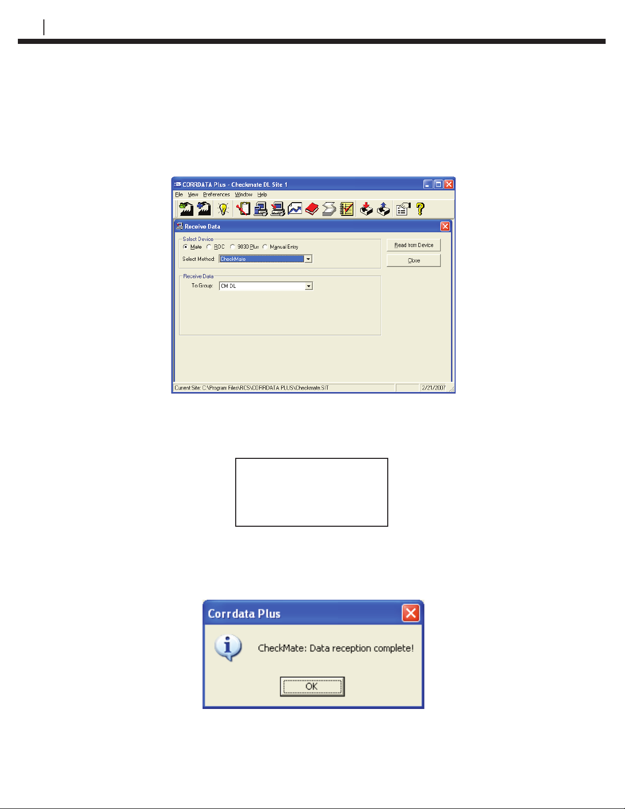
On the Corrdata Plus Corrosion Management Software program, click the
Receive Data command button, select Mate as the Select Device, and
Checkmate as the Select Method. Choose the appropriate To Group selection.
Click the Read from Device command button on the screen shown below:
Press Start (F1) on the Checkmate DL to begin uploading data to the PC.
Checkmate DL will show the following screen:
Dumping Data to PC
Please Wait
ID: xxx xxxxxxxxxxx
Once the data is successfully transferred, Checkmate DL will return to the
Standby display screen and Corrdata Plus Corrosion Management Software will
show the following dialogue box:
If the Checkmate DL is not connected to the PC properly, or the PC is not running
the Corrdata Plus Corrosion Management Software program, one of the following
screens may be displayed.
Page 51
CHECKMATE™ DL 43
WARNING!
Error Dumping Data
Check Connection
Exit
If either of the above screens appear, make sure that Corrdata Plus Corrosion
Management Software is running, that the correct COM port is checked, and that
the Checkmate DL is connected to that COM port using the supplied cable.
If data is still not transferred after checking the connection between the PC and
Checkmate DL, please see the Troubleshooting section for further help.
No Response From PC
Exit
WARNING!
Check Connection
Page 52

44 TRANSFERRING RDC/ER-210 DATA TO THE PC
Page 53
Initializing Checkmate
DL for Microcor Systems
Confi guring Checkmate DL for Microcor Systems
If the Checkmate DL is programmed for the Corrdata System, it can be easily
changed to the Microcor System as described below.
WARNING! When switching Checkmate DL between Microcor and
Corrdata Systems, all stored data will be erased! Be sure to
transfer all stored data to the PC prior to changing the data
collection system (see appropriate chapters for more details
on data transfer).
CHECKMATE™ DL 45
CHAPTER 10
From the Standby display, press Setup (F4) then select Mate Type (F3) from the
Confi guration Options display. Press Yes (F1) to change the Checkmate DL
FROM Corrdata technology to Microcor technology.
Setting the Time and Date
The Checkmate DL has its own internal clock so that individual probe readings
are automatically time and date stamped.
To set the Time and Date, from the Standby display, press Mate (F4) and then
select Set Clock (F2) from the Mate Functions display to proceed to the Mate
Clock display shown below:
Mate Clock Set to
MMM DD, YYYY
HH:MM:SS
Read Set Exit
Press Set (F2) to proceed to the Set Mate Date & Time display:
Set Mate Date and Time
YYMMDDHHMMSS
> <
Enter Clr BkSp Exit
Using the keyboard, enter the last two digits of the year followed by the two digit
number of the month, date, the time in hours, minutes and seconds (enter 00 for
seconds for convenience). When the time is set correctly, press Enter (F1) to
start the clock. To update the clock on the Mate Clock Set To display, press Read
(F1). This will show the updated real time. Press Exit (F4) to proceed to the Mate
Functions screen. Press Exit (F4) again to return to the Standby screen.
Page 54
46 INITIALIZING CHECKMATE™ DL FOR MICROCOR SYSTEMS
NOTE: The time protocol is based on the military 24 hour clock, where
00:00 hours denote midnight at the start of the day, and 12:00 is
noon.
NOTE: It is required to set the correct DAYLIGHT or STANDARD time
zone into the Checkmate DL to accurately Date and Time stamp
Data Logger readings. Refer to the AVAILABLE MEMORY SPACE
AND STANDARD TIME ZONE section for more details.
Clearing the Checkmate DL Memory
Normally it will not be necessary to clear the memory on the Checkmate
DL unless extraneous entries have been made, for example, when initially
experimenting with the system. However, when the equipment is to be
transferred to a new location, then it is recommended to clear the memory to
avoid confusion with any previously collected data.
NOTE: All data stored in internal memory of the Checkmate DL will
be erased permanently when switching between Microcor and
Corrdata Systems. Make sure to transfer stored data to the PC
prior to changing the data collection system.
To clear the memory, from the Standby display, press Mate (F4) then select
Clear Mate (F1) from the Mate Functions display shown below:
Mate Functions
Clear Set Mate
Mate Clock Type Exit
Press OK (F1) to proceed to clear the memory.
Page 55
Confi guring and Programming
Microcor Data Loggers
Set Data Logger Confi gurations to Checkmate DL and Program Data Logger
This section explains the manual confi guration of Microcor probes (attached to a
Microcor Data Logger) onto the Checkmate DL. Once the Microcor Data Logger
information is properly confi gured into the Checkmate DL, Data Loggers will need
to be programmed.
Connect the Checkmate DL to the Microcor Data Logger; from the Standby
display, press Conf (F2) to proceed to the Set Data Logger ID display:
CHECKMATE™ DL 47
CHAPTER 11
Set Data Logger ID
< >
Enter Clr BkSp Exit
Enter a the desired ID number from 0 to 99 and press Enter (F1) to proceed to
the Set Data Logger Tag display. If the ID selected has already been confi gured,
the user will be notifi ed; if continued with the confi guration, all previously
accumulated data will be erased from the Data Logger.
Enter Data Logger Tag
> <
Enter Clr BkSp Exit
In the Enter Data Logger Tag display, enter up to twelve (12) alpha/numeric
characters to uniquely identify the monitoring location. This can be a tag number,
location or process name. Pressing Clr (F2) clears a previously entered ID.
Pressing BkSp (F3) backs up one space for each time it is pressed so that a
change can be made. Pressing Exit (F4) returns to the Standby display.
Press Enter (F1) to proceed to the Set Sample Rate display:
Set Sample Rate
> < minutes
Enter Clr BkSp Exit
Page 56
48 CONFIGURING AND PROGRAMMING MICROCOR® DATA LOGGERS
Set the desired sample rate and press Enter (F1) to complete the confi guration.
Data Logger is successfully confi gured when the Checkmate DL displays the
screen below. Date and Time settings are automatically programmed into the
Data Logger using the programmed Checkmate DL time and date. Press Exit
(F4) to return to the Standby screen from the following display:
ID: XX XXXXXXXXXXXX
MMM DD, YYYY HH:MM
Samp Rate: XXXXX
Exit
NOTE: It is necessary to set the correct DAYLIGHT or STANDARD time
zone into the Checkmate DL to accurately Date and Time stamp
Data Logger readings. Refer to the AVAILABLE MEMORY SPACE
AND STANDARD TIME ZONE section for more details.
If following error messages appear on the Checkmate DL during the Data Logger
confi guration, verify the Checkmate DL is properly connected to the Data Logger.
ERROR
Error Reading Logger
Check Connections
Exit
Set Data Logger Time
The Data Logger Date and Time is automatically set when the unit is confi gured
using the Checkmate DL. However, it is possible to update or reset the time if
required or if the display indicates “CLOCK NOT SET!” To set the Data Logger
Time and Date, connect the Checkmate DL to the Data Logger with the provided
adapter cable connector. From the Standby screen, press Read (F1) to proceed
to the following display with the attached Data Logger information:
ID: XX XXXXXXXXXXXX
MMM DD, YYYY HH:MM
Read Read Set
Stat Data Clock Exit
Press Set Clock (F3) to update the Data Logger with the set time of the
Checkmate DL.
NOTE: It is necessary to set the correct DAYLIGHT or STANDARD time
zone into the Checkmate DL to accurately Date and Time stamp
Data Logger readings. Refer to the AVAILABLE MEMORY SPACE
AND STANDARD TIME ZONE section for more details.
Page 57
Reading a Data Logger
with the Checkmate DL
The Checkmate DL is designed to confi gure and gather data from all Microcor
Data Loggers (ML 9500A and/or ML 9500B). Refer to Set Data Logger
Confi gurations to Checkmate DL and Program Data Logger section for more
details. The following section will explain the data collection procedure from
Microcor Data Loggers.
Read Data Logger Confi guration and Status
CHECKMATE™ DL 49
CHAPTER 12
Confi gurations already set into the Data Logger are easily read with the
Checkmate DL. Connect the Checkmate DL to the Data Logger with the provided
adapter cable connector. From the Standby screen, press Read (F1) to proceed
to the following display with the attached Data Logger information:
ID: XX XXXXXXXXXXXX
MMM DD, YYYY HH:MM
Read Read Set
Stat Data Clock Exit
Press Read Stat (F1) to display the Data Logger time, number of readings and
the sample rate as shown below:
MMM DD, YYYY HH:MM
Readings: XXXXX
Samp Rate: XXXXX
More Exit
Press More (F1) to continue to the next display which shows the battery, memory
and transmission information as shown below. Battery status will show OK or
LOW. Memory and Transmission will show OK or BAD depending on their status.
Batt: OK/LOW
Mem: OK/BAD
Trans: OK/BAD
Exit
Reading / Clearing Data from Microcor Data Loggers
To read a Data Logger, connect the Checkmate DL to the Data Logger with the
provided adapter cable connector. From the Standby screen, press Read (F1) to
proceed to the following display with the attached Data Logger information:
Page 58
50 READING A DATA LOGGER WITH THE CHECKMATE™ DL
ID: XX XXXXXXXXXXXX
MMM DD, YYYY HH:MM
Read Read Set
Stat Data Clock Exit
Press Read Data (F2); Checkmate DL will perform a series of internal checks
and proceed accordingly. First, Checkmate DL will check whether the ID is
properly assigned. If the ID is not properly assigned, it will prompt the user to set
the Data Logger ID and the Tag information. It will then determine if any readings
for this ID are stored in the Checkmate DL. If any data for the ID exists in the
Checkmate DL, then the user will be prompted to either Overwrite (F1) or Abort
(F4). Overwriting will delete the existing data for that ID and replace it with the
new data being read. Once these internal checks are performed and any issues
resolved, Checkmate DL will proceed to the following screen:
Data Logger ID: XX
Tag: XXXXXXXXXXXX
Start Exit
Press Start (F1) from the above screen to begin the read process. The
Checkmate DL will show the following screen during data transfer.
Getting Data
Please Wait
Approx XX.X minutes
If “NO MEMORY SPACE FOR READINGS” screen appears (shown below), then
the Checkmate DL memory will need to be cleared before transferring the data. It is
recommended that ALL existing data on the Checkmate DL be transferred to a PC
prior to erasing ANY data. Refer to the section Clearing the Checkmate DL Memory
on the Initializing Checkmate DL to Work with Microcor Systems chapter.
NO MEMORY SPACE
FOR READINGS
Exit
Once the data is successfully read and transferred it is displayed as shown
below. Users can at this time elect to delete the Data Logger content if desired.
NOTE: All data stored for this ID on the Checkmate DL will be erased if
“Clear” button is pressed.
Page 59
CHECKMATE™ DL 51
Press Clear (F1) to clear Data Logger readings or Next (F4) to return back to the
Data Logger information screen.
Last Reading xxxxxxx
MMM DD, YYYY HH:MM
Number Reads XXXXX
Clear Next
Page 60

52 READING A DATA LOGGER WITH THE CHECKMATE™ DL
Page 61
Transferring Data
Logger Data to the PC
Data Logger data is downloaded to the PC using the provided Microcor® Tools
Software program. This is a Windows compatible program that allows fast
download of data stored in the Checkmate DL.
Microcor Tools Installation
The Microcor Tools Software program can be found on the USB Drive included
with the instrument. Insert the USB Drive and follow the on screen instructions
to install. The default installation directory is C:\Program Files\Microcor Tools\
MCorSetup.
CHECKMATE™ DL 53
CHAPTER 13
Confi guring Microcor Tools
When the installation is complete, launch the Microcor Tools Software program
from All Programs -----> RCS. Follow the instructions on the Microcor Tools User
Manual (provided on the USB Drive) for site setup and confi guration.
Connecting the Checkmate DL to the PC
Connect the Checkmate DL instrument to the 9 pin serial port on the PC using
the provided cable. If there is no serial port in the computer, use the included
serial-to-USB converter cable to complete the connection. Make sure to set the
correct COM port number on the Microcor Tools Software program Data Logger
Communication area (in most cases this will be COM 1, however verify this in the
device manager).
Launch and open a site from Existing Sites or create a New Site on the
Microcor Tools Software program. Verify the correct port number is selected on
the Data Logger Communication area.
Checkmate DL Data Transfer Procedure
From the Standby screen, press Data (F3) to advance to the following display:
Transfer Data
Connect to PC
Start Exit
Page 62
54 TRANSFERRING DATA LOGGER DATA TO THE PC
Press the Start (F1) to proceed to the next screen. Use Next (F2) and Prev (F3)
to navigate the ID list (0 – 99) and select the desired ID to transfer data (shown
below).
Data Logger ID: XX
Tag: XXXXXXXXXXXX
Start Next Prev Exit
Once the ID is selected, press Start (F1). Following screen will appear:
Ready to Transfer
Data using Microcor
Software from RCS
Exit
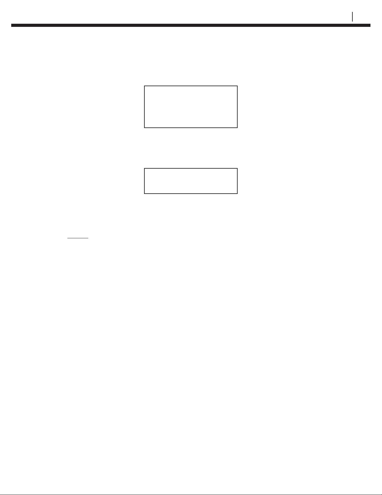
Data is now ready for transfer from the Checkmate DL to the PC. On the
Microcor Tools Software program, select the Site and navigate to the Confi g/
DL Transfer screen, select Data Logger as the Connection type and Microcor
as the Instrument (see image below). Click the Read Data command button
to begin the transmission. It is also possible to click the Read Setup command
button to transfer the confi guration data of the Data Logger to the Data Logger
section on the Confi g/DL Transfer screen.
Page 63
CHECKMATE™ DL 55
During the data transfer, the following screen will be displayed on the Checkmate
DL:
Data Transfer in
Progress!
xxxxx Readings Left
Exit
The number of readings (xxxxx) counts down as the data is transferred to
Microcor Tools. Upon successful transmission, Checkmate DL will show the
following screen:
Data Transfer Done!
Exit
Press Exit (F4) to return to the Data Transfer screen to choose another ID for
data transfer.
NOTE: Only one Data Logger information can be transferred at a time,
when transferring information of more than one Data Logger,
change the Address on the Microcor Tools Software program
for each transfer so that all data is not transferred only to one ID
address.
In case of any error messages displayed on Checkmate DL, check connections
between Checkmate DL and the PC, make sure that Microcor Tools Software
program is running and that the correct COM port is checked.
If data is still not transferred after checking the connection between the PC and
Checkmate DL, please see the Troubleshooting section for further help.
Page 64

56 TRANSFERRING DATA LOGGER DATA TO THE PC
Page 65
Troubleshooting Guide
CHECKMATE™ DL 57
CHAPTER 14
Symptom
Checkmate DL will not turn on
Checkmate DL turns off before 2
minutes auto shutdown
Checkmate DL will not transfer data
to the computer
Problem
-Batteries not installed
-Battery voltage low
-Batteries installed incorrectly
-Battery voltage low
-Corrdata Plus Corrosion
Management Software is not
running when using Corrdata
System Confi guration
-Cable is not connected properly.
-Check the COM ports
Solution
-Install batteries
-Install new batteries
-Check the polarities as indicated on
the unit
-Install new batteries
-Launch Corrdata Plus Corrosion
Management Software from the
Start Menu
-Check that the cable is fully
plugged into Checkmate DL and that
the other end is fully plugged into
the 9 pin serial port on the back of
the PC
-Check that the COM port selected
in Corrdata Plus Corrosion Management Software or Microcor Tools is
the actual COM port to which the
Checkmate DL is connected
RDC/ER-210 will not transfer data to
the Checkmate DL
Microcor Data Logger will not
transfer data to the Checkmate DL.
Inaccurate Time and Date Stamp on
Data Logger Readings
-Microcor Corrosion Management
Software is not running when using
Microcor System Confi guration
-Cable is not connected properly
-Battery voltage low on RDC/ER210
-Cable is not connected properly
-Battery voltage low on Data Logger
- Time Zone not set properly
-Launch Microcor Tools Software
from the Start Menu
-Refer to the User Manual sections
on Transferring Data from Checkmate DL to the PC for more details
-Check Connections to the RDC/
ER-210
-Install new batteries
-Check Connections to the RDC/
ER-210
-Install new battery
-Set the Standard Time Zone, refer
to the User Manual for more details
Page 66

58 TROUBLESHOOTING GUIDE
Page 67

CHECKMATE™ DL 59
Page 68

60
Page 69

CHECKMATE™ DL 61
Page 70

62
Page 71
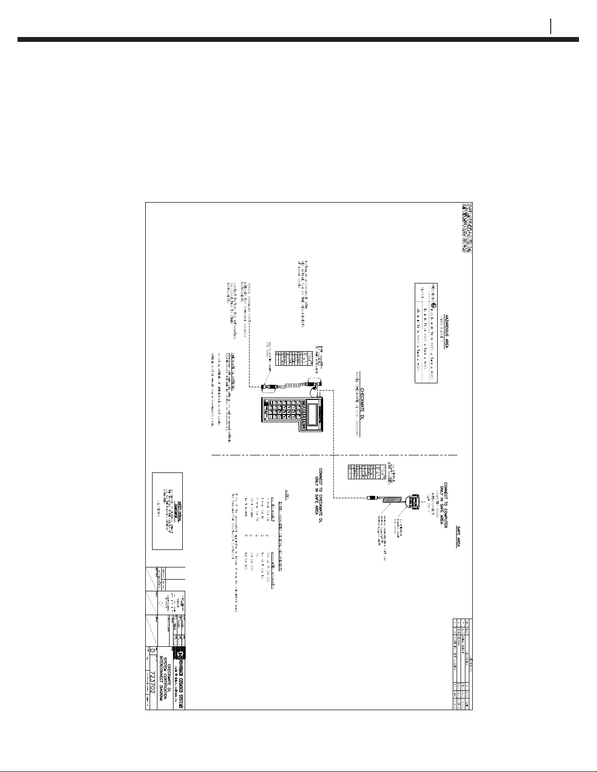
Interconnect Diagram Drawing
CHECKMATE™ DL 63
Appendix B
Figure B.1 Interconnect Diagram Drawing
 Loading...