

CORVUS H-Series, 6, 11, 20 Service Manual
THE
CORVUS
SERVICE
MANUAL
H-Series Drives
*\
CORVUSSYSTEMS
* *

DISCLAIMER OF ALL WARRANTIES & LIABILITIES
Corvus
manualorwith
chantability,orfitness for
licensed lias is:'
Systems, Inc., its distributor,orits retailer.
servicing, repair,orcorrection
Corvus
Corvus
consequential
Every
servicing of
ware
material after
errorsoromissions.
Corvus
ual at
and
This
ment
any
Corvus
Copyright© 1982
Mirror®
Logicalc,T.
Workstation,"" Tap Box,'· Passive Tap
of
Systems, Inc.
Systems, Inc.beliable for direct, indirect,
Systems, Inc.
damages,sothe
effort
has
Corvus
along
with
the
Systems, Inc.
any
time
without
maybepurchasedbywriting to:
Corvus
2029 O'Toole
San
Telephone: (408) 946-7700
TWX 910-338-0226
manual
may
electronic
Corvus
Systems, Inc.
Jose,
CA
is copyrighted
not,inwholeorin
Systems, Inc.
patent
Time
Systems, Inc.
makes
respecttothe
The
entire
has
been
madetoinsure
products.
future
date
reserves
Avenue
95131
medium
by
Corvus
pending,
Travel Editing,T. EdWord,T. Constellation,T. Corvus,T.
no
warranties,
software
any
particular
riskasto its qualityorperformanceiswith
and
any
been
advisedofthe
above
However,
products,
of publication,
notice. Revised
or
Corvus
the
righttomake
and
contains
partbecopied,
machine
Systems, Inc. All rights
The
Corvus
Box,T.
describedinthis manual, its qUality,
incidentalorconsequential
limitation
that
duetothe
nor
manuals
readable
Concept,T. Transporter,T.
FCC WARNING
This
equipment
usedinaccordance
tions. As
limits for Class A
designedtoprovide
mentina residential
expense
willberequired
generates,
temporarily
computing
uses,
with
the
permitted
reasonable
area
is likely to
to take
and
can
instruction
by
regulationithas
devices
pursuanttoSubpart
protection
whatever
cause
either
purpose.
The
this
Systems, Inc.
can
expressedorimplied,
Corvus
buyer
assumes
incidentalorconsequential
possibility of
may
not
manual
accurately
ongoing
cannot
Corvus
NOTICE
changesinthe
and
update
proprietary
photocopied,
Active
radiate
manual,
against
measures
information. All rights reserved. This docu-
form
without
reserved.
Junction
radio
frequency
may
cause
not
such
interferenceinwhich
mayberequired
Systems, Inc.
the
the
entire
damages. Innoevent
such
damages.
applytoyou.
documents
modification
guarantee
Systems, Inc.
product
sheets
willbepublishedasneeded
reproduced,
prior
consent,inwriting,
Corvus
Corvus
Box,T.
Omninet
energy
interferencetoradio
been
tested
J of
Part15of
interference.
case
to correct the interference.
with
respect
performance,
softwareissold
buyer
and
not
Corvus
cost of all
damages,
Some
the
and
updateofthe
the
accuracy of
accept
for
Operation
responsibility
describedinthis
translatedorreduced
OMNINET,T.
Systems,T.
Unif·
andifnot
compliance
FCC
Rules,
the
necessary
statesdonot
operation
printed
Corvus
Personal
are
trademarks
installed
communica-
with
which
of this
userathis
to this
mer-
will
even
and
soft-
for
man-
from
and
the
are
equip-
own
or
if
to
CORVUS DEALER SERVICE
CORVUS SYSTEMS
H-SERIES 5.25-INCH
WINCHESTER DISK DRIVE
SERVICE MANUAL
MODEL
This
document
NOTE,
simplifyaprocedure.
data
or
avoid
PART NO. 7100-04704
PUBLICATION NO. GEN/10.3-01/l.1
PUBLICATION DATE APRIL
CAUTION,
exists,
injury
these.
to
and
the
contains
care
service
three
typesofnotations.
and
WARNING.
The
CAUTION
shouldbetakentoavoid
technician
I,
1983
COVERING
6, MODEL 11, MODEL
The
NOTE
indicates
or
operator
These
indicates
that
this.
exists,
are,inincreasing
some
potential
The
WARNING
and
20
actiontobe
damagetothe
indicates
extreme
care
orderofimportance,
takentospeed
equipmentoruser
that
potential
should
be
harm
taken
or
to

CORVUS DEALER SERVICE
TABLE
OF
CONTENTS


CORVUS
DEALER
SERVICE
ListofFigures
of
List
Assembly
Specifications
CHAPTER
1.1 Scope
1.2
1.3
1.4
1.5
1.6
CHAPTER
2.1 Scope
2.2
2.3
2.4
2.5
1 -
Introduction
PurposeofEquipment.
Model
Corvus
1.5.1
1.5.2
Winchester
2 - INSTALLATION
Introduction
Receiving a
2.3.1
Environmental
Daisy-ChainingofDisk
TABLE
and
Tables v
and
Schematic
Drawings.
. . . . . . . . . . . . . . . . . . . . . . . . . . . . . . . . . . . . . . . . . . . . . . . . . . . . . . . . . ...vi
OF
CONTENTS
...'.. . . . . . . . . . . . . . . . . . . . . . . . . . . . . . . . . . . . . . . . . . . . . . . . . . . . . . . . . . . . . . . . . . . . . . . . . . . . . . .
GENERAL
of
Chapter
DESCRIPTION
' . . . . . . . . . . . . . . . . . . . . . . . . . . . . . . . . . . . . . . .
. . . . . . . . . . . . . . . . . . . . . . . . . . . . . . . . . . . . . . . . . . . . . . . . . . . . . . . . . . . . . . . . . . . .
Identification.
Disk
System
Power
Data
Disk
of
Chapter
Drive.
Diagnostic
. . . . . . . . . . . . . . . . . . . . . . . . . . . . . . . . . . . . . . . . . . . . . . . . . . . . . . . . . . . . . . . . . . . . . .
Supply.
Backup.
Drive.
. . . . . . . . . . . . . . . . . . . . . . . . . . . . . . . . . . . . . . . . . . . . . . . . . . . . . . . . . . . . . . . . . .
. . . . . . . . . . . . . . . . . . . . . . . . . . . . . . . . . . . . . . . . . . . . . . . . . . . . . . . . . . . . . . . . . . .
. . . . . . . . . . . . . . . . . . . . . . . . . . . . . . . . . . . . . . . . . . . . . . . . . . . . . . . . . . . . . . . . . . .
. . . . . . . . . . . . . . . . . . . . . . . . . . . . . . . . . . . . . . . . . . . . . . . . . . . . . . . . . . . . . . . . . . . . . . . . .
. . . . . . . . . . . . . . . . . . . . . . . . . . . . . . . . . . . . . . . . . . . . . . . . . . . . . . . .... . . . . . . . . . . . . .
Test.
. . . . . . . . . . . . . . . . . . . . . . . . . . . . . . . . . . . . . . . . . . . . . . . . . . . . . . . . . . . . . . . . .
Considerations
Drives
..
vii
..
1
1
..
1
..
1
2
..
2
..
2
..
2
..
3
3
..
3
..
3
5
5
CHAPTER
3.1 Scope
3.2
3.3
3.4
3.5
3.6
CHAPTER
4.1 Scope
4.2
4.3
4.4
4.5
4.6
4.7
3 - OPERATION
Introduction
Controls.
3.3.1
3.3.2
Power-On
Environn1ental
3.5.1
3.5.2
3.5.3
Periodic
3.6.1
4 -
Introduction
Drive
4.3.1
4.3.2
General
Disk Sealed
Controller
Data
of
Chapter.
. . . . . . . . . . . . . . . . . . . . . . . . . . . . . . . . . . . . . . . . . . . . . . . . . . . . . . . . . . . . . . . . . . . . . . . .
. . . . . . . . . . . . . . . . . . . . . . . . . . . . . . . . . . . . . . . . . . . . . . . . . . . . . . . . . . . . . . . . . . . . . . . . . . . . . . . .
Front
Bezel
LEOs.
. . . . . . . . . . . . . . . . . . . . . . . . . . . . . . . . . . . . . . . . . . . . . . . . . . . . . . . . . . . . . . .
Front
Bezel
Switches.
. . . . . . . . . . . . . . . . . . . . . . . . . . . . . . . . . . . . . . . . . . . . . . . . . . . . . . . . . . . .
Sequence
Requirements
Static Electricity 8
Line Noise 9
Temperature
Maintenance
DRIVE
of
Chapter
Regular
Checks
DESCRIPTION
. . . . . . . . . . . . . . . . . . . . . . . . . . . . . . . . . . . .... . . . . . . . . . . . . . . . . . . . . . . . . . . .
Layout
Power
dc
Supply
Power
Cables
Description
Mechanism
Firmware
Storage
..
7
7
..
7
..
7
..
7
8
8
9
9
9
..
10
10
10
,
10
11
11
12
12
12
CORVUS
DEALER
SERVICE
4.8
4.9
CHAPTER
5.1
5.2
5.3 Plastic Package "
Transportation
TheoryofOperation
4.9.1
4.9.2
4.9.3 Backplane
4.9.4 Paddleboard
4.9.5
4.9.6 Read/Write
4.9.7
5 -
DISASSEMBLY
ScopeofChapter
Introduction
5.2.1 Tools Required
5.3.1 Top
5.3.2
5.3.3 Backplane
5.3.4
5.3.5 Read/Write
5.3.6
5.3.7
5.3.8
Considerations
. . . . . . . . . . . . . . . . . . . . . . . . . . . . . . . . . . . . . . . . . . . . . . . . . . . . . . . . . . . . . . . . . . . . . ...14
Power-
Controller
4.9.2.1
4.9.2.2
Interface
Motor
Controller
Drive
Motor
Power
Front
Up 14
PCA
Controller
Controller
PCA
PCA
PCA
Control
......................................................•....................
Cover
. . . . . . . . . . . . . . . . . . . . . . . . . . . . . . . . . . . . . . . . . . . . . . . . . . . . . . . . . . . . . . . . . . . . . ...20
PCA
Cover
Mechanism
PCA
Control
Supply . . . . . . . . . . . . . . . . . . . . . . . . . . . . . . . . . . . . . . . . . . . . . . . . . . . . . . . . .... . . . . . . ...24
Bezel . . . . . . . . . . . . . . . . . . . . . . . . . . . . . . . . . . . . . . . . . . . . . . . . . . . . . . . . . . . . . . . . . . . . ...24
PCA
PCA
PCA
During
During
".. . . ...16
Seek 16
Read
and
Write 16
14
18
18
18
19
19
20
20
"20
20
20
21
21
21
21
CHAPTER
6.1 ScopeofChapter
6.2
6.3
6.4
6.5 Index
CHAPTER
7.1
7.2
7.3
6 - ADJUSTMENTS AND MAINTENANCE
Introduction
Power
6.3.1 Voltage
6.3.2 Voltage
Motor
ScopeofChapter
Introduction
Drive
7.3.1
7.3.2 EXR 31
7.3.3
7.3.4
7.3.5
7.3.6
7.3.7
7.3.8 PARK
7.3.9
Supply Voltage
Brake
Adjustment
Sensor
7 -
Diagnostics RevB
Adjustment
DEALER
CRC
UPD
VSN
FMT
PRM
7.3.6.1 MUX 32
7.3.6.2 DRIVE
SET
QUIT
Check
Check
Adjustment
(CP510)
SERVICE
25
".
. . . . .... . . . . . . . . . . . . . . . . . . . . . ...25
and
Adjustment
. . . . . . . . . . . . . . . . . . . . . . . . . . . . . . . . . . . . . . . . . . . . . . . . . . . . . . . . . . . . . . . . . ...26
25
25
25
28
DIAGNOSTICS
30
30
30
30
31
" 31
32
32
33
33
33
33
ii
CORVUS
DEALER SERVICE
7.4
7.5
7.6
7.7
Controller
7.4.1
7.4.2
7.4.3
Burn-In
7.5.1
7.5.2 L)IST
7.5.3 R)ESTART
7.5.4
Read
Track
7.7.1
7.7.2 L)IST
7.7.3 R)ESTART
7.7.4
Diagnostic
General
Description
Controller
7.4.2.1 A)
7.4.2.2
7.4.2.3 C)
7.4.2.4 D)
7.4.2.5 I) Analyze
7.
4.2.6
7.4.2.7
7.4.2.8
7.4.2.9
7.4.2.10
7.4.2.11 T) Single
7.4.2.12
7.4.2.13
Error
Codes
Program
C)ONT
Q)UIT
Burn-In
Results
Diagnostic
C)ONT
Q)UIT
Diagnostic
Abort
B)
Macro
Change
Download
J)
SingleDoSeek
L)
Full
P)
Print
Q)
Sector
S)
Read Scan
X)
Write Scan
Y)
Rezero
Commands
Diagnostic
Menu
Slot
Servo
Cylinder
Quiet
Quiet
Disk
Cylinder
Heads
Number
Diagnostic
Loopseek
Summary
Program
Seek
Disk
Report
Scan
34
34
34
34
35
35
"
35
36
"
36
36
"
36
"
36
"
37
37
37
37
38
"
38
38
38
38
39
39
39
39
39
40
40
CHAPTER 8 -
8.1 Scope
8.2
8.3
8.4
8.5
Introduction
Tools 41
Error
8.4.1
Troubleshooting
8.5.1
8.5.2
8.5.3
8.5.4
FAULT
of
Chapter
Codes
Interpreting
On-Site
Isolate
Drive
8.5.3.1
8.5.3.2
8.5.3.3
8.5.3.4
8.5.3.5
Link
8.5.4.1
8.5.4.2
8.5.4.3
8.5.4.4
8.5.4.5
8.5.4.6
ISOLATION PROCEDURES
Error
Codes
Procedures
Checks
the
Problem
Not
Ready " "
Interface
Controller
Power
Drive
Drive
Inoperative
Check
Power
CRC
Controller
Servo
Controller
Firmware
Supply
Voltages "
Electronics
Sealed
Mechanism
Link Action ,
Supply
Test
Communication
Action
Firmware
, "
"
,
iii
41
41
" 41
41
45
45
"
45
46
46
46
46
46
47
47
47
47
47
48
48
48
CORVUS DEALER SERVICE
8.6
8.7
8.8
Final
8.6.1
8.b.:? Install
8.6.3
8.6.4
8.6.5
Trouble
Common
Appendix A
Appendix
Appendix
Adjustments
B
C
8.5.4.6
8.5.4.7
8.5.4.8
CRC
CRC
Power
Burn-In
Shooting
Symptoms
Glossary
H-Series
Internal
and
Test
and
Test
Test
Supply
Test
Flowchart
and
Parts
Cabling
Boot
ROM
Interface
Drive
Components
Initialization
Tests
Mirror
Recommended
List
Chart
Solutions
48
48
48
49
~
~
49
49
49
49
49
50
51
56
58
59
iv

CORVUS DEALER SERVICE
LIST
OF
FIGURES
AND
TABLES

CORVUS DEALER SERVICE
Figure 1
Figure 2
Figure
Figure
Figure
Figure
Figure
Figure 8
Figure 9
Figure
Figure
Figure
Figure
Figure
Figure
Table 1
Table 2
Table 3
H-series
Mirror
3
4
5
6
7
10
11
12
13
14
15
Rear
Controller
Front
Data
Drive
Sector
Drive
Stepper
Read/Write
Motor
CPSI0
Bra.ke
Index
Decimal disk
Hexidecimal disk
Signed
LIST
OF
FIGURES
AND
TABLES
Illustrations
drive 1
switches.
bezel.
bezel.
configuration
mechanism
interleaving
mechanism
motor
Control
power
mechanism
sensor
. . . . . . . . . . . . . . . . . . . . . . . . . . . . . . . . . . . . . . . . . . . . . . . . . . . . . . . . . . . . . . . . . . . .
. . . . . . . . . . . . . . . . . . . . . . . . . . . . . . . . . . . . . . . . . . . . . . . . . . . . . . . . . . . . . . . . . . . . . . . . .
address
PCA
switches
. . . . . . . . . . . . . . . . . . . . . . . . . . . . . . . . . . . . . . . . . . . . . . . . . . . . . . . . . . . . . . . . . . . . . . . .
components
. . . . . . . . . . . . . . . . . . . . . . . . . . . . . . . . . . . . . . . . . . . . . . ...14
block
diagram
assembly
removal
PCA
removal
supply
adjustment
adjustment
. . . . . . . . . . . . . . . . . . . . . . . . . . . . . . . . . . . . . . . . . . . . . . . . . . . . . . . . . . . . ...29
Tables
error
codes
error
codes.
. . . . . . . . . . . . . . . . . . . . . . . . . . . . . . . . . . . . . . . . . . . . . . . . . . . . . . . . . . ...43
decimal disk
error
codes
..
4
..
5
6
..
8
11
13
15
17
22
23
26
27
42
44
v

CORVUS
DEALER SERVICE
LIST OF ASSEMBLY
AND
SCHEMATIC DRAWINGS

CORVUS DEALER SERVICE
LIST
Final Assembly,
Base Assembly,
Cover
Assembly,
Backplane Assembly,
CP5IO
CP
CP5IO
CP5IO
Controller
Controller
Controller
Controller
Controller
Controller
Controller
Motor
Motor
Motor
Motor
Motor
Motor
Read/Write PCA,
Read/Write PCA, PIN 263-0238I-xxx Schematic . . . . . . . . . . . . . . . . . . . . . . . . . . . . . . . . . . . . . . . . . . . . . ...(2of3)
Read/Write PCA, PIN 263-0238I-xxx Schematic . . . . . . . . . . . . . . . . . . . . . . . . . . . . . . . . . . . . . . . . . . . . . .
'Read/Write PCA, PIN 263-0238I-xxx
Read/Write PCA, PIN 263-02I57-xxx
Read/Write PCA,
Read/Write PCA, PIN 263-02I57-xxx Schematic
Read/Write PCA,
510
Power
Power
Power
Power
Control
Control
Control
Control
Control
Control
H-Drive
H-IJrive.
H-Drive
Supply
Supply Schematic . . . . . . . . . . . . . . . . . . . . . . . . . . . . . . . . . . . . . . . . . . . . . . . . . . . . . . . . . . . . . . . . . . .
Supply
Supply
PCA, PIN 263-02323-xxx Schematic
PCA, PIN 263-02323-xxx Schematic
PCA, PIN 263-02323-xxx Schematic (3of6)
PCA, PIN 263-02323-xxx Schematic
PCA, PIN 263-02323-xxx Schematic
PCA, PIN 263-02323-xxx Schematic
PCA,
PIN
PCA, PIN 263-024IO-xxx
PCA, PIN 263-024IO-xxx
PCA, PIN 263-024IO-xxx Assembly 77
PCA, PIN 263-0I908-xxx
PCA,
PCA, PIN 263-0I908-xxx
PIN
PIN
PIN
OF
ASSEMBLY
. . . . . . . . . . . . . . . . . . . . . . . . . . . . . . . . . . . . . . . . . . . . . . . . . . . . . . . . . . . . . . . . . . . . . . . . .
H-Drive
Assembly.
Parts
Parts
263-02323-xxx
PIN
263-0238I-xxx Schematic . . . . . . . . . . . . . . . . . . . . . . . . . . . . . . . . . . . . . . . . . . . . . ...(1of3)
263-02I57-xxx Schematic
263-02I57-xxx
. 63
List
List (2of2)
Assembly.
Schematic.
Schematic.
Schematic.
263-0I908-xxx
Schematic.
Assembly.
Assembly.
Schematic.
Assembly.
AND
. . . . . . . . . . . . . . . . . . . . . . . . . . . . . . . . . . . . . . . . . . . . . . . . . . . . . ...74
. .
. .... . .... . . ....
. . . . . . . . . . . . . . . . . . . . . . . . . . . . . . . . . . . . . . . . . . . . . . . . . . . . ...88
SCHEMATIC
. . . . . . . . . . . . . . . . . . . . . . . . . . . . . . . . . . . . . . . . . ...(1of2)
. . . . . . . . . . . . . . . . . . . . . . . . . . . . . . . . . . . .... . . ...(2of2)
. .... . . . . . . . . . . . . . . . . . . . . . . . . . . . . . . .... . . ...(1of2)
. . . .... . . . . .... .... . .... . . . . . . . . . . . . . . . . . ...(2of2)
. . . .... . . . . . . . . . .... . . . . . . . . . . . . . . . . .... . . . . . . . . .
.......
. . . .
....
. . . . . . . . . .... . . . . . . . . . . . . .... . . . . . ...84
DRAWINGS
......
. . .... . . . .....
. . .
....
..
(1of2)
(1of6)
(2of6)
(4of6)
(5of6)
(6of6)
(3of3)
(1of3)
(2of3)
(3of3)
60
..
61
62
64
..
65
66
67
68
69
70
71
72
73
75
76
78
79
..
80
81
82
83
85
86
87
vi

CORVUS DEALER SERVICE
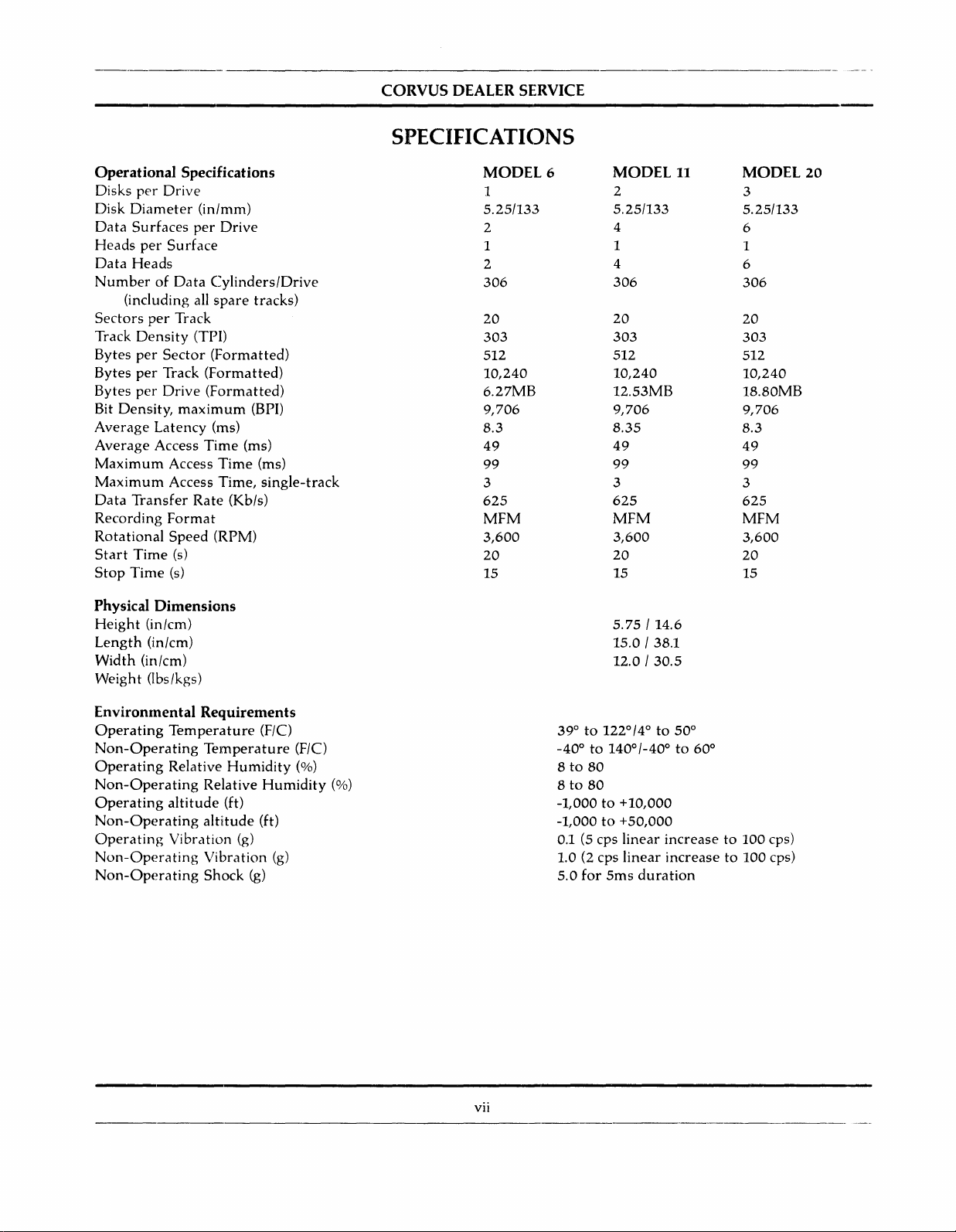
SPECIFICATIONS
CORVUS DEALER SERVICE
SPECIFICATIONS
Operational Specifications
Disks
per
Drive
Disk
Diameter
Data
Surfaces
Heads
per
Data
Heads
NumberofData
(including all
Sectors
Track
Bytes
Bytes
Bytes
Bit
per
Density
per
per
per
Density,
Average
Average
Maximum
Maximum
Data
Transfer
Recording
Rota
tional
Start
Time
Stop
Time
Physical
Height
Length
Width
Weight
(in/cm)
(in/cm)
(in/cm)
Obs/kgs)
(in/mm)
per
Drive
Surface
Cylinders/Drive
spare
Track
(TPI)
Sector
Track
Drive
(Formatted)
(Formatted)
(Formatted)
maximum
Latency
Access
Access
Access
(ms)
Time
Time
Time,
Rate
Format
Speed
(RPM)
(s)
(s)
Dimensions
tracks)
(BPI)
(ms)
(ms)
(Kb/s)
single-track
MODEL
1
5.25/133
2
1
2
306
20
303
512
10,240
6.27MB
9,706
8.3
49
99
3
625
MFM
3,600
20
15
6
MODEL
2
5.25/133
4
1
4
306
20
303
512
10,240
12.53MB
9,706
8.35
49
99
3
625
MFM
3,600
20
15
5.75
15.0/38.1
12.0/30.5
/14.6
11
MODEL
3
5.25/133
6
1
6
306
20
303
512
10,240
18.80MB
9,706
8.3
49
99
3
625
MFM
3,600
20
15
20
Environmental Requirements
Operating
Non-Operating
Operating
Non-Operating
Operating
Non-Operating
Operating
Non-Operating
Non-Operating
Temperature
Temperature
Relative
Humidity
Relative
altitude
(ft)
altitude
Vibration
Vibration
Shock
(F/C)
Humidity
(ft)
(g)
(g)
(g)
(F/C)
(%)
(%)
vii
1220/4
14001-40
0
to
390to
-400to
8to80
8to80
-1,000to+10,000
to
for
+50,000
linear
linear
5ms
duration
-1,000
0.1 (5 cps
1.0 (2 cps
5.0
0
50
0
0
to
60
increaseto100
increaseto100
cps)
cps)
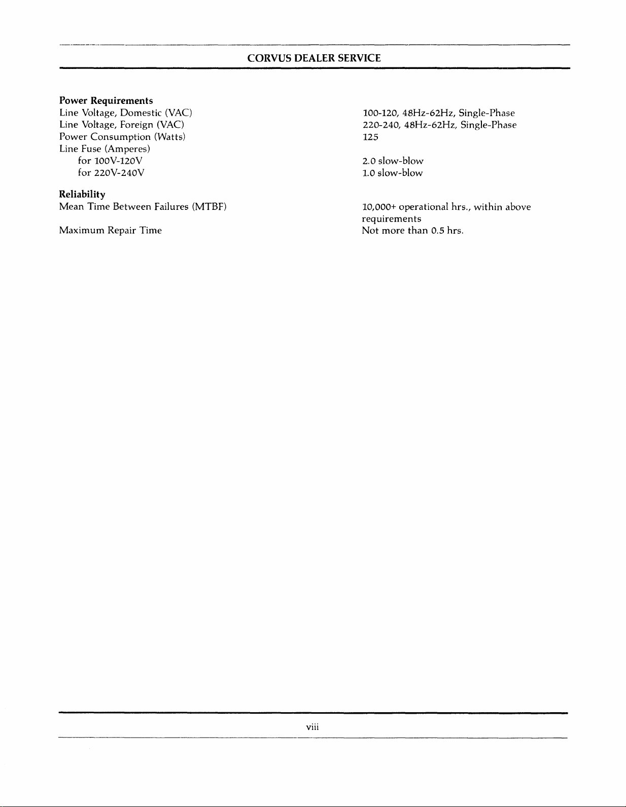
Power Requirements
Line Voltage,
Line Voltage, Foreign (VAC)
Power
Fuse
Line
for
for
Domestic
Consumption
(Amperes)
100V-120V
220V-240V
(VAC)
(Watts)
Reliability
Mean
Time
Maximum
Between
Repair
Failures (MTBF)
Time
CORVUS
DEALER
SERVICE
100-120,
220-240,
125
2.0
1.0
10,000+
requirements
Not
48Hz-62Hz,
48Hz-62Hz,
slow-blow
slow-blow
operational
more
than
0.5
hrs.,
hrs.
Single-Phase
Single-Phase
within
above
viii
CORVUS
DEALER SERVICE
CHAPTER
GENERAL
1
DESCRIPTION
CORVUS
DEALER SERVICE
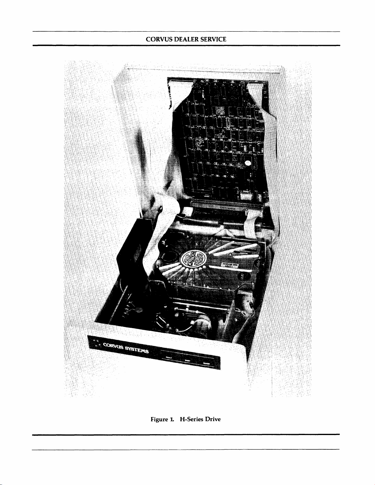
FigureLH-Series
Drive
CORVUS DEALER SERVICE
General
Description
1.1
This
ScopeofChapter
chapter
outlines
Brief description
1..2
This
Repair
and
Dealer
The
Introduction
document
procedures
all
non-H-Series,
Serviceisonamodular
H-Series
drives
18-megabytes
same
drive
enclosure
identify
in this
the
typeofdrivetobe serviced.
document.
Also included in
Servicing dealer.
disk drives.
software
Installation
operation,
The
specifictothese
and
see
the
the
purposeofthe
and
layout
contains
for
A-series
instructions
5.25-inch,
are
manufacturedinthree
(Model 20).
These
usedbyseveralofthe
this
manualisdocumentation
These
utilities
initialization
drive
operationofthe
Corvus
"Disk
CHAPTER
GENERAL
Corvus
Systems™H-Series™Model6,Modellland
DESCRIPTION
1
is include, as is a definitionofWinchester
for
(8-indl,
6-megabyte)
replacement
drives all
provide
and
diagnostic
models. Use
disk
drive
Systems
maintenance
II-megabyte
drives as
basis,
use
B-series, 5.25-inch,
Instructions
for
burn-in/reliability
utilities
the
are
not
Installation
and
Rev A)
are
and
this
capacities:
the
same
for
troubleshooting
on
the
Dealer
for
appropriate
covered
Guide"
repairofthe
drives
and
networks
and
manualiswrittentoaddress
6-megabytes
grey
high-impact
6-megabyte
Service
testing,
the
H-Series
A-, B-
and
in detailin
and
Corvus
technology.
Corvus
Systems
H-Series,5.25-inchdisk drive.
B-series (8-inch, 11-
other
Corvus
equipment.
this
(Model 6),
12-megabytes
foam-injection plastic cabinet.
drives.
and
repair
Diagnostic
adjustment,
drives
are
H-Series
this
manual.
"Disk
Checking
for
all
H-Series
Utilities suppliedtoeach
and
troubleshootingofall
uniquetothe
software
For
Systems
only
instructionsininstallation
User Guide."
Model20disk
and
20-megabyte
Corvus
policy.
(Model
the
serial
drives
H-Series,
for
the
drives. A
(tm) Level I
Thisisthe
number
are
and
proper
Rev
B,
II),
and
will
detailed
Corvus
Corvus
contain
drives.
and
1..3
The
microcomputer
disk
ordered
1.4 Model Identification
The
The
manufacture
The
PurposeofEquipment
Corvus
system
three
Model 6
following is a
disk
drive
with
consistsofthe
withahost
Corvus
uses
date
storage
interface, 34-pin
H-Series
one
maybedetermined
sample
is a
platter,
serial
andisdecoded below:
350
Whenever
represents
02
represents
3
represents
B
H
representsanH-Series
represents
/M
represents
communicating
the
the
a Model 11 drive (A=Model6,C=Model
the
that
with
involved.
"'Corvus
"'Mirrorisa
™H-Series
TI'Z-80
Systemsisa
registered
isaregistered
isaregistered
registered
trademarkofCorvus
trademarkofZilog, Inc.
trademarkofCorvus
trademarkofCorvus
high-speed,
and
ret
5.25-inch disk
disk drives
the
numbertobe
intelligent
rivalofdigital
mechansim,aZ_80™
interface
are
Model 11
from
flatcable
identical, differing
uses
the
serial
foundona
mass-storage
information
two,
023-BH350/M
weekofmanufacture
(week 02)
yearofmanufacture(3for
drive
serial
numberofthat
this
drive
was
years'
shipped
CorvusinreferencetoCorvus
Systems,
Systems,
Inc.
Inc.
Systems,
instantlyatthe
intelligent
and
Corvus
onlyinthe
and
the
Model20uses
number
tag
Corvus
1983)
manufacture
withaMirror™
products,
Inc.
peripheral
disk device
requestofthe
controller
designedtoprovide
host
and
power
Utility diskettes.
internal
locatedatthe
layoutofthe
three.
The
rearofthe
drive type, capacity,
H-Series, Model 11 disk drive:
20)
installed
internally
include
the
serial
numberofthe
system.
supply,
drivesealed
drive cabinet.
the
host
The
Corvus
and
may
be
mechansim.
and
equipment
1
General
Description
CORVUS DEALER SERVICE
1.5 The Corvus
The
Corvus
International
minimal
procedures
appropriate
All
H-Series
single
The
Mirror
software
power
Mass-Storage
Memories,
are
computer
drives
supply,
PCA
backplane, located inside
1.5.1 Power Supply
All
H-Series
single
1.5.2 Data Backup
Data
backupisaccomplished via
format
comes
drives
power
supply.
whichisthen
internaltothe
software-controlled,
repairiscoveredinthe
1.
6 Winchester disk drive
The
Corvus
disk
environment,
surface
and
closely
storage
regular
after
power-down.
recording
media.
relatedtohead-media
capacitiesata
maintenance.
Disk
Inc (lMI).
setup.
coveredinthe
system.
consistofa 5.25-inch
Z-80
(when
installed)
the
operate
These
storedonvideo
drive
remote-control
Corvus
drive
uses
and
low-load,
This
premiumofspace.Anadded
System
Disk
System
utilizes a sealed 5.25-inch
The
drive,
Interfacingtohost
corresponding
drive
Controller
top
from
power
and
cover.
either
supplies
the
PCA,
Z-80
110-120YACor220-240YAC,
Corvus
cassette
when
it is
ordered,oraddedasan
interfacetoa Panasonic™
Mirror
the
IMI
low-mass,
It is
the
resultsinthe
clearance
Service
Winchester
aerodynamically-suspended
contaminant-free
heads
and
with
its
computers
"Disk
System
mechansim
and
cooling
intelligent
are
interchangable
Mirror™.
tape,
using
Manual.
disk
environment
ridingonan
head
mass,
advantageofthe
Winchester
intelligent
controller,isdesigned
is via 34-pin flat-cable
Installation
(with
integral
fan
mounted
Controller
PCA
between
The
Mirror
converts
oneofmany
external
YCR
mechansim.
This
read-write
that
18-micro-inch
disk
drives
utilizing
Winchester
Guide"
and
Read/Write
in a
grey
plastic cabinet.
are
plugged
50Hzor60Hz
all
H-Series
the
commercial
device later. All
model
NY-8200.
new
generationofdisk
heads
allows
for
reduction
air
bearing,orair
Winchester
sealed
disk
mechansim
as a
interface.
"Disk
System
PCA)
into
single-phase
plug-in
and
the
manufactured
device,
Installation
User
Guide"
Motor
two
Control
card
power,
drives.
data
from
digital
formattovideo
YCRs.
The
Mirrors
Mirror
which
rest
in clearance
cushion.
technology
Corvus
are
Mirror
available
troubleshooting
drive
utilizes a sealed
directlyonthe
between
Sincebit
can
achieve
mechansimisthatitrequires
by
requiring
and
setup
for
the
PCA,
slotsofthe
and
use
option
with
and
disk
head
density
large
no
a
a
is
™Panasonic is a
registered
trademarkofPanasonic,
Inc.
2

CORVUS
DEALER SERVICE
CHAPTER 2
INSTALLATION
CORVUS DEALER SERVICE
CHAPTER 2
INSTALLATION
Installation
2.1 Scope of
This
chapter
proper
Systems
2.2
operation.
Installation
Introduction
Each drive,
contains
2.3 Receiving a Drive
Any
Corvus
these
timeadrive
disk
Chapter
discusses
Installation
Guide"
whenitis
check-out
drive
received,
is received,
shouldbecarefully
installationofthe
and
operation
and
"Corvus
shouldbechecked
procedures
several
as well as
checks
unpacked
maybesymptomaticofdamagetofragile
Any
damage
claims
mustbereportedtothe
Also, if
the
damaged
procedures.Ifthe
Merchandise
The
disk drive
force
This
(one
necessitates
mechanisminthe
gravity)
very
Whenadriveisreceived,
loose
during
1)
Remove
careful
2)
Locate
3) Locate
securely
4)
Replace
5)
Replace drive
shipping
the
two
nottostress
the
Mirror
the
Controller
into
their
Mirror
cover
equipmentisa
damaged
Authorization
equipmentisa
number),
Corvus
willbeamplified
careful
account
screws
handlingofthe
check
that
forapercentageofthe
securing
thedcpower
PCA
(if installed)
PCA
installed
sockets.
PCA.
and
secure
new
and
all chipsinthe
the
cable
with
disk
drive
hardware
procedures
Disk
Systems
for
shipping
those
for
shouldbeperformed
and
checked
mechanisms
within
NOTE:
local
officeofthe
product,
contact
disk
transmittedtothe
plugged
behind
screws.
Corvus
recently
Corvus
systemisan
drive
cabinet
and
flatcables
into
the
Order
serviced
Customer
mechanism
2-80
Controller
failures
covertothe
the
Mirror
as it appliestoenvironmental
for
the
User
Corvus
Guide."
damage,
disk
and
system
tested
installing single drives
before
the
driveisinstalledatthe
for
shipping
the
shippersoan
Processing
product
Service
extremely
heads,
damage.
drive.
inspection
Department
being
returned
Department
sensitive
impacting
maybemade,
them
bothinshipping
PCA
are
seated
upon
reciept.
drive
basepanatthe
connectingtothe
lowerofthe
PCA,
and
two
press
Controller
card
firmlyonall
are
outlinedinthe
for
proper
and
multiple-drive
External
andadamage
mustbecontacted
underanRMA
for
proper
return
device.
onto
and
Subjecting
the
operation.
well in
rear,
PCA
slotsofthe
socketed
requirements,toinsure
"Corvus
function.
This
systems.
customer
site. Each
evidenceofrough
report
filed.
for
proper
return
number
(Return
procedures.
the
drivetoa
platter
their
and
backplane,
with
a 100-g force.
sockets.
remove
and
Chips
the
Backplane PCA.
and
chips,
seating
cover. Be
remove
Disk
chapter
handling
one-g
coming
it.
them
2.3.1 Diagnostic Test
Upon
recieptofa disk drive,
1) Verify
2) Verify
3)
4)
5) Execute
6)
7) Execute EXERCISE Utility
Check
Check
Check
front
bezel
Mirror
Switch
Controller
power
supply
CRe
Test
Parameters
several
switch
positions (on
Firmware
Voltages
(drive
procedures
positions
VERSION
and
MUX)
mustbeexercisedtoverify
rear
bezel)
and
recordonpaper
the
proper
3
functioningofthe
equipment:
Installation
8)
Run
BURN-IN Diagnostic (destructivetodata)
9)
Update
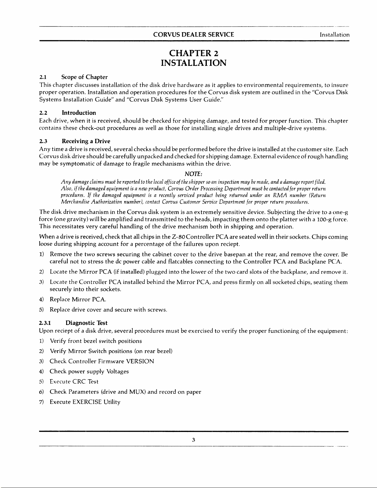
Any
Corvus
plugs
locatedonthe
installedornot).Ifthese
proper
combination.
into
switch
Controller
disk
drive
the
Backplane
rearofthe
configuration).
Firmware
maybeordered
PCA
cabinet,
switches
(drive Diagnostic
alongside
which
are
Drives
CORVUS
withaCorvus
the
Controller
MUSTbesettocorrectly
not
set
properly,
usingaMirror
DEALER SERVICE
option
Mirror
PCA,
the
UPD)
changing
PCA
inside
drive
may
externally
tables
when
prompted
installed. In all S.2S-inch drives,
the
cabinet
reflect
not
should
the
internal
function
use
cover.
properly
the
The
drive
Mirror
(refertothe
"No
has
configuration
Mirror
(answer
the
Mirror
four
DIP
chart
Installed"
"yes")
PCA
switches,
(whether
below
for
switch
MIRROR
Check
the
drive
power
details).
Next,
thoroughly
manual). Execute a
the
Virtual drive
utility
to
reset
themtotheir
A
new
drive
may
be shipped
onanew
Parameters
reference.
the
In
utility
parameters
and
Default
Be
suretocheck
Spare
priortoformatting
drive,
are
first
event
that
shouldbeused
before
therefore
Track
necessitate
parameters
Spare
Track table:
VDO
table:
Interleaving Spec: all H-Series drives
the
table
1 2 3 4
Pushed
in
~~~
OPEN
DRIVES WITH NO
OR
EXTERNAL MIRROR:
The shaded area indicates that the switch should be pushed in on that side.
supplyvoltages
test
the
drive,
CRC-Format
Offset
which
the
table). If
appropriate
withupto
leaves a
checked,
drive
only
attempting
are:
Model6
Model 11 drive 1 =0
Model20drive 1 = 0
drive
and
VDO
the
the
formatisdisturbedinshipment,itmaybenecessarytoreformat
as a last
the
re-initializationofthese
no
parameters
table
drive will simplify this
Figure 2.
and
using
the
Check,
eitherofthese
twenty-four
minimumofseven
values
resort.
FORMAT
tracks
spared
drive 1 = 0
(drive 2 = 911
before
may
need
Mirror
adjustifnecessary
Dealer
as well as verify
tables display values
values.
shouldbenoted,
Using
utility.
must
= 9
and
after
reconstructing
procedure.
234
~~
OPEN
DRIVES WITH
PAUSECAM MIRROR:
Configuration Switches
(refertoChapter6,"Adjustments
Service Diagnostics (as
the
drive
tracks
spared.
(and
the
PARAMETERS diagnostic utility,
The
format
parameters
be added
formatting
before
Noteonthe
There
most
likely
recordedona label,
program
with
after
the
the
outlinedinChapter7"Diagnostics"ofthis
Parameters
outofrange,
areatotalofthirty-one
more)
will
restore
the
original values (i.e. previously
FORMAT)
drive.Ifthe
dataisrestored.
label,
any
2 3 4
~~~
OPEN
DRIVES WITH
NTSC MIRROR:
(specifically
use
for
useinthe
and
attachedtothe
drive
future
the
the
PARAMETERS diagnostic
the
first
default
Knowing
parameterstothe
has
ever
tracks spared.
and
Maintenance"
Spare
Track table
spare
tracks available
field.
When
drive
drive.
The
trytorestore
spared
hadatrack
what
tracks
and
the
drive
for
future
FORMAT
the
drive
drive,
tracks).
spared,
are
the
spared
for
4
CORVUS DEALER SERVICE
Installation
2.4
All
the
Environmental Considerations
electronic
drive.
equipment
There
cushionorcarpet;
monitor
on
top
malfunction.
Be
sure
the
proper
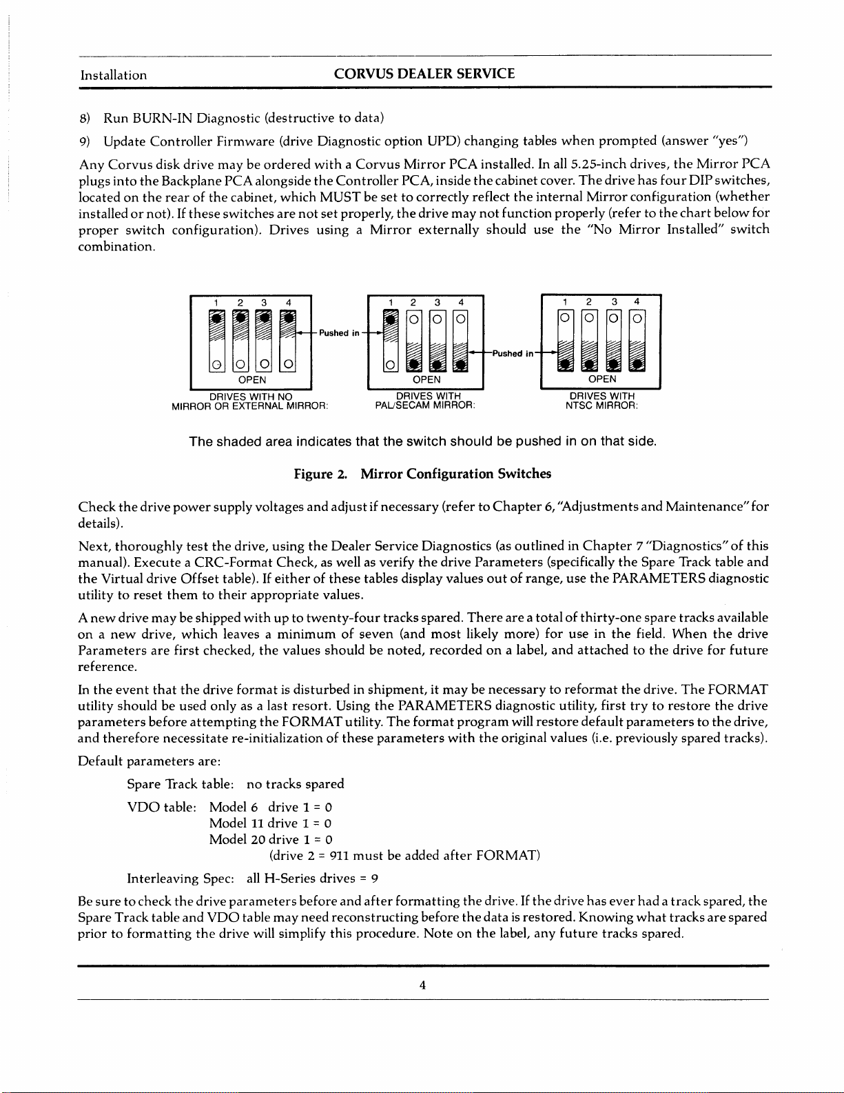
Insure
the
stripe)isto
the
interface
PROCESSOR
the
needs
cooling
shouldbesufficient
the
air
intake
slots
of,ornear
line
voltage
the
has
cableisproperly
connectoronthe
right,
when
facing
Connects
to
Video
Recorder
and
open
areonthe
Corvus
been
connected
rear
the
rearofthe
Video
0
the
Corvus
area
both
bottomofthe
drive.
Electromagnetic
selected
between
bezelofthe
Connects
Remote
Control
VIDEO
IN VCR REMOTE
to
OUT~
and
Corvus
drive
disk
driveisno
front
and
cabinet,
proper
fuse
the
connectoronthe
disk
unit.
Connects
to
Interface
Card
•
exception.
rear. Place
and
fields
generated
sizeisinstalled.
drive
cabinet.Besure
Connects
to
Add-on
Drive (If any)
PROCESSOR
,:
Bi
DRIVE
:I
:1
When
installing,donot
the
driveona level,
must
notberestricted.Donot
by
this
interface
Air
the
Flow
cardinthe
"one"
Slots
III
0
hard
device
edge
"pigeon-hole"
surface
may
host
computer,
(edge
without
place a
cause
with
video
drive
and
dark
Check
switches.
ortoa
Locate
bezel
the
after
drive
2.S
A
accomplished
Corvus
additional disk
exceptionofthe
must
™DEC is a
™LSI_ll is a
that
all
four
All
switches
DEC™
the
Light
LSI-11™
power
Emitting
switchonthe
FAULT LED willgoout,
which
the
drive
is
now
ready
Daisy-Chaining of Disk Drives
maximumof80
by
usingacommon
add-on
use
registered
drive
driveinthe
Rev A,
Controller
trademarkofDigital
registered
Mirror
front
panel
switches
shouldbeto
computer.Ifso,
rearofthe
Diodes) will
will
for
communication
set
and
the
come
the
megabytesofon-line
areinthe
the
left,
the
on,
heads
READY
with
unless
appropriate
drive,
and
will
signal,
the
storage
input/output
flat cableisavailable specifically
system.
8-inch
Firmware
trademarkofDigital
All series
11MB disk
version
CF18.3orlater.
Equipment
Equipment
drive
Corporation
Corporation
Dip
Switches
Power
Switch
Figure 3. Rear Bezel
correct
the
and
the
BUSY LEDwill flash regularly.
rezero.
and
host
maybeachievedbydaisy-chaining
interface
and
(Rev A
position.
disk
driveisconnectedtoa
switches
turniton.
Run
your
shouldbeset.
The
drive
LED activitywill briefly
all LED
activity
will cease,
system.
bus,
commonly
for
this
purpose.
One
Versionsofdisk drives
drives
maybedaisy-chained
finger
motor
referredtoas daisy-chaining. A special
maybedaisy-chained
Connects
toAC
Cable
along
Corvus
will
After
alternate
with
add-on
from
righttoleft,
Multiplexer
begintospin,
approximately
between
the
READY
four
Model 20 drives.
drive
cableisrequired
onlytoother
under
Network
and
all LEOs
thirty
READY
LED on.
system,
seconds,
and
BUS~
The
(front
This
for
together
with
Rev A drives). All
the
disk
is
each
the
5
Installation
CORVUS
DEALER SERVICE
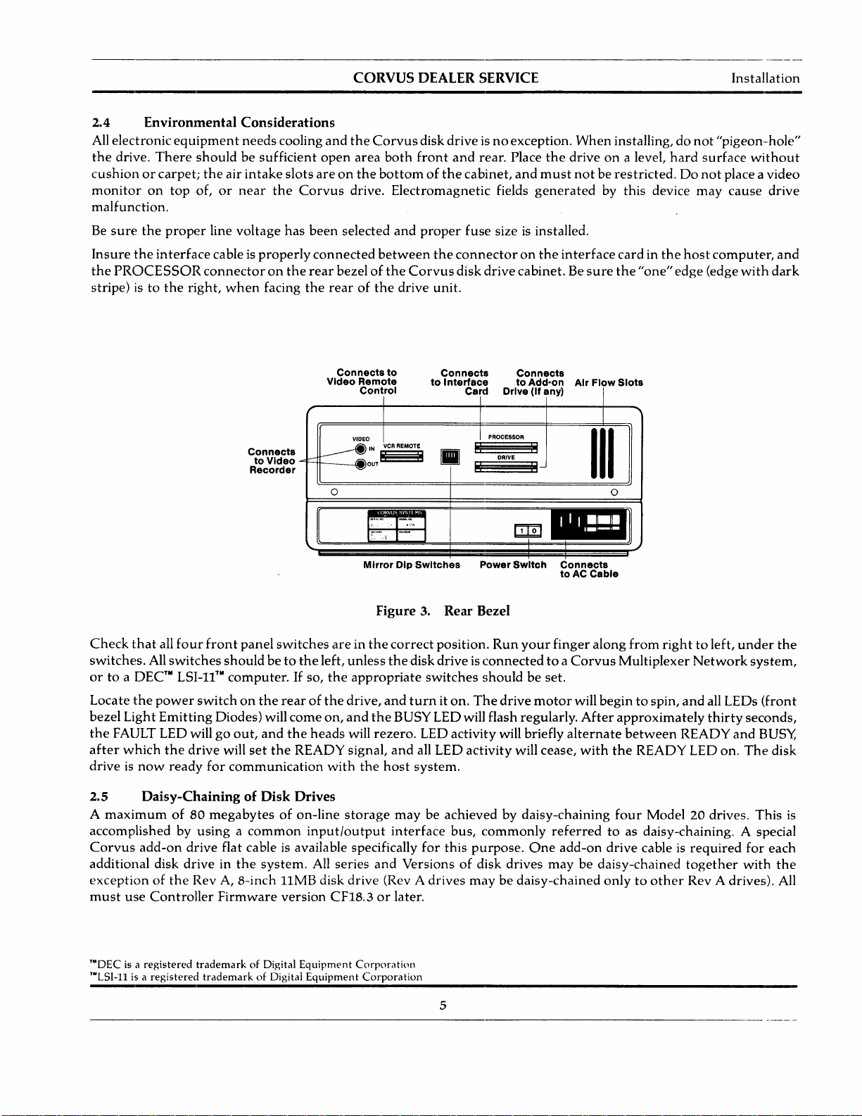
Changing
required
shouldbeset
Guide"
For
Guide"
the
when
for
complete
and
unit-select
daisychaining
accordingtotheir
the
appropriate
installation
"Disk
System
switches
computer
and
User
(positions 1
drives.
New
positioninthe
system.
initialization
Guide."
t'/
12345678
and4)on
drives
are
daisy-chain (2, 3
procedures,
shipped
~HHHH
~
,,/---------t'/
1
234
o~
iffnlTln
5 6 7 8
the
with
refertothe
~7
--¥V
V
drive
2-80
Controller
the
switches
or
4).
Refertothe
appropriate
DRIVE ADDRESS 1
DRIVE ADDRESS 2
PCA
for
each
add-on
configuredasdrive1.Additional drives
Corvus
Corvus
"Disk
"Disk
System
System
drive
Installation
Installation
is
,,/----------1"/
1
234
5 6 7 8
DRIVE ADDRESS 3
~HHHH/
,c./---------t'/
1
234
~HHHH
~
5 6 7 8
DRIVE ADDRESS 4
___IV
Figure 4. Controller Address Switches
6
CORVUS
DEALER SERVICE
CHAPTER
3
OPERATION
--------------------------------_._-----------------------._--_.-.-
CORVUS DEALER SERVICE
CHAPTER 3
OPERATION
Operation
3.1 Scope of
This
chapter
control
are
switches
discussed,
Operation
operating
3.2
All
properly
system.
Introduction
Corvus
reflecting
bezel display
3.3
Operator
Controls
controls
controller.
selection
unit
Chapter
describes
and
and
and
initialization
S.2S-inch,
the
stateofthe
Four
function
(CORCOM),
operator
Light
Emitting
recommended
instructions
H-Series
the
system
are
locatedonthe
switches
power
processor, daisy-chained drive,
3.3.1 Front Bezel LEOs
The
LEOs
are
labled READ'Y,
the
drive
while
signal will be
During
processor.
The
FAULT LED is active
LED is
during
set,
normal
The
an
indicatorofdrive
normal
motor
BUSY LEDisactive
reaches
the
READY LED will be on,
operation,
the
when
operation.
FAULT LED
screen.
3.3.2
The
FORMAT,
be
settothe
All
configuration.
Located
ON
determine
from
The
ON
switchtodetermine
Firmware
Front Bezel Switches
function
switches
(right)
the
next
(right)
switches
RESET
left.
except
Only
furthesttothe
positionisfor
if a
DEC
Controller
switch,
the
positionisfor
area
into
are
During
for
the
normal
the
RESET
left,
use
LSI-II
computerisattached,
Firmware
MUX
switch,
use
if a
Multiplexerisattached,
controller
controls
drives
Diodes
regular
have
and
their
are
checks
are
detailed in
front
use
described,
for
the
bezel
configurationinorder
drive,
and
helpindiagnosing
front
bezelofthe
are
switch,
and
remote
BUS'Y,
and
operating
READY
when
command
located
LED is active
under
video
connectors,
control
FAULT
speed.
the
driveiscurrently
After
and
VCR
During
the
execution
has
malfunctionoroperational
functionisaccompanied
located
the
below
operation,
RESET
switch
LSI
switchisa
switch
directly
withaDEC™
the
LEOsonthe
in a
single-user
are
affects
two-position
System
polled
and
area
into
with
is also a
the
Corvus
controller
two-position
RAM.
Multiplexer
and
RAM.
as appliestotroubleshooting
and
their
drive
the
Corvus
indicator
for
the
the
enclosure.
the
LEOs.
Mirror
interface
the
the
drive
BUSY
when
the
functions
are
given.
"Disk
lights
and
drivetofunction
conditionofthe
Three
Rear
bezel
configuration
cables.
power-up
has
completed
and
FAULT LEOs willbeoff.
driveisreadytoreceiveacommand
detailed.
System
function
LEOs
components
sequence
executingacommand
been
interrupted
error,
although
duetothe
some
byanerror
front
bezel.
These
system
by
the
hardware.
switch;
LSI-II™.Atpower-on
loads
the
switch;
withoutanLSI-II
the
controller
the
DEC
RLOI™
the
OFF
ROM
OFF
(left) positionisthe
time,
and
(left)
positionisthe
Network™.Atpower-on
loads
the
the
Multiplexer
and
repairofthe
Environmental
User
Guide"
switches.
properly.
Indicator
driveatany
monitor
DIP
the
switches,
all LEOs
the
power-up
received
occurenceofan
software
may
code displayed
are
(from
computer,
routines
the
controller
RLO2™
disk
time,
polling
routine
drive.
for
the
appropriate
The
switches
LEOsonthe
time.
current
stateofthe
consistoffuse
connectors
are
on,
and
sequence,
from
from
the
host
error.
cause
this
on
the
lefttoright)
all
switches
to
determine
normal
polls
this
drive
emulation
single-user
the
controller
from
the
Front
bezel
requirements
host
mustbeset
front
drive
and
power
for
host
BUSY blinks
the
READY
the
host
processor.
The
FAULT
LEDtolight
computer
LSI, MUX,
should
system
position,
the
switch
routines
position,
polls
the
this
Controller
to
TO'DEC
TI·Corvus
RUn
and
Multiplexer
RLo2
Networkisa
are
registered
trademarksofDigital
registered
trademarkofCorvus
Equipment
Corporation
Systems,
7
Inc.
Operation
CORVUS DEALER SERVICE
The
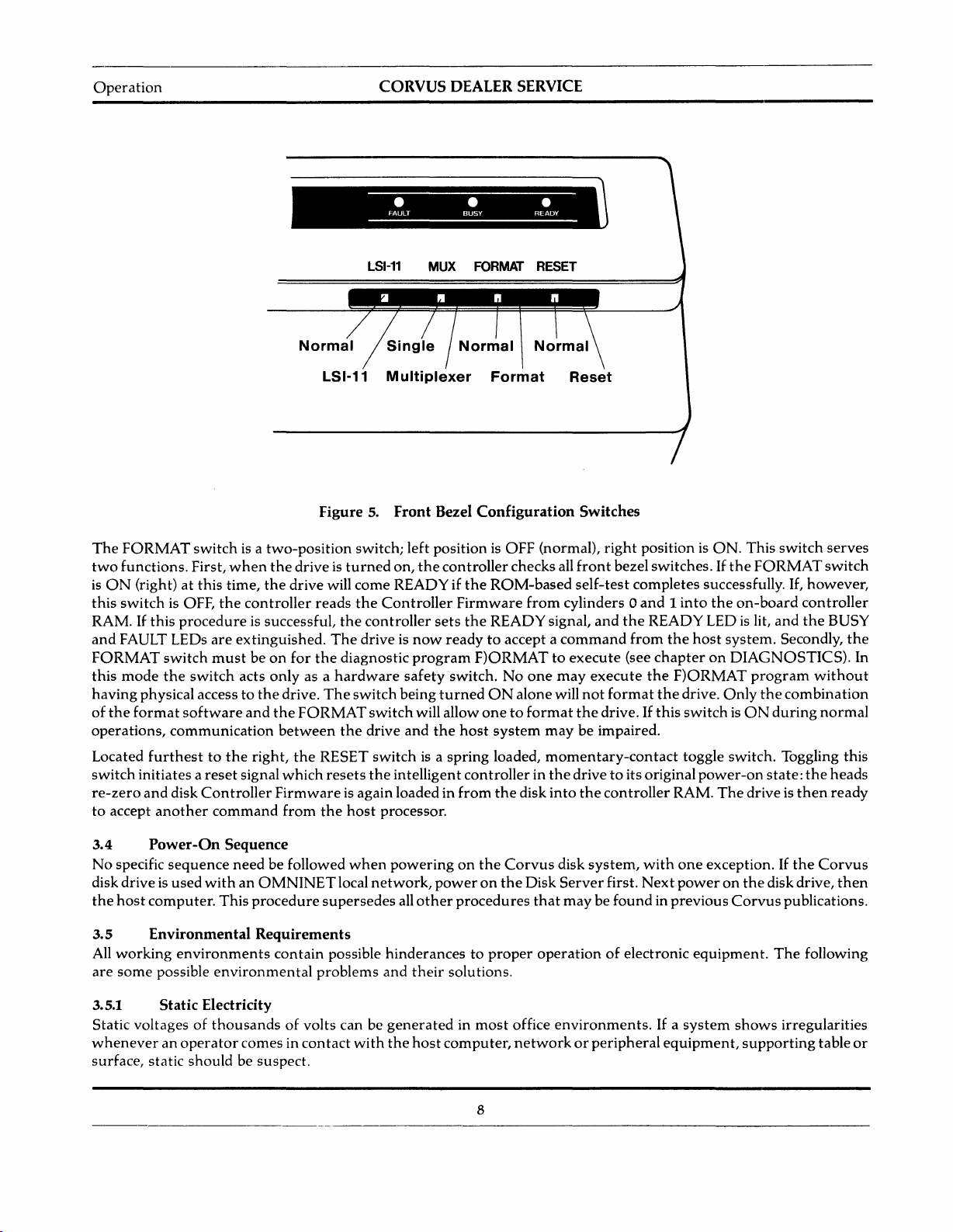
FORMAT
two
functions.
is
ON
(right)atthis
this
switch
RAM.Ifthis
and
FAULT LEOs
FORMAT
this
mode
having
of
physical accesstothe
the
format
operations,
Located
switch
re-zero
to
furthesttothe
initiates a
and
accept
another
switch
is a
First,
when
time,
is OFF,
the
controller
procedure
are
extinguished.
switch
the
mustbeon
switch
acts
software
communication
reset
signal
disk
Controller
command
LSI-11
LSI-11
Figure 5. Front Bezel Configuration Switches
two-position
the
driveisturned
the
drive will
is successful,
for
only
as a
drive.
and
the
FORMAT
between
right,
the
which
switch; left positionisOFF (norma!),
come
reads
the
Controller
the
controller
The
drive is
the
diagnostic
hardware
The
switch
switch
the
drive
RESET
resets
switchisa
the
Firmwareisagain loadedin
from
the
host
processor.
MUX
Multiplexer
on,
the
controller
READY if
sets
now
readytoaccept a
program
safety
switch.Noone
being
turned
will allow
and
the
spring
intelligent
Format
Reset
checks all
the
ROM-based
Firmware
the
from
READY
cylinders 0
signal,
command
F)ORMATtoexecute
may
ON
alonewill
onetoformat
host
system
loaded,
maybeimpaired.
momentary-contact
controllerinthe
from
the
disk
into
right
position is
front
bezelswitches.Ifthe
self-test
completes successfully. If,
and1into
and
the
READY LED
from
the
(see
chapteronDIAGNOSTICS).
execute
not
the
the
format
the
drive.Ifthis
F)ORMAT
drive.
switchisON
toggle switch. Toggling this
drivetoits original
the
controller
RAM.
ON.
the
on-board
host
system.
Only
power-on
The
This
switch
FORMAT
is
lit,
and
program
the
during
state:
drive is
serves
switch
however,
controller
the
BUSY
Secondly,
without
combination
normal
the
heads
then
ready
the
In
3.4
No
disk driveisused
the
3.5
All
are
3.5.1 Static Electricity
Power-On
specific
sequence
Sequence
need
be followed
withanOMNINET
host
computer.
This
procedure
Environmental Requirements
working
some
environments
possible
environmental
contain
when
local
supersedes
possible
problems
Static voltagesofthousandsofvolts can be
wheneveranoperator
surface, static
should
comes in
be suspect.
contact
with
poweringonthe
network,
poweronthe
all
other
procedures
hinderancestoproper
and
their
solutions.
generatedinmost
the
host
computer,
8
Corvus
disk
system,
Disk
Server
that
first.
maybefoundinprevious
operationofelectronic
office
environments.Ifa
networkorperipheral
with
one
Next
poweronthe
system
equipment,
exception.Ifthe
disk drive,
Corvus
equipment.
The
shows
supporting
Corvus
then
publications.
following
irregularities
table
or

CORVUS DEALER SERVICE
Operation
Staticismost
humidity
humidity
3.5.2
easily
helps
prevent
is70percent
Line Noise
Electrical noiseonthe
and
dropouts
Located in
power
If
line. Also,
powerissuspect,
devicesonthe
voltage
as well as low line voltage
the
CORCOM
the
the
same
regulatororisolation
effectofline voltage
the
Corvus
and
uninterrupted
3.5.3
Althoughinmost
drive
Corvus
3.6
Inherentinthe
maintenance.
field-serviceable
drive
from
cooling
equipment,
power
Temperature
environments,
must
operate
disk
within
is15degrees
Periodic Maintenance
designofthe
The
sealed disk
components.
Since contamination
removing the cover
generated
in a cool and
dry
enviromnent,
static electricity buildup,
some
typeofhumidifying device can be helpful. Ideal relative
to75percent.
power
lineisa
power
power
supplyiscapableofhandling
problem
circuit,orpoor
transformerinthe
fluctuationsonthe
line noisecaused by
elevators, etc.
major
selection
may
lie in
external
causeofinconsistent
are
just
someofthe
unitisa line filter capableofhandling
dropoutsofuptothree
poor
continuityofthe
supplytothe
Corvus
other
To
lessen
power
drive, while
high-loadelectrical
circuit.
the
building.
impact
supply (UPS)isrecommended.
the
disk drive needsnoactual
(see"Specification"atbeginningofthis manual).
fahrenheit
Winchester
per
hour.
technologydisk devices, is
mechanismofthe
Corvus
CAUTION:
of
the atmosphere In the mechanism necessitates replacementofthe unit,
to
the sealed mechanism voids all warranties.
usually associated
equipment
common
causesofdrive malfunction.
with
operation. Voltage spikes,
most
complete
building wiring, noisyorhigh
Power
The
constant
the
isolation
equipment
of
warm-up
the
disk drive requires
can be improved by including a
voltage
transformer
such
frequent
freedom
power
time,
The
temperature
there
from
no
cold weather. Since increased
"brownouts"
minor
electrical noiseonthe
power
cycles.
power-consumption
constant
regulator
will beeffective in
as photocopy machines,
interruption,
are
the
maintenance,
will help minimize
temperature
change
need
for
regular
maximum
and
the
useofan
limits
preventive
contains
protecting
heating
that
for
the
the
the
no
3.6.1 Regular Checks
Power
opened,
adjustment
Duetoslight oxidation build-uponcable
supplyvoltages will
check
the
power
procedures).
change
with
time,
and
supply voltagestoverify
connectors
socketed controller ICs periodically will also help
should
that
and
insure
bechecked periodically. Each
they
are
within
IC pins,
specified tolerances (refertochapter
reseating
the
flatcable
reliability.
9
time
the
and
Corvus
power
drivecabinet
connectors
is
7 for
and
 Loading...