

CORVUS 7100-04702 Service Manual
THE CORVUS SERVICE
MANUAL
Floppy
**.
CORVUS SYSTEMS
* •
Disk
Drive

DISCLAIMER OF ALL WARRANTIES & LIABILITIES
Corvus
manualorwith
chantability,orfitness for any particular purpose.
licensed lias is:' The entire risk as to its qualityorperformance is with
Systems, Inc., its distributor,orits retailer. The
servicing, repair,orcorrection
Corvus
Corvus
consequential damages, so
Every effort
servicing of
ware along
material after the date of publication,
errorsoromissions.
Systems, Inc. makesnowarranties, either expressedorimplied, with respect to this
respect to
Systems, Inc.beliable for direct, indirect, incidentalorconsequential damages,
Systems, Inc.
has
been
Corvus
with
future products,
the
software described in this manual, its quality, performance, mer-
and
any incidentalorconsequential damages. Innoevent
has
been
advised of
the
above limitation
madetoinsure
products. However,
Corvus
the
that this
duetothe
Systems, Inc.
nor
can
Corvus
buyer
possibility of
may
not
manual
ongoing modification
Corvus
Systems, Inc. software is sold
assumes
such
apply
accurately
cannot
guarantee
Systems, Inc. accept responsibility for
the
buyer
and
not
Corvus
the entire cost of all necessary
even
damages.
to you.
documents
Some
the
and
updateofthe
the
accuracy of
statesdonot
operation
printed
soft-
NOTICE
Corvus
ual at any time
and
This manual is copyrighted
ment
any electronic
Corvus
Copyright© 1982byCorvus
Mirror®
Logicalc,""
Workstation,"" Tap
of
Systems, Inc. reserves
without
maybepurchasedbywriting to:
Corvus
2029 O'Toole Avenue
San Jose, CA 95131
Telephone: (408) 946-7700
TWX
may
Corvus
Systems, Inc.
not,inwholeorin
medium
Systems, Inc.
patent
pending, The
Time Travel Editing,""
Systems, Inc.
notice. Revised manuals
910-338-0226
Box,""
the
and
partbecopied, photocopied, reproduced, translatedorreduced
or
machine readable form
Systems, Inc. All rights reserved.
Passive Tap
right to make changes in the
and
update
contains proprietary information. All rights reserved. This docu-
without
Corvus
EdWord,""
Concept,"" Transporter,""
Constellation,"" Corvus,""
Box,""
Active Junction
product
sheets willbepublishedasneeded
prior
Corvus
Box,""
Omninet
describedinthis man-
consent, in writing, from
Corvus
OMNINET,TM
Systems,"" Personal
Unit""
are
Corvus
trademarks
FCC WARNING
This
equipment
used
in accordance
tions. As temporarily
limits for Class A
designedtoprovide
mentina residential area is likely to cause interferenceinwhich case the
expense willberequired to take whatever measures mayberequired to correct the interference.
generates, uses,
with
the
permittedbyregulation it has
computing
reasonable protection against
and
can radiate radio frequency
instruction manual,
devices
pursuanttoSubpart
energy
may
cause interference to radio communica-
not
been
tested for compliance with
J of
Part
such
interference.
andifnot
15 of FCC Rules, which
Operation
installed
of this equip-
user
at his
own
or
will
if
and
to
and
the
are
CORVUS DEALER SERVICE
CONCEPT
CORVUS
PERSONAL
8"
FLOPPY
SERVICE
SYSTEMS
WORKSTATION
DRIVE
MANUAL
PART NO.: 7100-04702
DOCUMENT
RELEASE DATE:
This
document
CAUTION,
procedure.
care
shouldbetakentoavoid this.
service technicionoroperator
NO.: CCC/12-01/1.1
JULY
10, 1983
contains
and
WARNING.
The
CAUTION indicates
three
typesofnotations.
The
NOTE
indicates
that
potential
The
WARNING indicates
exists,
and
extreme
These
are,inincreasing
some
actiontobe
damagetothe
care should be
orderofimportance,
takentospeedorsimplify a
equipmentoruser
that
potential
takentoavoid these.
harmorinjurytothe
data
NOTE,
exists,
and
CORVUS
DEALER SERVICE
TABLE
OF
CONTENTS
CORVUS
DEALER
SERVICE
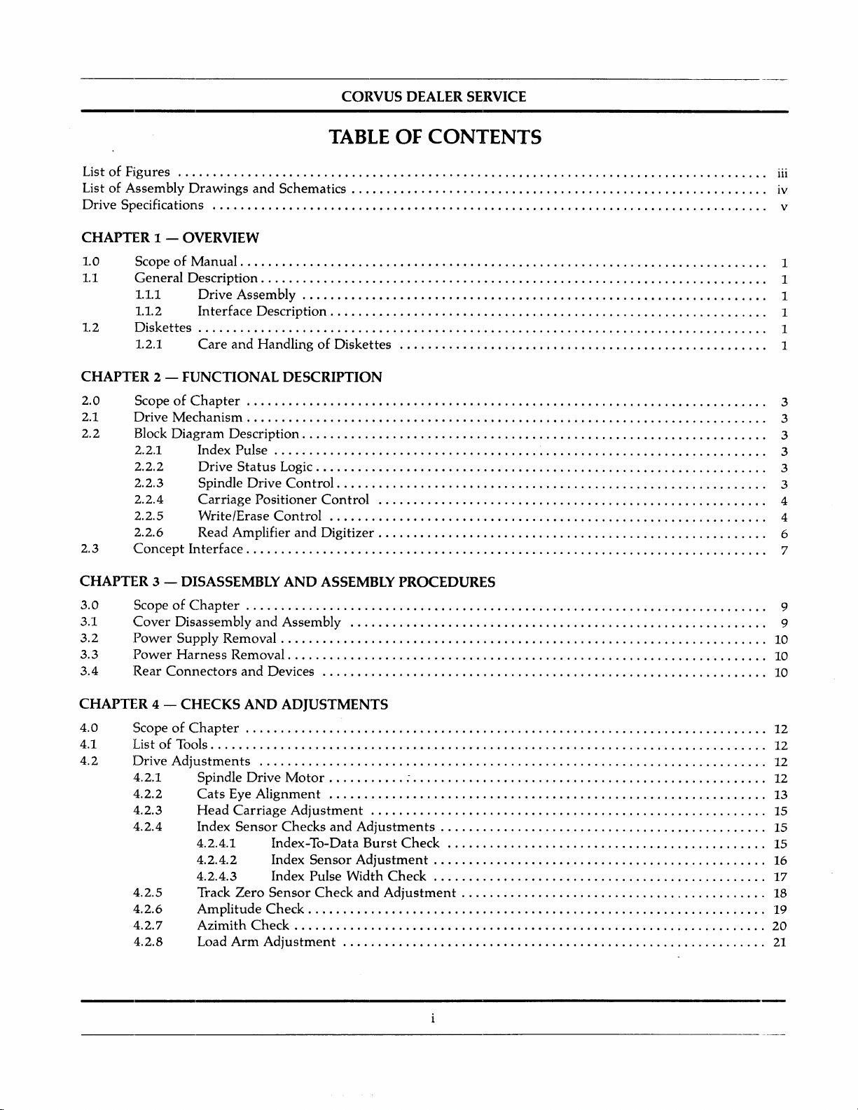
TABLE
OF
CONTENTS
ListofFigures
ListofAssembly
Drawings
and
Schematics . . . . . . . . . . . . . . . . . . . . . . . . . . . . . . . . . . . . . . . . . . . . . . . . . . . . . . . . . .
..
Drive Specifications V
CHAPTER
1.0
1.1
1.2
CHAPTER
2.0
2.1
2.2
2.3
1 -
OVERVIEW
ScopeofManual.
General
1.1.1
1.1.2
Description.
Drive
Interface
Diskettes
1.2.1
2 - FUNCTIONAL DESCRIPTION
Care
. . . . . . . . . . . . . . . . . . . . . . . . . . . . . . . . . . . . . . . . . . . . . . . . . . . . . . . . . . . . .... . . . . . . . . .
. . . . . . . . . . . . . . . . . . . . . . . . . . . . . . . . . . . . . . . . . . . . . . . . . . . . . . . . . . . . . . . . . . . . . .
Assembly.
Description.
. . . . . . . . . . . . . . . . . . . . . . . . . . . . . . . . . . . . . .... . . . . . . . . . . . . . . . . . . . . . . .
. . . . . . . . . . . . . . . . . . . . . . . . . . . . . . . . . . . . . . . . . . . . . . . . . . . . . . . . . . . .
. . . . . . . . . . . . . . . . . . . . . . . . . . . . . . . . .
and
HandlingofDiskettes 1
ScopeofC:hapter . . . . . . . . . . . . . . . . . . . . . . . . . . . . . . . . . . . . . . . . . . . . . . . . . . . . . . . . . . . . . . . . . . . . . . . . .
Drive
Mechanism.
Block
Diagram
2.2.1
2.2.2
2.2.3
2.2.4
2.2.5
2.2.6
Concept
Index Pulse
Drive
Spindle
Carriage
Write/Erase
Read Amplifier
Interface.
. . . . . . . . . . . . . . . . . . . . . . . . . . . . . . . . . . . . . . . . . . . . . . . . . . . . . . . . . . . . . . . . . . . . . . . .
Description.
Status
Drive
Positioner
. . . . . . . . . . . . . .... . . . . . . . . . . . . .... . . . . . . . . . . . . . . . . . .... . . . . . . . . . .
.....
. . . . . . . . . . . . . . . . . . . . . . . . . . . . . . . . . . . . . . . . . . . . . . . . . . . . . . . . . . . . . . . .
Logic. . . . . . . . . . . . . . . . . . . . . . . . . . . . . . . . . . . . . . . . . . . . . . . . . . . . . . . . . . . . . . .
Control.
. . . . . . . . . . . . . . . . . . . . . .... . . . . . . . . . . . . . . . . . . . . . . . . . . . . . . . . . .
Control
Control
and
Digitizer.
. . . . . . . . . . . . . . . . . . . . . . . . . . . . . . . . . . . . . . . . . . . . . . . . . . . . .
. . . . . . . . . . . . . . . . . . . . . . . . . . . . . . . . . . . . . . . . . . . . . . . . . . . . . . . . . . . . . . . . . . . . . . . .
..
..
..
..
..
..
..
..
..
..
..
..
..
iii
IV
1
1
1
1
1
3
3
3
3
3
3
4
4
6
7
CHAPTER
3.0
3.1
3.2
3.3
3.4
ScopeofC:hapter . . . . . . . . . . . . . . . . . . . . . . . . . . . . . . . . . . . . . . . . . . . . . . . . . . . . . . . . . . . . . . . . . . . . . . . . .
Cover
:Power Supply Removal
:Power
:Rear ConIlectors
CHAPTER
4.0
4.1
4.2
ScopeofC:hapter
ListofTools
Drive
4.2.1
4.2.2
4.2.3
4.2.4
4.2.5
4.2.6
4.2.7
4.2.8
3 -
DISASSEMBLY
Disassembly
Harness
4 -
CHECKS
Adjustments
Spindle
Cats
Head
Index
4.2.4.1
4.2.4.2
4.2.4.3
Track
Amplitude
Azimith
Load
AND
ASSEMBLY
and
Assembly 9
Removal
and
Devices
AND ADJUSTMENTS
Drive
Motor
Eye
Alignment
Carriage
Sensor
Zero
Arm
Adjustment
Checks
and
Index-To-Data
Index
Sensor
Index Pulse Width
Sensor
Check
Check
Check
Adjustment
PROCEDURES
-. . . . . . . . . . . . . . . . . . . . . . . . . . . . . . . . . . . . . . . . . . . . . . . . .
Adjustments
Burst
Check
Adjustment
Check
and
Adjustment
..
9
10
10
10
12
12
12
..
12
13
15
15
15
16
17
18
19
20
21

CORVUS
DEALER
SERVICE
4.3
4.4
CHAPTER
5.0 Scope
5.1 Diagnostics
5.2
5.3
5.4
5.5
Interface
4.3.1
4.3.2
4.3.3
Power
Supply
5 - TROUBLESHOOTING
of
5.1.1
5.1.2 Test
System
5.2.1
5.2.2
5.2.3
Floppy
5.3.1
5.3.2
5.3.3
Level
Drive
Interface
Troubleshooting
APPENDICES
Appendix A
Appendix B
Appendix C
Appendix D
Glossary.
Part
Schematic
Assembly
Controller
Bias Voltage
Range
Adjustment
Pre
com
p
Adjustments
Chapter
Operation
Descriptions
Troubleshooting.
Interface
Floppy
Drive
Concept
Unit
Power
Supply
Diskette
Power
Harness
Controller
Guide
Numbers
Drawings.
Checks
and
Adjustments
Adjustment
~ ~
. . . . . . . . . . . . . . . . . . . . . . . . . . . . . . . . . . . . . . . . . . . . . . . . . . . . . . . . . . . . .
Controller
and
Cable
Workstation
Drive
Unit
;
Card
. . . . . . . . . . . . . . . . . . . . . . . . . . . . . . . . . . . . . . . . . . . . . . . . . . . . . . . . . . . . . . . . . . . .
. . . . . . . . . . . . . . . . . . . . . . . . . . . . . . . . . . . . . . . . . . . . . . . . . . . . . . . . . . . . . . . . . . . . . . . .
. . . . . . . . . . . . . . . . . . . . . . . . . . . . . . . . . . . . . . . . . . . . . . . . . . . . . . . . . . . . . . . . . . . .
Diagrams
. . . . . . . . . . . . . . . . . . . . . . . . . . . . . . . . . . . . . . . . . . . . . . . . . . . . . . . . . . . . . .
21
22
22
22
23
24
24
24
24
..
25
26
26
26
26
26
27
27
27
..
28
..
30
..
31
32
..
38
ii

CORVUS DEALER SERVICE
LIST
OF
FIGURES
CORVUS DEALER SERVICE
LIST
2-1 FunctioIlal Block Diagram 4
2-2
2-3
2-4
3-1
3-2
3-3
4-1 Drive Circuit Board Assembly, Test Points
4-2
4-3
4-4
4-5
4-6
4-7
4-8
4-9
4-10 Head
4-11 Head
4-12
4-13
4-14
5-1 Floppy
5-2
FM Recording Magnetization
Write
Operation
Read Timing
Cover
Installation 9
Drive
Power
Left
Cover
Hub
Center
Cats
Eye
Pattern
Timing Diagram 6
Diagram.
Connector
Line
and
Track Locations
Head Module Retaining and
Index-to-Data
Index
Sensor
Burst
Retaining Screws
Profiles.
. . . . . . . . . .... . . . . . . . . .... . . . . . . . . . . . . . . . . . . . . . . . . . . . . . . . . . . . . . . . . . .
Cam
Screws
and
Negative Going Pulse Width . . . . . . . . . . . . . . . . . . . . . . . . . . . . . . . . . . . . . . . . . . . . . . . . . . . . . . . . . . . . . .
Track00Sensor
Optimum
Azimuth
Azimuth
Load
Arm
Interface
Power
Controller
Supply
[)rive
Interface
Controller
Head
Adjustment
Azimuth
. . . . . . . . . . . . . . . . . . . . . . . . . . . . . . . . . . . . . . . . . . . . . . . . . . . . . . . . . . . . . .
Alignment
Acceptable Lower Limit
Acceptable Upper Limit " 21
Adjustment,
Front
View 21
Card
Adjustments
Installation
Installation
OF
FIGURES
. . . . . . . . . . . . . . . . . . . . . . . . . . . . . . . . . . . . . . . . . .... . . . . . . . .
Adjustment
. . . . . . . . . . . . . . . . . . . . . . . . . . . . . . . . . . . . . . . . . . . . .
..
..
..
..
..
20
20
22
23
25
26
5
7
10
11
13
13
14
15
16
17
18
18
iii

CORVUS DEALER SERVICE
LIST OF ASSEMBLY DRAWINGS
AND
SCHEMATICS
CORVUS DEALER SERVICE
'LIST
Drive Schematics. . . . . . . . . . . . . . . . . . . . . . . . . . . . . . . . . . . . . . . . . . . . . . . . . . . . . . . . . . . . . . . .. . . . . . . . . . . . . . . . .
Controller
Schematic
OF
ASSEMBLY
DRAWINGS
AND
SCHEMATICS
Assembly Drawings
Mechanism.
Power
Left
Cover
DC
Cable 41
Logic Board
Floppy
. . . . . . . . . . . . . . . . . . . . . . . . . . . . . . . . . . . . . . . . . . . . . . . . . . . . . . . . . . . . . . . . . . . . . . . . . . . . . . . . . . . . .
Supply.
Controller
. . . . . . . . . . . . . . . . . . . . . . . . . . . . . . . . . . . . . . . . . . . . . . . . . . . . . . . . . . . . . . . . . . . . . . . . . . . . . . . . . . .
0 • • • • • • • • • • • • • • • • • • • • • • • • • • • • • • • • • • • • • • •
..
32
37
..
38
..
39
••
40
42
43
iv
CORVUS DEALER SERVICE
SPECIFICATI()NS
CORVUS
DEALER
SERVICE
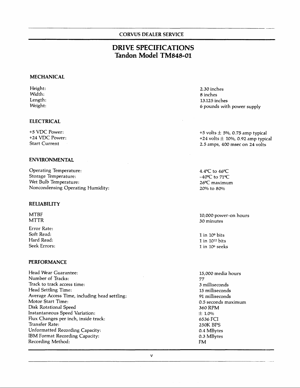
MECHANICAL
Height:
Width:
Length:
Weight:
ELECTRICAL
+5
VDC
Power:
+24
VDC
Power:
Start
Current
ENVIRONMENTAL
Operating
Storage
Wet Bulb
Noncondensing
Temperature:
Temperature:
Temperature:
Operating
Humidity:
DRIVE
SPECIFICATIONS
Tandon Model TM848-01
2.30 inches
8 inches
13.125 inches
6
pounds
+5 volts ± 5%, 0.75
+24
2.5
4.4°Cto46°C
-40°Cto71°C
26°C
20%to80%
with
vo~ts
± 10%, 0.92
amps,
400
maximum
power
msecon24
supply
amp
amp
typical
typical
volts
RELIABILITY
MTBF
MTTR
Error
Rate:
Soft
Read:
Hard
Read:
Seek
Errors:
PERFORMANCE
Head
Wear
Guarantee:
NumberofTracks:
Track
to
track
access time:
Head
Settling
Average
Motor
Disk
Instantaneous
Flux
Transfer
Unformatted
IBM
Recording
Start
Rotational
Changes
Format
Time:
Access Time, including
Time:
Speed
Speed Variation:
per
Rate:
Recording Capacity:
Recording Capacity:
Method:
head
inch, inside track:
settling:
10,000
30
1in109bits
1
1 in 10
15,000 media
77
3 milliseconds
15 milliseconds
91
0.5 seconds
360
power-on
minutes
in
1012bits
6
seeks
milliseconds
RPM
maximum
± 1.0%
6536
FCI
250K BPS
MBytes
0.4
0.3
MBytes
FM
hours
hours
v
CORVUS DEALER SERVICE
CHAPTER
OVERVIEW
1
CORVUS DEALER SERVICE
1.0
This
Disk
procedure.
shouldbereturnedtoCorvus
All
in a
This
1.1 General Description
The
Workstation.
interfaceiscomposedofa single
base
1.1.1 Drive Assembly
The
Corvus
All electronic
the
mountedtothe
Scope of Manual
manualisdesigned
Drive
and
the
Except
information
separate
first
Corvus
unit.
mechanism
Systems
drive
in this
manualoraddendum.
chapter
cabinetisthe
will briefly describe
Floppy
The
floppy is a Single-sided, single-density drive
and
andisincorporatedinthe
componentsofthe
floppy chassis assembly.
for
interface. A
for
the
power
manual
Disk
Drive
internal
power
service technicians
electronics
CHAPTER
OVERVIEW
who
troubleshooting
supply,
via a
appliestothe
providesanadditional
Interface
drive
receptacle,
the
Return
the
are
are
mountedona single circuit
guideisincluded
internal
Merchandise
single-sided,
drive,
the
Controller
manufacturedbyTandon
drive cabinet.
fuse
holder,
perform
partsofthe
Authorization
single-density
interface,
data
storage
Card
and
on/off
1
maintenanceorwarranty
which
drive
and
which
a cable.
switch,
will direct
are
not
(RMA).
drive only.
the
diskettes.
and
boot
device
uses
eight-inch
The
card
Corporation™.
board
locatedinthe
and
interface
the
replaceable. In
Subsequent
for
plugs
connectors.
serviceonthe
techniciantothe
such
models will be
the
Corvus
standard
into
slot
The
power
drive's chassis.Atthe
Concept
floppy diskettes.
threeofthe
supplyis
The
Corvus
appropriate
cases,
provided
power
Floppy
the
drive
covered
Personal
The
Concept
rear
supply
by
of
is
1.1.2 Interface Description
The
floppy
fifty-pin
associatedcircuits.
included).
The
Interface
adjustments
1.2 Diskettes
The
floppy
diskette
For
be
turned
diskette
The
floppy
has a slot
mustbecoveredtowriteonthe
1.2.1 Care and Handling of Diskettes
Itisimportant
maintained.Adamagedorcontaminated
the
read/write
interfaceiscomposedofan
twisted
Data
counterclockwise,tothe
leveristurned
cutinthe
pair
cable,
which
Data
transfers
transfers
Controller
willbecoveredinChapter
operates
insertion,
driveisequipped
that
headsofthe
between
Card
with
standard
operator
clockwise,
with
protective
the
diskettebecared
drive.
Interface
is acceptable.
between
the
Controller
has
three
Four.
eight-inch, single-sided, single density,
accessisprovided
straight-up
until
perpendicular
a Write
jacket.
When
diskette.
for,
Controller
the
drive
and
adjustment
via a
position,
Protect
diskette
Sensor.
the
slotisUNCOVERED,
handled,
can
Card
The
Controller
and
the
Controller
the
Concept
potentiometers:
slot
locatedonthe
for
diskette
with
the
door,
This
sensor
and
stored
impairorprevent
and
a fifty-pin flat
usesanintelligent Floppy
areinthe
are
eight-bit
bias voltage,
soft-sectored
frontofthe
loading.
and
operatesinconjunction
properlysothat
Once
the
disketteisnow
the
disketteiswrite
recoveryofdata,
ribbon
formofraw
parallel.
range,
drive.
the
the
integrityofthe
cable.
Some
Controller
serial
data
and
precomp
diskettes.
The
Diskette
disketteisfully
loaded.
with
the
PROTECTED.
recorded
and
can
resultindamage
drives
chip
(clock pulses
adjust.
Lever
inserted,
diskette
The
use
and
These
must
the
which
slot
data
a
is
to
T1'Tandon
is a
trademarkofTandon
Corporation
1

Overview
CORVUS DEALER SERVICE
Following
1) Keep
2) Keep diskettes in
3)
4)
these
the
Do
not
bendorfold
Store
diskettesatroom
guide
diskettes
liquids.
5)
REMOVE
DISKETTES
can cause noisetobe
Floppy
recommended
diskettes
haveanoperating
that
lines will increase
away
from
their
protective
the
diskettes. Be
temperatures
BEFORE
writtenonthe
back-up
copiesofall valuable
diskette
magnetic
jackets
careful
POWERING
diskette
in a
fields.
when
covered
reliability
Don't
not
when
ON
and
renderitunusable.
lifeofabout40hours.
databekept
and
place
in use.
inserting
container
OR
OFF
This
time
in a safe place.
extend
the
lifeofthe
diskettes:
diskettesontelevisionsormonitors.
Never
touch
the
them
away
THE
varies
precision
into
the
drive.
from
contamination
DRIVE.
Random
dependingonenvironment
surfaceofthe
suchassmokeorspilled
spikes
during
diskettes.
poweronor
and
usage. It is
off
2
CORVUS DEALER SERVICE
CHAPTER 2
FUNCTIONAL DESCRIPTION
CORVUS DEALER SERVICE
CHAPTER 2
FUNCTIONAL DESCRIPTION
Functional
Description
2.0
This
Controller.
2.1 Drive Mechanism
The
The
ejector.
clampingofthe
brushless
The
electronics.
disketteisinserted
Protect
When
to
increasing
Data
circuits.
In
1.
2.
3.
ScopeofChapter
chapter
drive
disketteisaccurately
headispositioned
performingawrite
0.012
recovery
addition,
A
track00sensor
The
The
diskette.
will
describe
The
electronics will be
consistsofa spindle drive
Closing
status
inch
two
Write
the
diskettetothe
DC
motor.
The
stepper
output
(nominal).
the
space
electronics include a low-level
the
drive
index
sensors,
Protect
diskette
The
over
into
signal is availabletothe
between
has
that
sensor
the
functional
positioned
lever
drive
head
is loaded
the
motor
the
rotates
drive,
operation,
Tunnel
the
the
following
senses
eachofwhich
disables
operationofthe
presentedata block
system,ahead
when
inserted
activates
hub.
desired
the
a 0.013-inch
erasing
tracks.
when
the
cone
The
drive
into
contact
trackbymeansofa
3.6
degreestocauseaone-track
Write
Protect
interface.
wide
helps
prevent
head
sensors:
the
Head
consistsofan
the
write
Drive
Mechanism,
diagram
positioning
by plasticguides.
and
hubisdrivenata
with
the
Sensor
(nominal)
crosstalk
amplifier, a differentiator, a
Carriage
LED light
electronics
level.
system,
clamp
recording
stepper
disables
data
Assembly
whenever
andaread/write/erase
The
positionisensuredbythe
system,
between
resultingincenteringofthe
constant
medium
motor
linear
the
write
trackisrecorded.
is positionedatTrack 00.
source
andaphototransistor.
the
Drive
Electronics,
speedof360
whenever
and
band
movement.
electronicsofthe
tracksbyerasing
zero
write-enable
RPM
the
assembly
This
trackisthen
crossing
Whenawrite-protected
tabisremoved
system.
backstop
by a
servo-controlled
diskette
and
drive,
the
outer
detector,
and
Interface
and
diskette
lever
is latched.
its associated
and
a Write
tunnel
and
erased
edges
digitizing
from
disk
and
and
the
2.2
Figure
The
1) Index Pulse
2)
3)
2.2.1 Index Pulse
An
LED, a
phototransistor,
phototransistorispassedonto
presentedonthe
2.2.2
There
2.2.3
The
motor/tachometer.
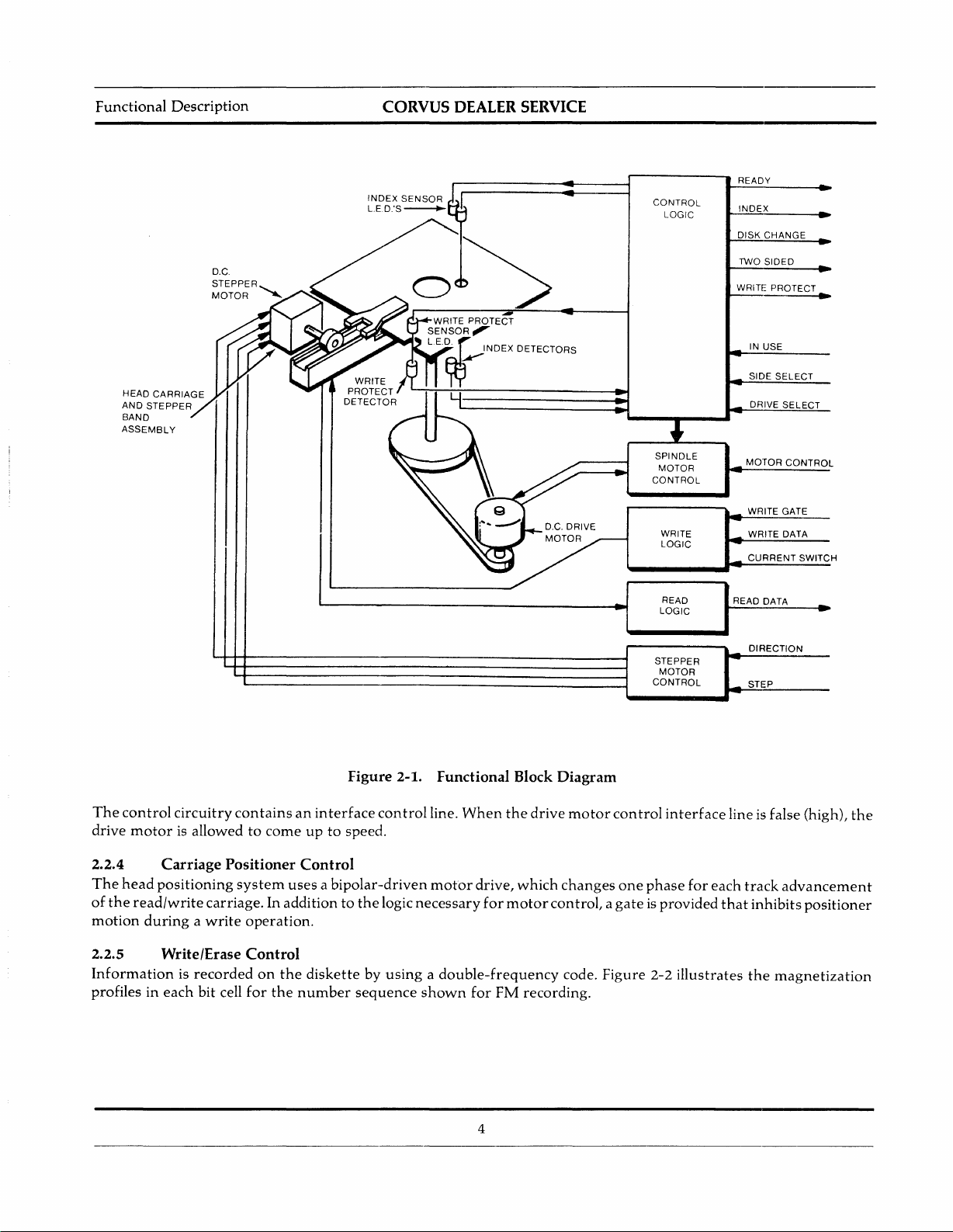
Block Diagram Description
2-1 is a
drive
Drive
Spindle
index pulse is
functional
consistsofsix
Shaper
Status
phototransistor,
Logic
Drive
Control
providedtothe
light
index
block
from
pulse
Drive Status Logic
are
five
status
logic lines:
Spindle Drive Control
spindle drive
system
The
servo
functional
andapulse
diagramofthe
groups:
Controller
the
LED
strikes
the
pulse
interface
Write
Protect,
consists
electronics
of
drive.Itshouldbereferredtoin
Carriage
4)
Write/Erase
5)
Read
6)
via
the
index pulse
shaping
shaping
line.
a spindle
are
network.
the
phototransistor,
network,
Track00Sensor, Two-Sided Disk, Ready, Disk
assembly
locatedonthe
As
which
printed
3
interface
the
producesapulse
driven
Position
Control
Amplifier
line.
index
causingitto
hole in
through
circuit board.
conjunction
Control
and
The
index
conduct.
for
a drive belt by a
with
Digitizer
circuitry
the
disk passes
each
The
hole
Change
the
following sections.
consistsofan
an
index LED-
signal
from
the
detected.
This
(see
section
brushless
index
index
pulse
2.3).
is
DC
Functional
Description
CORVUS DEALER SERVICE
The
control
drive
2.2.4
The
head
of
the
motion
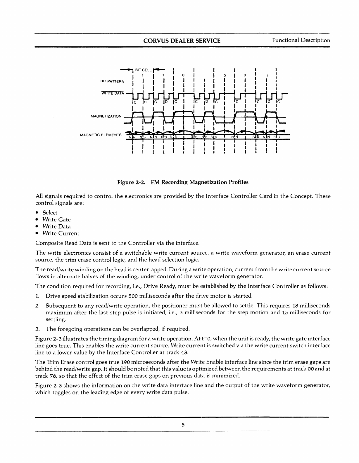
2.2.5
Informationisrecordedonthe
profilesineach
circuitry
motor
is allowedtocomeupto
Carriage
positioning
read/write
duringawrite
containsaninterface
Positioner
carriage. In additiontothe
Write/Erase
bit cell
system
operation.
Control
for
the
Figure
speed.
2-1.
control
Functional Block Diagram
line.
When
the
Control
usesabipolar-driven
logic
diskettebyusingadouble-frequency
number
sequence
motor
necessary
shown
drive,
for
for
4
motor
FM
drive
motor
control
which
changes
control,agateisprovided
code.
recording.
one
Figure
interface
phase
2-2
line is false (high),
for
each
that
illustrates
track
advancement
inhibits
the
magnetization
the
positioner
CORVUS DEALER SERVICE
........,
BIT
CELL
I 1 I 1
BIT PATTERN I I
WRITE DATA I I
,.......
Functional
Description
All signals
control
requiredtocontrol
signals are:
• Select
• Write
• Write
• Write
Composite
The
source,
The
Gate
Data
Current
Read
write
electronics
the
trim
read/write
flowsinalternate
The
condition
1.
Drive
2.
Subsequenttoany
maximum
required
speed
after
settling.
3.
The
foregoing
Figure
line
linetoa
The
behind
track
Figure
which
2-3
illustrates
goes
true.
lower
Trim
Erase
the
read/write
76,
so
that
2-3
shows
togglesonthe
This
valuebythe
Dataissenttothe
consistofa
erase
control
windingonthe
halvesofthe
for
recording,
stabilization
occurs
read/write
the
last
step
operations
the
timing
enables
the
Interface
control
goes
true
gap. It
shouldbenoted
the
effectofthe
the
informationonthe
leading
edgeofevery
Figure
the
logic,
2-2.
electronics
Controller
switchable
and
the
FM
are
via
write
head
headiscentertapped.
winding,
pulse
under
controlofthe
Le.,
Drive
Ready,
500
milliseconds
operation,
the
is initiated, i.e., 3 milliseconds
canbeoverlapped, if
diagram
write
forawrite
current
source.
Controllerattrack
190
microseconds
that
trim
erase
gapsonprevious
write
data
write
Recording Magnetization Profiles
providedbythe
the
interface.
current
selection logic.
Duringawrite
mustbeestablished by
after
the
positioner
required.
operation.Att=O,
Write
currentisswitched
43.
after
the
this
valueisoptimized
interface
data
pulse.
Interface
source,awrite
operation,
write
waveform
Controller
waveform
current
generator.
the
drive
motorisstarted.
mustbeallowedtosettle.
for
the
step
when
the
unit
via
Write Enable
data
is minimized.
line
and
interface
between
the
outputofthe
the
Cardinthe
Concept.
generator,anerase
from
the
write
current
Interface
motion
is ready,
the
write
line since
Controller
This
requires18milliseconds
and15milliseconds
the
write
gate
current
the
trim
switch
erase
as follows:
requirementsattrack00and
write
waveform
generator,
These
current
source
for
interface
interface
gaps
are
at
5
Functional
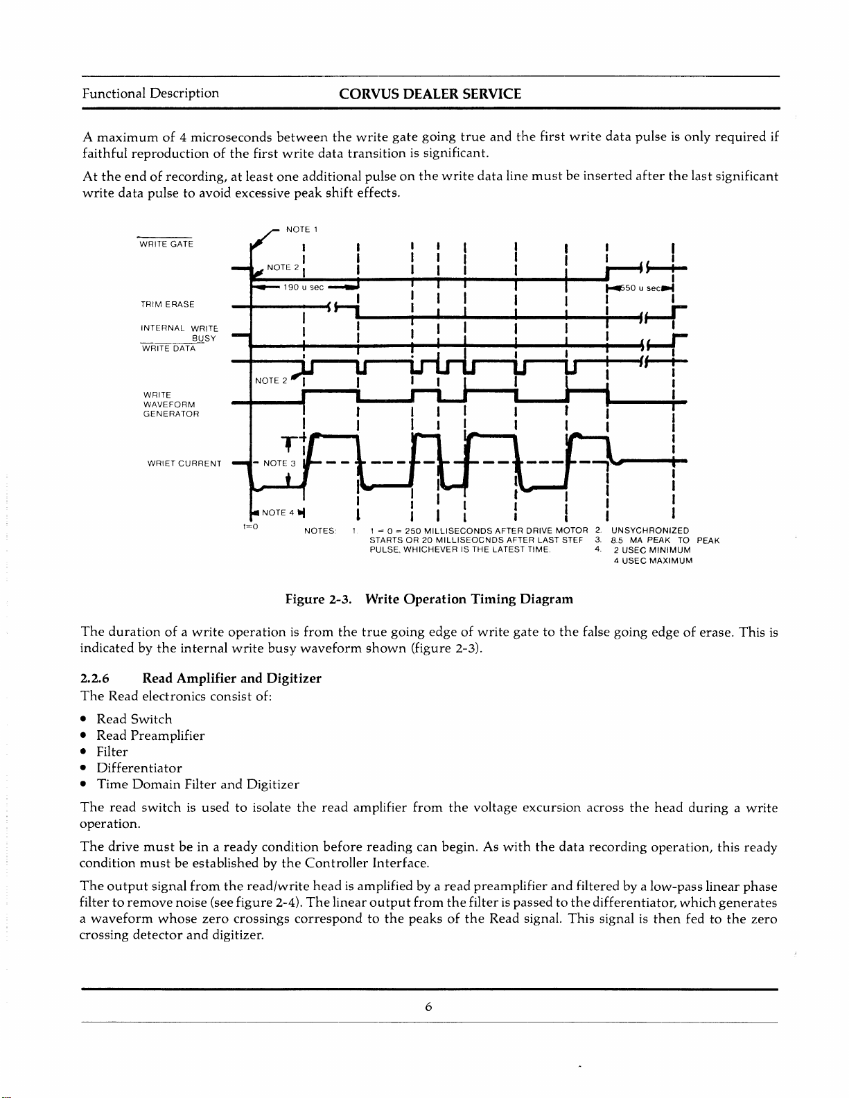
A
maximum
faithful
At
write
reproductionofthe
the
endofrecording,atleast
data
Description
of4microseconds
between
first
one
pulsetoavoid excessive
write
additional
peak
CORVUS DEALER SERVICE
the
write
gate
going
true
data
transition
shift
pulseonthe
effects.
is significant.
write
and
data
the
first
line
mustbeinserted
write
data
pulseisonly
after
the
required
last
significant
if
The
durationofa
indicated
WRITE GATE
TRIM ERASE
INTERNAL
WRITE DATA
WRITE
WAVEFORM
GENERATOR
WRIET
by
the
WRIT~
BUSY
CURRENT
write
internal
......
_-+-_-i-_--t
NOTE 2
I
Tt
Figure
operationisfrom
write
busy
waveform
~-...,..
.....i~-~-~-...jI
-~-"'---..a..-___lI~_4~
1 = 0 =
250
STARTS OR20MILLISEOCNDS
PULSE,
WHICHEVER
2-3.
Write Operation Timing Diagram
the
true
going
shown
(figure
I
MILLISECONDS
IS THE LATEST TIME.
edgeofwrite
2-3).
I
t""'--
I
I I
AFTER DRIVE
AFTER LAST STEF
gatetothe
MOTOR
...
I I
........
2.
UNSYCHRONIZED
3.
8.5 MA
4.2USEe
4
false
going
s--:...
50usec
....
H-r
I I
PEAK
MINIMUM
USEC
MAXIMUM
edgeoferase.
I
I
TO PEAK
This
is
2.2.6
The
Read
•
•
Read
Read Amplifier and Digitizer
Read electronics
Switch
Preamplifier
• Filter
•
Differentiator
•
Time
Domain
The
read
switchisusedtoisolate
operation.
The
drive
mustbein a
condition
The
mustbeestablishedbythe
output
signal
filtertoremove
a
waveform
crossing
whose
detector
Filter
from
noise
and
consist
and
ready
the
(see
zero
digitizer.
of:
Digitizer
condition
read/write
figure
2-4).
crossings
the
read
amplifier
before
Controller
reading
Interface.
headisamplifiedbya
The
linear
output
correspondtothe
from
the
can
begin. As
read
from
the
filterispassedtothe
peaksofthe
6
voltage
excursion
with
the
preamplifier
Read signal.
data
and
filteredbya
This
across
the
recording
operation,
low-pass
differentiator,
signal is
head
duringawrite
which
then
fedtothe
this
linear
generates
ready
phase
zero
 Loading...