

Page 1
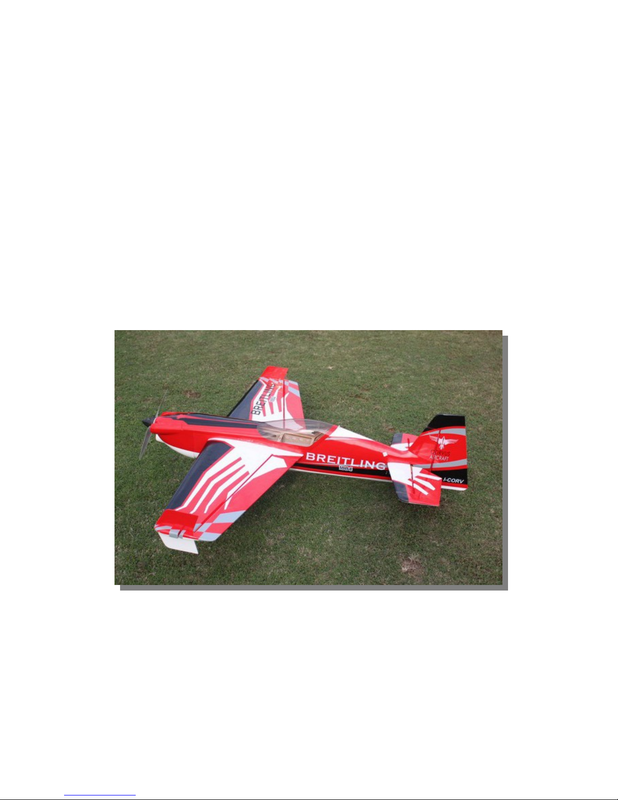
ARF® MODEL
Corvus Racer 70 Electric V2
Instruction Manual
Page 2

ARF® MODEL
Dear Customer,
Thanks for purchasing this newly designed CORVUS 70E V2 aerobatic RC airp lane. With an
approximate flying weight of 5. 5 Lbs., the new Corvus was designed for IMAC a n d fr ee style flying. It
was developed with unique appearance and extreme flight performance in mind. The new Corvus 70E
V2 was covered with genuine Monocote film, and equipped with good quality accessories, including
carbon fiber wing tube, anodized 6061 aluminum landing gear or carbon fiber landing gear as an
upgrade option. We hope you enjoy this plane as much as we d o.
The new V2 version of CORVUS 70E has the following improvements f rom previous versions:
• Control surfaces is larger than V1 version. Up to 50 degrees of throw on all control surfaces.
Best for more vibrant aerobatic flight.
• Improved wheels with more durable materials, and filled with rubb er.
• High quality cap head screws included.
• Improved ball link assembly.
• Stainless steel wheel axle.
• Newly designed fiberglass control horn assembly
• Side Force Generators (SFG) included
• Air exit opeing behind the rudder servo for electric set-ups.
• Longer tale moment improve s tr acking of the airplane, giving it rock solid precision flight.
SAFETY ISSUES OF RADIO CONTROL FLYING MODELS
With radio control aircraft, like any hobby or sport, there are certain risks. The operator of these
models is responsible for these risks. If misused or abused, you may cause serio u s bodily injury and/or
damage to property. With this in m i nd, you will want to be certain that you build your model carefully
and correctly. If you are not an experienced flier, have your work checked an d a sk for help in learning
to fly safely. This model aircraft is NOT a toy and must be operated and flow n in a safe manner at all
times. Always perform a pre-flight check of the model including all control surfaces, proper function
of the radio gear, structure, radio ra n ge, a n d a n y other area relating to the safe operation of this aircraft.
Models are not insurable but operators are. You can obtain coverage through membership in the
Academy of Model Aeronautics (AMA). For an AMA information package call 1-800-43 5-9262, ext.
292 or visit the AMA website at "www.modelaircraft.org"
Page 3

ARF® MODEL
By the act of using the final assembled model, the purchaser/operator accepts all resulting liability
ARF MODELS WARRANTY AND RETU RN P O LICY
We guarantee that the plane is in perf e ct c ondition at purchase. The warranty will be voided afte r
modifications and usages. If you have any questions or find any issues, please contact the distribu t ors
in your area. For US customers, please contact General Hobby. Their website is
www.generalhobby.com. Their phone number is 909-581-8873. Customers in other areas please
contact the sellers you purc hased it from.
Specifications and Recommended Power Setup
• Wingspan: 59"(1500mm)
• Length: 57"(1450mm)
• Wing Area: 741sq in (47.8sq dm)
• Flying Weight: 4.8-6 lbs. (2200-2700g)
Electric Power Setup:
• Hacker A40-10S with 4S 3300-4200mAh, 14x7 prop
• Hacker A40-12S with 5S 3000-3700mAh, 13x6.5 prop
• Hacker A40-12S with 4S 3300-4200mAh, 14x7 prop
• Hacker A40-14S with 5S 3000-3700mAh, 14x7 prop
• DUSKY XM5050EA-9 6S 3300-4400mAh, 15x8prop or other 1000-1200 watt, 300g class
electric motors
• ESC:70-100A
• 4 or 5 Mini size high torque servos, Hitec HS5245 or 7245 recommended
*please note that you may 1 or 2 servos for elevators
• Aircraft radio and receive of your choice, 4 channels minimum
Features and Photo Gallery
• Newly designed structure
• Aerofoil tail wings
• Two pieces removable wings
• Carbon fiber wing tube
• PVC canopy
Page 4

ARF® MODEL
• Larger ailerons and elevator designed for extreme 3D aerobatic flying
• Air exit opeing for cooling
• Side Force Generator’s (SFG) Included
• Canopy extended into cowl for easier battery access
Page 5
ARF® MODEL
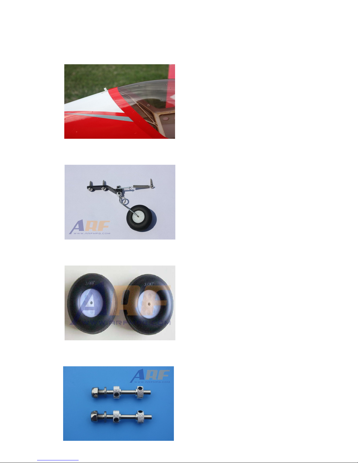
• Quick release canopy latch
• Light weight C.F. tail wheel assembly
• High-quality durable rubber wheels
• Improved new wheel axle (stainless steel)
Page 6
ARF® MODEL
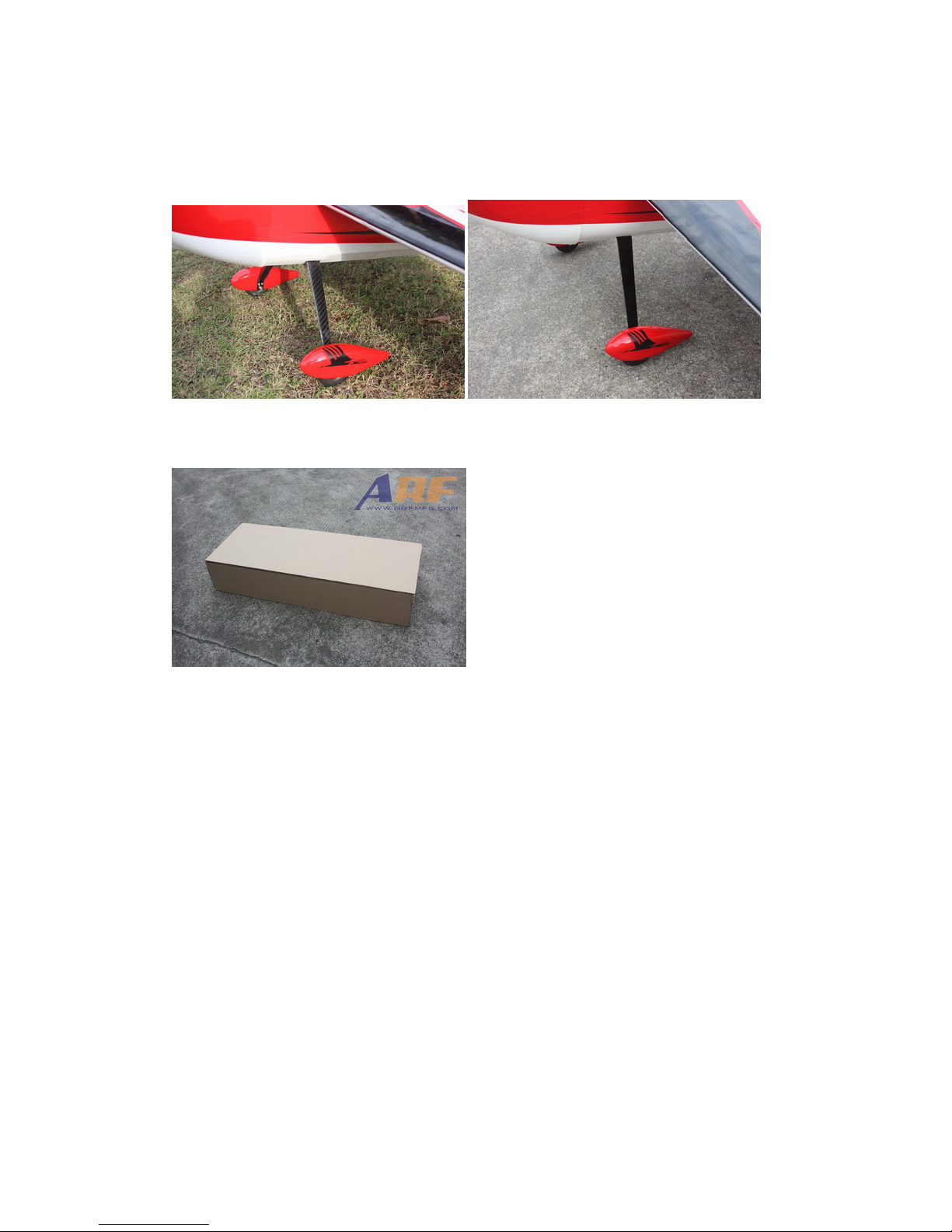
• Landing gear options : a nodized 6061 Aluminum or carbon fiber
*Carbon fiber *Anodized 6061 aluminum
• Honeycomb Board carton packing for safer transportation
Page 7
ARF® MODEL
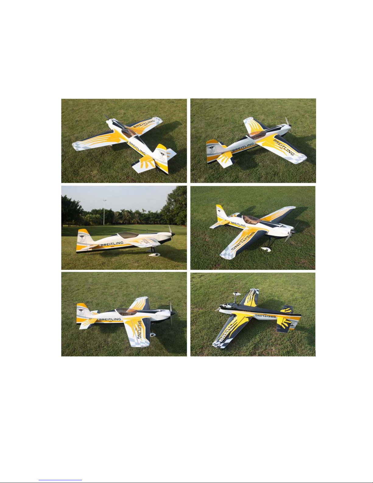
Scheme A: white/yellow/black
Page 8

ARF® MODEL
Scheme B:red /white/ / black
Page 9

ARF® MODEL
Items Required to Complete This Model
• 1000-1200 Watt, 300g class electric motor
• 70-100A ESC
• 4 or 5 mini size high torque servos (Hitec HS5245 or HS 7245)
*1 or 2 servos for elevators
• Appropriate servo arms
• Servo wire extensions. two 6”, two 12”
• Appropriate Lipo batteries (6S 2600-3300mah)
• Receiver of your choice (minimum 4 channels)
•
RCradioofyourchoice
Shop Supplies/Tools
• Covering Iron and heat gun
• Hobby tools such as screwdrivers, hobby knife, drill and drill bits, piers, etc.
• Thick and Thin CA adhesives
• 30 minute Epoxy
• Isopropyl alcohol
• Ruler or tape measure
• Blue thread-lock or equivalent
• Adhesive backed Velcro and Velcro strap for battery retention
Note: please read all the instructions before you begin construction. Handle the parts of this kit with
care so you do not damage any of the structure or cover in g. Ins pe ct all the parts for any shipping
damage and report any issues to as soon as you can. Make sure you have a flat and sturdy workbench
and follow all safety advice for the tools and adhesives you pla n to use .
Aircraft Covering
Varying temperatures and storage delays can cause covering material to loosen over time and
transportation. We recommend lightly going ov er all the co vering with a covering iron set at
medium temperatures. Be sure to use a soft cover over your iron so you do not scratch the covering
surface. Be sure you go over all seams and edges of the covering to assure it is secure to the airframe
Page 10
ARF® MODEL
and other covering. Be careful not to apply too much heat or you m ay cause bubbles or damage to the
covering. A heat gun may also be used along with a soft cotton cloth to shrink and adhere the
covering. Again, be extremely careful when using a heat gun.
Some modellers prefer to seal the hinge gaps using strips of appropriate covering or clear trim tape.
We have found this to be helpful with models intended for higher speed flight or models with unusually
large hinge gaps. Aircrafts that utilize a very tight double beveled hinge line and do not normally
require this step. Sealing the hinge gaps is therefore left as an option formodellers.
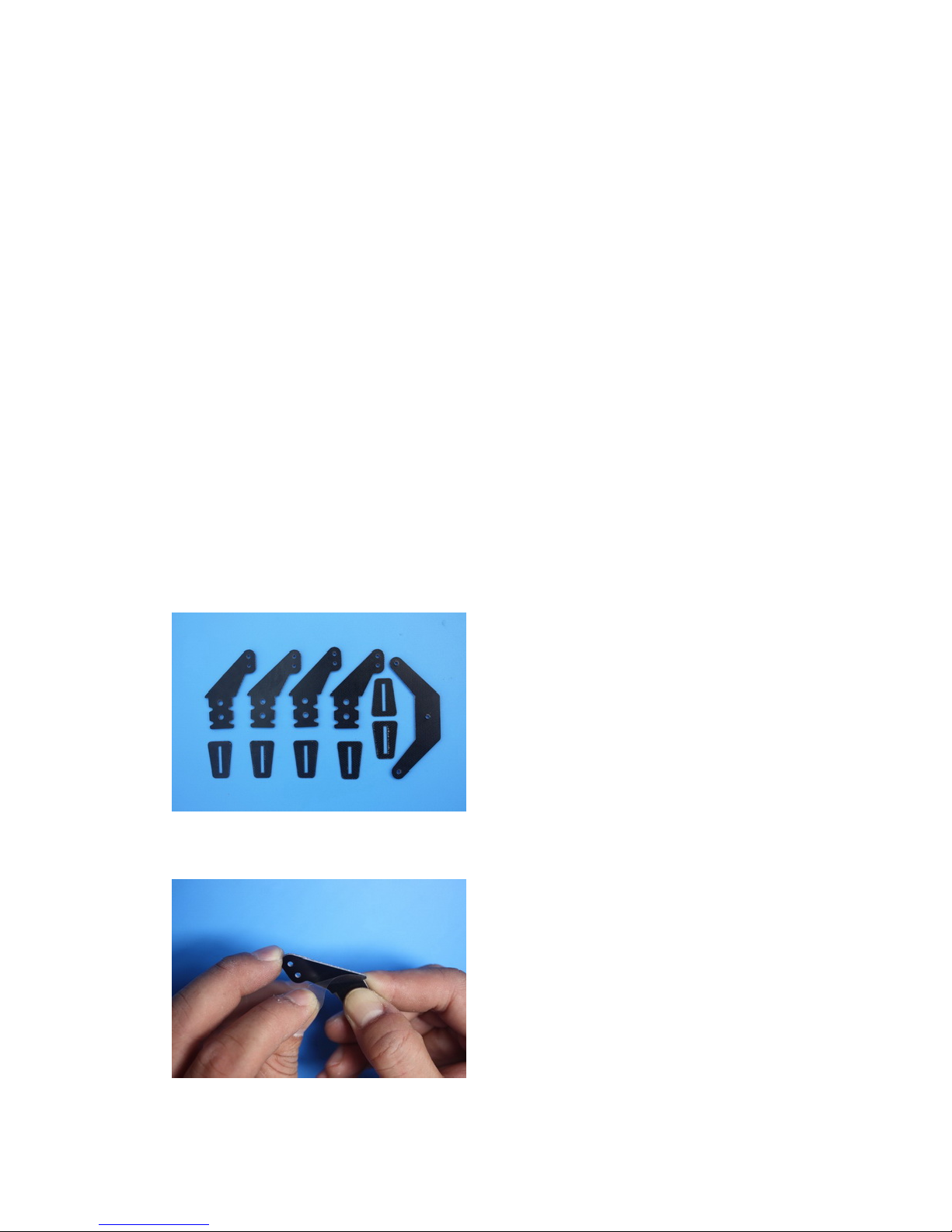
Please verify the accessories before assemble:
• 4 fiber glass servo horns: 2 single horns for ailerons, and 2 for elevators (if you choose to use
single servo to control elevators, you only need to install one control horn and joint the
elevators with a fiber glass bar, please see instruction in “Elevators Assembly” section). 1 dual
horns for rudder.
*There is a layer of protection film on the horns. Please remove the film before installation.
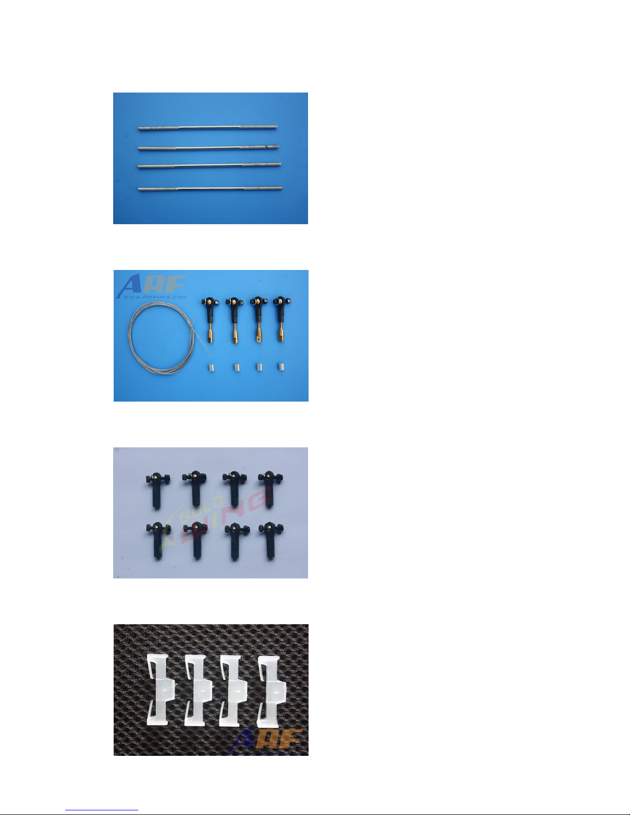
• Pushrods: 4 2x65mm pushrods for aileron & elevator.
Page 11
ARF® MODEL
• Pull-pull hardware set for rudder
• Ball links: 8 for aileron and elevator
• 4 Servo extension safety connector clips
Page 12
ARF® MODEL
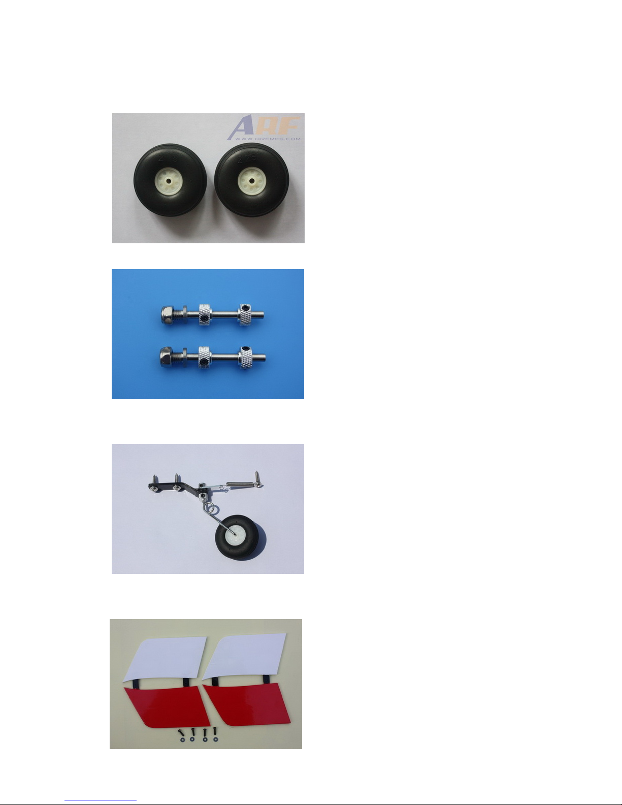
• Main rubber wheels:2 Pcs
• Stainless steel Axle kits: 2 Pcs
• Tail wheel assembly
• Side force generators (mounted with four 3x12mm Hexagon bolts & 2 Washe rs)
Page 13
ARF® MODEL
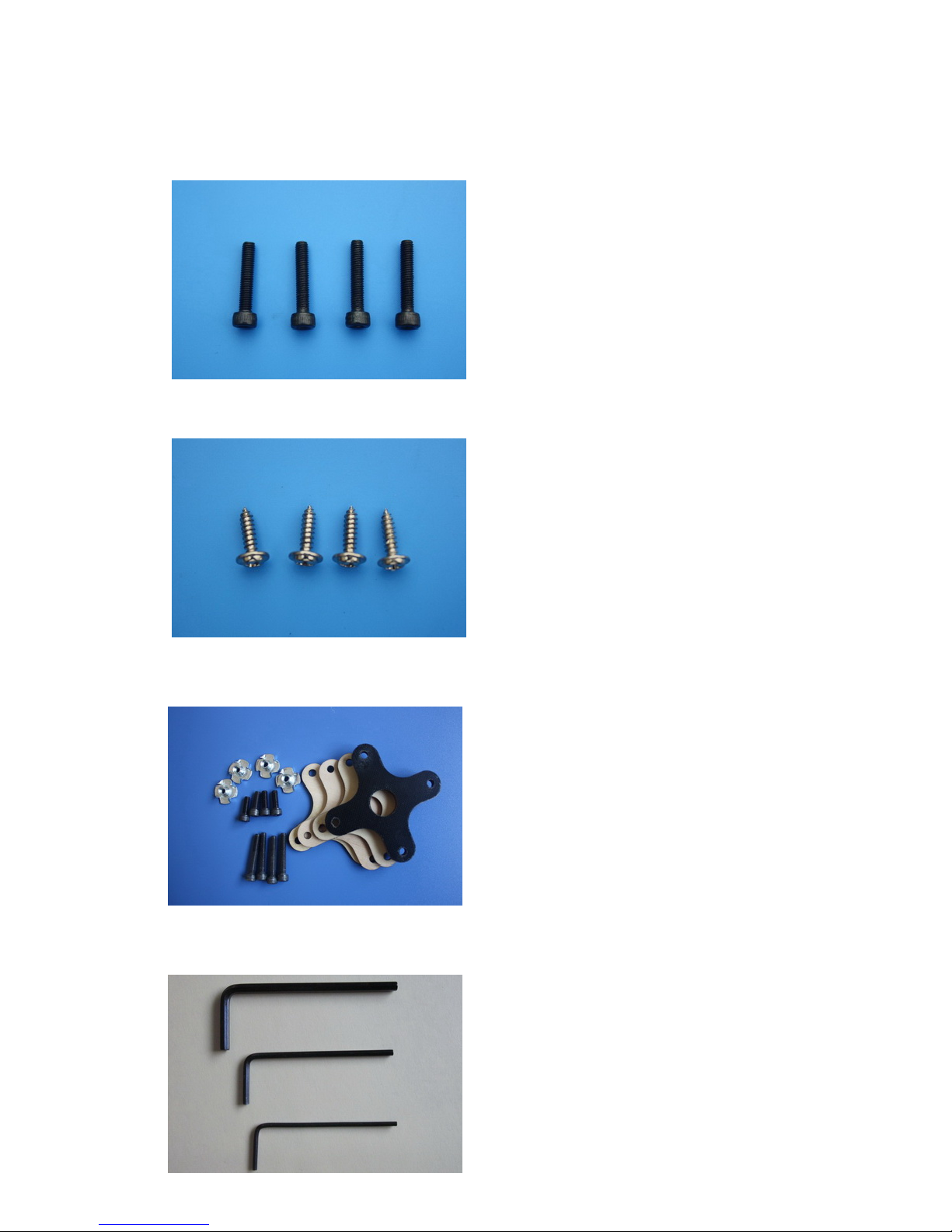
• 4 (3x16mm) hex-head bolts for landing gear mounting
• Screws for cowl: 4(3x12mm) tapping screws
• Motor mounting hardware set
• 3 Hex keys
Page 14
ARF® MODEL
Construction
1. Wing Assembly
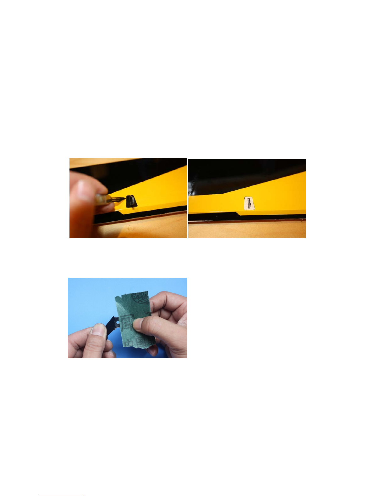
1.1 Locate tw o win g pa nels with ailerons, and two set of con t rol horns and base plates.
1.2 Locate the slot for control horn on aileron, remove the covering over the slot with heated
soldering iron or sharp hobby knife, and m ake sure you do it on the bottom side of the aileron.
Insert control horn into base plate then into the slot, trace the edge of base plate with hobby
knife then remove the underlying covering.
1.3 Use some f ine s andpaper to roughen up the root of c ontrol horn where will be glue d into the
slot.
1.4 Fill the slot and coat the root of control horn and the bottom of base plate with 30 minute epoxy,
insert the horn into the slot, press it down firmly. Wipe off excessive epoxy with alcohol wipes.
Set aside until cured.
Page 15
ARF® MODEL
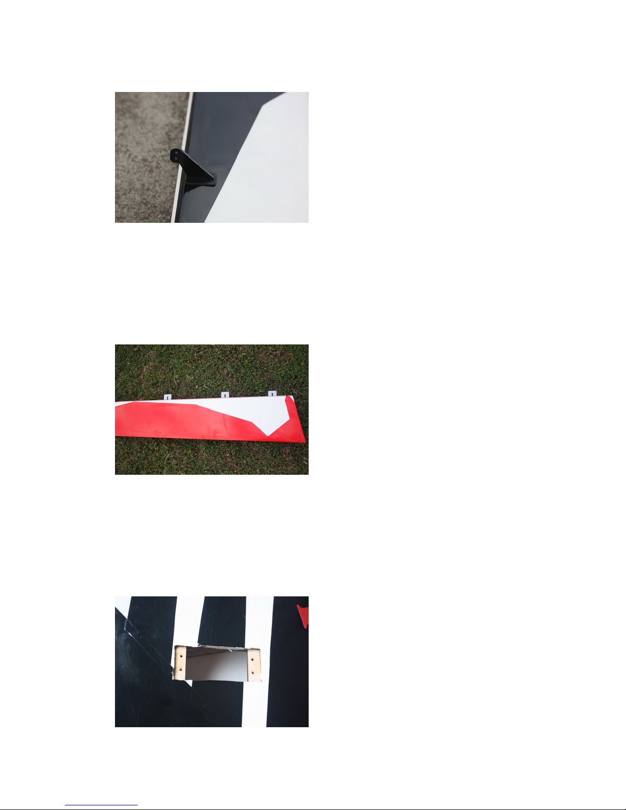
1.5 The slots for CA hinges are pre-cut. Insert CA hinges half wa y i n to t h e hinge slots on aileron,
apply a drop of thin CA to secure the hinges. Then insert all hinges into slots on the wing at
once, align aileron with the wing, move the aileron up and down a few times to reach the
minimal hinge gap while still allowing full deflection of the aileron. When satisfied, apply
more think CA on both top and bottom sides of each hinges.
1.6 Cut the covering from the aileron servo slots from corner to corner and iron down inside the
openings. Connect servo wire exte nsio ns to your servos and secure the connectio n s with the
supplied clips. Feed the servo wires into the wing and out the root. The screw holes for servo
mounting are laser pre-drilled, it is advisable to apply some thin CA to strengthen them, Install
the servos and screw firmly in place.
Page 16
ARF® MODEL
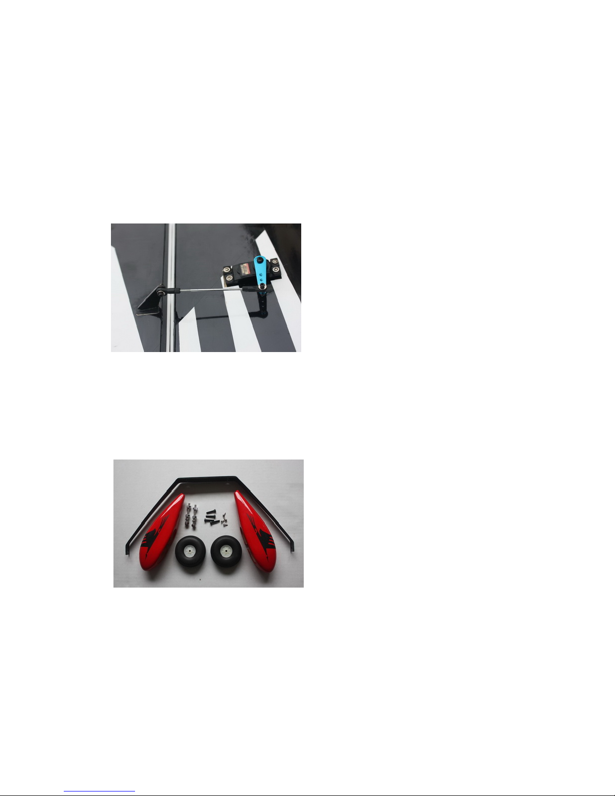
1.7 Use your radio to set the centers of each servo and then assemble and adjust the length of each
control rod. The servo arm should be as close to perpendicular to the control rod as possible
while the aileron is at neutral. Double check all screws, bolts and nuts to assure proper
installation and operation without binding.Once satisfied, permanently att ac h the ball lin ks t o
the servo arms and horns with the supplied screw and nut.
1.8 Check the fina l radio operation of the ailerons and ma ke sur e there is no binding or servo
fighting of each other. Also check to make sur e all lin kage bolts and nuts are secure.
1.9 Repeat this pro cess for the other wing half.
2. Landing Gear Installation
2.1 Locate the landing gear set
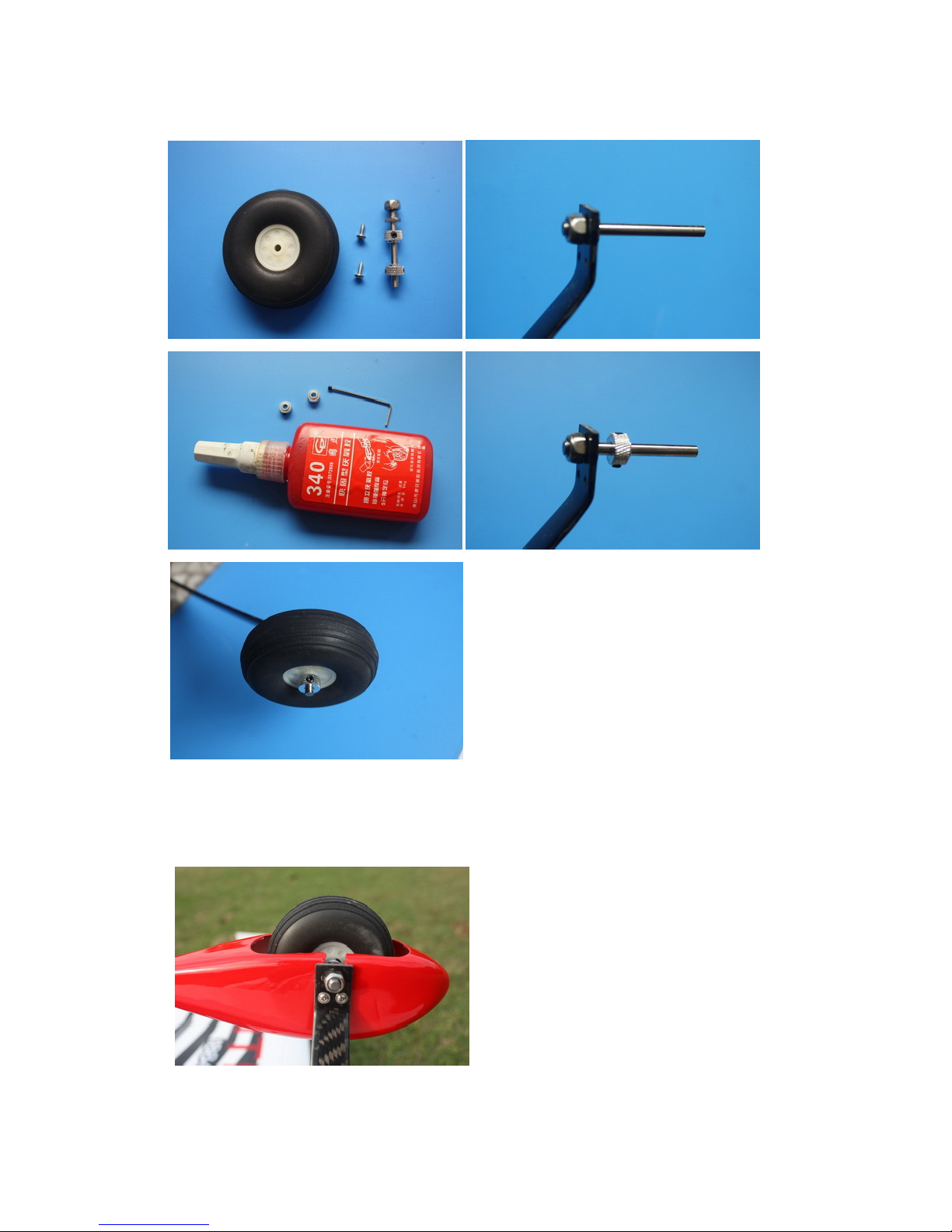
2.2 Install the wheel axles to the landing gear and tighten the nylon-insert lock nut. Install one
wheel collar onto the axle. Use a second wheel collar as a guide to leave a gap on the inboard
of the axle. Use a small drop of thread-lock a n d tighten in place. Slide the wheel onto the axle
and install a second wheel collar also usin g t hre ad-lock on the set screw.
Page 17
ARF® MODEL
2.3 Fit the wheel pant in place and install using the two supplie d screws. Use thread-lock to secure
the screws in place. Repeat the above steps for the other main gear.
Page 18
ARF® MODEL
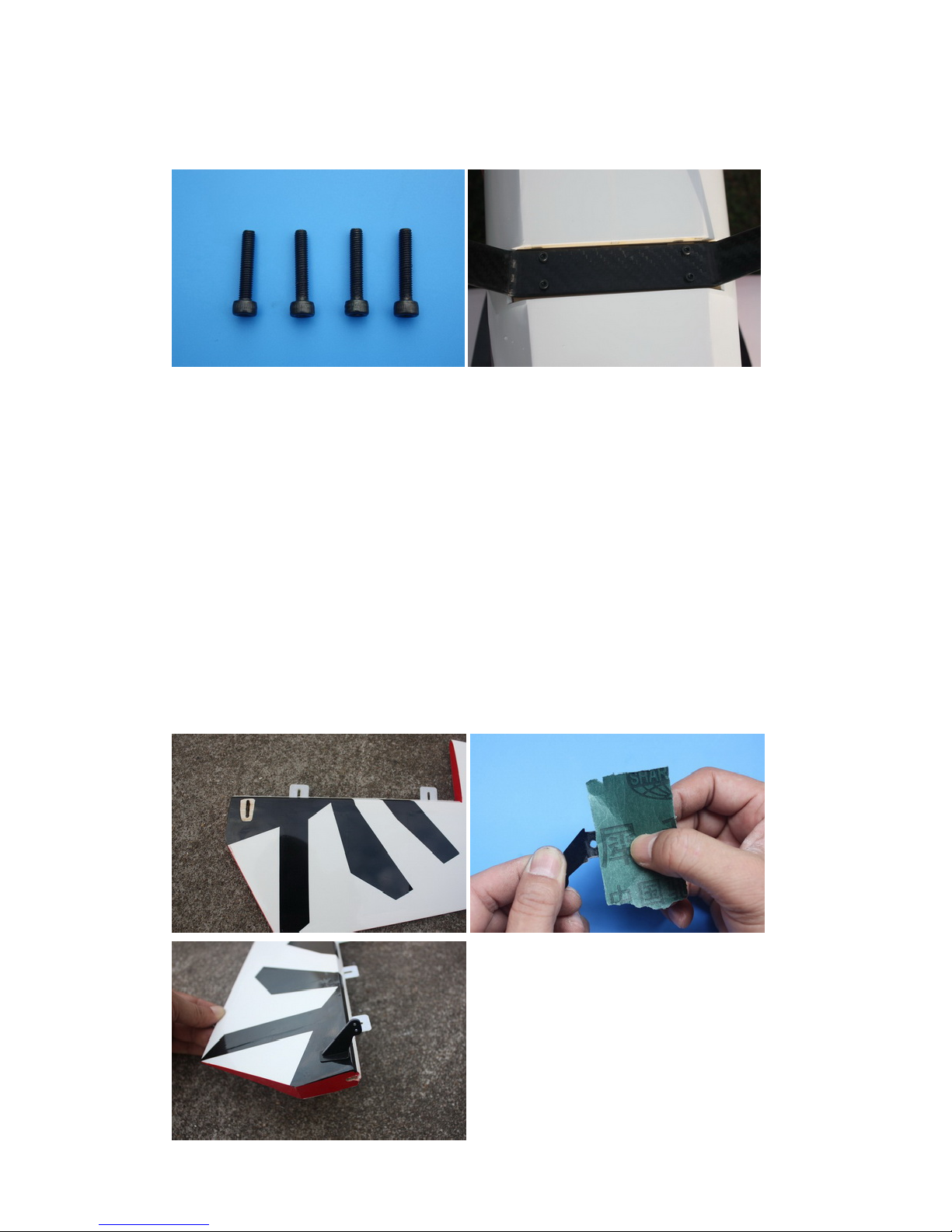
2.4 Bolt the main gear to the bottom of the fuselage using the supplied bolts
3. Elevators Assembly
3.1 Find the control horn slots on bottom side the elevators, use the method described in 1.2-1.4 to
install control horns for elevators. Please note that if you are using dual servos, you need to
install horns on both elevator halves, if you are using signal servo, install horns on one
side only.
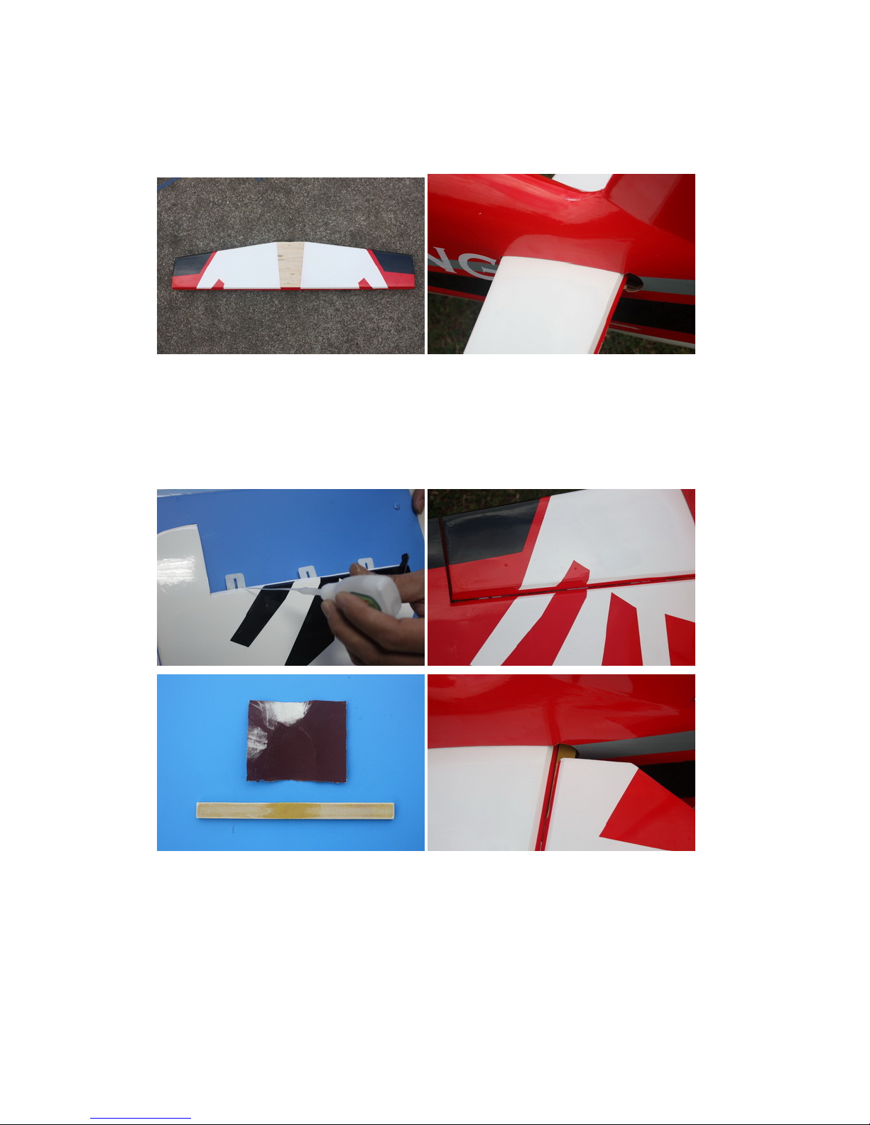
3.2 Remove covering over the hole for horizontal stabilizer on fuselage. Removing covering on the
central part of horizontal stabilizer is recommended for better glue bonding. Insert the
horizontal stabilizer into fuselage, make sure it’s centered. Apply thin and gap-filling medium
CA to glue it in place.
Page 19
ARF® MODEL
3.3 Glue the CA hinge for the ele vator the same way as the main wings
3.4 There is an option to use one servo or two servos for the elevator. If using one servo, the
twohalves of the elevator need to be connected by the included fiberglass bar with glue as
shown below. The picture is for illustr ation o nly. Actually, the connection of the 2 part s needs
to be performed before th e hinges are connected.
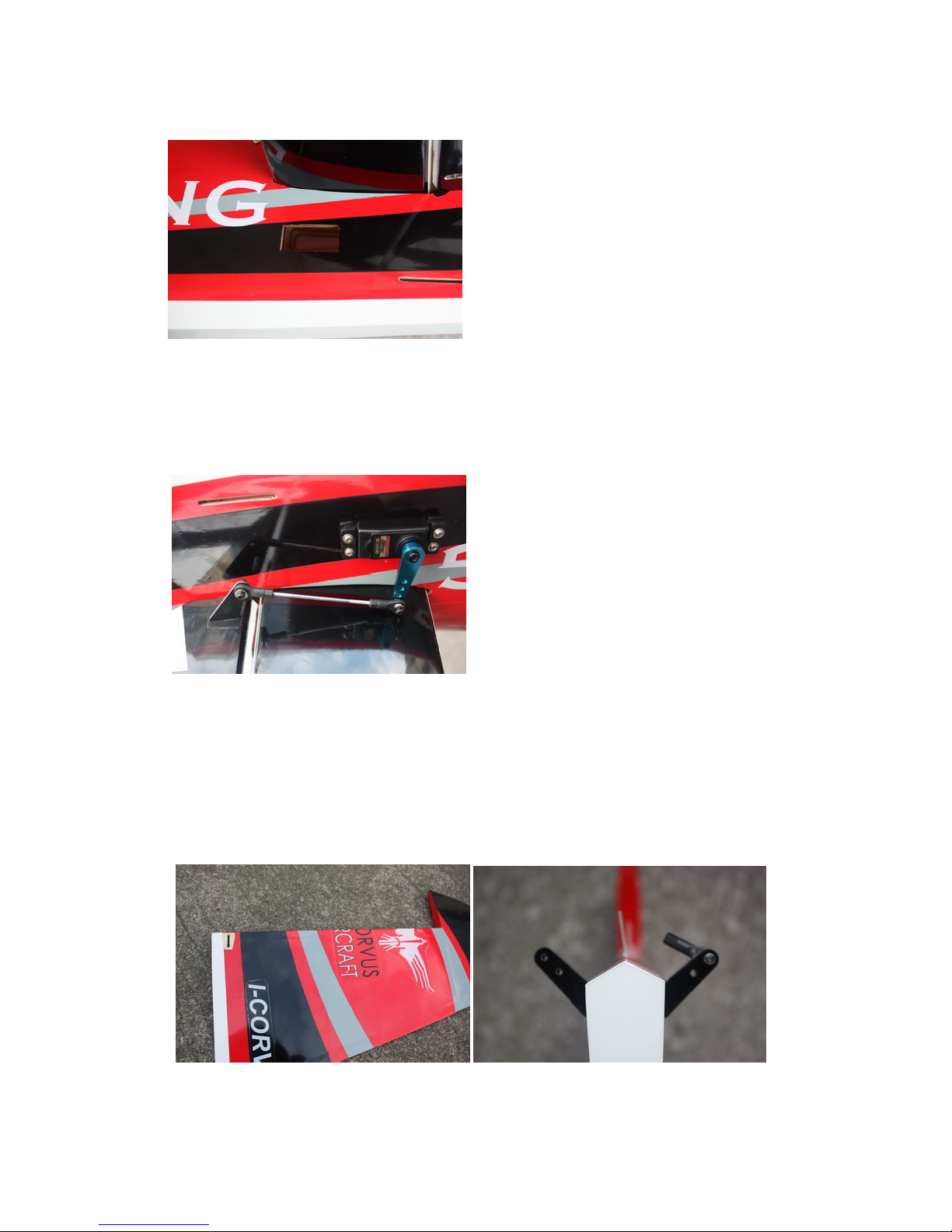
3.5 Locate the s l o ts for elevator servo(s), rem ove covering. Connect wire ex tension to your servos
before feeding the wire into fuselage. Install servo(s) with screws supplied by servo
manufacturer.
Page 20
ARF® MODEL
3.6 Use your radio to set the servo center position and install the large control horn onto the servo.
Assemble the control rod and ball links and adjust the control linkage for proper geometry.
When satisfied, screw the ball link to the servo arm and control horn. The servo arm should be
as close to perpendicular to the control rod as possible while the elevator is at neutral. Double
check all screws, bolts and nuts to assure proper installation and operatio n witho ut bin ding.
4. Rudder Assembly
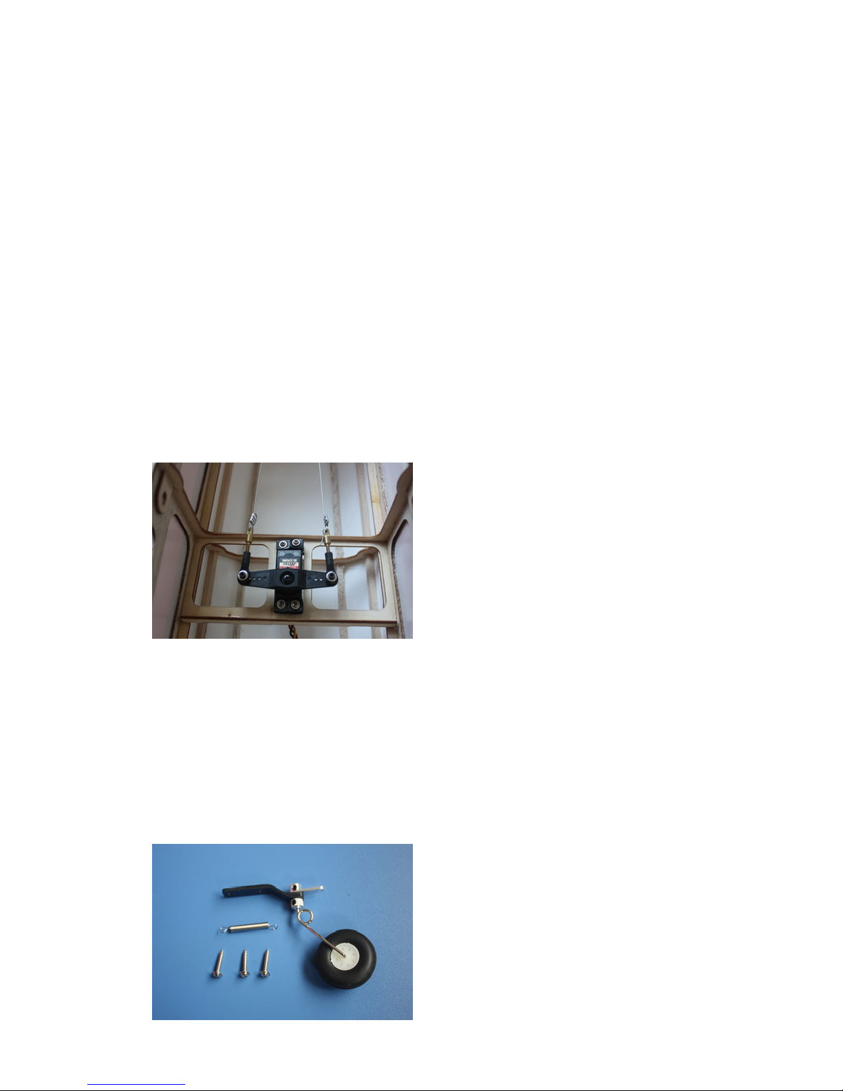
4.1 Locate pull- pull linkage set for rudder.
4.2 Install the d o uble-arm fiberglass contr ol h orns in the same way as you did the elevator and
aileron horns.
4.3 Connect CA hinges for rudder.
Page 21
ARF® MODEL
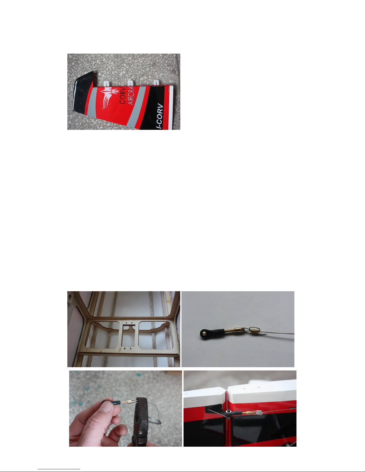
4.4 Locate the pull-pull cable set, threaded couplers, brass swaging tubes, and ball-links. If the
cable is one long piece, cut it into two equal length pieces. Thread one end of the one cable
through a brass tube and then through one of the threaded couplers. Run the cable back
through the brass tube and then loop it back through a second time. Using a set of crimping
pliers, crimps the brass tubetight enough to securely hold the wire in place. Cut off the excess
cable with wire cutters. Wick thin CA into the brass tube to help hold the cable secure.
Repeat for the other cable.
4.5 Thread the couplers about half way into the ball links of the rudder. Hint: remove the ball links
from the rudder horn first to make this step easier and then re-install once the couplers are
threaded on. Feed the loose end of each cable into the cable slots at the rear of the fuselage and
feed them forward towards the servo mount locat i on. A c oat ha nger with a hook on the end can
be useful here if you can’t reach the cable
Page 22
ARF® MODEL
4.6 Use your radio system to center the rudder servo and attach either the supplied arm or an
appropriate arm for your servo. T hread one of the ball links about half way onto one of the
threaded couplers. Feed the loose en d of one of the cables through a brass tube and then
through the threaded coupler. Holding the rudder centered, adjust the cable length as tight as
possible while checking the ball li nk position over the servo arm. When satisfied with the
position, pinch the cable aro un d the threaded coupler and then feed the lo ose end back through
the brass tube. Loop the cable back thro ug h the brass tube as before and crimp the brass tube
three times just tight enough not to cut the brass tube but enough to securely hold the wire in
place. Cut off the excess cable with wire cutters. Wick thin CA into the brass tube to help hold
the cable secure. Repeat for the other cable. Hint: Once you have established the position of
the threaded coupler on the cable, you can remove the ball link from the rudder horn to give
you more working slack in the fuselage. Re-ins ta ll the ball link prior to setting the other cable.
4.7 Check the o peration of the rudder using your radio and make sure there is no binding and the
cables are adjusted properly. You may have to tighten the cables after a few flights as they
may stretch slightly from the initial installation.
5. Tail Wheel Installation
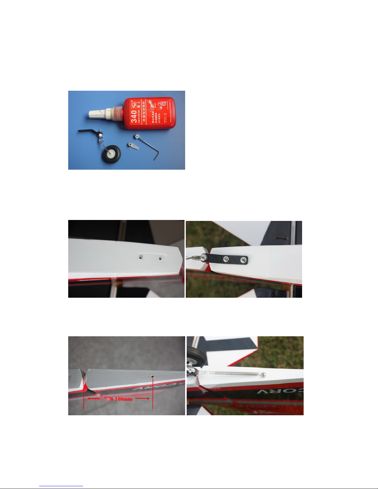
5.1 Tail wheel assembly for electric airplanes.
Page 23
ARF® MODEL
5.2 Tail wheel kit is pre-assembled in factory, for safety, please remove all screws and then re-
assemble with thread locker.
5.3 Drill 2 mm holes on the bottom rear of the fuselage, secure the tailwheel bracket with the
provided screws. For best results, the pi v ot p oin t o f the assembly should be over the hinge line
of the rudder.
5.4 Drill a hole on the bottom of rudder, 70-100mm away for the hinge line. Secure the tail wheel
spring with provided self-threading scr ew.
6. Motor Mounting
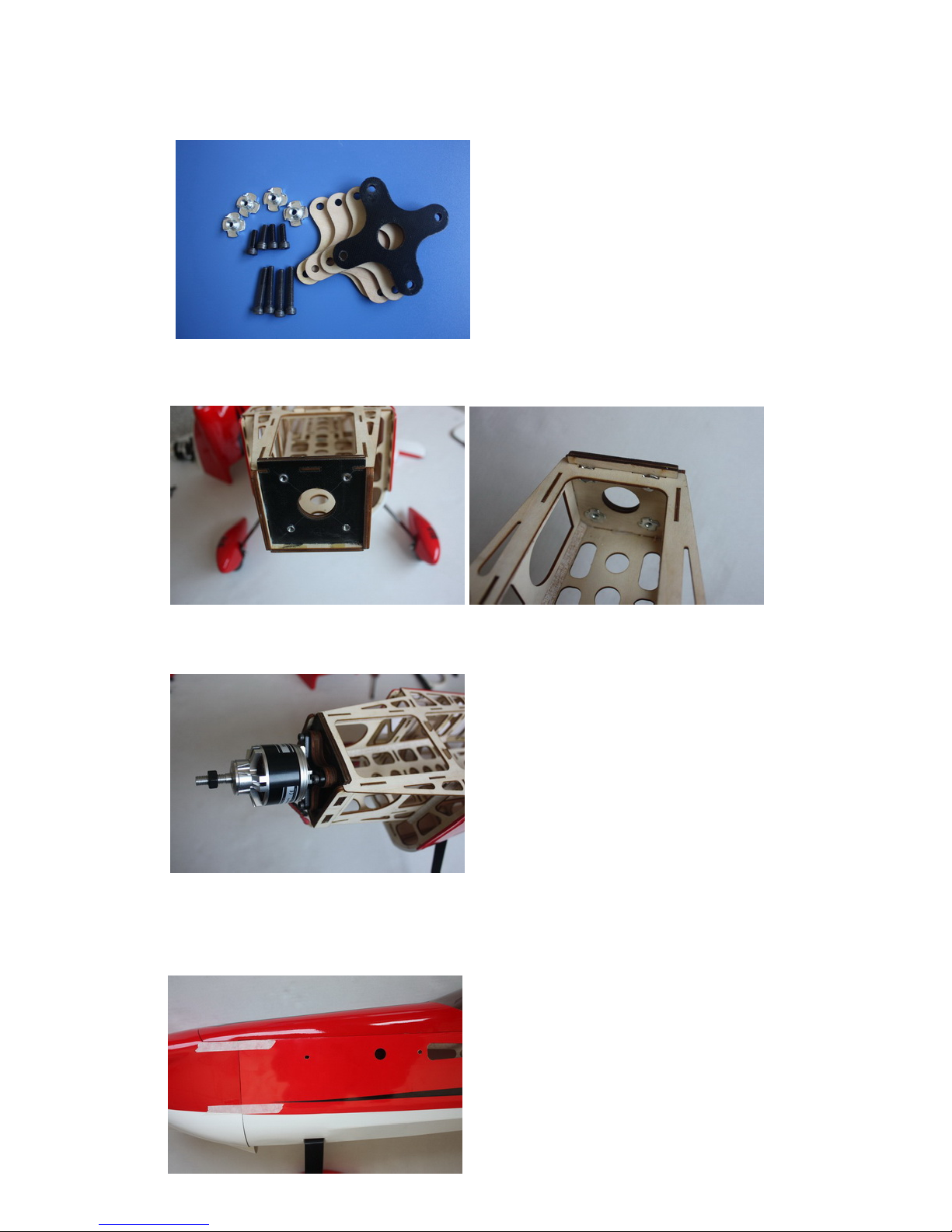
6.1 Find the ha rdware set for motor inst allation in the hardwa re package.
Page 24
ARF® MODEL
6.2 Drill holes on f i rewall with 5 mm drill bit, install blind n uts be hind the firewall.
6.3 Since the position of cowl is fixed and length of motors vary, you may need to use provided
washers and wood crosses to position you motor properly.
7. Cowl Installation
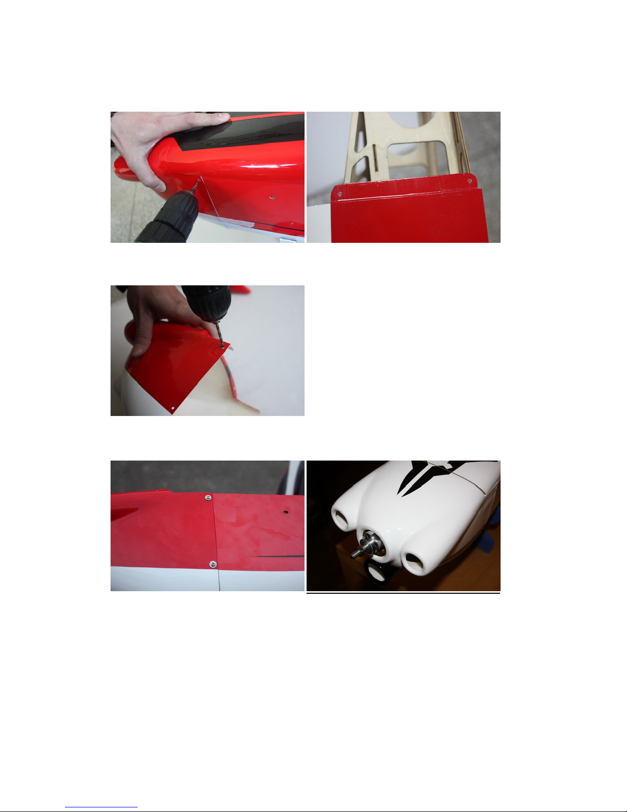
7.1 Test fit the cowl first, make sure it fits well with canopy and fuselage.
Page 25
ARF® MODEL
7.2 Drill 2mm holes on cowl and fuselage .
7.3 Enlarge the holes on cowl with 3mm drill bit.
7.4 Secure the cowl with 3X12mm self-threading screws.
8. Final Radio System Installlation
8.1 Whether you 72 MHz systems or the newer 2.4 GHz systems, proper radio installation and care
is vital to the safe and reliable operation of your aircraft. Follow the manufacturer’s instruction
for installation guidance of receivers an d ba tte ries paying attention to factors such as vibration
isolation, adequate cooling, and clearances.
8.2 Mount your re ciever(s) securely in a location which provides a clean and maintenance free
solution to your setup. All servo wires should be neatly routed and secured in place so they
will not come loose or flop around during flight.
Page 26

ARF® MODEL
8.3 The fuselag e ply sides provide space to mount your switc he s just below the canopy. Mount
your switches according to the manufacturer’s instructions and route your wires safely and
securely as above.
8.4 Your receiver battery(s) can be mounted in a variety of locations depending on your balance
needs. Regardless of where you mount your batteries it is vital that they are very secure with
no possibility of coming loose. Use d o uble sided velcro to hold the batteries from sliding
around and then use zip ties or velcr o str aps to secure them tightly in place.
8.5 Servo and battery leads are the life blood of your aircraft. Make sure all wires ar e to p q uality
and connectors are tight and display no loose pins or frayed wires. Servo clips are provided in the
kit for your convenience. These servo clips can even be glued to the wood structure using CA if
desired.
8.6 Check all radio programming and control surface operations thouroughly before your initial
flight. Check your radio range according to the radio manufacturer’s instructions both with the
engine off and running.
9. Balancing and Pre-Flight
Most state of the art aerobatic aircraft allow for a wide margin for balancing dependi ng on w hat
level of precision or freestyle the pilot prefers. To perform properly without being too pitch
sensitive, you must not go too aft on the CG. We recommends an initial CG setting of 92-
109mm(3.6-4.3inches) behind the leading edge of the wing at the root. More experienced pilots
may want to set the CG further aft for more 3D capability. Varying weights of motor and radio
gear will dictate how you should install each.
Note: The best way to check your balance is to trim for level flight at about 1/2 to 3/4 throttle and
then roll inverted. The aircraft should maintain level flight with very little to no down elevator
input. If the aircraft climbs when inverted then you’ve probably got your CG too far aft. If th e
nose drops more than slightly, t he n you are most likely nose heavy.
Recommended control surface deflections:
Low Rate High Rate
Elevator 15 degrees 45-50 degrees
Rudder 25 degrees 40-45 degrees
Ailerons 25 degrees 35-40 degrees
10.Final Assembly and Pre-Flight Inspections
Page 27
ARF® MODEL
10.1 Before arriving at your flying field, be sure all your batteries are properly charged and all
radio systems are in prope r working order.
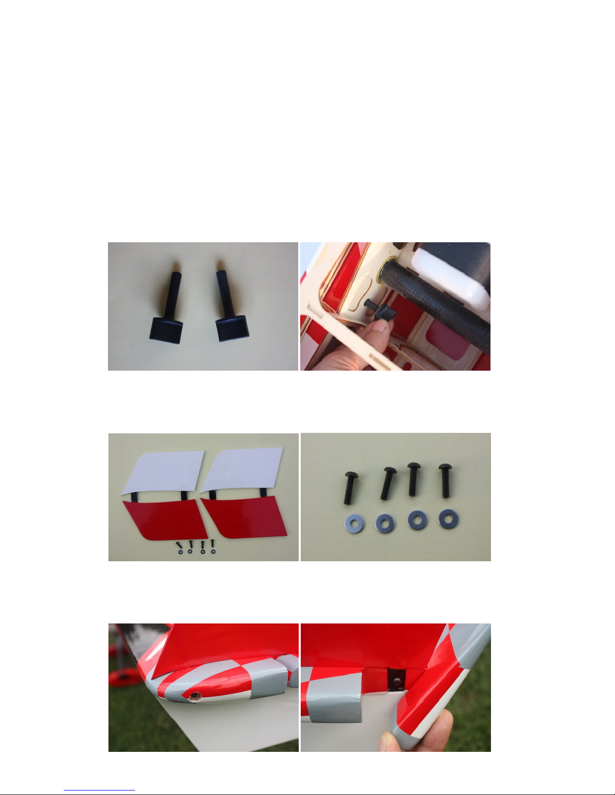
10.2 Install the wings onto the fuselage being careful to align the wing tube with the wings and not
force it. The wing tube may be initially tight but will loosen some with use. Guide yo ur s er vo
wires into the fuselage openings and connect to the proper aileron channels. Servo clips are
recommended. Once you have the w in g s fully seated in the fuselage tighten t he wing bolts inside
the fuselage.
10.3 Side force generators Assembly, cut the wing film needed to be instal the SFG. Fixed the SFG
Use M3X12 Hexagon socket screw and washers.
10.4 If you have removed your horizontal stabilizers, install them once again and check all bolts
and connections.
Page 28
ARF® MODEL
10.5 Check all control surfaces fo r secure hinges by performed a slight tug on the control surfaces
and observing if there is an y give in the hinges. Check all control rods, ball links, servo screws, etc.
for proper operation and installation.
10.6 Check your batteries and perform a proper range check once again with the engine off and
running. Be sure all surfaces are moving in the correct direction and the proper amount for your
flying setup.
Accessories
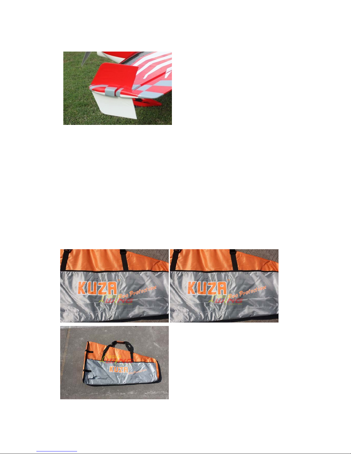
*Wingbags for 70E ORANGE/SILVER (Not included)
Page 29
ARF® MODEL
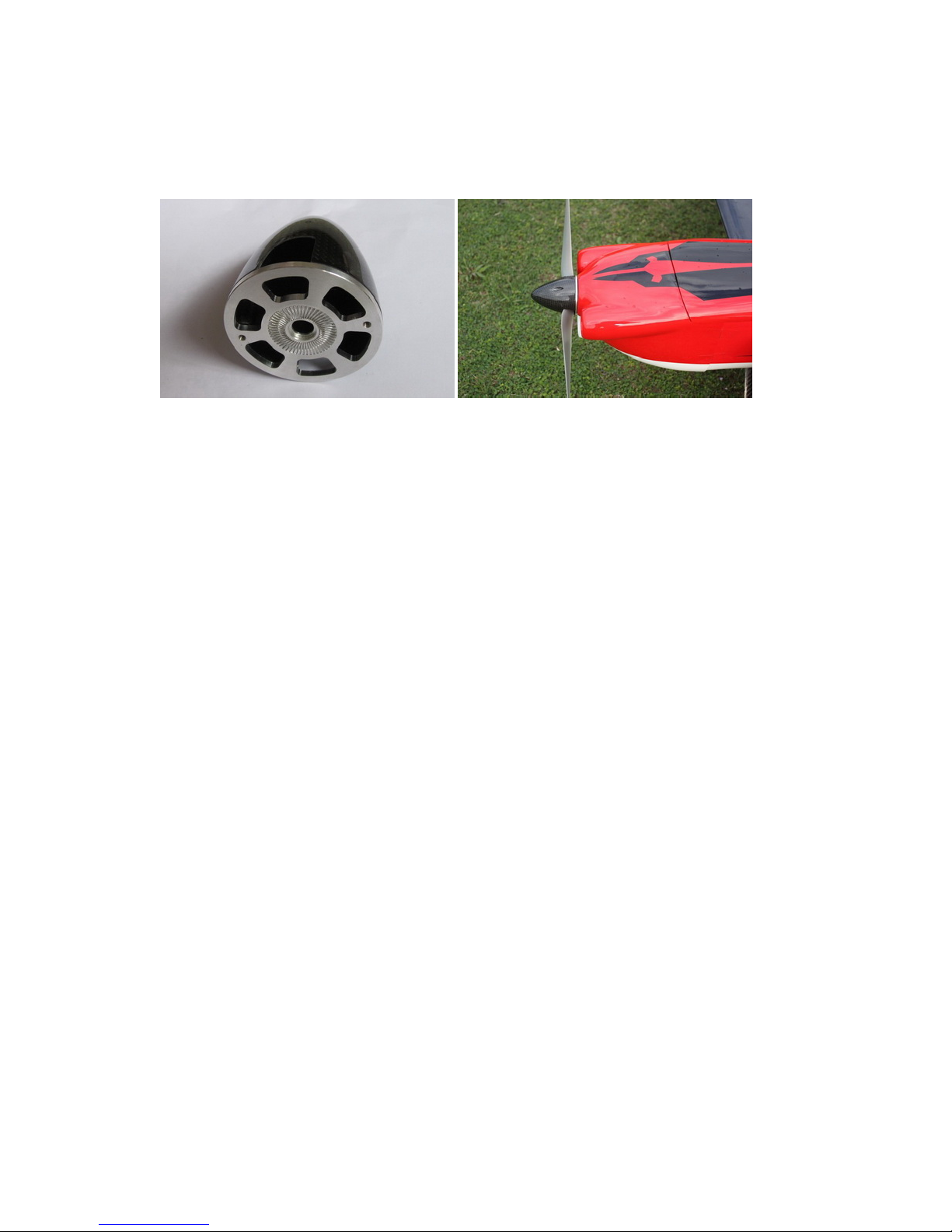
*2 -1/4in CF spinner (Not Included)
 Loading...