

Page 1

General Motors.
The Collision Repair
Industry Leader.
This booklet provides you with detailed repair information.
It is important to note that serviceability has been an integral part of the development of these
vehicles. General Motors has made every effort to take the technician’s concerns into
consideration and to make sure we are providing quality information for quality technical
repairs.
General Motors recognizes the important role that each of you plays in keeping customers
happy and satisfied with our vehicles. That is why we have dedicated all our service resources
to giving you the knowledge, information and tools you need to accurately and efficiently
service these vehicles. We feel confident that working together with you, we have what it takes
to achieve total customer satisfaction.
Service information is also available on the web.
• This website includes service repair information for the total vehicle and is a
subscription based site. (www.acdelcotechconnect.com)
• This website includes select collision repair information only and is downloadable
and free to the user. (www.techinfo.gmgoodwrench.com)
Page 2

TABLE OF CONTENTS
General Information ....................................... 1-1
Actions to Take When Working with
Fuel Caution
Approved Equipment for Collision
Repair Caution
Battery Disconnect Caution
Collision Sectioning Caution
Foam Sound Deadeners Caution
Glass and Sheet Metal Handling Caution
Safety Glasses Caution
SIR Caution
Sound Deadener Foam in the Lock Striker Pillars
Caution
Fastener Notice
............................................... 1-1
............................................ 1-1
............................. 1-1
............................ 1-1
.................... 1-1
........ 1-1
................................... 1-1
.................................................... 1-1
....................................................... 1-1
.............................................. 1-1
2006 Chevrolet Corvette Z06 ........................ 2-1
Structure Identification
Dimensions - Body (Motor Compartment -
Corvette)
Dimensions - Body (Z06)
Impact Bar Replacement - Front
Bumper (Z06)
Hood Plate Stud Replacement (Z06)
Wheelhouse Replacement - Front (Z06)
Pillar Lock Front Door Replacement -
Outer (Z06)
Impact Bar Replacement - Rear
Bumper (Z06)
Rail Replacement - Front (Z06)
Rail Replacement - Front Section (Z06)
Rail End Replacement - Front (Z06)
Rail End Replacement - Rear (Z06)
Sleeved Butt Joint Repair (Z06)
Windshield Frame Replacement
Door Opening Frame Replacement - Side
..................................................... 2-3
............................................... 2-11
..................................... 2-1
................................ 2-4
............................................. 2-5
............... 2-7
........ 2-10
............................................ 2-14
..................... 2-20
........ 2-22
.............. 2-30
.............. 2-34
.................... 2-36
.................... 2-38
...... 2-41
Rail Replacement - Rear (Z06)
Rail Replacement - Rear Section (Z06)
Floor Panel Replacement (Z06)
Compartment Panel Replacement -
Rear (Corvette)
Compartment Panel Frame Replacement -
Rear (Corvette)
Sheet Molded Compound (SMC) Panel
Bonding
.................................................... 2-62
......................................... 2-56
......................................... 2-59
..................... 2-43
..................... 2-53
2006 Pontiac Solstice/
2007 Saturn SKY
Dimensions - Body (Door Openings)
Dimensions - Body (Motor Compartment)
Hinge Pillar Body Reinforcement
Replacement - Front
Hinge Pillar Body Replacement - Front
Windshield Frame Header Panel
Replacement - Front
Pillar Lock Front Door Replacement -
Outer
Pillar Lock Front Door Replacement -
Inner
Quarter Panel Replacement - Outer
Impact Bar Replacement - Rear Bumper
Rail Replacement - Front Section
Sleeved Butt Joint Repair
Windshield Panel Replacement - Lower
Door Opening Frame Replacement - Side
Rail Replacement - Rear Section
Floor Panel Replacement
Compartment Panel Replacement - Rear
Panel Replacement - Rear End
Sheet Molded Compound (SMC) Panel
Bonding
........................................................ 3-10
........................................................ 3-12
.................................................... 3-43
........................... 3-1
.................................... 3-3
.................................... 3-7
............... 3-15
.................. 3-21
.............................. 3-25
.................. 3-31
.............................. 3-35
..................... 3-40
......... 2-46
General Information2006 Chevrolet Corvette Z062006 Pontiac Solstice/2007 Saturn SKY
............... 3-1
........ 3-2
............ 3-5
....... 3-18
......... 3-26
...... 3-29
....... 3-38
1
Page 3

General Information
Actions to Take When Working with Fuel
Caution
Caution: Fuel Vapors can collect while servicing
fuel system parts in enclosed areas such as a
trunk. To reduce the risk of fire and increased
exposure to vapors:
• Use forced air ventilation such as a fan set
outside of the trunk.
• Plug or cap any fuel system openings in order
to reduce fuel vapor formation.
• Clean up any spilled fuel immediately.
• Avoid sparks and any source of ignition.
• Use signs to alert others in the work area that
fuel system work is in process.
Approved Equipment for Collision Repair
Caution
Caution: To avoid personal injury when exposed
to welding flashes or to galvanized (Zinc Oxide)
metal toxic fumes while grinding/cutting on
any type of metal or sheet molded compound, you
must work in a properly ventilated area, wearing
an approved respirator, eye protection, earplugs,
welding gloves, and protective clothing.
Foam Sound Deadeners Caution
Caution: Foam sound deadeners must be removed
from areas within 152.4 mm (6 in) of where flame
is to be used for body repairs. When reinstalling
foam sound deadeners, avoid inhaling fumes
as bodily injury may result.
Glass and Sheet Metal Handling Caution
Caution: When working with any type of glass
or sheet metal with exposed or rough edges, wear
approved safety glasses and gloves in order to
reduce the chance of personal injury.
Safety Glasses Caution
Caution: Wear safety glasses in order to avoid eye
damage.
SIR Caution
Caution: When performing service on or near the
SIR components or the SIR wiring, the SIR
system must be disabled. Refer to SIR Disabling
and Enabling Zones. Failure to observe the correct
procedure could cause deployment of the SIR
components, personal injury, or unnecessary SIR
system repairs.
General Information
Battery Disconnect Caution
Caution: Before servicing any electrical
component, the ignition key must be in the OFF or
LOCK position and all electrical loads must be
OFF, unless instructed otherwise in these
procedures. If a tool or equipment could easily
come in contact with a live exposed electrical
terminal, also disconnect the negative battery
cable. Failure to follow these precautions
may cause personal injury and/or damage to the
vehicle or its components.
Collision Sectioning Caution
Caution: Sectioning should be performed only in
the recommended areas. Failure to do so may
compromise the structural integrity of the vehicle
and cause personal injury if the vehicle is in a
collision.
Sound Deadener Foam in the Lock Striker
Pillars Caution
Caution: Sound deadener foam in the lock striker
pillars can be a fire hazard. Create a weld flange
to avoid welding directly to the lock striker pillars
as damage to the vehicle and serious bodily
injury may result.
Fastener Notice
Notice: Use the correct fastener in the correct
location. Replacement fasteners must be the correct
part number for that application. Fasteners requiring
replacement or fasteners requiring the use of
thread locking compound or sealant are identified in
the service procedure. Do not use paints, lubricants, or
corrosion inhibitors on fasteners or fastener joint
surfaces unless specified. These coatings affect
fastener torque and joint clamping force and may
damage the fastener. Use the correct tightening
sequence and specifications when installing fasteners
in order to avoid damage to parts and systems.
General Information 1-1
Page 4
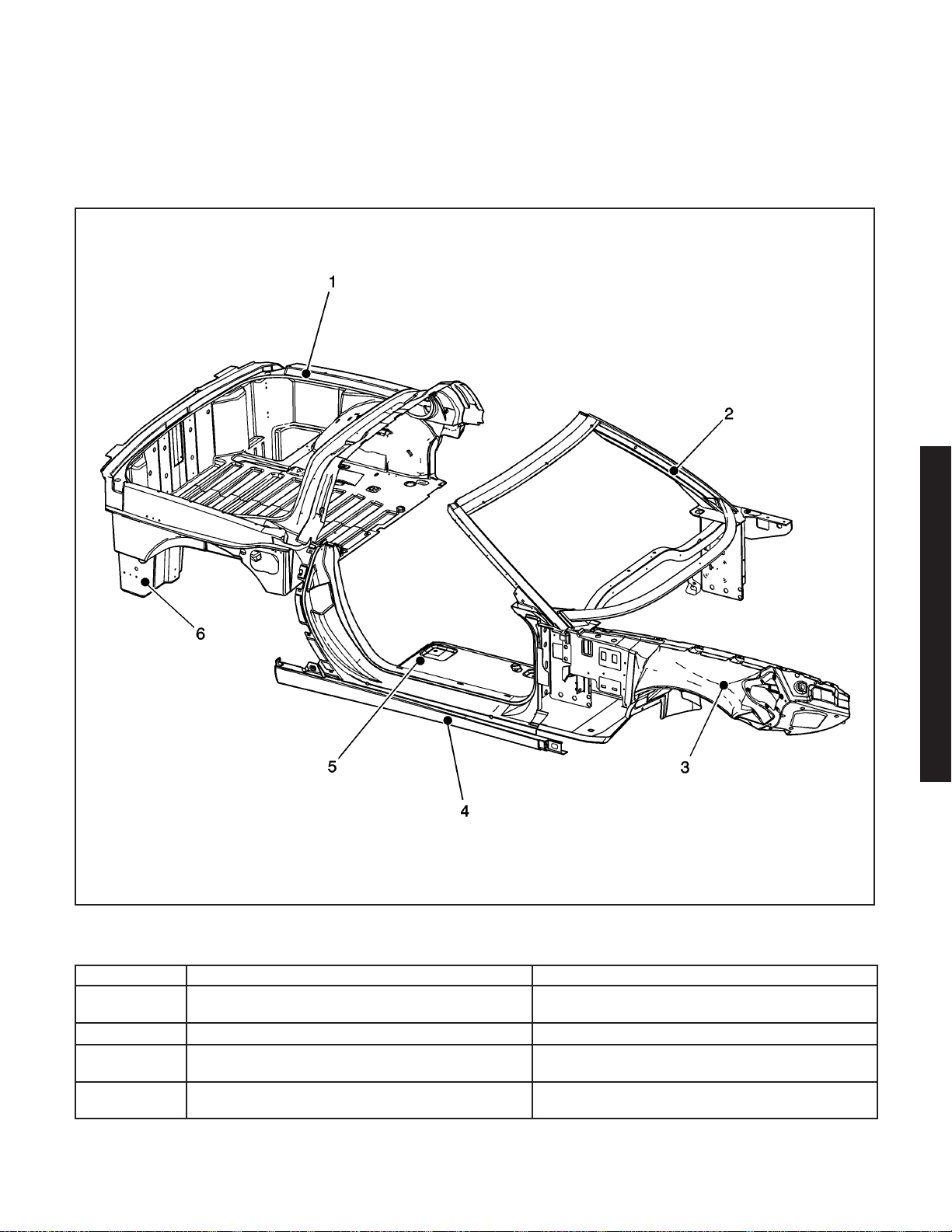
2006 Chevrolet Corvette Z06
Visual Identification
Structure Identification
Inner Panel Identification
Structure Identification
Number Description Procedure
1 Rear Compartment Panel Frame
2 Windshield Frame Windshield Frame Replacement on page 2-38
3 Front Wheelhouse
4 Side Door Frame Opening
Compartment Panel Frame Replacement - Rear
(Corvette) on page 2-59
Wheelhouse Replacement - Front (Z06)
on page 2-10
Door Opening Frame Replacement - Side
on page 2-41
2006 Chevrolet Corvette Z06 2-1
2006 Chevrolet Corvette Z06
1659020
Page 5
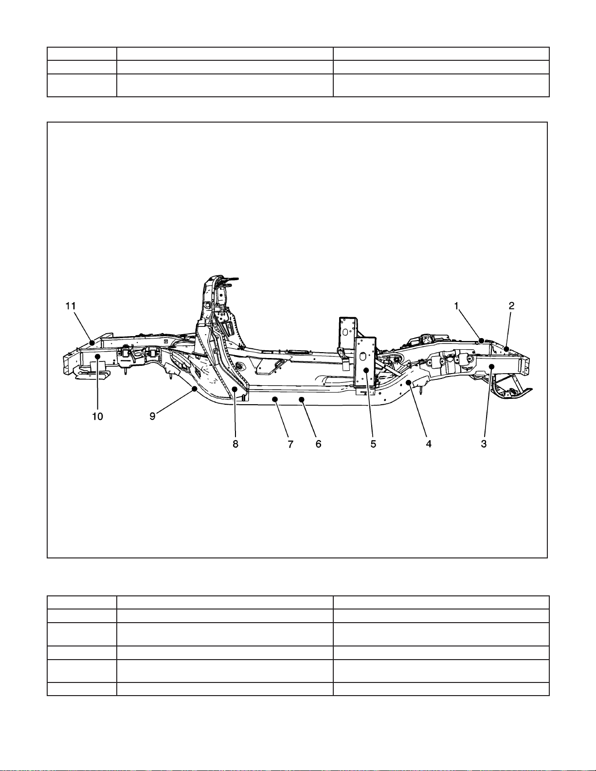
Structure Identification (cont’d)
Number Description Procedure
5 Floor Panel Floor Panel Replacement (Z06) on page 2-53
6 Rear Compartment Panel
Frame Identification
Compartment Panel Replacement - Rear (Corvette)
on page 2-56
Structure Identification
Number Description Procedure
1 Hood Plate Stud Hood Plate Stud Replacement (Z06) on page 2-7
2 Front Bumper Impact Bar
3 Front Rail End Rail End Replacement - Front (Z06) on page 2-30
4 Front Rail Section
5 Front Body Hinge Pillar Hinge Pillar Body Replacement - Front
Impact Bar Replacement - Front Bumper (Z06)
Rail Replacement - Front Section (Z06)
2-2 2006 Chevrolet Corvette Z06
1658114
on page 2-5
on page 2-22
Page 6
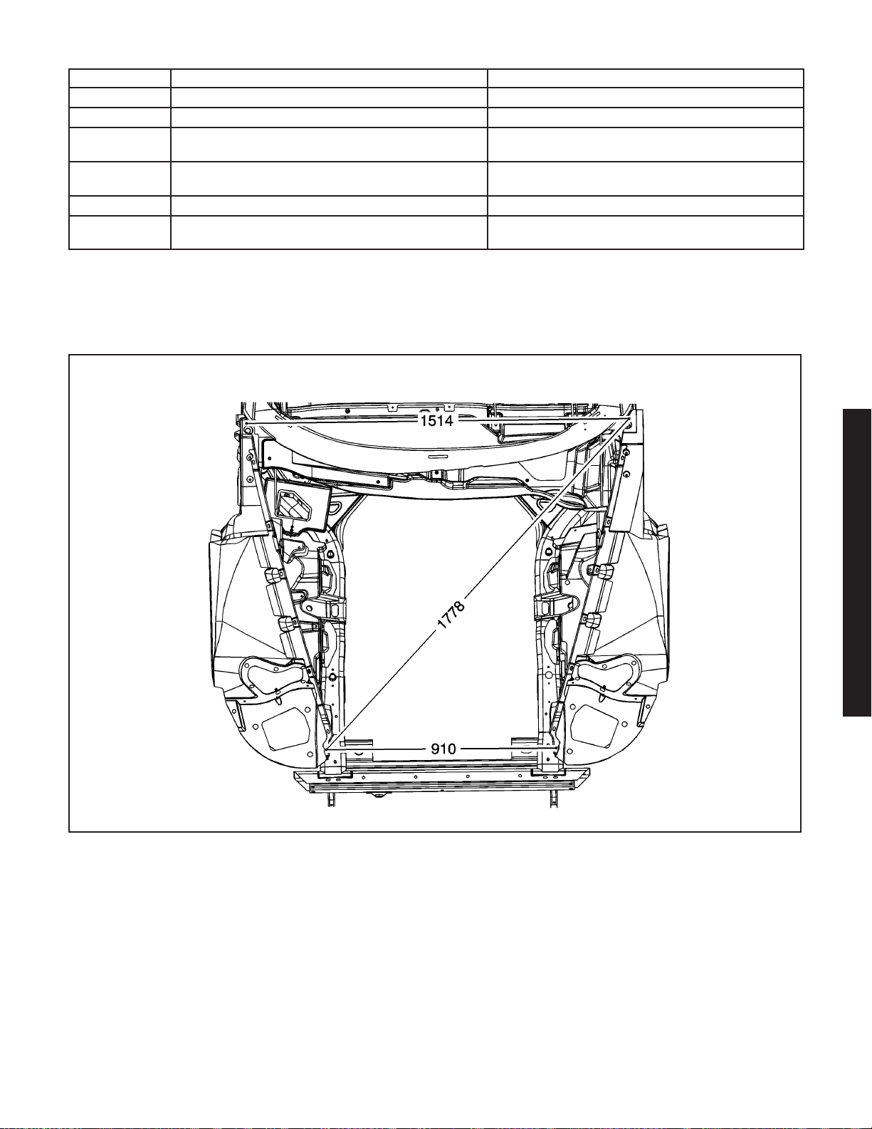
Structure Identification (cont’d)
Number Description Procedure
6 Front Rail Rail Replacement - Front (Z06) on page 2-20
7 Rear Rail Rail Replacement - Rear (Z06) on page 2-43
8 Front Door Lock Pillar
9 Rear Rail Section
10 Rear Rail End Rail End Replacement - Rear (Z06) on page 2-34
11 Rear Bumper Impact Bar
Pillar Lock Front Door Replacement - Outer (Z06)
Rail Replacement - Rear Section (Z06)
Impact Bar Replacement - Rear Bumper (Z06)
Specifications
Dimensions - Body (Motor Compartment - Corvette)
on page 2-11
on page 2-46
on page 2-14
1499874
2006 Chevrolet Corvette Z06 2-3
2006 Chevrolet Corvette Z06
Page 7
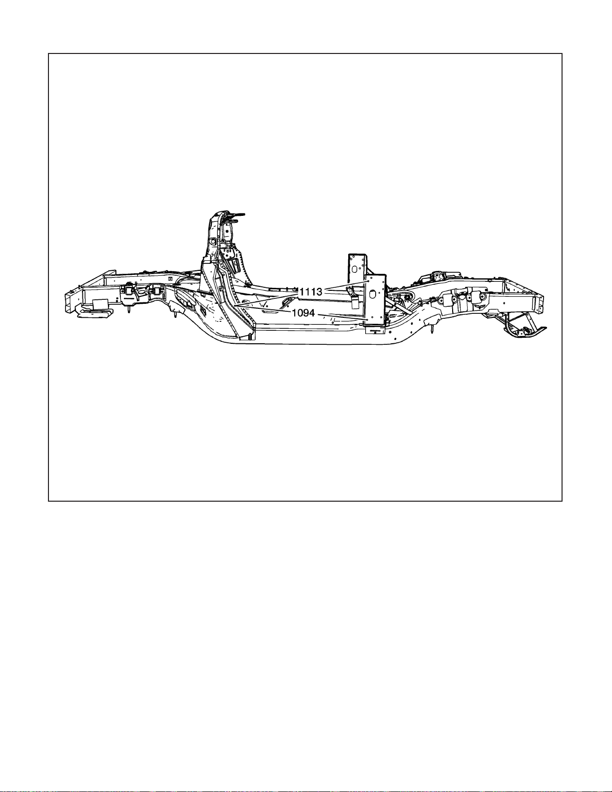
Dimensions - Body (Z06)
2-4 2006 Chevrolet Corvette Z06
1658107
Page 8
Repair Instructions
Impact Bar Replacement - Front
Bumper (Z06)
Tools Required
J 42058 Frame Adapter Clamp
Removal Procedure
Caution: Refer to Approved Equipment for
Collision Repair Caution on page 1-1.
1. Disable the SIR system. Refer to SIR Disabling
and Enabling Zones.
2. Disconnect the negative battery cable. Refer to
Battery Negative Cable Disconnect/Connect
Procedure (7.0L) or Battery Negative Cable
Disconnect/Connect Procedure (6.0L).
3. Remove all related panels and components.
4. Repair as much of the damage as possible to the
factory specifications.
5. Use J 42058 to secure the vehicle if pulling and
straightening is required.
6. Note the location and remove the sealers and
anti-corrosion materials from the repair area.
Refer to Anti-Corrosion Treatment and Repair.
Important:
• Hand tools, saw blades and abrasives used for
aluminum repairs should be dedicated for
aluminum only to prevent contamination.
• When removing welds, favor the bumper bar side
of the weld joint.
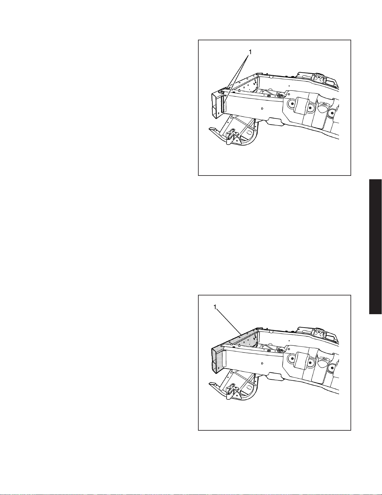
7. Locate and remove all factory welds (1) attaching
the front bumper bar to the front frame rails. Note
the location of the welds for installation of the
new bumper bar.
8. Remove the damaged bumper bar (1).
1656614
2006 Chevrolet Corvette Z06
1656635
2006 Chevrolet Corvette Z06 2-5
Page 9
181153
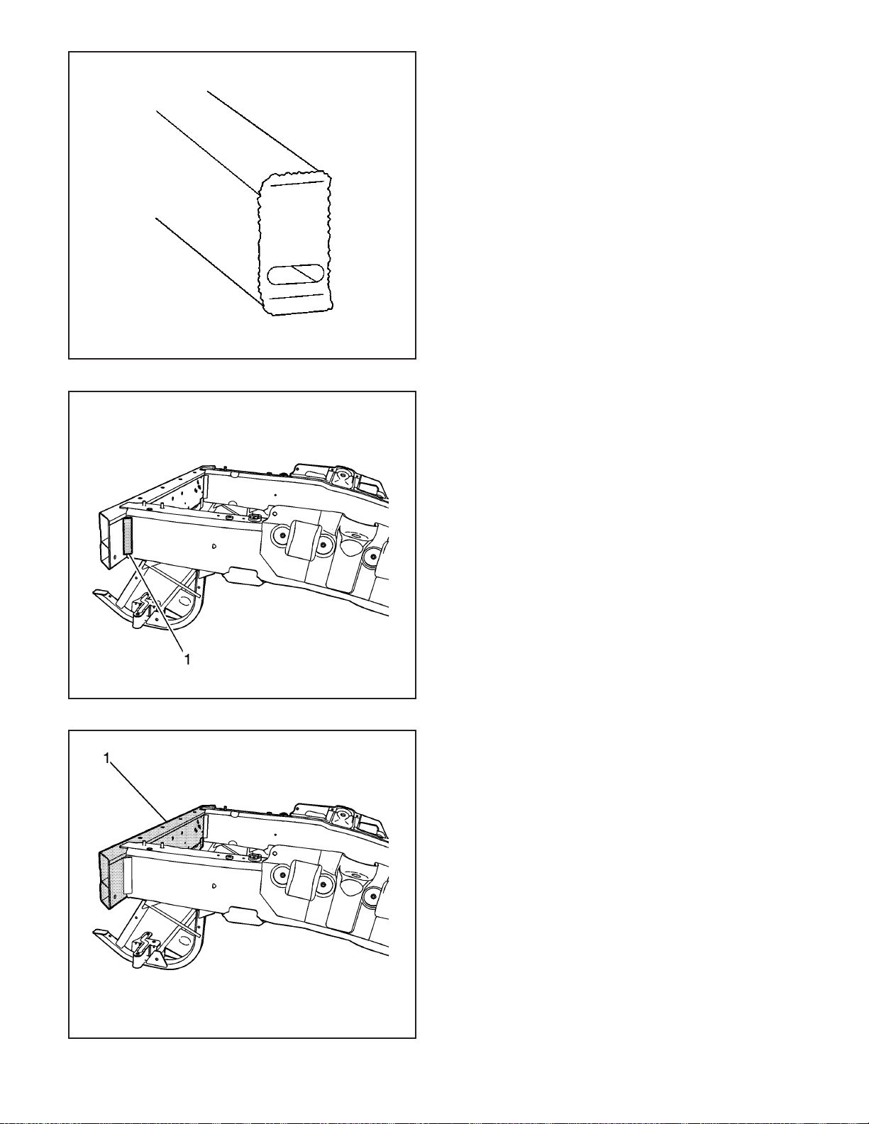
9. Remove pieces of the bumper bar which are left
attached to the rail ends.
10. Straighten and deburr the rail ends. Keep the
perimeter and shape of the rail end as original
as possible.
Installation Procedure
Important: Due to welding accessibility, it may be
necessary to weld the triangle brackets (1) to
the bumper bar prior to installation of the bumper bar.
1. Dry fit the bumper bar for proper fit and
alignment before welding.
Important: Use a stainless steel brush to remove the
oxide layer prior to welding.
2. Clean and prepare all of the welded mating
surfaces.
2-6 2006 Chevrolet Corvette Z06
1656612
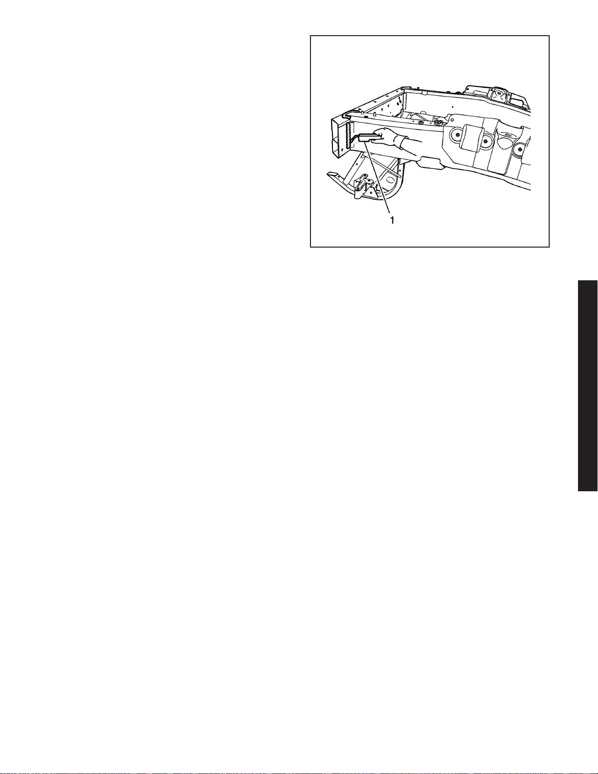
3. Install the front bumper bar (1).
4. Position the bumper bar to the vehicle using
3-dimensional measuring equipment.
1656635
Page 10
Important: Recommend wire alloy is 5356 and wire
size is.035. The shielding gas is 100 percent Argon.
A two minute cooling down period is recommend
for every 2 minutes or 100 mm (4 in) of welding.
5. Using a PULSED-MIG (P-MIG) welder, weld (1)
the bumper bar to the frame rail ends duplicating
the factory welds.
6. Apply the sealers and anti-corrosion materials to
the repair area. Refer to Anti-Corrosion Treatment
and Repair.
7. Paint the repair area. Refer to Basecoat/Clearcoat
Paint Systems.
8. Install all related panels and components.
9. Connect the negative battery cable. Refer to
Battery Negative Cable Disconnect/Connect
Procedure (7.0L) or Battery Negative Cable
Disconnect/Connect Procedure (6.0L).
10. Enable the SIR system. Refer to SIR Disabling
and Enabling Zones.
Hood Plate Stud Replacement (Z06)
Removal Procedure
The hood anchor plate assembly is riveted to the
inside of the front frame rail. Access to the hood plate
assembly would require the removal of the welded
front bumper bar. A procedure was developed for the
replacement of a broken hood stud without removing
the front bar.
Caution: Refer to Approved Equipment for
Collision Repair Caution on page 1-1.
1. Disable the SIR system. Refer to SIR Disabling
and Enabling Zones.
2. Disconnect the negative battery cable. Refer to
Battery Negative Cable Disconnect/Connect
Procedure (7.0L) or Battery Negative Cable
Disconnect/Connect Procedure (6.0L).
3. Remove all related panels and components.
4. Note the location and remove the sealers and
anti-corrosion materials from the repair area, as
necessary. Refer to Anti-Corrosion Treatment and
Repair.
5. Remove the hood hinge. Refer to Hood, Hinge,
Rod, Stud Replacement - Hood.
1656609
2006 Chevrolet Corvette Z06
2006 Chevrolet Corvette Z06 2-7
Page 11
1521166
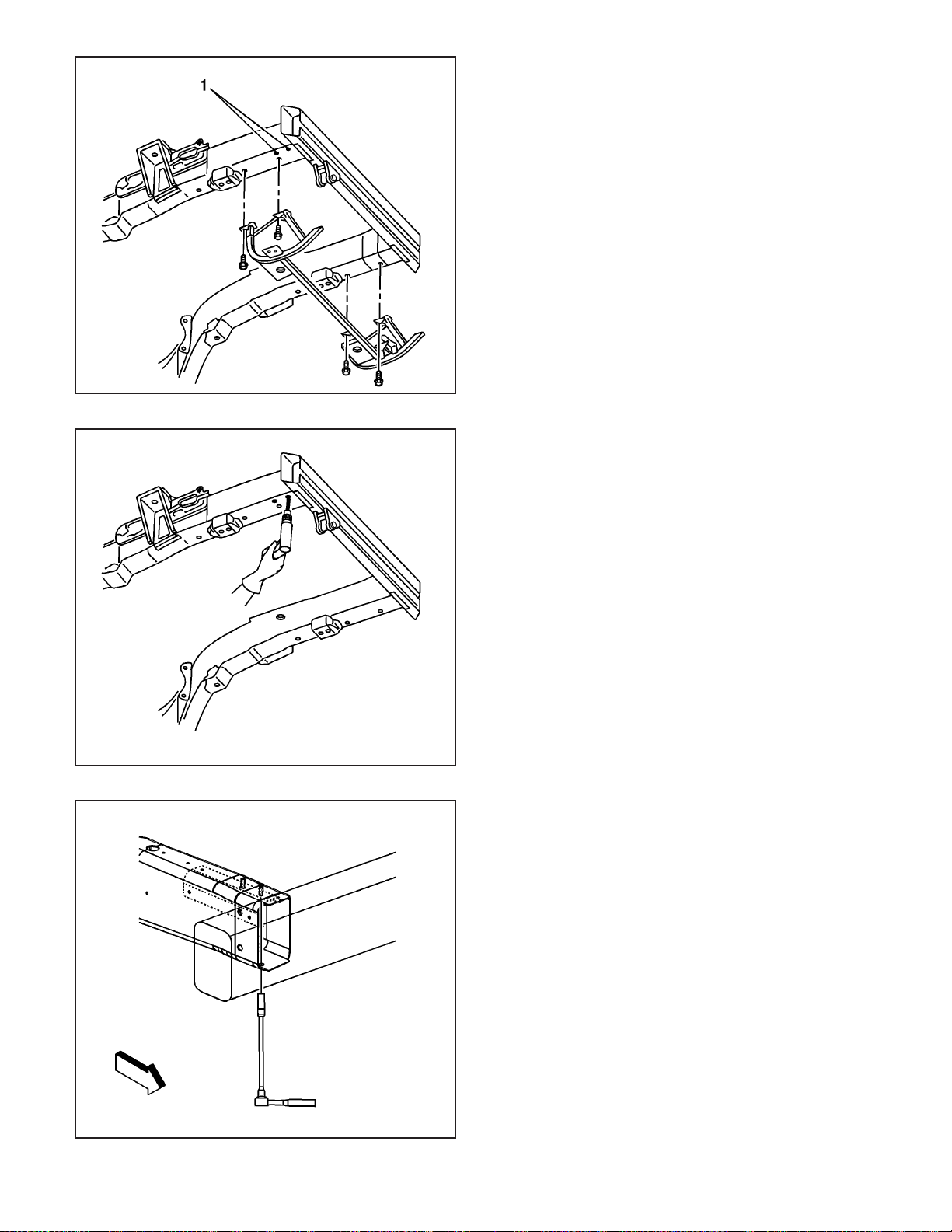
6. Locate the 2 pilot holes (1) directly below the front
and rear hood studs.
7. Drill a 25 mm (1 in) hole directly below the broken
hood stud.
2-8 2006 Chevrolet Corvette Z06
1521195
8. Install a socket and extension through the bottom
of the frame rail directly under the broken
hood stud.
1521206
Page 12
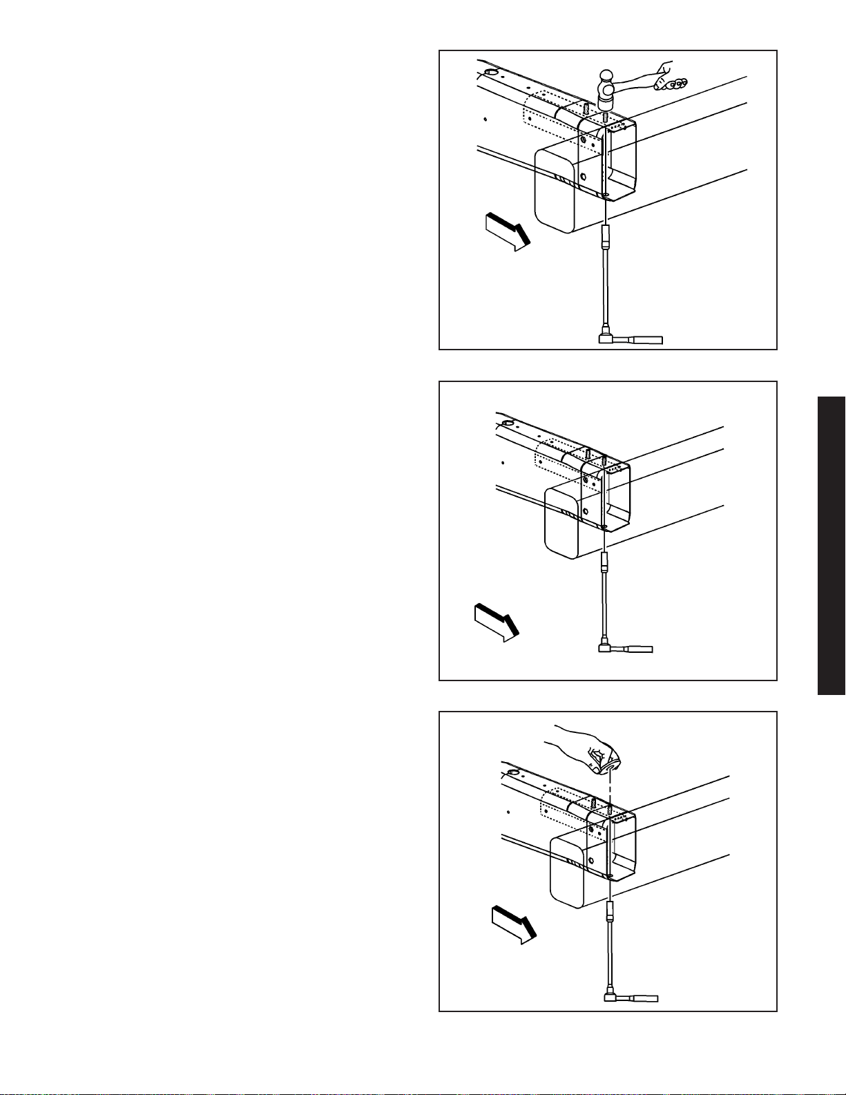
9. Using a hammer, tap the broken hood stud into
the socket.
10. Remove the broken hood stud.
Installation Procedure
Important: Replacement fasteners used with the Z06
aluminum frame requires a tin-zinc coating to
prevent galvanic corrosion.
1. Install a replacement bolt through the bottom of
the frame rail.
1521203
2. Install a retaining clip to the new bolt.
3. Install the hood hinge. Refer to Hood, Hinge, Rod,
Stud Replacement - Hood.
4. Paint the repaired area. Refer to
Basecoat/Clearcoat Paint Systems.
5. Apply the sealers and the anti-corrosion materials
to the repaired area, as necessary. Refer to
Anti-Corrosion Treatment and Repair.
6. Install all related panels and components.
7. Connect the negative battery cable. Refer to
Battery Negative Cable Disconnect/Connect
Procedure (7.0L) or Battery Negative Cable
Disconnect/Connect Procedure (6.0L).
8. Enable the SIR system. Refer to SIR Disabling
and Enabling Zones.
2006 Chevrolet Corvette Z06
1521206
1521224
2006 Chevrolet Corvette Z06 2-9
Page 13
1469679
Wheelhouse Replacement - Front (Z06)
Tools Required
J 42058 Frame Adapter Clamp
Removal Procedure
Caution: Refer to Approved Equipment for
Collision Repair Caution on page 1-1.
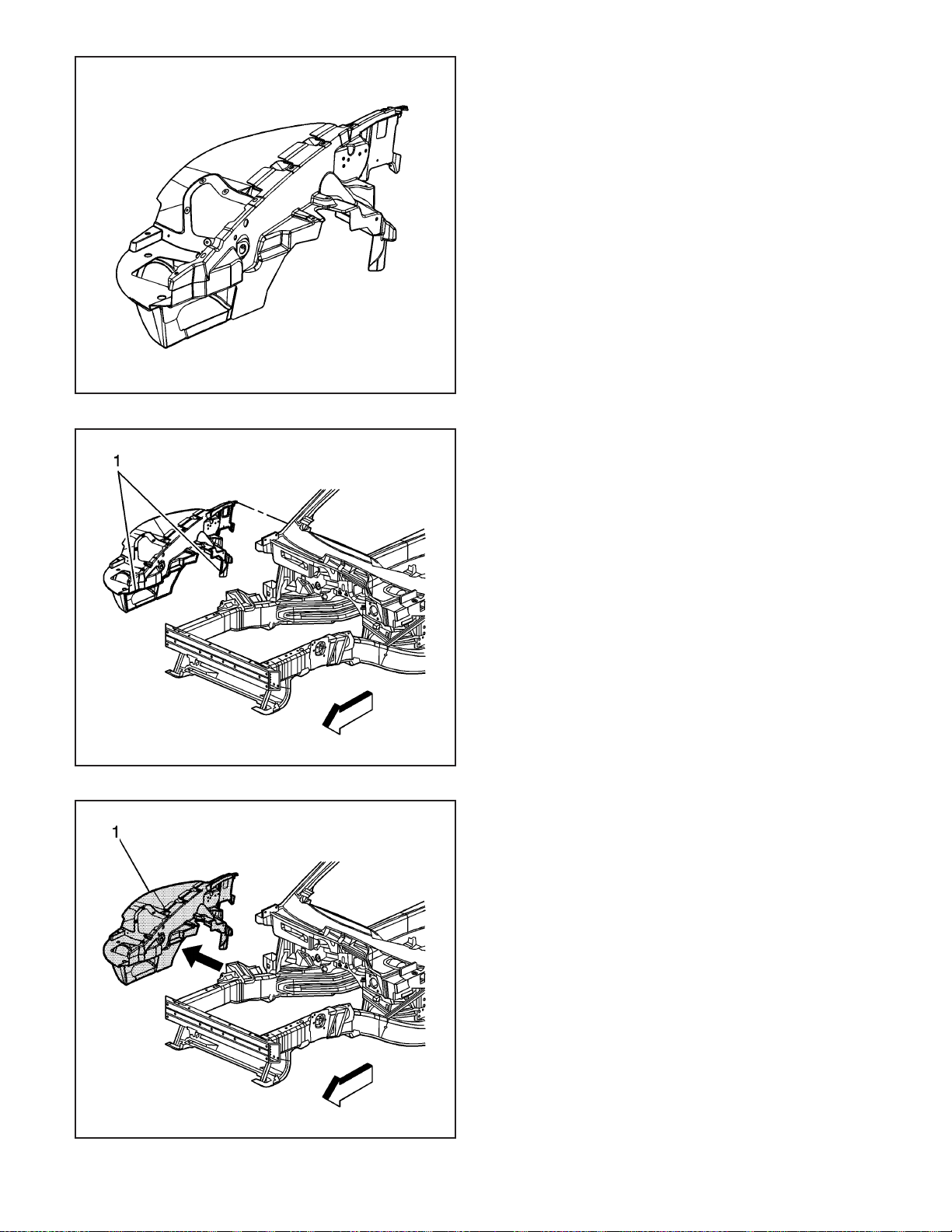
The front wheelhouse is comprised of 2 types of
materials. These include sheet molded
compound (SMC) for the inner panel and carbon fiber
for the outer panel. The wheelhouse is bonded to
the front structure and frame rail with structural
adhesive.
1. Disable the SIR system. Refer to SIR Disabling
and Enabling Zones.
2. Disconnect the negative battery cable. Refer to
Battery Negative Cable Disconnect/Connect
Procedure (7.0L) or Battery Negative Cable
Disconnect/Connect Procedure (6.0L).
3. Remove all related panels and components.
4. Remove the wheelhouse by applying heat and pry
to detach adhesive along the bonding surface (1).
2-10 2006 Chevrolet Corvette Z06
1469677
5. Remove the wheelhouse (1) from the vehicle.
6. Save any and all brackets, mounting studs, and
accessories for transfer to the new front
wheelhouse.
7. Note the location of the adhesive and remove all
remaining loose adhesive.
8. Inspect the front structure and frame rails for
damage.
9. Repair as much of the damage as possible to the
factory specifications.
10. Use J 42058 to secure the vehicle if pulling and
straightening is required.
1469681
Page 14
Installation Procedure
Important: Shims may be necessary to achieve
proper panel alignment.
1. Before applying adhesive dry fit the wheelhouse
for proper fit and alignment.
Important: DO NOT top coat any bonding surface.
Use primer only on bonding surfaces. Refer to
adhesive manufacturer’s recommendations.
2. Clean and prepare all bonding mating surfaces
according to adhesive manufacturer’s
recommendations.
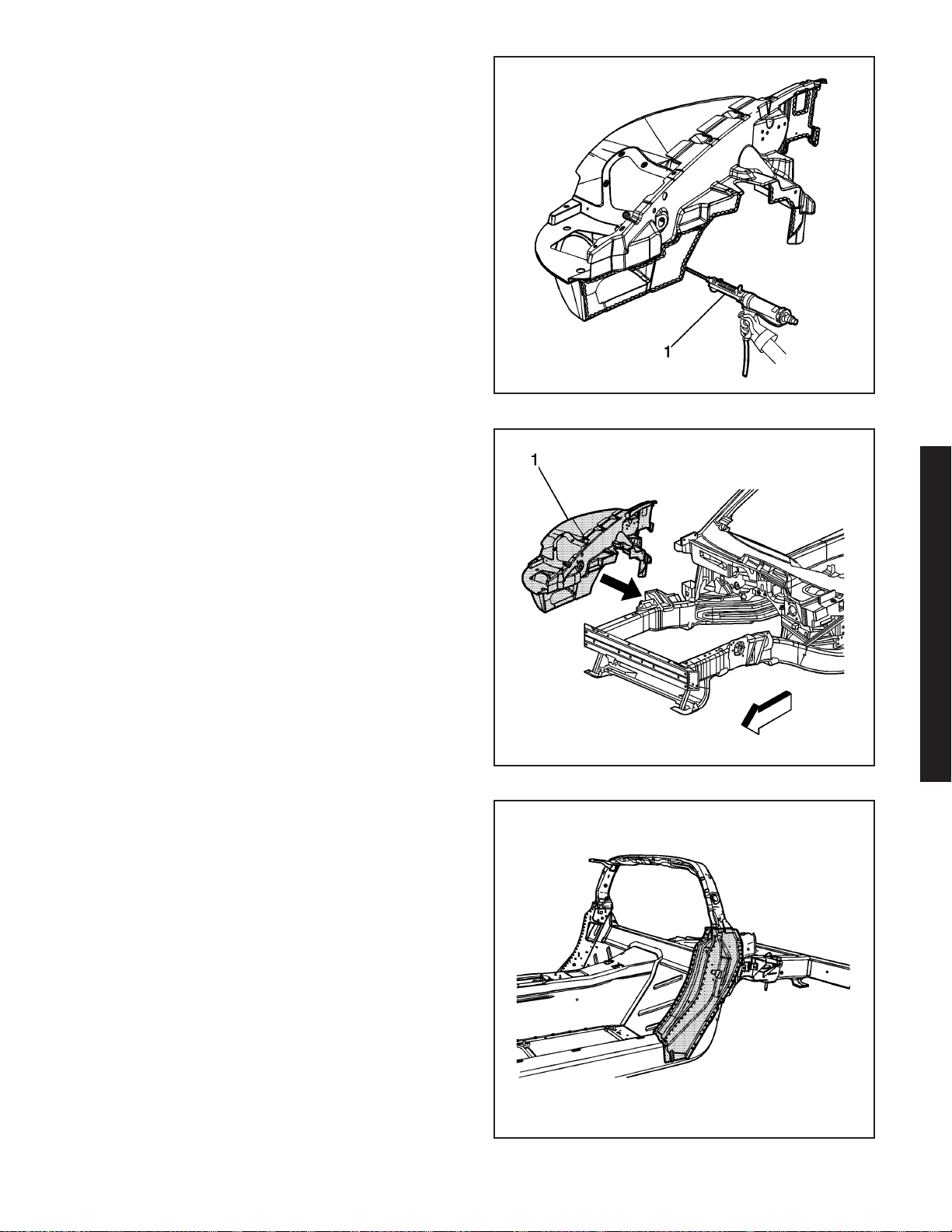
3. Apply a consistent bead of structural adhesive (1)
10 mm (3/8 in) in diameter to the wheelhouse to
mate with the front structure and frame rail.
Refer to Sheet Molded Compound (SMC) Panel
Bonding on page 2-62.
4. Install the wheelhouse (1) to the vehicle.
5. Apply pressure to the wheelhouse to set the
adhesive.
6. Clamp or mechanically fasten the wheelhouse into
place as necessary.
7. Remove any excess adhesive.
8. Install all related panels and components.
9. Connect the negative battery cable. Refer to
Battery Negative Cable Disconnect/Connect
Procedure (7.0L) or Battery Negative Cable
Disconnect/Connect Procedure (6.0L).
10. Enable the SIR system. Refer to SIR Disabling
and Enabling Zones.
1469868
Pillar Lock Front Door Replacement Outer (Z06)
Removal Procedure
The replacement outer lock pillar panel can be
serviced as an assembly or as the outer panel only.
Remove and replace the side door opening panel
in order to replace the outer lock pillar panel.
Caution: Refer to Approved Equipment for
Collision Repair Caution on page 1-1.
1. Disable the SIR system. Refer to SIR Disabling
and Enabling Zones.
2. Disconnect the negative battery cable. Refer to
Battery Negative Cable Disconnect/Connect
Procedure (7.0L) or Battery Negative Cable
Disconnect/Connect Procedure (6.0L).
2006 Chevrolet Corvette Z06
1469682
1664589
2006 Chevrolet Corvette Z06 2-11
Page 15
3. Remove all related panels and components.
4. Repair as much of the damage as possible to
factory specifications. Refer to Dimensions -
Body (Door Openings - Corvette) or Dimensions Body (Motor Compartment - Corvette) on
page 2-3 or Dimensions - Body (Z06) on page 2-4.
Caution: Refer to Sound Deadener Foam in
the Lock Striker Pillars Caution on page 1-1.
5. Note the location of the sealers and anti-corrosion
materials and remove these components from the
repair area as necessary. Refer to Anti-Corrosion
Treatment and Repair.
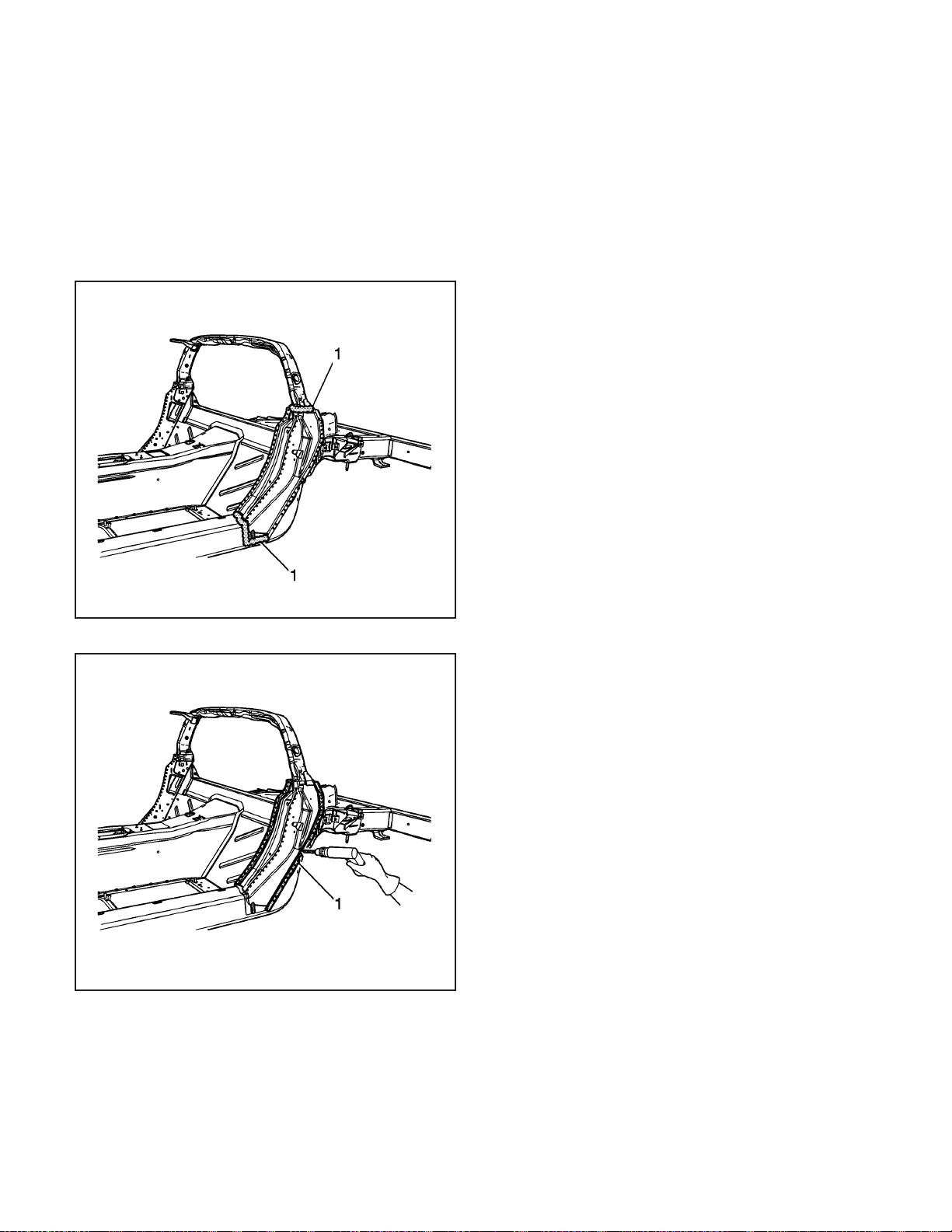
6. Locate and remove all factory welds (1). Note the
number and the location of the welds for
installation of the replacement part.
1664551
1664634
7. Using a drill (1) with a 6 mm (1/4 in) bit, locate
and remove all self-piercing rivets (SPR). Note the
number and location of the SPRs for installation
of the replacement part.
8. Remove the damaged outer lock pillar.
2-12 2006 Chevrolet Corvette Z06
Page 16
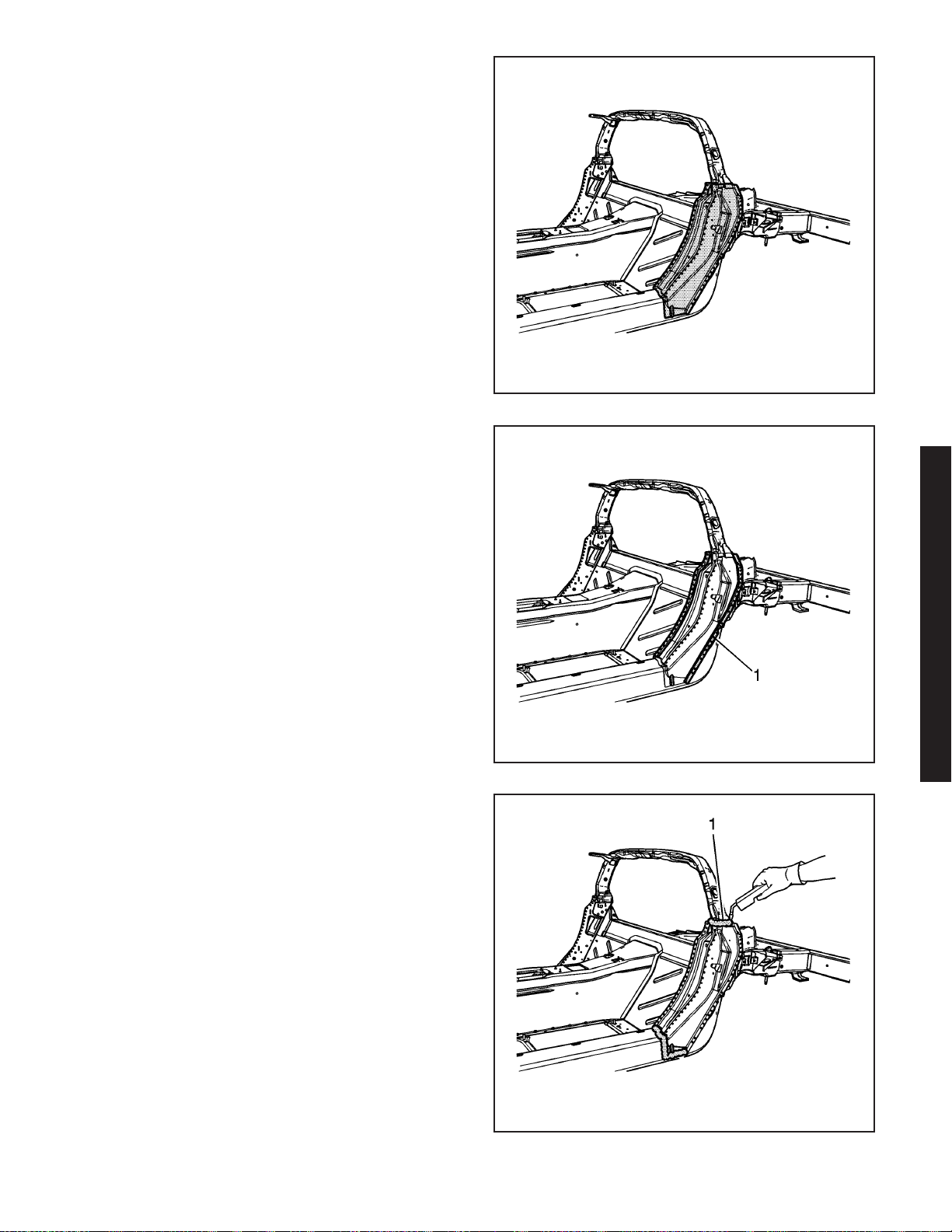
Installation Procedure
1. Position the outer lock pillar.
Important: Replace the SPRs with a structural
monobolt rivet, GM Part Number 19120691.
The structural monobolt rivet requires a special nose
tip, BO48073.
1664589
2. Drill 6 mm (1/4 in) holes in the service part as
necessary in the locations noted on the
original panel.
3. Using a rivet gun, attach the lock pillar with
structural monobolt rivets to the structure
duplicating the number of factory SPRs.
Important: Recommend wire alloy is 5356 and wire
size is.035. The shielding gas is 100% Argon.
A two minute cooling down period is recommend for
every 2 minutes or 100–mm (4–in) of welding.
4. Using a PULSED-MIG (P-MIG) welder, weld the
lock pillar to the structure duplicating the
factory welds.
5. Apply the sealers and the anti-corrosion materials
to the repair area, as necessary. Refer to
Anti-Corrosion Treatment and Repair.
6. Paint the repair area. Refer to Basecoat/Clearcoat
Paint Systems.
7. Install all related panels and components.
8. Connect the negative battery cable. Refer to
Battery Negative Cable Disconnect/Connect
Procedure (7.0L) or Battery Negative Cable
Disconnect/Connect Procedure (6.0L).
9. Enable the SIR system. Refer to SIR Disabling
and Enabling Zones.
2006 Chevrolet Corvette Z06
1664627
1664579
2006 Chevrolet Corvette Z06 2-13
Page 17

1657667
Impact Bar Replacement - Rear
Bumper (Z06)
Tools Required
J 42058 Frame Adapter Clamp
Removal Procedure
Caution: Refer to Approved Equipment for
Collision Repair Caution on page 1-1.
1. Disable the SIR system. Refer to SIR Disabling
and Enabling Zones.
2. Disconnect the negative battery cable. Refer to
Battery Negative Cable Disconnect/Connect
Procedure (7.0L) or Battery Negative Cable
Disconnect/Connect Procedure (6.0L).
3. Remove all related panels and components.
4. Repair as much of the damage as possible to the
factory specifications.
5. Use J 42058 to secure the vehicle if pulling and
straightening is required.
6. Note the location and remove the sealers and
anti-corrosion materials from the repair area.
Refer to Anti-Corrosion Treatment and Repair.
Important:
• Hand tools, saw blades and abrasives used for
aluminum repairs should be dedicated for
aluminum only to prevent contamination.
• When removing welds, favor the bumper bar side
of the weld joint.
7. Locate and remove all factory welds (1) attaching
the rear bumper bar to the bottom of the rear
frame rails. Note the location of the welds
for installation of the new bumper bar.
8. Locate and remove all factory welds (1) attaching
the rear bumper bar to the outer and inner of the
rear frame rails. Note the location of the welds
for installation of the new bumper bar.
2-14 2006 Chevrolet Corvette Z06
1657733
Page 18
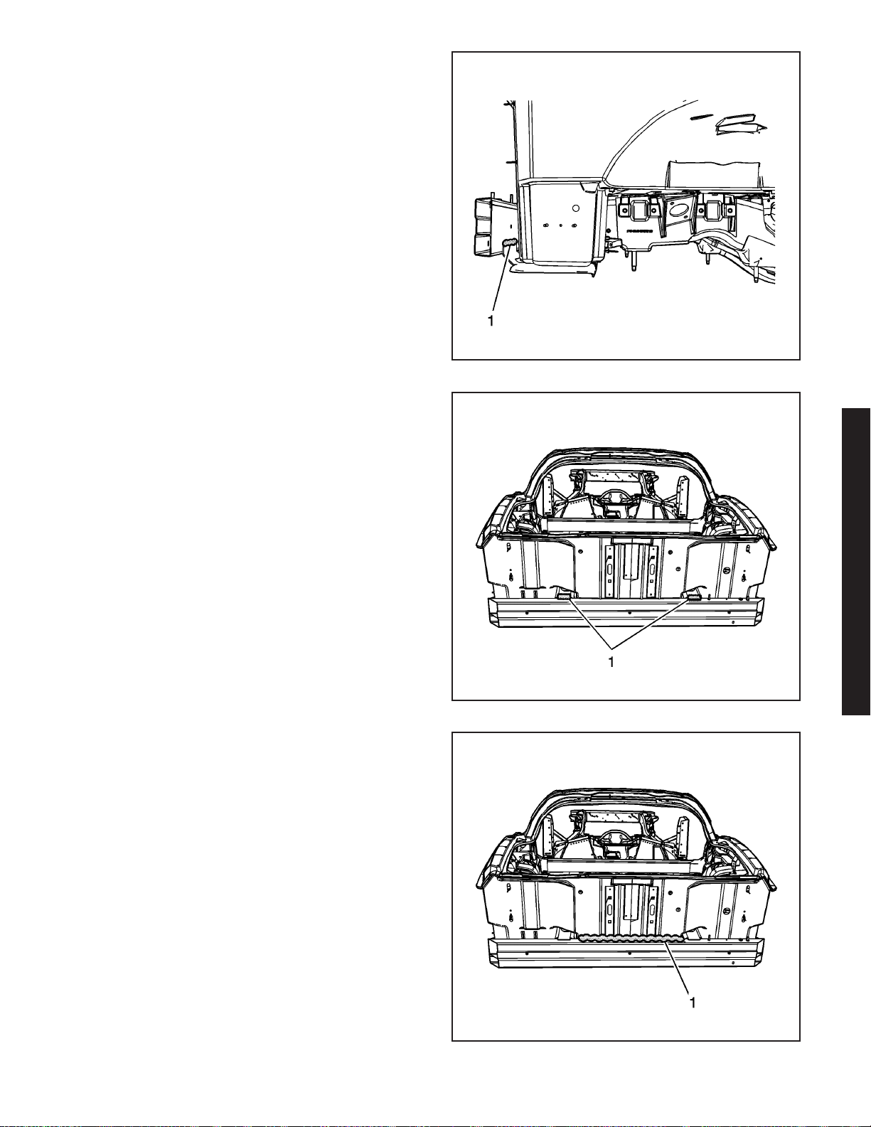
9. Locate and remove all factory welds (1) attaching
the rear bumper bar to the battery tray. Note the
location of the welds for installation of the new
bumper bar.
10. Locate and remove all factory welds (1) attaching
the rear bumper bar to the top of the rear frame
rails. Note the location of the welds for installation
of the new bumper bar.
1657666
11. Using a heat gun, detach the adhesive from the
rear bar (1) to the rear compartment panel.
12. Remove the damaged bumper bar.
2006 Chevrolet Corvette Z06
1657670
1657700
2006 Chevrolet Corvette Z06 2-15
Page 19
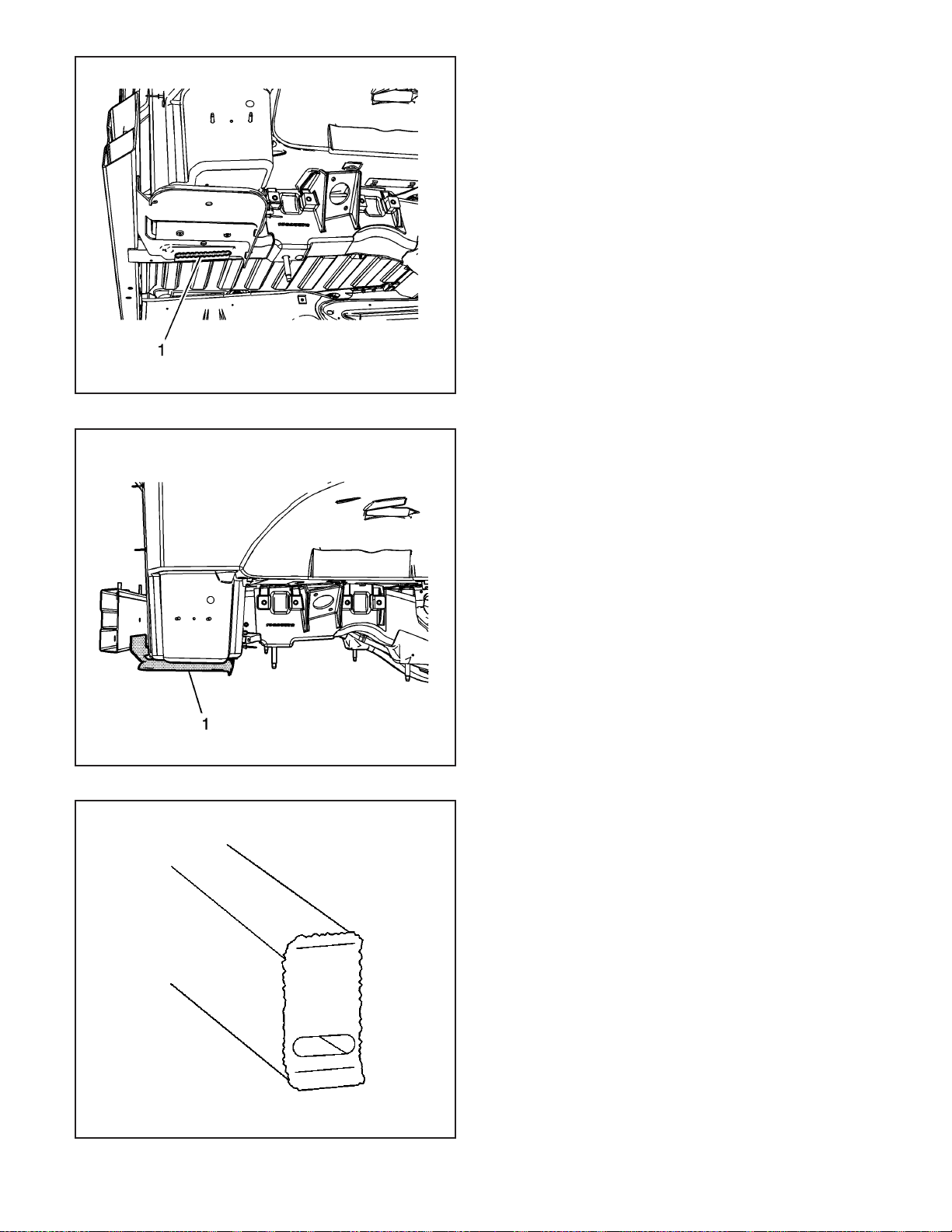
1657664
13. Locate and remove all factory welds (1) attaching
the battery tray to the battery tray bracket. Note
the location of the welds for installation of the
battery tray.
14. Using a heat gun, detach the adhesive from the
battery tray to the rear compartment panel.
15. Remove the battery tray (1).
2-16 2006 Chevrolet Corvette Z06
1657811
16. Remove pieces of the bumper bar which are left
attached to the rail ends.
17. Straighten and deburr the rail ends. Keep the
perimeter and shape of the rail end as original
as possible.
181153
Page 20
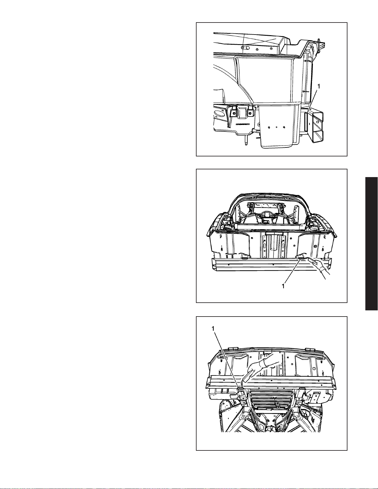
Installation Procedure
Important: Due to welding accessibility, it may be
necessary to weld the triangle brackets (1) to
the bumper bar prior to installation of the bumper bar.
1. Dry fit the bumper bar for proper fit and
alignment before welding.
Important: Use a stainless steel brush to remove the
oxide layer prior to welding.
2. Clean and prepare all of the welded mating
surfaces.
3. Install the rear bumper bar.
4. Position the bumper bar to the vehicle using
3-dimensional measuring equipment.
Important: Recommend wire alloy is 5356 and wire
size is.035. The shielding gas is 100% Argon.
A two minute cooling down period is recommend for
every 2 minutes or 100–mm (4–in) of welding.
1657668
5. Using a P-MIG welder, weld (1) the bumper bar to
the top of the rear frame rails duplicating the
factory welds.
6. Using a P-MIG welder, weld (1) the bumper bar to
the bottom of the rear frame rails duplicating the
factory welds.
2006 Chevrolet Corvette Z06
1657677
1657803
2006 Chevrolet Corvette Z06 2-17
Page 21
1657734
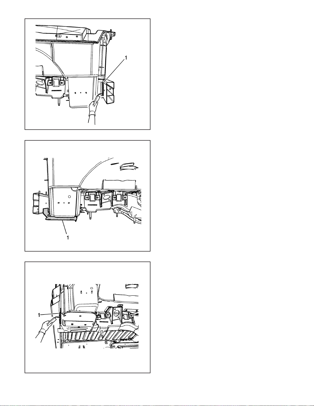
7. Using a P-MIG welder, weld (1) the bumper bar to
the outer and inner of the rear frame rails
duplicating the factory welds.
Important: DO NOT top coat the bonding surface of
the battery tray. Use primer only on bonding surfaces.
Refer to adhesive manufacturer’s recommendations.
8. Clean and prepare all bonding mating surfaces
according to adhesive manufacturer’s
recommendations.
9. Apply a consistent bead of structural adhesive to
the battery tray to bond to the rear compartment
panel. Refer to Sheet Molded Compound (SMC)
Panel Bonding on page 2-62.
10. install the battery tray (1).
11. Clamp or mechanically fasten the battery tray into
place as necessary.
2-18 2006 Chevrolet Corvette Z06
1657811
Important: Due to welding accessibility, it may be
necessary to change the weld location of the battery
tray to the rear bumper bar.
12. Using a P-MIG welder, weld (1) the battery tray to
the bottom of the bumper bar.
1657888
Page 22
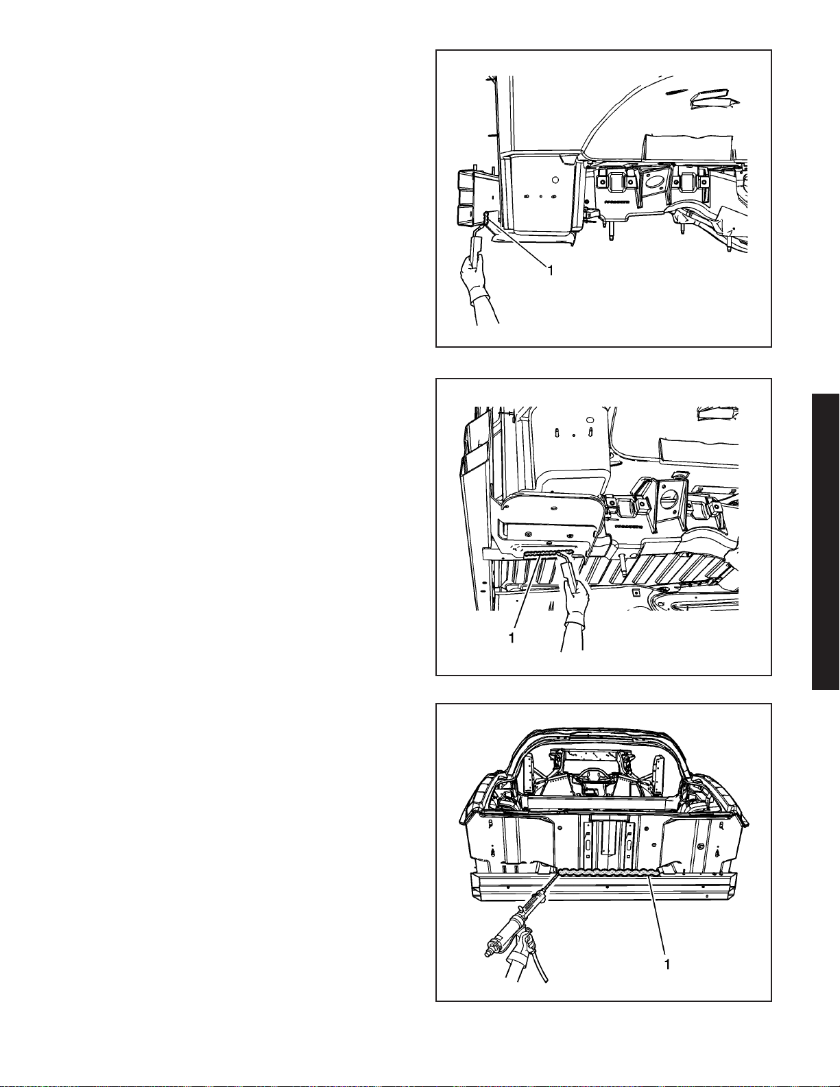
13. Using a P-MIG welder, weld (1) the outer edge of
the battery tray to the bumper bar.
14. Using a P-MIG welder, weld (1) the battery tray to
the battery tray bracket.
1657812
Important: DO NOT top coat the bonding surface of
the rear bar. Use primer only on bonding surfaces.
Refer to adhesive manufacturer’s recommendations.
15. Clean and prepare all bonding mating surfaces
according to adhesive manufacturer’s
recommendations.
16. Apply a consistent bead of structural adhesive to
the top impact bar to bond to the rear
compartment panel. Refer to Sheet Molded
Compound (SMC) Panel Bonding on page 2-62.
17. Apply the sealers and anti-corrosion materials to
the repair area. Refer to Anti-Corrosion Treatment
and Repair.
18. Paint the repair area. Refer to Basecoat/Clearcoat
Paint Systems.
19. Install all related panels and components.
2006 Chevrolet Corvette Z06
1657880
1657681
2006 Chevrolet Corvette Z06 2-19
Page 23
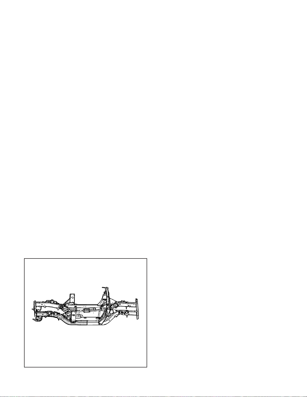
20. Connect the negative battery cable. Refer to
Battery Negative Cable Disconnect/Connect
Procedure (7.0L) or Battery Negative Cable
Disconnect/Connect Procedure (6.0L).
21. Enable the SIR system. Refer to SIR Disabling
and Enabling Zones.
Rail Replacement - Front (Z06)
Tools Required
J 42058 Frame Adapter Clamp
Removal Procedure
The service rails are complete rail assemblies for the
left and the right sides, 6063–T7, hydro-formed
aluminum parts.
Caution: Refer to Approved Equipment for
Collision Repair Caution on page 1-1.
1. Disable the SIR system. Refer to SIR Disabling
and Enabling Zones.
2. Disconnect the negative battery cable. Refer to
Battery Negative Cable Disconnect/Connect
Procedure (7.0L) or Battery Negative Cable
Disconnect/Connect Procedure (6.0L).
3. Remove all related panels and components.
4. Remove the front impact bar. Refer to Impact Bar
Replacement - Front Bumper (Corvette) or Impact
Bar Replacement - Front Bumper (Z06) on
page 2-5.
5. Note the location and remove the sealers and
anti-corrosion materials from the repair area.
Refer to Anti-Corrosion Treatment and Repair.
6. Repair as much of the damage as possible to the
factory specifications.
7. Use J 42058 to secure the vehicle if pulling and
straightening is required.
8. Inspect the front of the dash panel, floor panels,
and all other sheet molded compound (SMC) and
carbon fiber for cracks or areas that may need
to be repaired or resealed.
9. Remove the damaged section of frame rail.
2-20 2006 Chevrolet Corvette Z06
1655993
Page 24
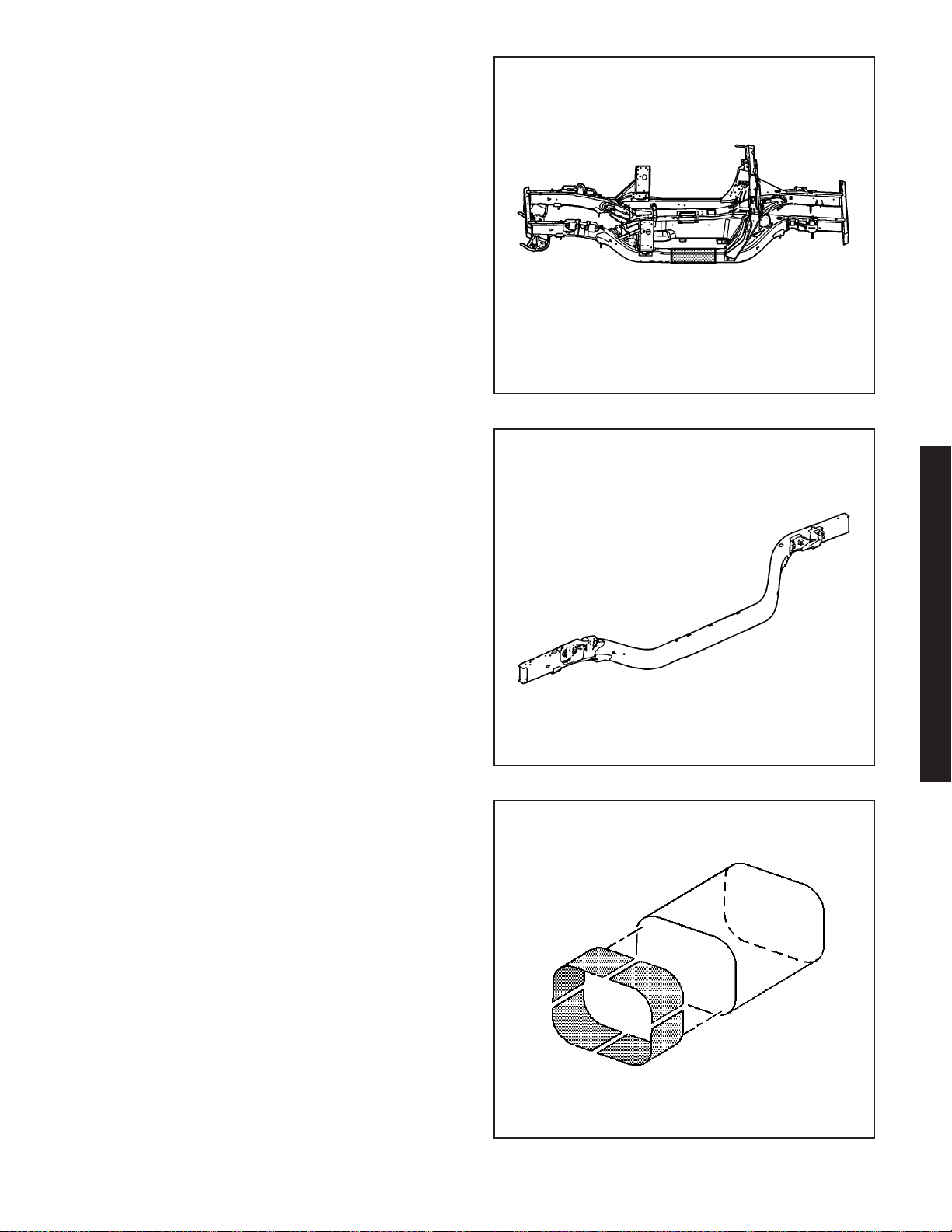
Installation Procedure
Caution: Refer to Collision Sectioning Caution on
page 1-1.
1. Determine the sectioning joint location within the
recommended area.
2. Cut the new frame section from the new frame rail
assembly.
1655985
3. Perform the sleeved butt-joint sectioning. Refer to
Sleeved Butt Joint Repair (Corvette) or Sleeved
Butt Joint Repair (Z06) on page 2-36.
4. Install the front impact bar. Refer to Impact Bar
Replacement - Front Bumper (Corvette) or
Impact Bar Replacement - Front Bumper (Z06) on
page 2-5.
5. Apply the sealers and anti-corrosion materials to
the repair area. Refer to Anti-Corrosion Treatment
and Repair.
6. Paint the repair area. Refer to Basecoat/Clearcoat
Paint Systems.
7. Install all related panels and components.
8. Connect the negative battery cable. Refer to
Battery Negative Cable Disconnect/Connect
Procedure (7.0L) or Battery Negative Cable
Disconnect/Connect Procedure (6.0L).
9. Enable SIR system. Refer to SIR Disabling and
Enabling Zones.
2006 Chevrolet Corvette Z06
1654842
857910
2006 Chevrolet Corvette Z06 2-21
Page 25

1545632
1545712
Rail Replacement - Front Section (Z06)
Tools Required
J 42058 Frame Adapter Clamp
Removal Procedure
The service rails are complete rail assemblies for the
left and the right sides, 6063–T7, hydro-formed
aluminum parts, which correlate directly with the die
mark (1) located on the front frame rails
Caution: Refer to Approved Equipment for
Collision Repair Caution on page 1-1.
1. Disable the SIR system. Refer to SIR Disabling
and Enabling Zones.
2. Disconnect the negative battery cable. Refer to
Battery Negative Cable Disconnect/Connect
Procedure (7.0L) or Battery Negative Cable
Disconnect/Connect Procedure (6.0L).
3. Remove all related panels and components.
4. Remove the front impact bar. Refer to Impact Bar
Replacement - Front Bumper (Corvette) or Impact
Bar Replacement - Front Bumper (Z06) on
page 2-5.
5. Note the location and remove the sealers and
anti-corrosion materials from the repair area, as
necessary. Refer to Anti-Corrosion Treatment and
Repair.
6. Repair as much of the damage as possible to the
factory specifications.
7. Use J 42058 to secure the vehicle if pulling and
straightening is required.
8. Inspect the front of the dash panel, floor panels,
and all other sheet molded compound (SMC) and
carbon fiber for cracks or areas that may need
to be repaired or resealed.
Important: Hand tools, saw blades and abrasives
used for aluminum repairs should be dedicated
for aluminum only to prevent contamination.
9. Locate and remove all factory welds attaching the
upper extension panel (1) to the structure. Note
the location of the welds for installation of the
upper extension panel.
10. Locate and remove all factory self-piercing
rivets (SPR) attaching the upper extension
panel to the structure. Note the location and
number of SPRs for re-installation of the upper
extension panel.
11. Remove the upper extension panel (1).
Remove the front floor panel.
2-22 2006 Chevrolet Corvette Z06
Page 26
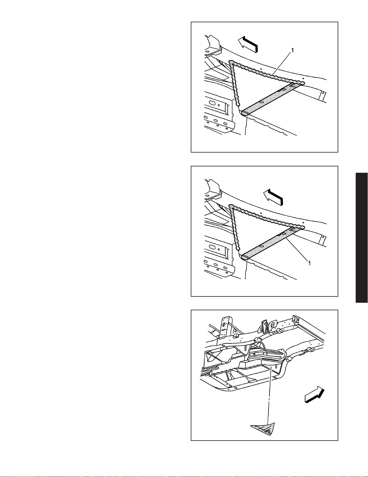
12. Locate and remove all factory welds (1) attaching
the lower extension panel to the structure. Note
the location of the welds for installation of the
lower extension panel.
13. Locate and remove all factory SPRs (1) attaching
the lower extension panel to the structure. Note
the location and number of SPRs for reinstallation of the lower extension panel.
1549188
14. Remove the lower extension panel.
2006 Chevrolet Corvette Z06
1549177
1549637
2006 Chevrolet Corvette Z06 2-23
Page 27
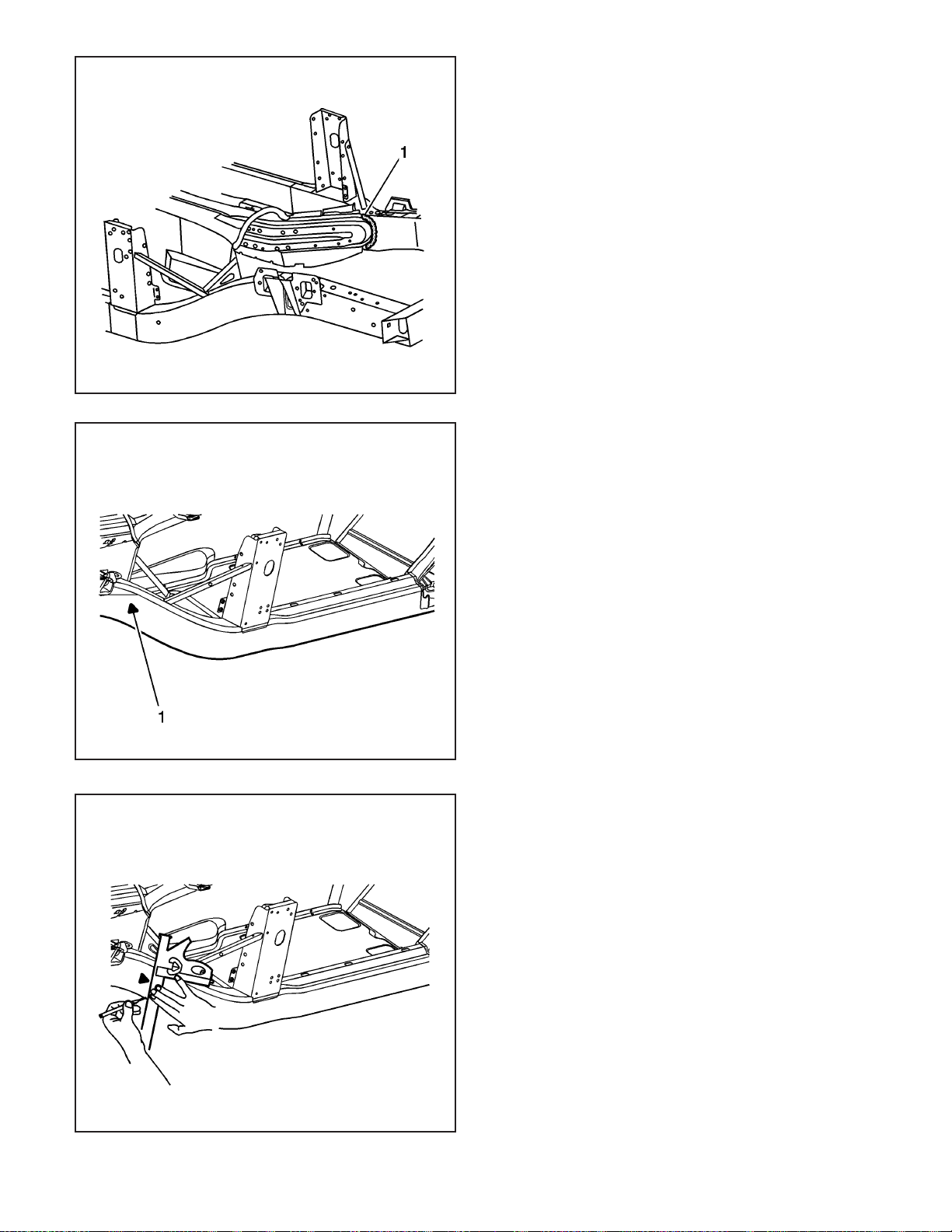
1546697
15. Locate and remove all factory welds (1) attaching
the 2 tunnel braces to the frame rail. Note the
location of the welds for installation of the tunnel
braces. Make cuts favoring the frame rail side
of the welds.
Caution: Refer to Collision Sectioning Caution on
page 1-1.
16. Locate the die-mark (1) on the damaged
frame rail.
2-24 2006 Chevrolet Corvette Z06
1549858
17. At the die mark align a sliding square or similar
tool square to surface to the vertical walls of the
frame rail.
18. Scribe a line to both sides of the frame rail.
1549753
Page 28
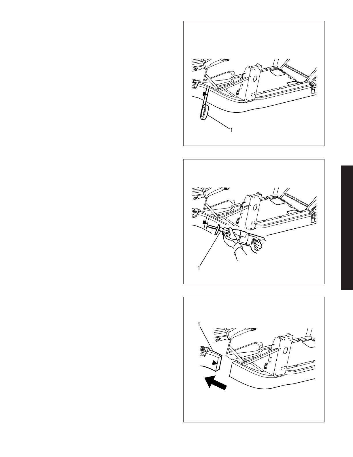
19. Apply masking tape (1) to the scribe line
completely around the frame rail.
20. Cut the frame rail at the rear edge of the tape line
using a reciprocating saw (1) or equivalent tool.
1549642
21. Remove the damaged frame rail section (1).
2006 Chevrolet Corvette Z06
1549847
1549927
2006 Chevrolet Corvette Z06 2-25
Page 29
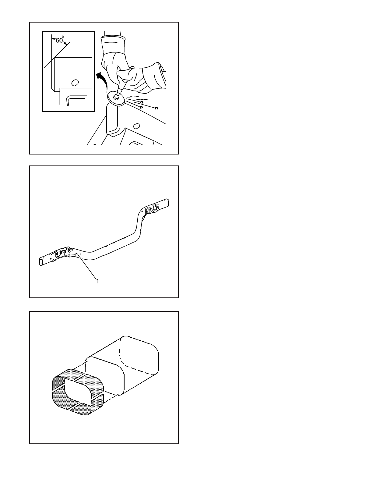
1545467
Installation Procedure
1. Grind the existing frame rail sectioning location to
a 60 degree angle.
Caution: Refer to Collision Sectioning Caution on
page 1-1.
2. Locate the die-mark on the service frame rail.
3. Cut the new frame section from the service frame
rail assembly.
2-26 2006 Chevrolet Corvette Z06
1576956
4. Perform the sleeved butt-joint sectioning. Refer to
Sleeved Butt Joint Repair (Corvette) or Sleeved
Butt Joint Repair (Z06) on page 2-36.
Important: Use a stainless steel brush to remove the
oxide layer prior to welding.
5. Clean and prepare all of the welded mating
surfaces.
857910
Page 30
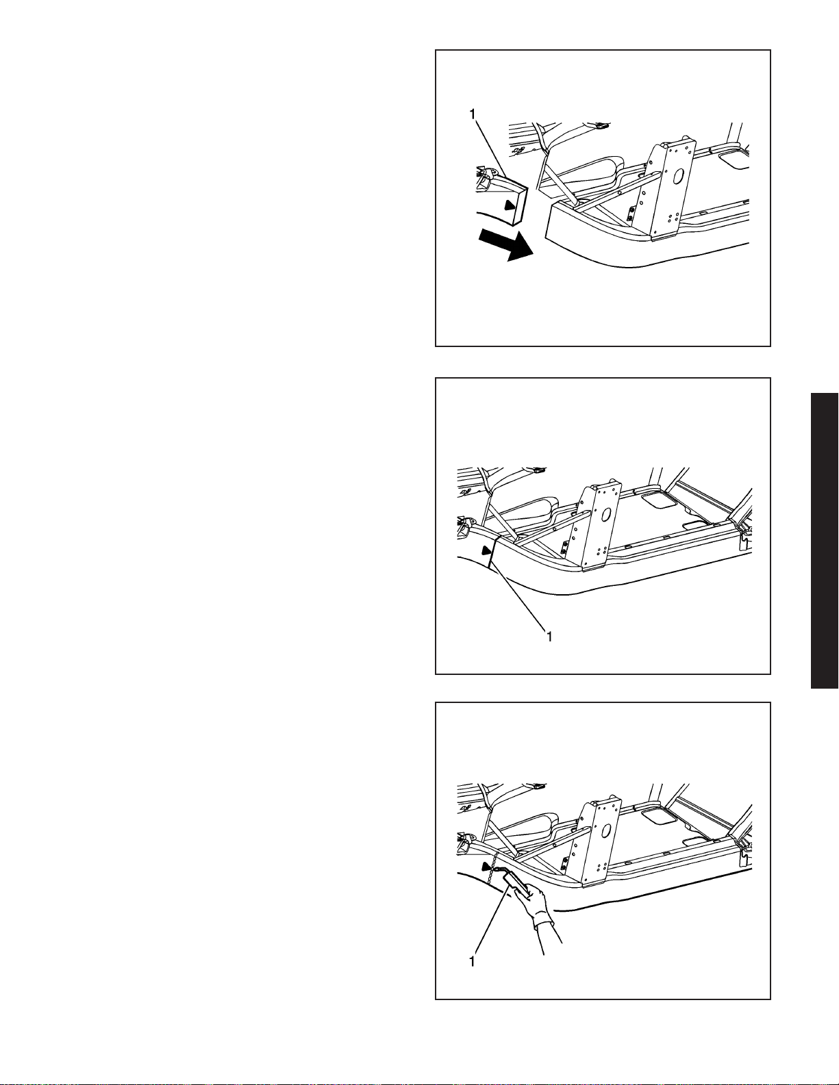
6. Position the service frame section (1) to the
existing frame.
7. Maintain a gap of one frame rail metal thickness
at the sectioning joint (1) and clamp in place.
8. Inspect the frame measurements
three-dimensional to ensure proper position of the
service frame section.
1575870
Important: Recommend 2 weld passes (root and cap).
Recommend wire alloy is 5356 and wire size is 0.035.
The shielding gas is 100 percent Argon.
A 2 minute cooling down period is recommend for
every 2 minutes or 100 mm (4 in) of welding.
9. Using a PULSED-MIG (P-MIG) welder, weld
50-mm (2-in) stitch welds to the top and bottom
of the sleeve joint.
10. Using a P-MIG welder, weld (1) 50-mm (2-in)
welds to the inner and outer vertical walls of
the sleeve joint.
11. Inspect the frame measurements
three-dimensional to ensure proper position of the
service frame section.
12. Using a P-MIG welder, complete the welding of
the sleeve joint using the 2 minute cooling down
period for every 2 minutes or 100 mm (4 in)
of welding.
2006 Chevrolet Corvette Z06
1576359
1549963
2006 Chevrolet Corvette Z06 2-27
Page 31
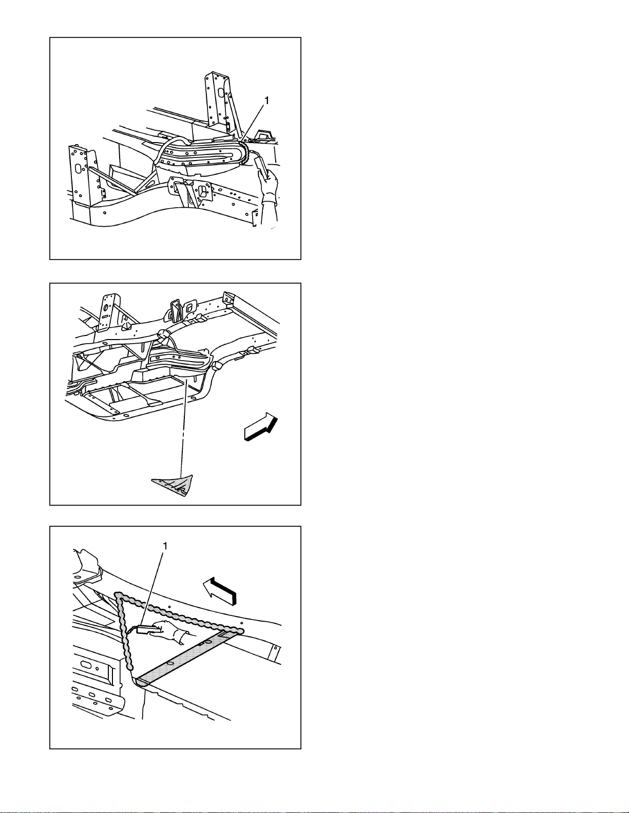
1576355
Important: A 2 minute cooling down period is
recommend for every 2 minutes or 100 mm (4 in) of
welding.
13. Using a P-MIG welder, stitch weld (1) the tunnel
braces to the structure duplicating the
factory welds.
14. Install the lower extension panel.
2-28 2006 Chevrolet Corvette Z06
1549637
Important: A 2 minute cooling down period is
recommend for every 2 minutes or 100 mm (4 in) of
welding.
15. Using a P-MIG welder, stitch weld (1) the lower
floor extension panel to the structure duplicating
the factory welds.
Important: Replace the SPRs with a structural
monobolt rivet, GM Part Number 19120691.
The structural monobolt rivet requires a special nose
tip, BO48073.
16. Using a rivet gun, attach the lower floor extension
panel to the structure duplicating the number of
factory SPRs.
1550023
Page 32
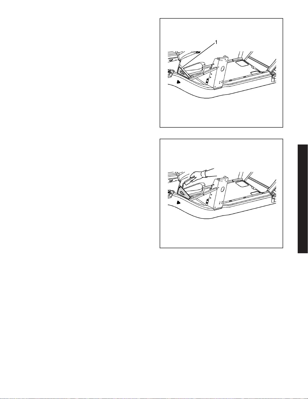
17. Install the upper extension panel (1).
18. Using a P-MIG welder, weld the upper extension
panel to the structure duplicating the factory welds.
Important: Replace the SPRs with a structural
monobolt rivet, GM Part Number 19120691.
The structural monobolt rivet requires a special nose
tip, BO48073.
19. Using a rivet gun, attach the upper floor extension
panel to the structure duplicating the number of
factory SPRs.
20. Install the front impact bar. Refer to Impact Bar
Replacement - Front Bumper (Corvette) or
Impact Bar Replacement - Front Bumper (Z06) on
page 2-5.
21. Apply the sealers and anti-corrosion materials to
the repair area, as necessary. Refer to
Anti-Corrosion Treatment and Repair.
22. Paint the repair area. Refer to Basecoat/Clearcoat
Paint Systems.
23. Install all related panels and components.
24. Connect the negative battery cable. Refer to
Battery Negative Cable Disconnect/Connect
Procedure (7.0L) or Battery Negative Cable
Disconnect/Connect Procedure (6.0L).
25. Enable the SIR system. Refer to SIR Disabling
and Enabling Zones.
1545712
2006 Chevrolet Corvette Z06
1550046
2006 Chevrolet Corvette Z06 2-29
Page 33
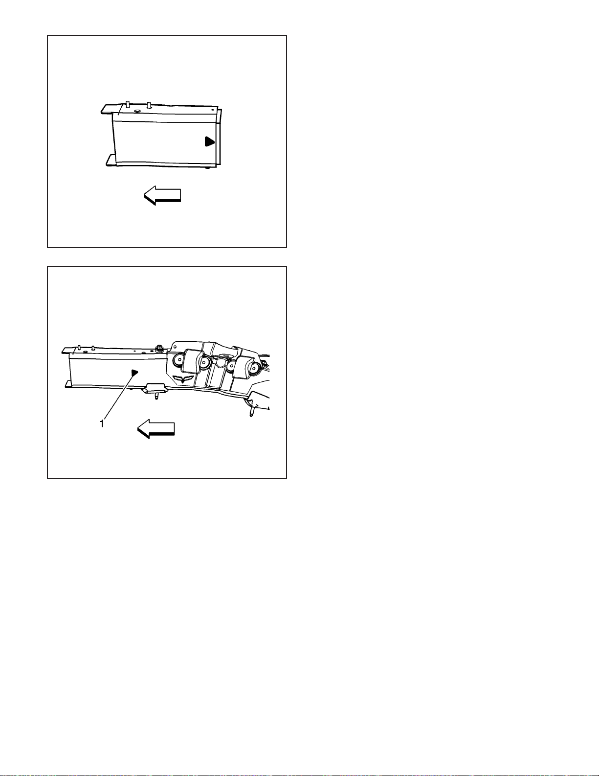
1545452
1631306
Rail End Replacement - Front (Z06)
Tools Required
J 42058 Frame Adapter Clamp
Removal Procedure
The service assemblies for the left and the right front
end frame rails are pre-sleeved, 6063–T7 aluminum,
hydro-formed parts, which correlate directly with
the die mark located on the front frame rails.
Caution: Refer to Approved Equipment for
Collision Repair Caution on page 1-1.
1. Disable the SIR system. Refer to SIR Disabling
and Enabling Zones.
2. Disconnect the negative battery cable. Refer to
Battery Negative Cable Disconnect/Connect
Procedure (7.0L) or Battery Negative Cable
Disconnect/Connect Procedure (6.0L).
3. Remove all related panels and components.
4. Remove the front impact bar. Refer to Impact Bar
Replacement - Front Bumper (Corvette) or Impact
Bar Replacement - Front Bumper (Z06) on
page 2-5.
5. Note the location and remove the sealers and
anti-corrosion materials from the repair area.
Refer to Anti-Corrosion Treatment and Repair.
6. Repair as much of the damage as possible to the
factory specifications.
7. Use J 42058 to secure the vehicle if pulling and
straightening is required.
Caution: Refer to Collision Sectioning Caution on
page 1-1.
8. Locate the die-mark (1) on the damaged
frame rail.
2-30 2006 Chevrolet Corvette Z06
Page 34
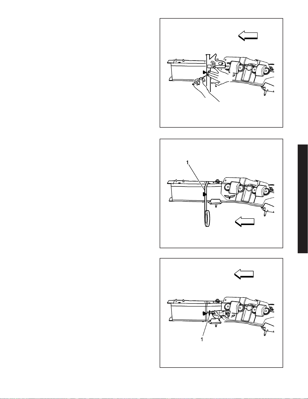
9. At the die mark align a sliding square or similar
tool square to surface to the vertical walls of the
frame rail.
10. Scribe a line to both sides of the frame rail.
11. Apply masking tape (1) to the scribe line
completely around the frame rail.
1631305
Important: Hand tools, saw blades and abrasives
used for aluminum repairs should be dedicated for
aluminum only to prevent contamination.
12. Cut the frame rail at the rear edge of the tape line
using a reciprocating saw or equivalent tool (1).
2006 Chevrolet Corvette Z06
1631303
1631300
2006 Chevrolet Corvette Z06 2-31
Page 35
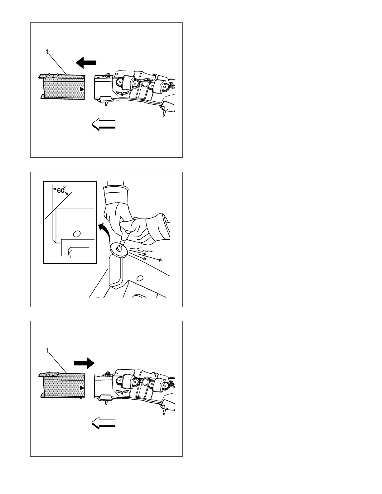
1545461
13. Remove the damaged frame rail end section (1).
Installation Procedure
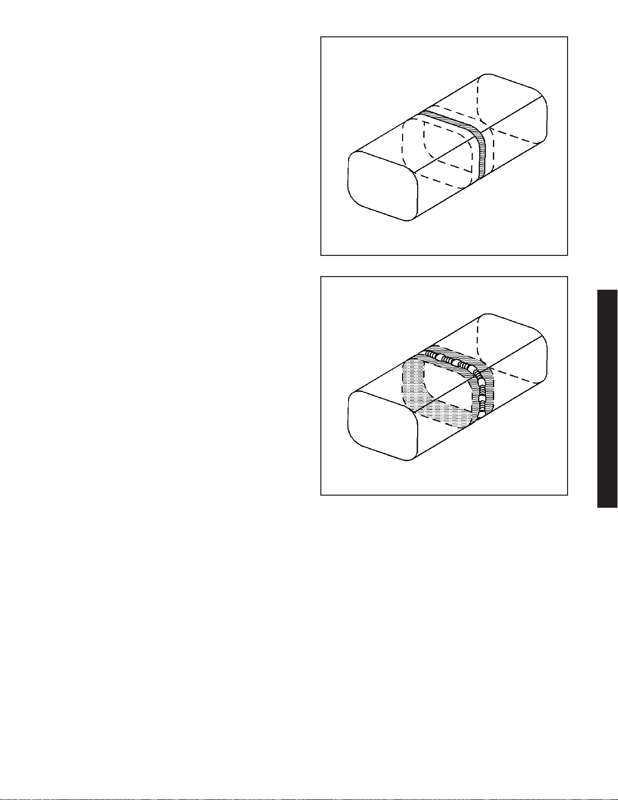
1. Grind the existing frame rail sectioning location to
a 60 degree angle.
Important: Use a stainless steel brush to remove the
oxide layer prior to welding.
2. Clean and prepare all of the welded mating
surfaces.
2-32 2006 Chevrolet Corvette Z06
1545467
3. Position the service frame section (1) to the
existing frame.
1545469
Page 36
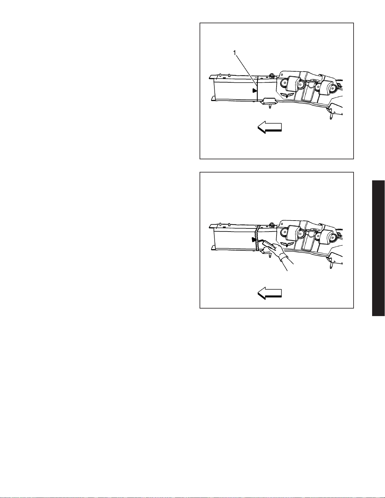
4. Maintain a gap of one frame rail metal thickness
at the sectioning joint (1) and clamp in place.
5. Inspect the frame measurements
three-dimensional to ensure proper position of the
service frame section.
Important:
• Recommend 2 weld passes (root and cap).
• Recommend wire alloy is 5356 and wire size is
0.035. The shielding gas is 100 percent Argon.
• A 2 minute cooling down period is recommend for
every 2 minutes or 100 mm (4 in) of welding.
6. Using a PULSED-MIG welder, weld 50 mm (2 in)
stitch welds to the top and bottom of the
sleeve joint.
7. Using a PULSED-MIG welder, weld 50 mm (2 in)
stitch welds to the inner and outer vertical walls of
the sleeve joint.
8. Inspect the frame measurements
three-dimensional to ensure proper position of the
service frame section.
9. Using a PULSED-MIG welder, complete the
welding of the sleeve joint using the 2 minute
cooling down period for every 2 minutes or
100 mm (4 in) of welding.
10. Install the front impact bar. Refer to Impact Bar
Replacement - Front Bumper (Corvette) or
Impact Bar Replacement - Front Bumper (Z06) on
page 2-5.
11. Apply the sealers and anti-corrosion materials to
the repair area. Refer to Anti-Corrosion Treatment
and Repair.
Important: DO NOT top coat any bonding surface.
Use primer only on bonding surfaces. Refer to
adhesive manufacturer’s recommendations.
12. Paint the repair area. Refer to Basecoat/Clearcoat
Paint Systems.
13. Install all related panels and components.
14. Connect the negative battery cable. Refer to
Battery Negative Cable Disconnect/Connect
Procedure (7.0L) or Battery Negative Cable
Disconnect/Connect Procedure (6.0L).
15. Enable the SIR system. Refer to SIR Disabling
and Enabling Zones.
1631286
2006 Chevrolet Corvette Z06
1631296
2006 Chevrolet Corvette Z06 2-33
Page 37
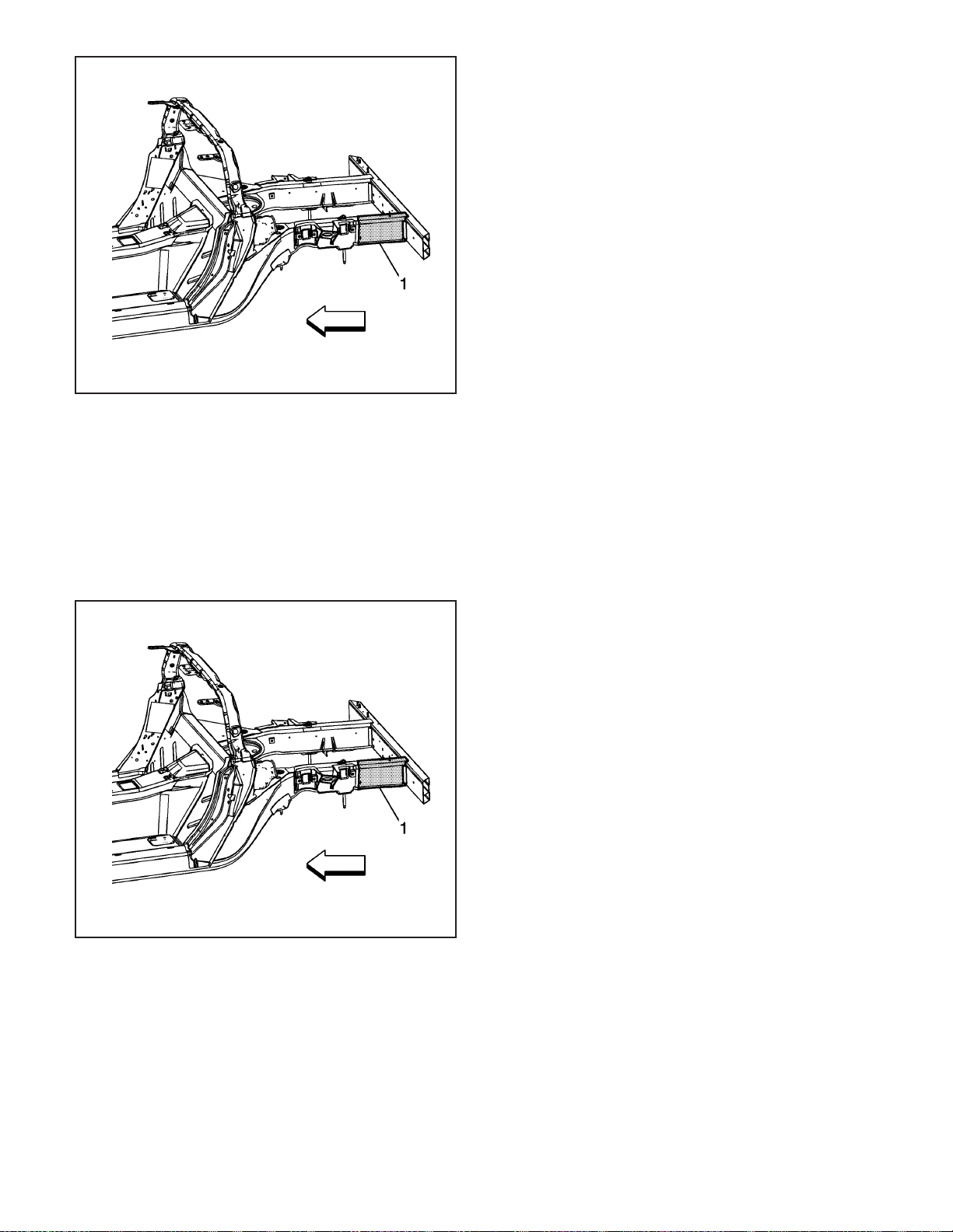
1654759
Rail End Replacement - Rear (Z06)
Tools Required
J 42058 Frame Adapter Clamp
Removal Procedure
Caution: Refer to Approved Equipment for
Collision Repair Caution on page 1-1.
1. Disable the SIR system. Refer to SIR Disabling
and Enabling Zones.
2. Disconnect the negative battery cable. Refer to
Battery Negative Cable Disconnect/Connect
Procedure (7.0L) or Battery Negative Cable
Disconnect/Connect Procedure (6.0L).
3. Remove all related panels and components.
4. Remove the rear impact bar. Refer to Impact Bar
Replacement - Rear Bumper (Corvette) or Impact
Bar Replacement - Rear Bumper (Z06) on
page 2-14.
5. Note the location and remove the sealers and
anti-corrosion materials from the repair area.
Refer to Anti-Corrosion Treatment and Repair.
6. Repair as much of the damage as possible to the
factory specifications.
7. Use J 42058 to secure the vehicle if pulling and
straightening is required.
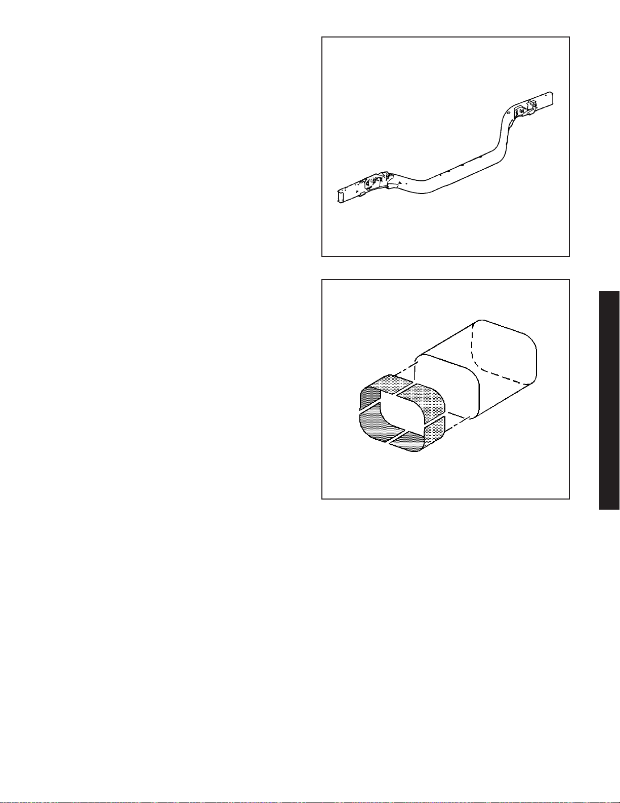
8. Remove the damaged section of frame rail within
the shaded area (1).
1654759
Installation Procedure
Caution: Refer to Collision Sectioning Caution on
page 1-1.
1. Determine the sectioning joint location within the
recommended area (1).
2-34 2006 Chevrolet Corvette Z06
Page 38
2. Cut the new frame rail end from the service frame
rail assembly.
3. Perform the sleeved butt-joint sectioning. Refer to
Sleeved Butt Joint Repair (Corvette) or Sleeved
Butt Joint Repair (Z06) on page 2-36.
4. Install the rear impact bar. Refer to Impact Bar
Replacement - Rear Bumper (Corvette) or
Impact Bar Replacement - Rear Bumper (Z06) on
page 2-14.
5. Apply the sealers and anti-corrosion materials to
the repair area. Refer to Anti-Corrosion Treatment
and Repair.
6. Paint the repair area. Refer to Basecoat/Clearcoat
Paint Systems.
7. Install all related panels and components.
8. Connect the negative battery cable. Refer to
Battery Negative Cable Disconnect/Connect
Procedure (7.0L) or Battery Negative Cable
Disconnect/Connect Procedure (6.0L).
9. Enable the SIR system. Refer to SIR Disabling
and Enabling Zones.
1654842
2006 Chevrolet Corvette Z06
857910
2006 Chevrolet Corvette Z06 2-35
Page 39
857910
Sleeved Butt Joint Repair (Z06)
Caution: Refer to Approved Equipment for
Collision Repair Caution on page 1-1.
Caution: Refer to Collision Sectioning Caution on
page 1-1.
Important: When determining the area to perform the
sectioning near a riv-nut within the recommended
areas, choose a location that centers the sleeve
through the hole. This will ensure that riv-nut fasteners
remain straight during installation.
Important: Hand tools, saw blades and abrasives
used for aluminum repairs should be dedicated
for aluminum only to prevent contamination.
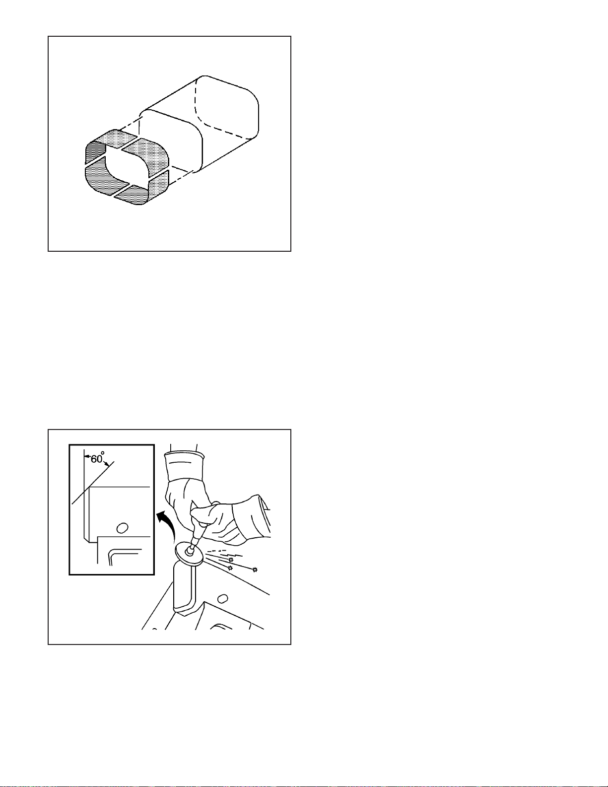
1. From the new section of frame rail, measure,
mark, and cut 50 mm (2 in) of frame rail to be
used as a sleeve (backing plate) for the
sectioning joint.
2. Cut through each side of the sleeve to create
4 individual L-shaped pieces that can be
installed in the existing frame rail.
3. Install the 4 pieces, one at a time.
4. Trim the pieces as necessary, to provide a flush
fit along the inner surface of the existing frame rail.
Important: Use a stainless steel brush to remove the
oxide layer prior to welding.
5. Clean and prepare all of the welded surfaces.
Important: Recommend wire alloy is 5356 and wire
size is 0.035. The shielding gas is 100 percent Argon.
6. Using a PULSED-MIG welder, tack weld the 4
pieces to the inner surface of the existing
frame rail.
7. Grind the existing frame rail sectioning location
and the new frame rail section to a
60-degree angle.
2-36 2006 Chevrolet Corvette Z06
1545467
Page 40
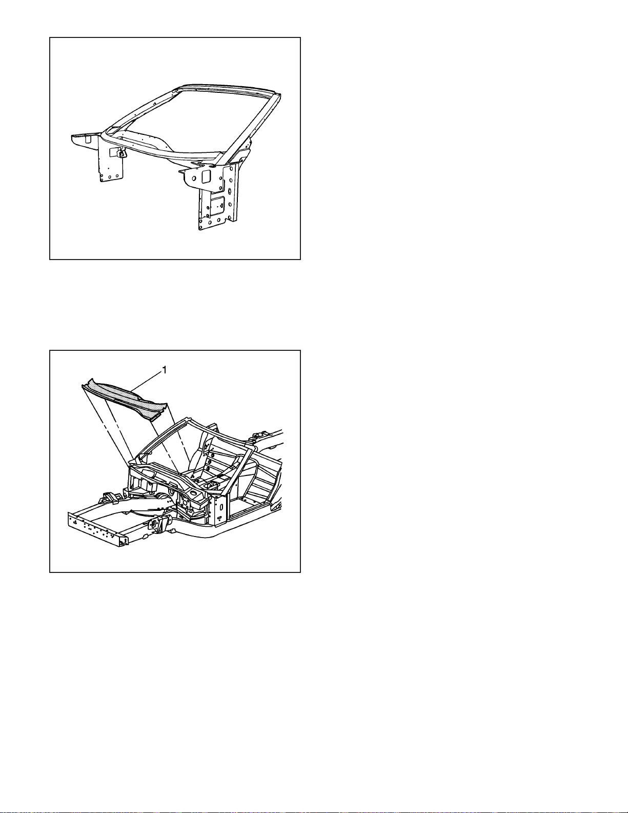
8. Install the new frame rail section to the existing
frame rail to create the butt joint while maintaining
a gap of one rail metal thickness at the sleeve
butt-joint.
9. Inspect the new frame rail section using
three-dimensional measurements.
Important: Recommend 2 weld passes (root and cap).
Recommend wire alloy is 5356 and wire size is 0.035.
The shielding gas is 100 percent Argon.
A 2 minute cooling down period is recommend for
every 2 minutes or 100 mm (4 in) of welding.
858110
10. Using a PULSED-MIG welder, complete the
welding of the sleeve joint using the 2 minute
cooling down period for every 2 minutes or
100 mm (4 in) of welding.
2006 Chevrolet Corvette Z06
858113
2006 Chevrolet Corvette Z06 2-37
Page 41
1497180
Windshield Frame Replacement
Tools Required
J 42058 Frame Adapter Clamp
Removal Procedure
The windshield frame is made of cast aluminum
components. The windshield frame is bonded and
bolted to the front hinge pillars with structural adhesive.
It is also braced to the tunnel assembly by a bolted
and bonded cross car beam.
Caution: Refer to Approved Equipment for
Collision Repair Caution on page 1-1.
Important: An attempt to repair the windshield frame
may compromise the structural integrity of the
vehicle. Complete replacement is recommended.
1. Disable the SIR system. Refer to SIR Disabling
and Enabling Zones.
2. Disconnect the negative battery cable. Refer to
Battery Negative Cable Disconnect/Connect
Procedure (7.0L) or Battery Negative Cable
Disconnect/Connect Procedure (6.0L).
3. Remove all related panels and components.
4. Drill out the close-end rivets securing the upper
plenum to the windshield frame.
5. Remove the upper plenum (1) by applying heat
and pry to detach the adhesive along the bonding
surface.
6. Separate the lower plenum from the windshield
frame by applying heat and pry to detach the
adhesive along the bonding surface.
7. Remove the bolts attaching the cross-car brace.
8. Remove the cross car brace by applying heat and
pry to detach the adhesive along the bonding
surface.
2-38 2006 Chevrolet Corvette Z06
986373
Page 42
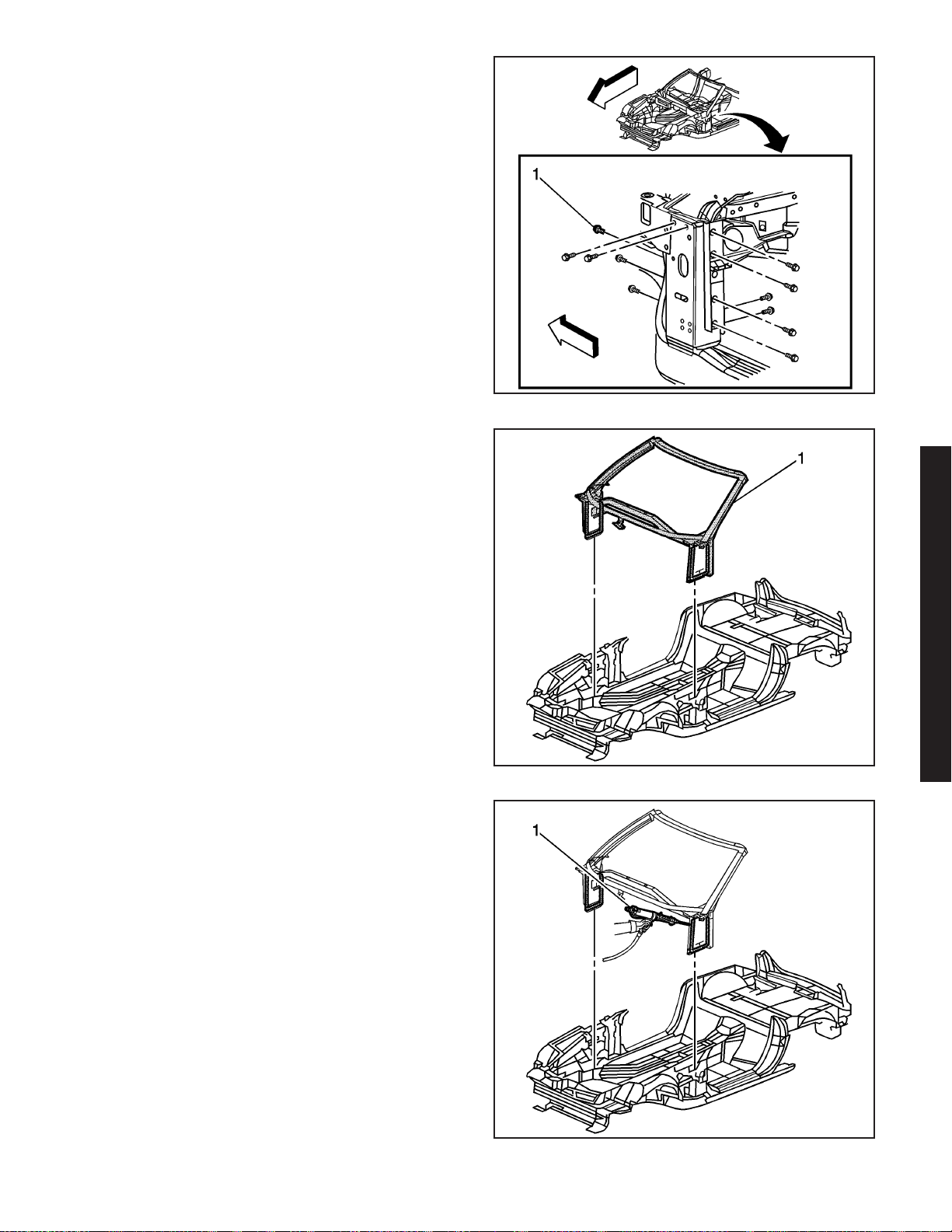
9. Remove the bolts (1) attaching the windshield
frame to the front hinge pillars.
10. Remove the windshield frame (1) by applying heat
and pry to detach the adhesive along the bonding
surface.
11. Save any and all brackets, mounting studs, and
accessories for transfer to the windshield frame.
12. Note the location of the adhesive and remove all
remaining loose adhesive.
13. Inspect the structure and frame rails for damage.
14. Repair as much of the damage as possible to
the factory specifications.
15. Use J 42058 to secure the vehicle if pulling and
straightening is required.
986434
Installation Procedure
1. Before applying adhesive, dry fit the windshield
frame for proper fit and alignment.
Important: DO NOT top coat any bonding surface.
Use primer only on bonding surfaces. Refer to
adhesive manufacturer’s recommendations.
2. Clean and prepare all bonding mating surfaces
according to adhesive manufacturer’s
recommendations.
3. Apply a consistent bead of structural adhesive (1)
10 mm (3/8 in) in diameter to the windshield frame
to mate with the bonding surfaces. Refer to
Sheet Molded Compound (SMC) Panel Bonding
on page 2-62.
2006 Chevrolet Corvette Z06
1200409
986397
2006 Chevrolet Corvette Z06 2-39
Page 43
1200409
986434
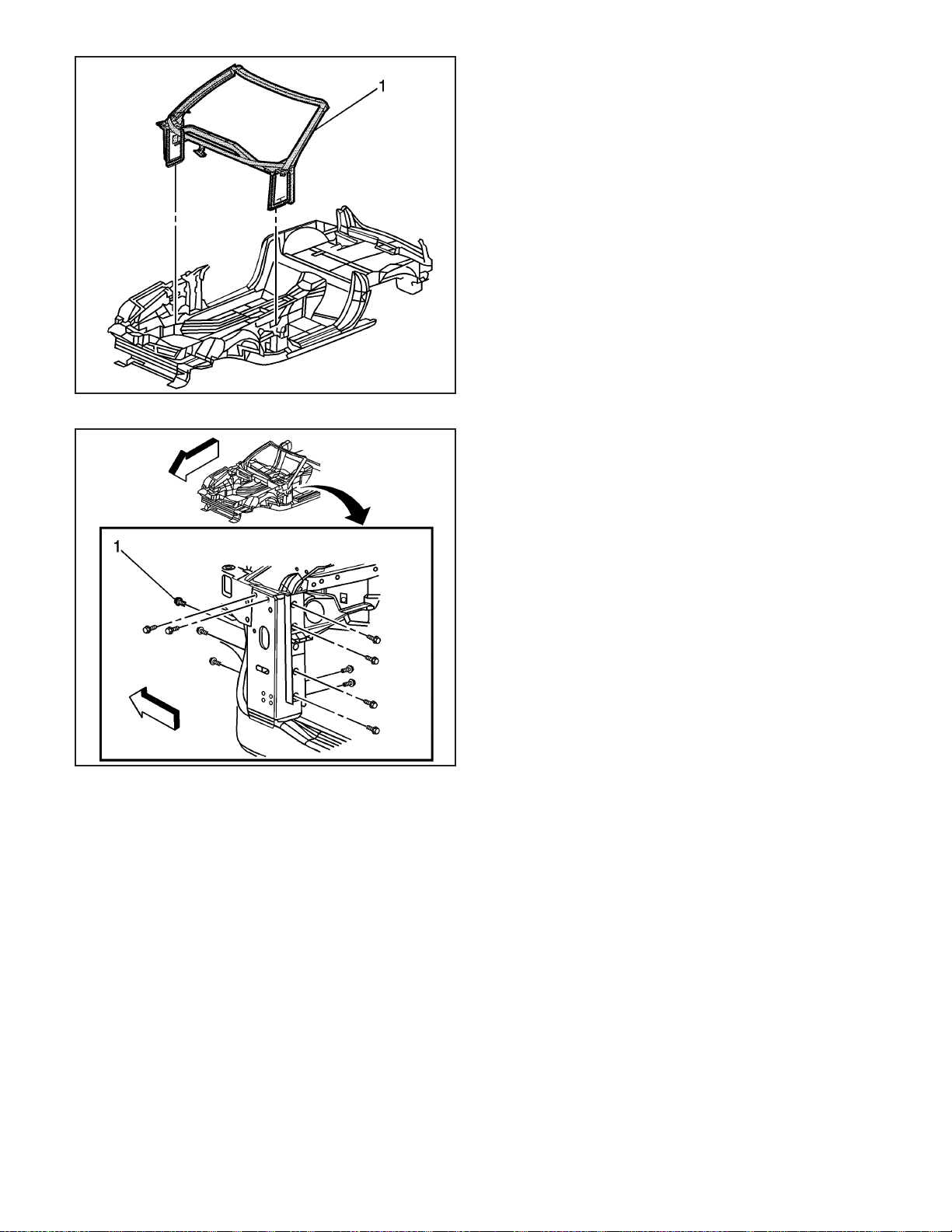
4. Install the windshield frame (1) to the vehicle.
Notice: Refer to Fastener Notice on page 1-1.
5. Install the bolts (1) that attach the windshield
frame to the front hinge pillar.
Tighten
Tighten the bolts to 25 N·m (18 lb ft).
6. Clamp or mechanically fasten the windshield
frame into place.
7. Apply structural adhesive to bond the lower
plenum to the windshield frame. Refer to
Sheet Molded Compound (SMC) Panel Bonding
on page 2-62.
8. Drill holes and use close-end rivets GM
P/N 9418420 to secure the lower plenum to the
windshield frame while adhesive cures.
9. Apply the structural adhesive to the area where
the cross-car brace bonds to the center tunnel
assembly. Refer to Sheet Molded
Compound (SMC) Panel Bonding on page 2-62.
10. Install the cross-car brace to the vehicle.
11. Install the cross-car brace bolts.
Tighten
Tighten the bolts to 25 N·m (18 lb ft).
12. Install all hardware attaching the instrument
panel (I/P) supports to the windshield frame.
2-40 2006 Chevrolet Corvette Z06
Page 44
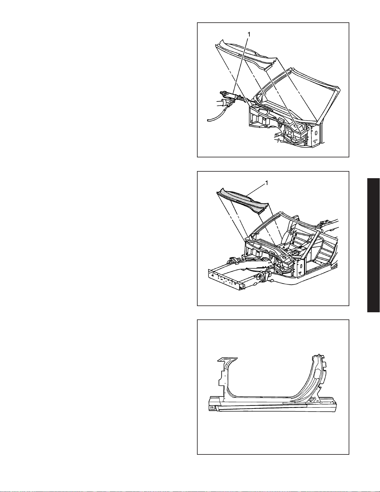
13. Apply a consistent bead of structural adhesive (1)
to the bonding surfaces to mate with the upper
plenum. Refer to Sheet Molded Compound (SMC)
Panel Bonding on page 2-62.
14. Install the upper plenum (1) to the
windshield frame.
15. Install the close-end rivets GM P/N 9418420, in
the factory locations, securing the upper plenum
to the windshield frame.
16. Remove any excess adhesive.
17. Install all related panels and components.
18. Connect the negative battery cable. Refer to
Battery Negative Cable Disconnect/Connect
Procedure (7.0L) or Battery Negative Cable
Disconnect/Connect Procedure (6.0L).
19. Enable the SIR system. Refer to SIR Disabling
and Enabling Zones.
986420
Door Opening Frame Replacement - Side
Tools Required
J 42058 Frame Adapter Clamp
Removal Procedure
Caution: Refer to Approved Equipment for
Collision Repair Caution on page 1-1.
The side door opening frame is made of sheet molded
compound (SMC), and is bonded to the side structure
and frame rail with structural adhesive.
1. Disable the SIR system. Refer to SIR Disabling
and Enabling Zones.
2. Disconnect the negative battery cable. Refer to
Battery Negative Cable Disconnect/Connect
Procedure (7.0L) or Battery Negative Cable
Disconnect/Connect Procedure (6.0L).
2006 Chevrolet Corvette Z06
986373
1497181
2006 Chevrolet Corvette Z06 2-41
Page 45
1470772
3. Remove all related panels and components.
Caution: Refer to Actions to Take When Working
with Fuel Caution on page 1-1.
4. Verify that the fuel inlet is sealed before
proceeding with repair procedure.
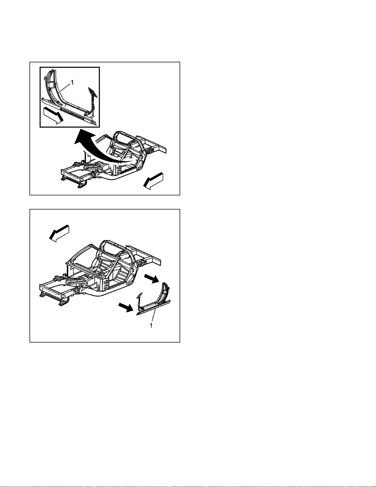
5. Remove the door frame by applying heat and pry
to detach the adhesive (1) along the bonding
surface.
1470775
6. Remove the door frame (1) from the vehicle.
7. Note the location of the adhesive and remove all
remaining loose adhesive.
8. Inspect the side structure and frame rails for
damage.
9. Repair as much of the damage as possible to the
factory specifications.
10. Use J 42058 to secure the vehicle if pulling and
straightening is required.
2-42 2006 Chevrolet Corvette Z06
Page 46
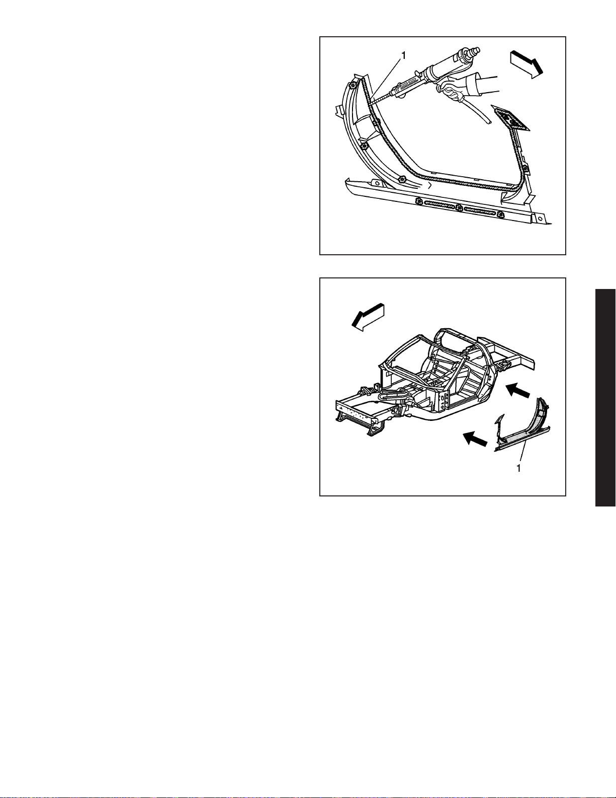
Installation Procedure
1. Before applying adhesive dry fit the door frame for
proper fit and alignment.
Important: DO NOT top coat any bonding surface.
Use primer only on bonding surfaces. Refer to
adhesive manufacturer’s recommendations.
2. Clean and prepare all bonding mating surfaces
according to adhesive manufacturer’s
recommendations.
3. Apply a consistent bead of structural adhesive
10 mm (3/8 in) in diameter to the inner surface
of the door frame to mate with the side structure
and frame rail and to all areas originally
bonded. Refer to Sheet Molded Compound (SMC)
Panel Bonding on page 2-62.
4. Position the door frame (1) to the vehicle.
5. Apply pressure to the door frame to set the
adhesive.
6. Clamp or tape the door frame in place as
necessary.
7. Remove any excess adhesive.
8. Install all related panels and components.
9. Connect the negative battery cable. Refer to
Battery Negative Cable Disconnect/Connect
Procedure (7.0L) or Battery Negative Cable
Disconnect/Connect Procedure (6.0L).
10. Enable the SIR system. Refer to SIR Disabling
and Enabling Zones.
1485945
Rail Replacement - Rear (Z06)
Tools Required
J 42058 Frame Adapter Clamp
Removal Procedure
The service rails are complete rail assemblies for the
left and the right sides, 6063–T7, hydro-formed
aluminum parts.
Caution: Refer to Approved Equipment for
Collision Repair Caution on page 1-1.
1. Disable the SIR system. Refer to SIR Disabling
and Enabling Zones.
2. Disconnect the negative battery cable. Refer to
Battery Negative Cable Disconnect/Connect
Procedure (7.0L) or Battery Negative Cable
Disconnect/Connect Procedure (6.0L).
2006 Chevrolet Corvette Z06
1470777
2006 Chevrolet Corvette Z06 2-43
Page 47
3. Remove all related panels and components.
4. Remove the rear impact bar. Refer to Impact Bar
Replacement - Rear Bumper (Corvette) or Impact
Bar Replacement - Rear Bumper (Z06) on
page 2-14.
5. Note the location and remove the sealers and
anti-corrosion materials from the repair area.
Refer to Anti-Corrosion Treatment and Repair.
6. Repair as much of the damage as possible to the
factory specifications.
7. Use J 42058 to secure the vehicle if pulling and
straightening is required.
8. Inspect the front of the dash panel, floor panels,
and all other sheet molded compound (SMC) for
cracks or areas that may need to be repaired
or resealed.
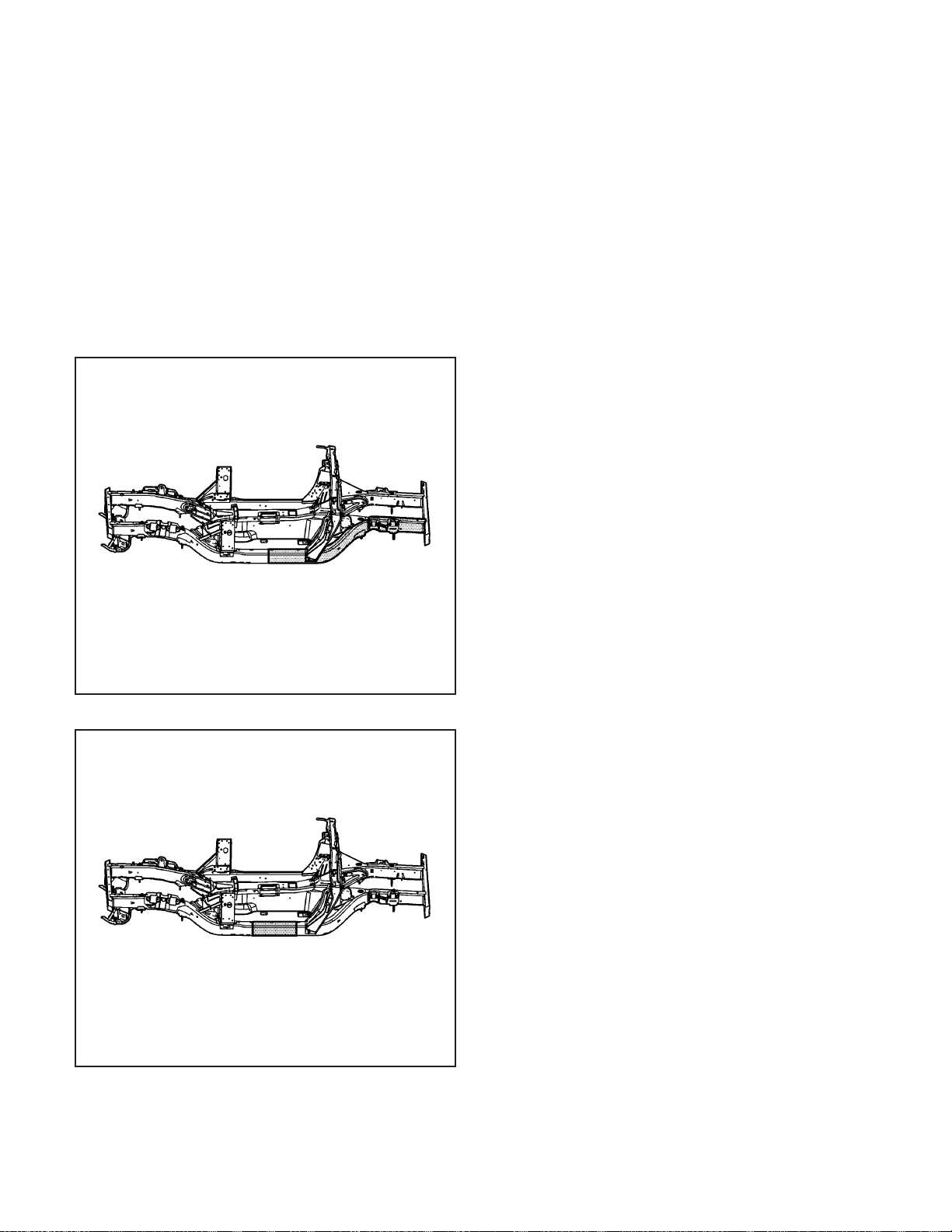
9. Remove the damaged section of frame rail.
1655991
1655985
Installation Procedure
Caution: Refer to Collision Sectioning Caution on
page 1-1.
1. Determine the sectioning joint location within the
recommended area.
2-44 2006 Chevrolet Corvette Z06
Page 48
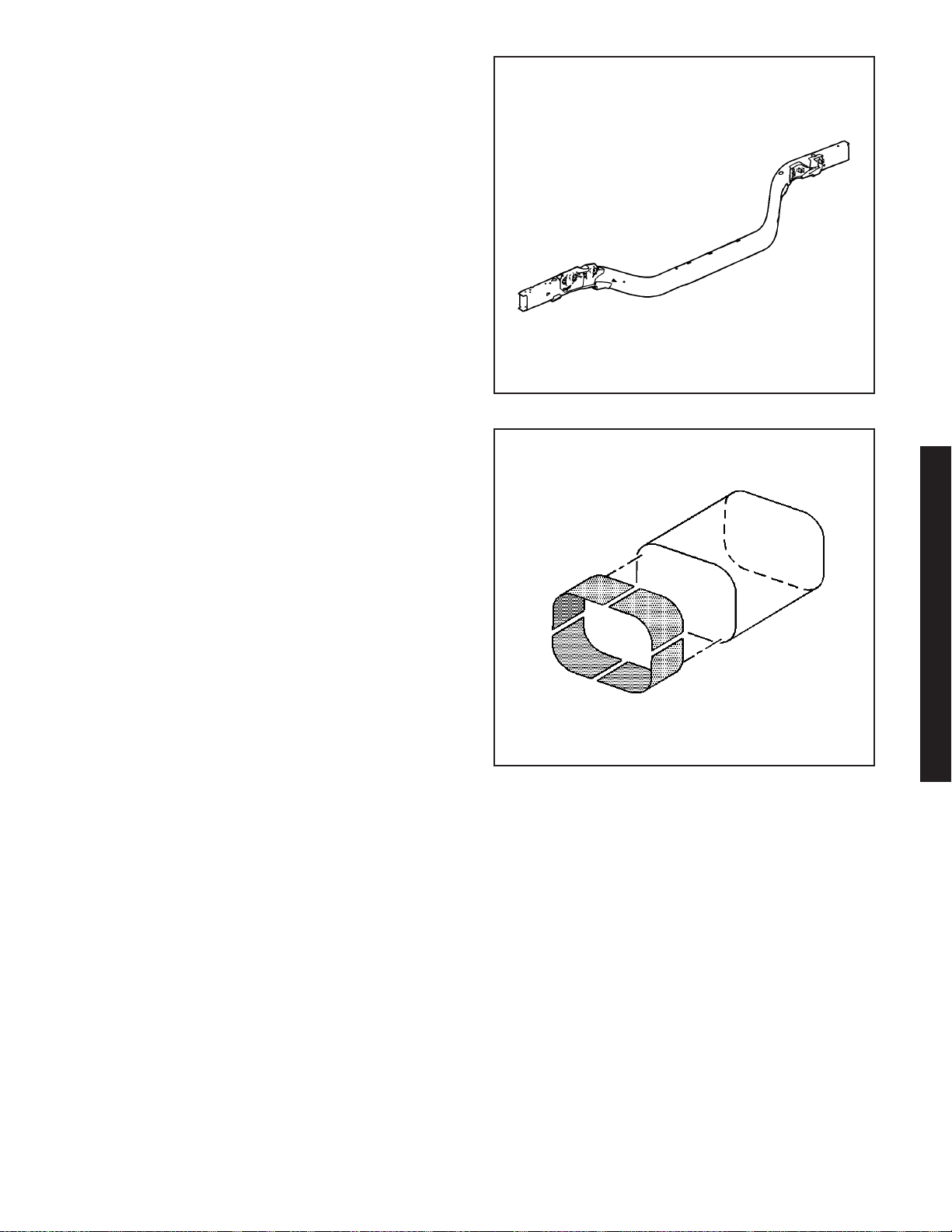
2. Cut the new frame section from the service frame
rail assembly.
3. Perform the sleeved butt-joint sectioning. Refer to
Sleeved Butt Joint Repair (Corvette) or Sleeved
Butt Joint Repair (Z06) on page 2-36.
4. Install the rear impact bar. Refer to Impact Bar
Replacement - Rear Bumper (Corvette) or
Impact Bar Replacement - Rear Bumper (Z06) on
page 2-14.
5. Apply the sealers and anti-corrosion materials to
the repair area. Refer to Anti-Corrosion Treatment
and Repair.
6. Paint the repair area. Refer to Basecoat/Clearcoat
Paint Systems.
7. Install the related panels and components.
8. Connect the negative battery cable. Refer to
Battery Negative Cable Disconnect/Connect
Procedure (7.0L) or Battery Negative Cable
Disconnect/Connect Procedure (6.0L).
9. Enable the SIR system. Refer to SIR Disabling
and Enabling Zones.
1654842
2006 Chevrolet Corvette Z06
857910
2006 Chevrolet Corvette Z06 2-45
Page 49
1662707
1662267
Rail Replacement - Rear Section (Z06)
Tools Required
J 42058 Frame Adapter Clamp
Removal Procedure
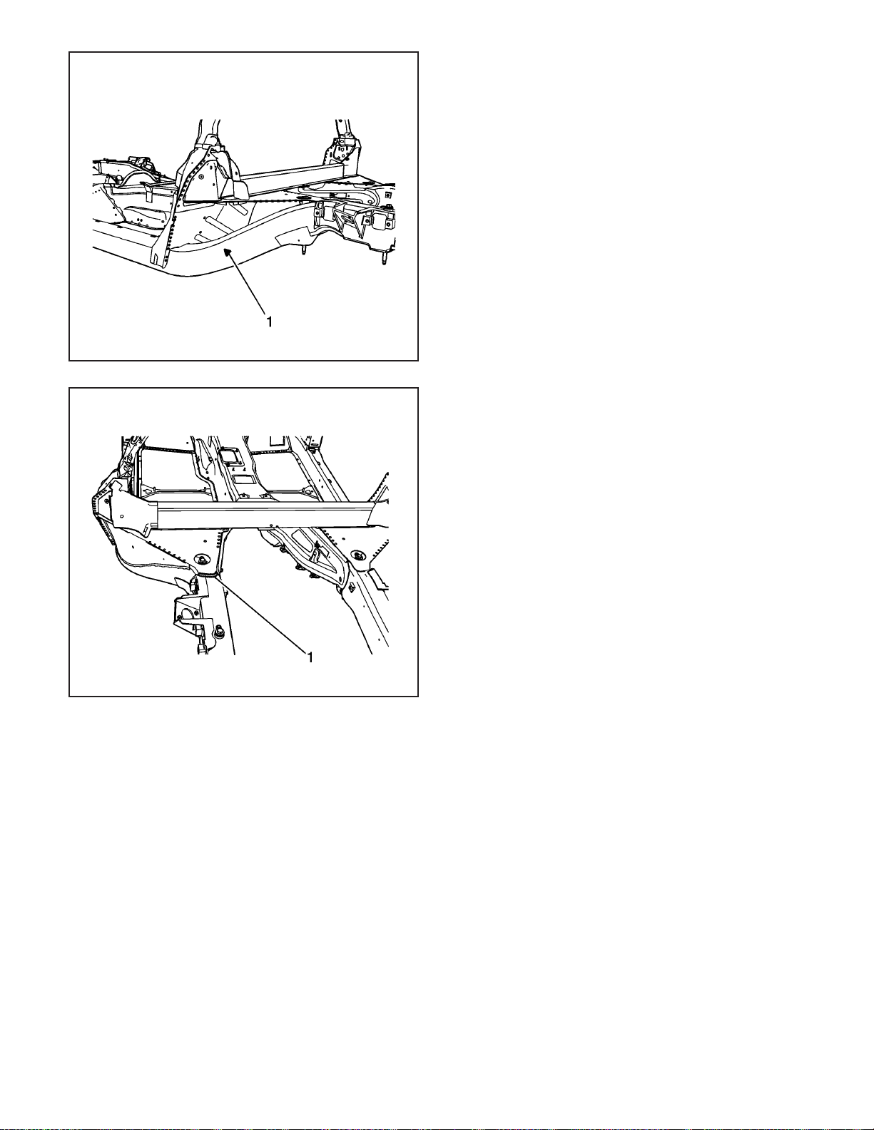
The service rails are complete rail assemblies for the
left and the right sides, 6063–T7, hydro-formed
aluminum parts, which correlate directly with the die
mark (1) located on the rear frame rails
Caution: Refer to Approved Equipment for
Collision Repair Caution on page 1-1.
1. Disable the SIR system. Refer to SIR Disabling
and Enabling Zones.
2. Disconnect the negative battery cable. Refer to
Battery Negative Cable Disconnect/Connect
Procedure (7.0L) or Battery Negative Cable
Disconnect/Connect Procedure (6.0L).
3. Remove all related panels and components.
4. Remove the front impact bar. Refer to Impact Bar
Replacement - Front Bumper (Corvette) or Impact
Bar Replacement - Front Bumper (Z06) on
page 2-5.
5. Note the location and remove the sealers and
anti-corrosion materials from the repair area, as
necessary. Refer to Anti-Corrosion Treatment and
Repair.
6. Repair as much of the damage as possible to the
factory specifications.
7. Use J 42058 to secure the vehicle if pulling and
straightening is required.
8. Inspect the front of the dash panel, floor panels,
and all other sheet molded compound (SMC) and
carbon fiber for cracks or areas that may need
to be repaired or resealed.
Important: Hand tools, saw blades and abrasives
used for aluminum repairs should be dedicated
for aluminum only to prevent contamination.
9. Locate and remove all factory welds attaching the
upper extension panel (1) to the structure. Note
the location of the welds for installation of the
upper extension panel.
2-46 2006 Chevrolet Corvette Z06
Page 50
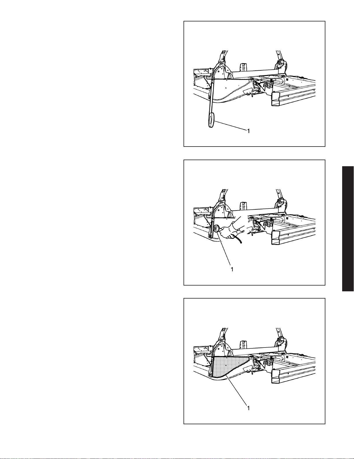
Caution: Refer to Sound Deadener Foam in the
Lock Striker Pillars Caution on page 1-1.
10. Apply 25 mm (1 in) tape to the extension panel of
the outer lock pillar.
11. Using a die grinder (1), cut along the edge of the
tape line to create a weld flange, which will be
used for installing the new extension panel for the
outer lock pillar.
1662022
12. Locate and remove all factory welds (1) attaching
the extension panel to the structure. Note the
location of the welds for installation of the
new extension panel.
13. Using a drill with a 6 mm (1/4 in) bit, locate and
remove all self-piercing rivets (SPR). Note the
number and location of the SPRs for installation of
the extension panel.
14. Remove the extension panel.
2006 Chevrolet Corvette Z06
1662140
1662156
2006 Chevrolet Corvette Z06 2-47
Page 51
1662707
Caution: Refer to Collision Sectioning Caution on
page 1-1.
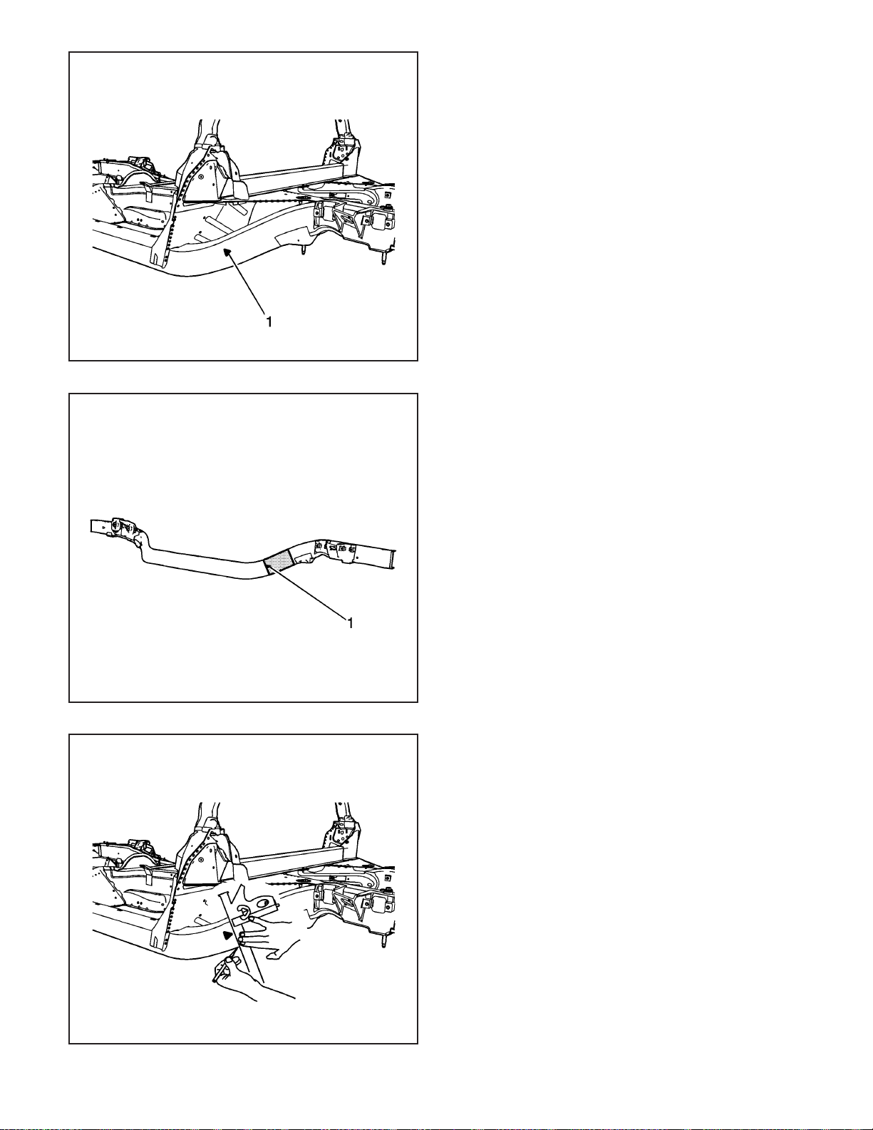
15. Locate the die-mark (1) on the damaged
frame rail.
16. Determine the sectioning joint location within the
recommended area.
2-48 2006 Chevrolet Corvette Z06
1576968
17. At the determined sectioning joint align a sliding
square or similar tool square to surface to the
vertical walls of the frame rail.
1662728
Page 52
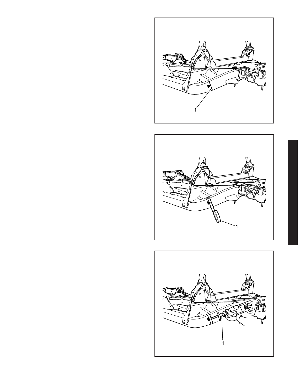
18. Scribe a line (1) to both sides of the frame rail.
19. Apply masking tape (1) to the scribe line
completely around the frame rail.
1664011
20. Cut the frame rail at the rear edge of the tape line
using a reciprocating saw (1) or equivalent tool.
2006 Chevrolet Corvette Z06
1662844
1663138
2006 Chevrolet Corvette Z06 2-49
Page 53
1663988
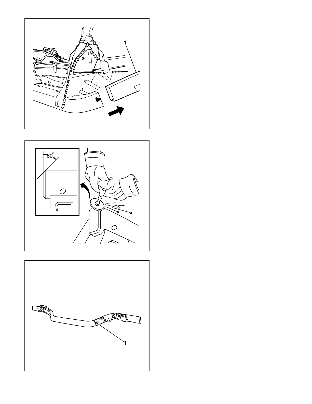
21. Remove the damaged frame rail section (1).
Installation Procedure
1. Grind the existing frame rail sectioning location to
a 60 degree angle.
2-50 2006 Chevrolet Corvette Z06
1545467
Caution: Refer to Collision Sectioning Caution on
page 1-1.
2. Locate the die-mark (1) on the service frame rail.
3. Determine the sectioning joint location within
the recommended area.
4. Cut the new frame section from the service frame
rail assembly.
1576968
Page 54
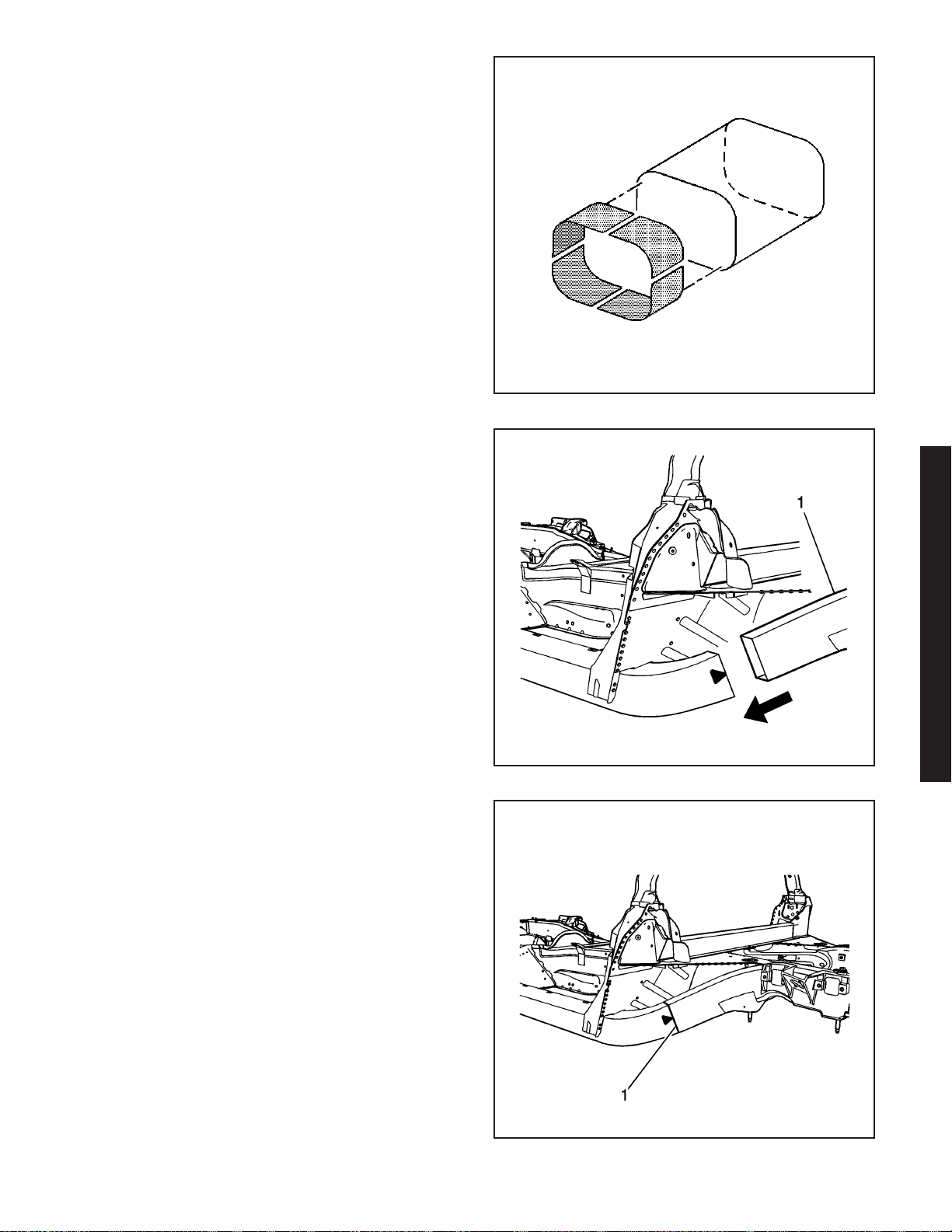
5. Perform the sleeved butt-joint sectioning. Refer to
Sleeved Butt Joint Repair (Corvette) or Sleeved
Butt Joint Repair (Z06) on page 2-36.
Important: Use a stainless steel brush to remove the
oxide layer prior to welding.
6. Clean and prepare all of the welded mating
surfaces.
7. Position the service frame section (1) to the
existing frame.
857910
8. Maintain a gap of one frame rail metal thickness
at the sectioning joint (1) and clamp in place.
9. Inspect the frame measurements
three-dimensional to ensure proper position of the
service frame section.
2006 Chevrolet Corvette Z06
1663989
1664011
2006 Chevrolet Corvette Z06 2-51
Page 55
1664082
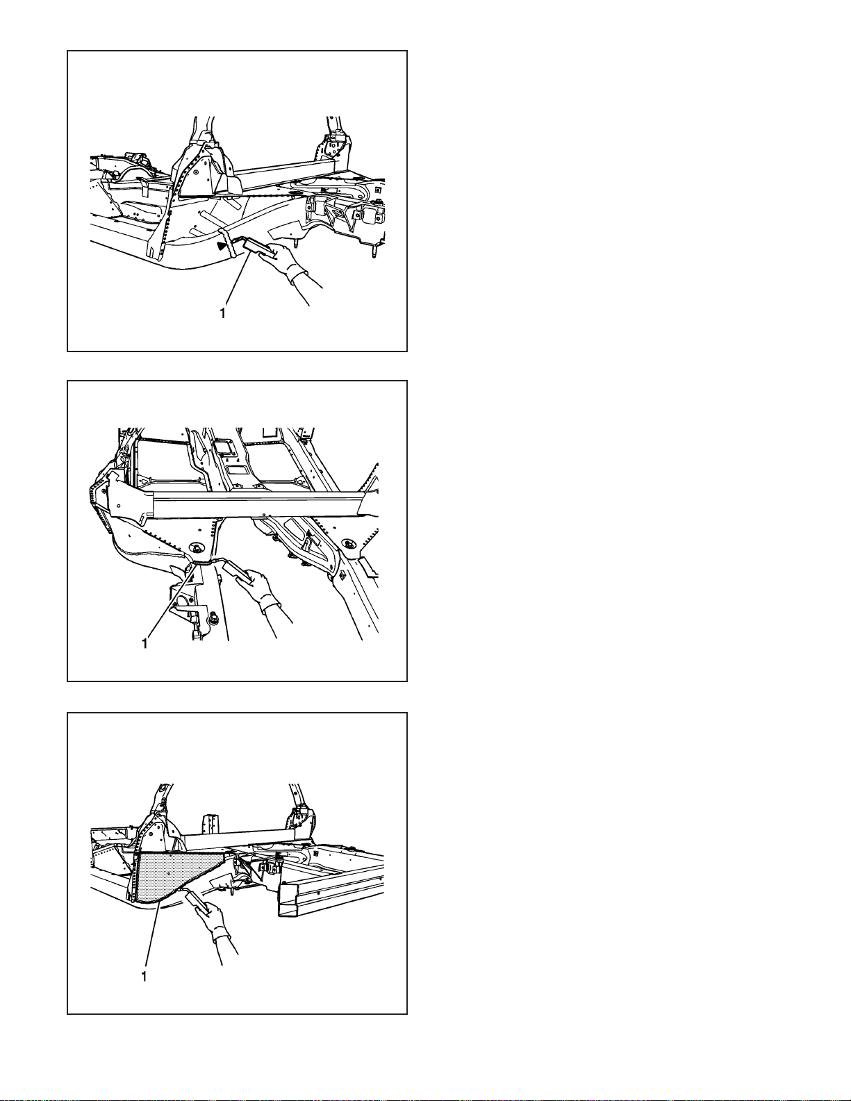
Important: Recommend two weld passes (root
and cap).
Recommend wire alloy is 5356 and wire size is 0.035.
The shielding gas is 100% Argon.
A two minute cooling down period is recommend for
every 2 minutes or 100–mm (4–in) of welding.
10. Using a PULSED-MIG (P-MIG) welder, weld
50–mm (2–in) stitch welds to the top and
bottom of the sleeve joint.
11. Using a P-MIG welder, weld (1) 50–mm (2–in)
welds to the inner and outer vertical walls of the
sleeve joint.
12. Inspect the frame measurements
three-dimensional to ensure proper position of the
service frame section.
13. Using a P-MIG welder, complete the welding of
the sleeve joint using the two minute cooling
down period for every 2 minutes or 100–mm
(4–in) of welding.
14. Using a P-MIG welder, stitch weld (1) the upper
extension panel (1) to the structure duplicating the
factory welds.
2-52 2006 Chevrolet Corvette Z06
1662269
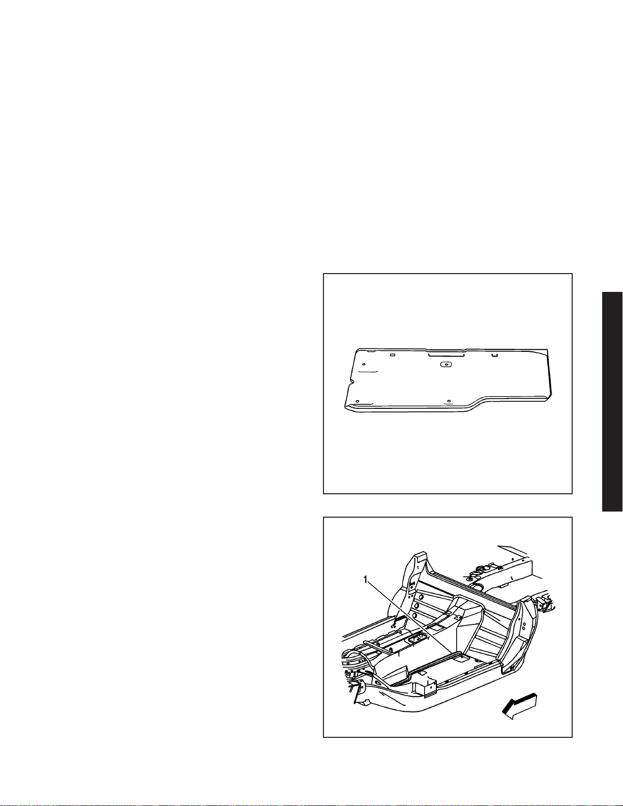
15. Install the new the extension panel. Trim to fit the
extension panel overlapping the 25 mm (1 in)
flange created from the original extension.
Important: A two minute cooling down period is
recommend for every 2 minutes or 100–mm (4–in) of
welding.
16. Using a P-MIG welder, stitch weld (1) the
extension panel to the srtucture duplicating
the factory welds.
17. Using a P-MIG welder, stitch weld the extension
panel to the flange created form the original
extension.
Important: Replace the SPRs with a structural
monobolt rivet, GM Part Number 19120691.
The structural monobolt rivet requires a special nose
tip, BO48073.
18. Drill 6 mm (1/4 in) holes in the service part as
necessary in the locations noted on the
original panel.
1662158
Page 56
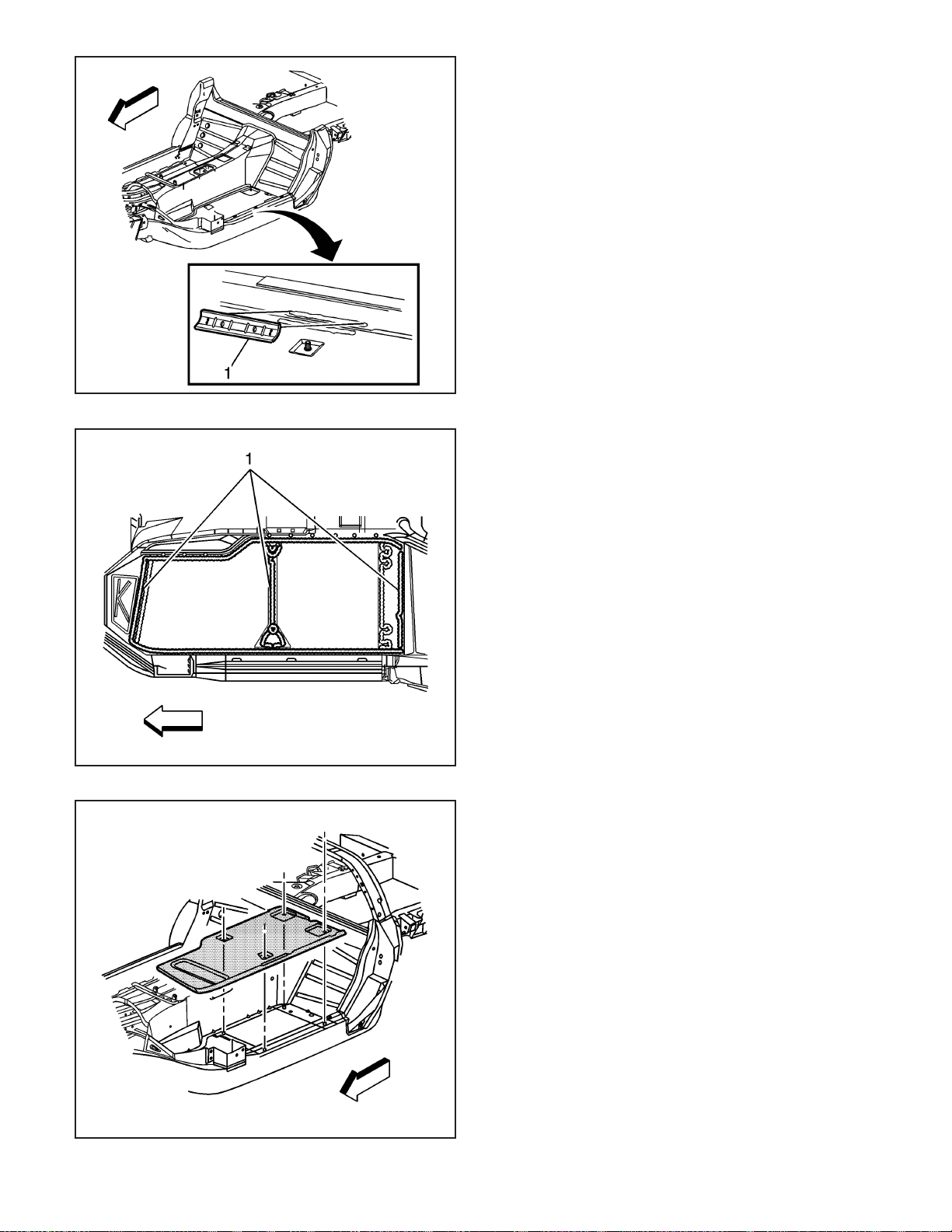
19. Using a rivet gun, attach the extension panel with
structural monobolt rivets to the structure
duplicating the number of factory SPRs.
20. Install the front impact bar. Refer to Impact Bar
Replacement - Front Bumper (Corvette) or
Impact Bar Replacement - Front Bumper (Z06) on
page 2-5.
21. Apply the sealers and anti-corrosion materials to
the repair area, as necessary. Refer to
Anti-Corrosion Treatment and Repair.
22. Paint the repair area. Refer to Basecoat/Clearcoat
Paint Systems.
23. Install all related panels and components.
24. Connect the negative battery cable. Refer to
Battery Negative Cable Disconnect/Connect
Procedure (7.0L) or Battery Negative Cable
Disconnect/Connect Procedure (6.0L).
25. Enable the SIR system. Refer to SIR Disabling
and Enabling Zones.
Floor Panel Replacement (Z06)
Tools Required
J 42058 Frame Adapter Clamp
Removal Procedure
Caution: Refer to Approved Equipment for
Collision Repair Caution on page 1-1.
The floor panel is made of carbon fiber, and is bonded
to the structure with structural adhesive.
1. Disable the SIR system. Refer to SIR Disabling
and Enabling Zones.
2. Disconnect the negative battery cable. Refer to
Battery Negative Cable Disconnect/Connect
Procedure (7.0L) or Battery Negative Cable
Disconnect/Connect Procedure (6.0L).
3. Remove all related panels and components.
4. Remove or reposition electrical components and
wiring harness as necessary to avoid damage.
5. Remove wiring harness clips for transfer to new
floor panel.
6. Remove the inner reinforcement (1) bonded to the
floor panel and the tunnel area.
2006 Chevrolet Corvette Z06
1497179
966577
2006 Chevrolet Corvette Z06 2-53
Page 57
966581
7. Remove the outer reinforcement (1) bonded to the
floor panel and the frame rail.
8. Using a reciprocating saw or equivalent tool cut a
large section of the floor out to gain access to the
bond joint.
9. Remove the remaining floor by applying heat and
prying to detach adhesive along the bonding
surface (1).
2-54 2006 Chevrolet Corvette Z06
966585
10. Remove the floor panel from the vehicle.
11. Save any and all brackets, mounting studs, and
accessories for transfer to the new floor.
12. Note the location and remove all remaining loose
adhesive.
13. Inspect the structure and frame rails for damage.
14. Repair as much of the damage as possible to
the factory specifications.
15. Use J 42058 to secure the vehicle if pulling and
straightening is required.
966590
Page 58
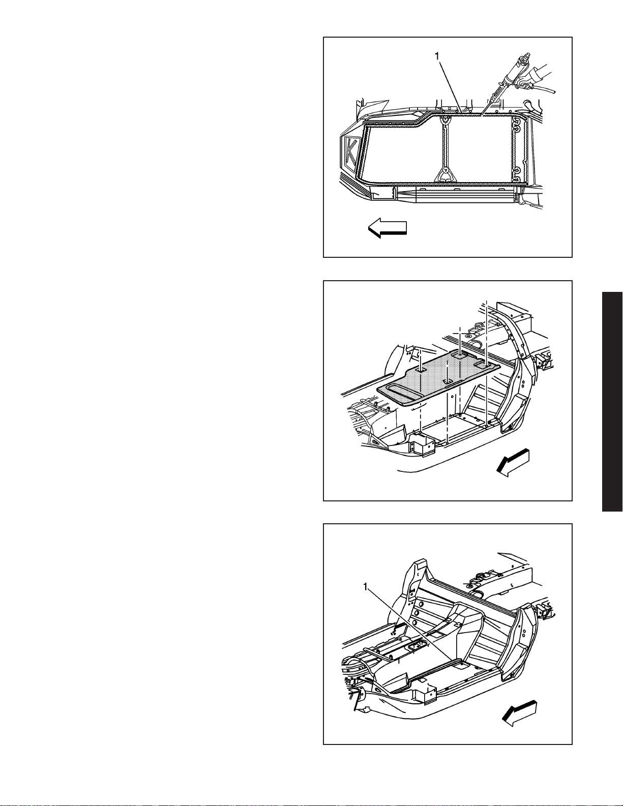
Installation Procedure
1. Before applying adhesive dry fit the floor panel for
proper fit and alignment.
Important: DO NOT top coat any bonding surface.
Use primer only on bonding surfaces. Refer to
adhesive manufacturer’s recommendations.
2. Clean and prepare all bonding mating surfaces
according to adhesive manufacturer’s
recommendations.
Important: Keep adhesive away from seat studs to
minimize squeeze out.
3. Apply a consistent bead of structural adhesive (1)
10 mm (3/8 in) in diameter to the floor structure
and frame rail to mate with the bonding surface of
the floor. Refer to Sheet Molded Compound (SMC)
Panel Bonding on page 2-62.
4. Install the floor panel to the vehicle.
5. Apply pressure to the floor panel to set the
adhesive.
6. Install the seat mounting nuts to set the adhesive
at the cross brace.
966595
7. Apply structural adhesive (1) to the inner floor
panel reinforcement. Refer to Sheet Molded
Compound (SMC) Panel Bonding on page 2-62.
8. Install the inner floor panel reinforcement to the
tunnel.
9. Apply pressure to the reinforcement to set the
adhesive.
2006 Chevrolet Corvette Z06
966590
966577
2006 Chevrolet Corvette Z06 2-55
Page 59
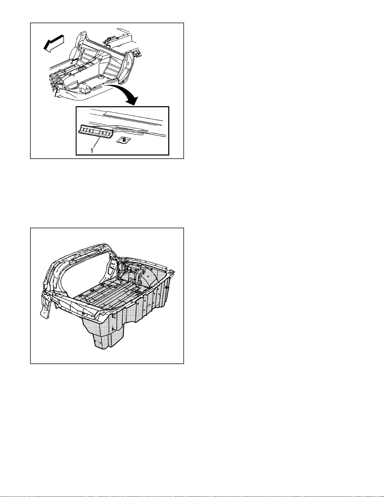
966581
10. Apply structural adhesive (1) to the outer floor
panel reinforcement. Refer to Sheet Molded
Compound (SMC) Panel Bonding on page 2-62.
11. Install the outer floor panel reinforcement to the
frame rail.
12. Apply pressure to the reinforcement to set the
adhesive.
13. Apply structural adhesive to wiring harness clips,
and install at the etched indicators on the floor
panel by pressing firmly into place. Refer to Sheet
Molded Compound (SMC) Panel Bonding on
page 2-62.
14. Smooth adhesive around perimeter of floor panel
from underside of vehicle to form a consistent,
leak-proof seal.
15. Clamp or mechanically fasten the front end panel
into place as necessary.
16. Remove any excess adhesive.
17. Install all related panels and components.
18. Remove the seat mounting nuts.
19. Connect the negative battery cable. Refer to
Battery Negative Cable Disconnect/Connect
Procedure (7.0L) or Battery Negative Cable
Disconnect/Connect Procedure (6.0L).
20. Enable the SIR system. Refer to SIR Disabling
and Enabling Zones.
1459993
Compartment Panel Replacement - Rear
(Corvette)
Tools Required
J 42058 Frame Adapter Clamp
Removal Procedure
The rear compartment panel is made of sheet molded
compound (SMC), and is bonded to the rear
structure and frame rails with structural adhesive.
Caution: Refer to Approved Equipment for
Collision Repair Caution on page 1-1.
1. Disable the SIR system. Refer to SIR Disabling
and Enabling Zones.
2. Disconnect the negative battery cable. Refer to
Battery Negative Cable Disconnect/Connect
Procedure (7.0L) or Battery Negative Cable
Disconnect/Connect Procedure (6.0L).
3. Remove all related panels and components.
Caution: Refer to Actions to Take When Working
with Fuel Caution on page 1-1.
4. Verify that the fuel inlet is sealed before
proceeding with the repair procedure.
5. Remove the rear compartment frame panel. Refer
to Compartment Panel Frame Replacement -
Rear (Corvette) on page 2-59.
2-56 2006 Chevrolet Corvette Z06
Page 60
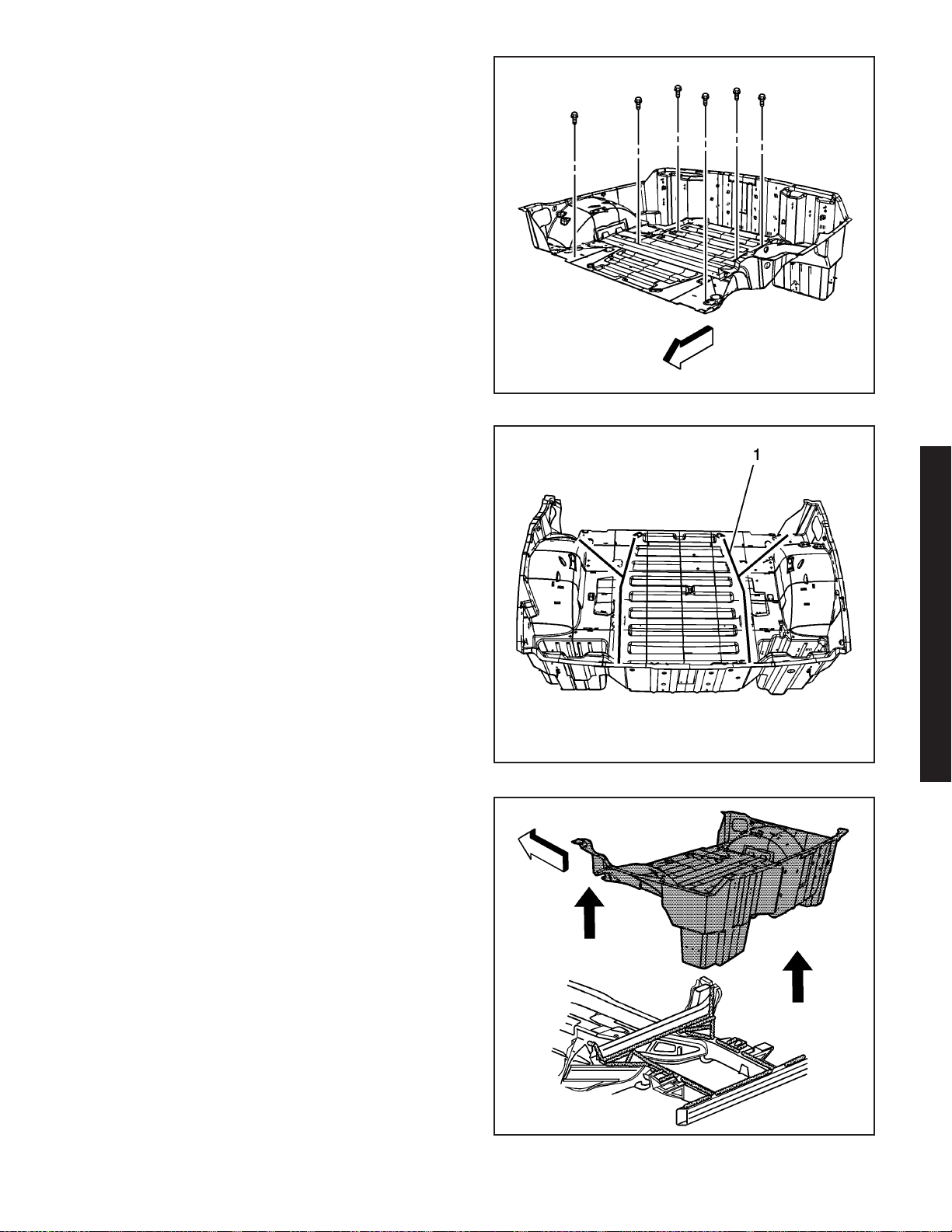
6. Remove the screws attaching the rear
compartment panel to the frame rails.
Important: The front edge of the rear compartment
panel is also bonded across the seatback area and
along the top of the rear impact bar.
7. Remove the rear compartment panel by applying
heat to the inside of the rear compartment along
the bond lines (1) indicated on the floor.
8. Pry to detach the adhesive along the bonding
surface.
9. The front edge of the rear compartment panel is
also bonded across the seatback area and along
the top of the rear impact bar. Apply heat and
pry to detach the adhesive along the bonding
surface.
1459995
10. Remove the rear compartment panel.
11. Save all brackets, mounting studs, and
accessories for transfer to the new rear
compartment panel.
12. Note the location of the adhesive and remove all
remaining loose adhesive.
13. Inspect the rear structure and the frame rails for
damage.
14. Repair as much of the damage as possible to the
factory specifications.
15. Use J 42058 to secure the vehicle if pulling and
straightening is required.
2006 Chevrolet Corvette Z06
1459998
1459999
2006 Chevrolet Corvette Z06 2-57
Page 61
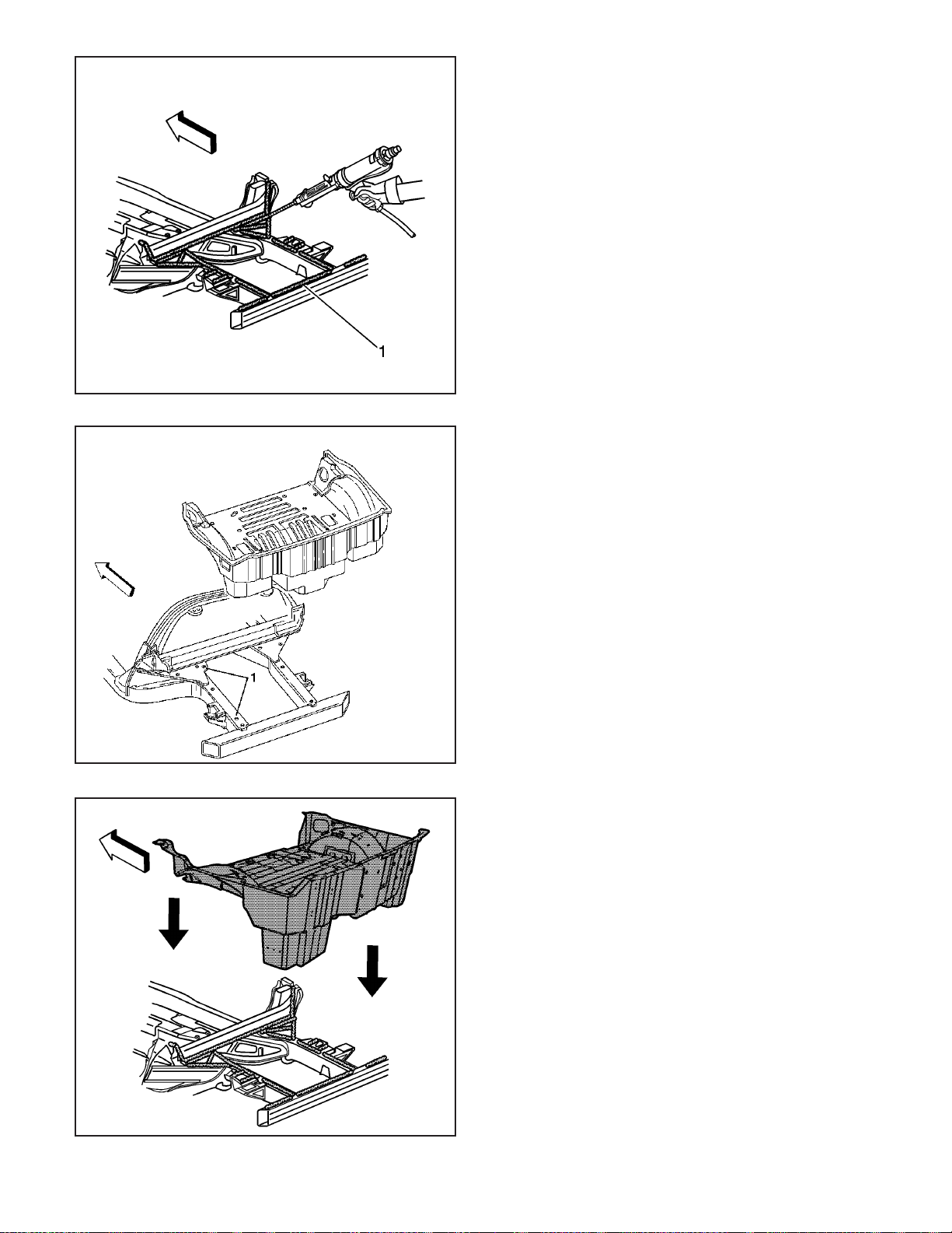
948030
Installation Procedure
1. Before applying the adhesive, dry fit the rear
compartment panel for proper fit and alignment.
Important: Do NOT top coat any bonding surface.
Use primer only on bonding surfaces. Refer to
adhesive manufacturer’s recommendations.
2. Clean and prepare all bonding mating surfaces
according to the adhesive manufacturer’s
recommendations.
3. Apply a consistent bead of structural adhesive (1)
12 mm (1/2 in) in diameter to the following
locations. Refer to Sheet Molded
Compound (SMC) Panel Bonding on page 2-62.
• The top of the frame rails
• The backside of the lock pillars
• Over the fuel filler neck
• To all original bonding surfaces
Important: The rear compartment panel is positioned
to the drive side frame rail using 2 dimples formed in
the bottom surface of the rear compartment panel.
4. Position the rear compartment panel to the
2 holes (1) in the frame rail.
2-58 2006 Chevrolet Corvette Z06
181202
5. Install the rear compartment panel to the vehicle.
6. Apply pressure to the rear compartment panel to
set the adhesive.
1460000
Page 62
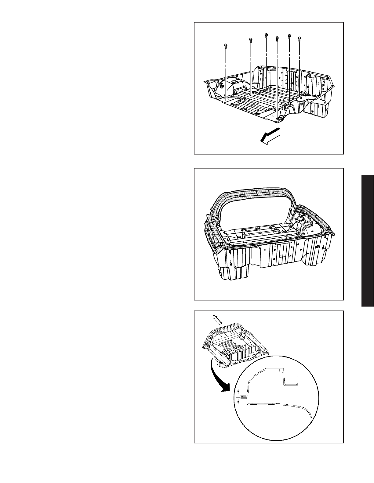
7. Install the screws attaching the rear compartment
panel to the frame rails.
8. Clamp or mechanically fasten the rear
compartment panel in place as necessary.
9. Remove any excess adhesive.
10. Install the rear compartment frame panels. Refer
to Compartment Panel Frame Replacement -
Rear (Corvette) on page 2-59.
11. Install all related panels and components.
12. Connect the negative battery cable. Refer to
Battery Negative Cable Disconnect/Connect
Procedure (7.0L) or Battery Negative Cable
Disconnect/Connect Procedure (6.0L).
13. Enable the SIR system. Refer to SIR Disabling
and Enabling Zones.
Compartment Panel Frame Replacement Rear (Corvette)
Tools Required
J 42058 Frame Adapter Clamp
1459995
Removal Procedure
The rear compartment frame is made of sheet molded
compound (SMC), and is bonded to the rear structure
with structural adhesive.
Caution: Refer to Approved Equipment for
Collision Repair Caution on page 1-1.
1. Disable the SIR system. Refer to SIR Disabling
and Enabling Zones.
2. Disconnect the negative battery cable. Refer to
Battery Negative Cable Disconnect/Connect
Procedure (7.0L) or Battery Negative Cable
Disconnect/Connect Procedure (6.0L).
3. Remove all related panels and components.
4. Remove the rear compartment frame by applying
heat, and pry to detach the adhesive along the
bonding surface.
2006 Chevrolet Corvette Z06
1459658
181214
2006 Chevrolet Corvette Z06 2-59
Page 63
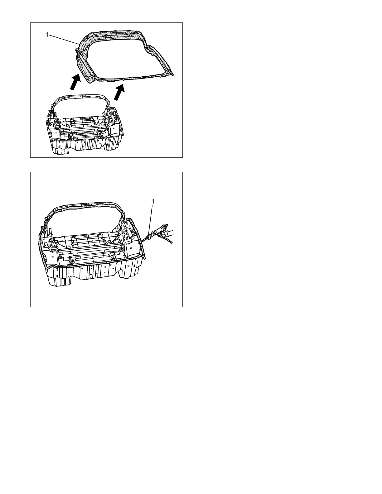
1459669
5. Remove the rear compartment frame (1).
6. Note the location of the adhesive and remove all
remaining loose adhesive.
7. Inspect the rear structure and frame rails for
damage.
8. Repair as much of the damage as possible to the
factory specifications.
9. Use J 42058 to secure the vehicle if pulling and
straightening is required.
Installation Procedure
Important: Shims may be necessary to achieve
proper panel alignment.
1. Before applying the adhesive, dry fit the rear
compartment frame for proper fit and alignment.
2. Clean and prepare all bonding mating surfaces
according to the adhesive manufacturer’s
recommendations.
3. Apply a consistent bead of structural adhesive (1)
10 mm (3/8 in) in diameter to the rear structure in
order to mate with the rear compartment frame.
Refer to Sheet Molded Compound (SMC)
Panel Bonding on page 2-62.
2-60 2006 Chevrolet Corvette Z06
1459929
Page 64
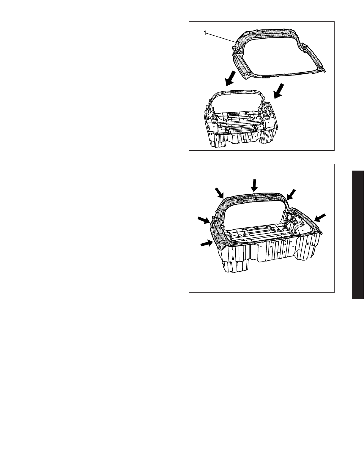
4. Install the rear compartment frame (1).
5. Apply pressure to the rear compartment frame to
set the adhesive.
6. Clamp or mechanically fasten the rear
compartment frame into place.
7. Remove any excess adhesive.
8. Install all related panels and components.
9. Connect the negative battery cable. Refer to
Battery Negative Cable Disconnect/Connect
Procedure (7.0L) or Battery Negative Cable
Disconnect/Connect Procedure (6.0L).
10. Enable the SIR system. Refer to SIR Disabling
and Enabling Zones.
1459670
1459665
2006 Chevrolet Corvette Z06 2-61
2006 Chevrolet Corvette Z06
Page 65
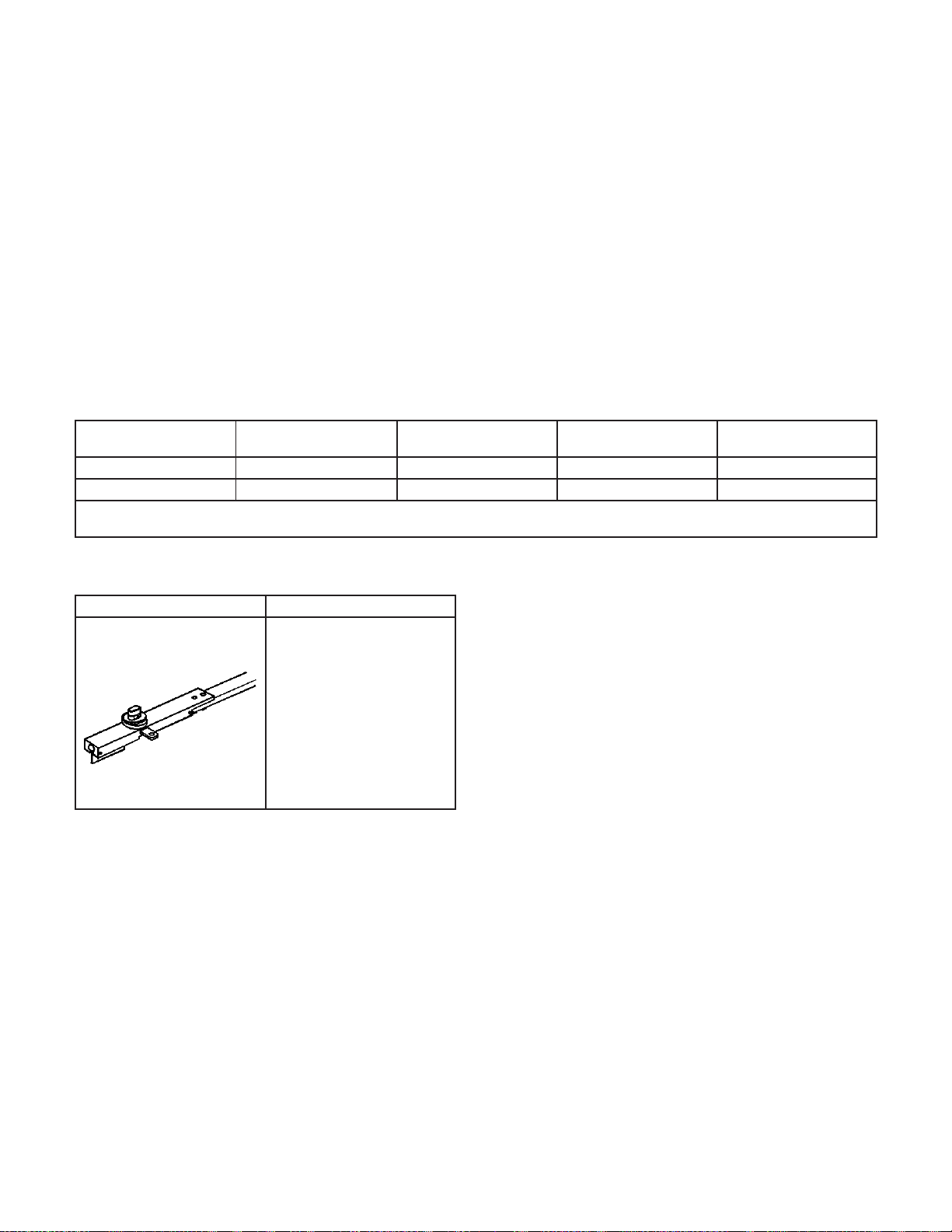
Description and Operation
Sheet Molded Compound (SMC) Panel
Bonding
Important:
• Prepare the surfaces to be bonded according to
adhesive manufacturer’s recommendations.
This is intended to provide general guidelines for
sheet molded compound (SMC) and carbon fiber
adhesive bonding of full panel replacement in regards
to collision repair procedures.
Sectioning, partial panel of full panels, is not supported
by General Motors unless specifically documented
in a Service Bulletin or Manual.
Many adhesive manufacturers have different
preparation methods. Do not intermix adhesive
manufacturers systems. Mixing materials
from different manufacturers can produce
unsatisfactory results.
• DO NOT top coat any adhesive bonding mating
surface. Use primer only on bonding surfaces.
Refer to adhesive manufacturer’s
recommendations for priming applications.
Adhesives currently meeting the performance
requirements include General Motors materials and
products manufactured by Ashland and Lord Fusor. At
this time, ONLY the adhesive products listed below
meet this guideline:
Sheet Molded Compound (SMC) Panel Bonding
GM Goodwrench
89020330 8902332 7770B 127 EZ Medium Set
N/A N/A 7779B N/A Fast Set
Canadian applications may use U.S. part numbers. Refer to your GM Dealer Parts Department for the correct part number
applications.
®
GMSPO of Canada
Ashland Pliogrip
Structure Adhesive
Lord Fusor Structural
Adhesive Product Type
Special Tools and Equipment
Illustration Tool Number/ Description
J 42058 Frame
Adapter Clamp
803311
2-62 2006 Chevrolet Corvette Z06
 Loading...