

Page 1

REPAIR & TUNE-UP GUIDE
CORVETTE
1963 to 1983
All U.S. and Canadian 305 « 327 • 350 • 396 * 427 • 454 models;
including fuel injection
President, Chilton Enterprises David S. Loewith
Senior Vice President Ronald A. Hoxter
Publisher and Editor-in-Chief Kerry A. Freeman, S.A.E.
Managing Editors Peter M. Conti, Jr. a W. Calvin Settle, Jr., S.A.E.
Assistant Managing Editor Nick D'Andrea
Senior Editors Debra Gaffney a Ken Grabowski, A.S.E., S.A.E. Michael L.
Grady a Richard J. Rivele, S.A.E. Richard T. Smith n Jim Taylor Ron Webb
Director of Manufacturing Mike D'lmperio
Editor Tony Molla, S.A.E.
1BOOK
^COMPANY
ONE OF THE DIVERSIFIED PUBLISHING COMPANIES,
A PART OF CAPITAL CITIES/ABC, INC.
Page 2

SAFETY NOTICE
Proper service and repair procedures are vital to the safe, reliable operation of all motor vehicles, as well as the personal safety of those performing repairs. This book outlines procedures
for servicing and repairing vehicles using safe, effective methods. The procedures contain many
NOTES, CAUTIONS and WARNINGS which should be followed along with standard safety procedures to eliminate the possibility of personal injury or improper service which could damage
the vehicle or compromise its safety.
It is important to note that repair procedures and techniques, tools and parts for servicing
motor vehicles, as well as the skill and experience of the individual performing the work vary
widely. It is not possible to anticipate all of the conceivable ways or conditions under which
vehicles may be serviced, or to provide cautions as to all of the possible hazards that may result.
Standard and accepted safety precautions and equipment should be used when handling toxic
or flammable fluids, and safety goggles or other protection should be used during cutting,
grinding, chiseling, prying, or any other process that can cause material removal or projectiles.
Some procedures require the use of tools specially designed for a specific purpose. Before
substituting another tool or procedure, you must be completely satisfied that neither your
personal safety, nor the performance of the vehicle will be endangered.
Although information in this guide is based on industry sources and is as complete as possible
at the time of publication, the possibility exists that the manufacturer made later changes which
could not be included here. While striving for total accuracy, Chilton Book Company cannot
assume responsibility for any errors, changes, or omissions that may occur in the compilation of
this data.
PART NUMBERS
Part numbers listed in this reference are not recommendations by Chilton for any product by
brand name. They are references that can be used with interchange manuals and aftermarket
supplier catalogs to locate each brand supplier's discrete part number.
SPECIAL TOOLS
Special tools are recommended by the vehicle manufacturer to perform their specific job. Use has
been kept to a minimum, but where absolutely necessary they are referred to in the text by the part
number of the tool manufacturer. These tools can be purchased, under the appropriate part number,
through the Service Tool Division, Kent-Moore Corporation, 29784 Little Mack, Roseville, Ml 48066-
2298. In Canada, contact Kent-Moore of Canada, Ltd., 2395 Cawthra Mississauga, Ontario, Canada
L5A 3P2. Before substituting any tool for the one recommended, read the SAFETY NOTICE at the top
of this page.
ACKNOWLEDGMENTS
The Chilton Book Company expresses its appreciation to the Chevrolet Motor Division, General Motors Corporation for their generous assistance.
Information has been selected from Chevrolet shop manuals, owners manuals, service bulletins, and
technical training manuals.
Copyright © 1986 by Chilton Book Company
All Rights Reserved
Published in Radnor, Pennsylvania 19089 by Chilton Book Company
Manufactured in the United States of America
Tenth Printing, November 1994
Chilton's Repair & Tune-Up Guide: Corvette 1963-83
ISBN 0-8019-7681- 2 pbk.
Library of Congress Cataloging Card No. 85-47981
Page 3

CONTENTS
Troubleshooting
Emission Controls
and Fuel System
General Information
Dl
14 Routine Maintenance and Lubrication
Procedures
40 Tune-Up Specifications
and Maintenance
1 How to Use this Book
2 Tools and Equipment
Tune-Up and
Performance
Maintenance
39 Tune-Up
H7
Drive Train
226
Driveshaft and U-Joints
227 Rear Axle
Suspension 242 Rear
Suspension 253
Steering
Suspension
and Steering
230 Front
Engine and Engine
Rebuilding
61 Engine Electrical
System
88 Engine Service and Specifications
E4
134 Emission Control System and Service
147 Fuel System Service
199 Lights, Fuses and Flashers
211 Manual Transmission 220
Automatic Transmission
Chassis Electrical
190 Accessory Service
195 Instruments Panel
Service
Clutch and
Transmission
206 Clutch
Brakes
262 Brake System
269 Drum Brakes
271 Disc Brakes
274 Parking Brake
279 Problem Diagnosis
311 Mechanic's Data
312 Index
156Chilton's Fuel Economy
and Tune-Up Tips
284 Chilian's Body Repair
Tips
Page 4

Specifications Vehicle
Fill in this chart with the most commonly used specifications for your vehicle. Specifications
can be found in Chapters 1 through 3 or on the tune-up decal under the hood of the vehicle.
Firing Order _______________________ '_______________________________ , _______________
Spark Plugs:
Type ----------------------------------------- ,---------------------------------------------------------: --------- '
Gap (in.)___________________________________________________________________
Point Gap (in.)__________________________________________________________________
Dwell Angle (°)_________________________________________________________________
Ignition Timing (°) ______________________________________________________________
Vacuum (Connected/Disconnected) ________________________________; __________
Valve Clearance (in.)
Intake ___________________
: ________
Exhaust.
Capacities
Engine Oil (qts)
With Filter Change__________
Without Filter Change_______
Cooling System (qts) ____________
Manual Transmission (pts)_
Type-----------------------_
Automatic Transmission (pts)_
Type-----------------------------
Front Differential (pts)_
Type ------------------
Rear Differential (pts)_
Type----------------_
Transfer Case (pts)_
Type---------------
FREQUENTLY REPLACED PARTS
Use these spaces to record the part numbers of frequently replaced parts.
PCV VALVE
Manufacturer ___________._ Manufacturer ______________ Manufacturer.
Part No------------------------------Part No. _______________________ Part No.____
OIL FILTER
AIR FILTER
Page 5

General Information
and Maintenance
HOW TO USE THIS BOOK
Chilton's Repair & Tune-Up Guide for the
Corvette is intended to help you learn more
about the inner workings of your vehicle and
save you money on its upkeep and operation.
The first two chapters will be the most
used, since they contain maintenance and
tune-up information and procedures. Studies
have shown that a properly tuned and maintained car can get at least 10% better gas
mileage than an out-of- tune car. The other
chapters deal with the more complex systems
of your car. Operating systems from engine
through brakes are covered to the extent that
the average do-it-yourselfer becomes mechanically involved. This book will not explain such things as rebuilding the differential for the simple reason that the expertise
required and the investment in special tools
make this task uneconomical. It will give you
detailed instructions to help you change your
own brake pads and shoes, replace points and
plugs, and do many more jobs that will save
you money, give you personal satisfaction, and
help you avoid expensive problems.
A secondary purpose of this book is a reference for owners who want to understand
their car and/or their mechanics better. In this
case, no tools at all are required.
Before removing any bolts, read through
the entire procedure. This will give you the
overall view of what tools and supplies will
be required. There is nothing more frustrating than having to walk to the bus stop on
Monday morning because you were short one
bolt on Sunday afternoon. So read ahead and
plan ahead. Each operation should be approached logically and all procedures thoroughly understood before attempting any
work.
All chapters contain adjustments, maintenance, removal and installation procedures,
and repair or overhaul procedures. When repair is not considered practical, we tell you
how to remove the part and then how to install the new or rebuilt replacement. In this
way, you at least save the labor costs. Backyard repair of such components as the alternator is just not practical.
Two basic mechanic's rules should be mentioned here. One, whenever the left side of
the car or engine is referred to, it is meant to
specify die driver's side of ihe car. Conversely, the right side of the car means the
passenger's side. Secondly, most screws and
bolts are removed by turning counterclockwise, and tightened by turning clockwise.
Safety is always the most important rule.
Constantly be aware of the dangers involved
in working on an automobile and take the
proper precautions. (See the section in this
chapter "Servicing Your Vehicle Safely" and
the SAFETY NOTICE on the acknowledgement page.)
Pay attention to the instructions provided.
There are 3 common mistakes in mechanical
work:
1. Incorrect order of assembly, disassembly or adjustment. When taking something
apart or putting it together, doing things in
the wrong order usually just costs you extra
time; however, it CAN break something.
Read the entire procedure before beginning
disassembly. Do everything in the order in
which the instructions say you should do it,
even if you can't immediately see a reason for
it. When you're taking apart something that
is very intricate (for example, a carburetor),
you might want to draw a picture of how it
looks when assembled at one point in order
to make sure you get everything back in its
Page 6

2 GENERAL INFORMATION AND MAINTENANCE
proper position. (We will supply exploded
view whenever possible). When making adjustments, especially tune-up adjustments, do
them in order; often, one adjustment affects
another, and you cannot expect even satisfactory results unless each adjustment is made
only when it cannot be changed by any other.
2. Overtorquing (or undertorquing). While
it is more common for overtorquing to cause
damage, undertorquing can cause a fastener
to vibrate loose causing serious damage. Es
pecially when dealing with aluminum parts,
pay attention to torque specifications and uti
lize a torque wrench in assembly. If a torque
figure is not available, remember that if you
are using the right tool to do the job, you will
probably not have to strain yourself to get a
fastener tight enough. The pitch of most
threads is so slight that the tension you put
on the wrench will be multiplied many, many
times in actual force on what you are tight
ening. A good example of how critical torque
is can be seen in the case of spark plug instal
lation, especially where you are putting the
plug into an aluminum cylinder head. Too lit
tle torque can fail to crush the gasket, causing
leakage of combustion gases and consequent
overheating of the plug and engine parts. Too
much torque can damage the threads, or dis
tort the plug, which changes the spark gap.
There are many commercial products
available for ensuring that fasteners won't
come loose, even if they are not torqued just
right (a very common brand is "Loctite®"). If
you're worried about getting something together tight enough to hold, but loose enough
to avoid mechanical damage during assembly, one of these products might offer substantial insurance. Read the label on the
package and make sure the product is compatible with the materials, fluids, etc. involved before choosing one.
3. Crossthreading. This occurs when a part
such as a bolt is screwed into a nut or casting
at the wrong angle and forced. Cross thread
ing is more likely to occur if access is difficult.
It helps to clean and lubricate fasteners, and
to start threading with the part to be installed
going straight in. Then, start the bolt, spark
plug, etc. with your fingers. If you encounter
resistance, unscrew the part and start over
again at a different angle until it can be in
serted and turned several turns without much
effort. Keep in mind that many parts, espe
cially spark plugs, use tapered thread s so that
gentle turning will automatically bring the
part you're threading to the proper angle if
you don't force it or resist a change in angle.
Don't put a wrench on the part until it's been
turned a couple of turns by hand. If you suddenly encounter resistance, and the part has
not been seated fully, don't force it. Pull it
back out and make sure it's clean and threading properly.
Always take your time and be patient; once
you have some experience, working on your
car will become an enjoyable hobby.
TOOLS AND EQUIPMENT
Naturally, without the proper tools and
equipment it is impossible to properly service your vehicle. It would be impossible to
catalog each tool that you would need to perform each or any operation in this book. It
would also be unwise for the amateur to rush
out and buy an expensive set of tools on the
theory that he may need one or more of them
at sometime.
The best approach is to proceed slowly,
gathering together a good quality set of those
tools that are used most frequently. Don't be
misled by the low cost of bargain tools. It is
far better to spend a little more for better
quality. Forged wrenches, 10 or 12 point
sockets and fine tooth ratchets are by far preferable to their less expensive counterparts.
As any good mechanic can tell you, there are
few worse experiences than trying to work on
a car or truck with bad tools. Your monetary
savings will be far outweighed by frustration
and mangled knuckles.
Begin accumulating those tools that are
used most frequently; those associated with
routine maintenance and tune-up.
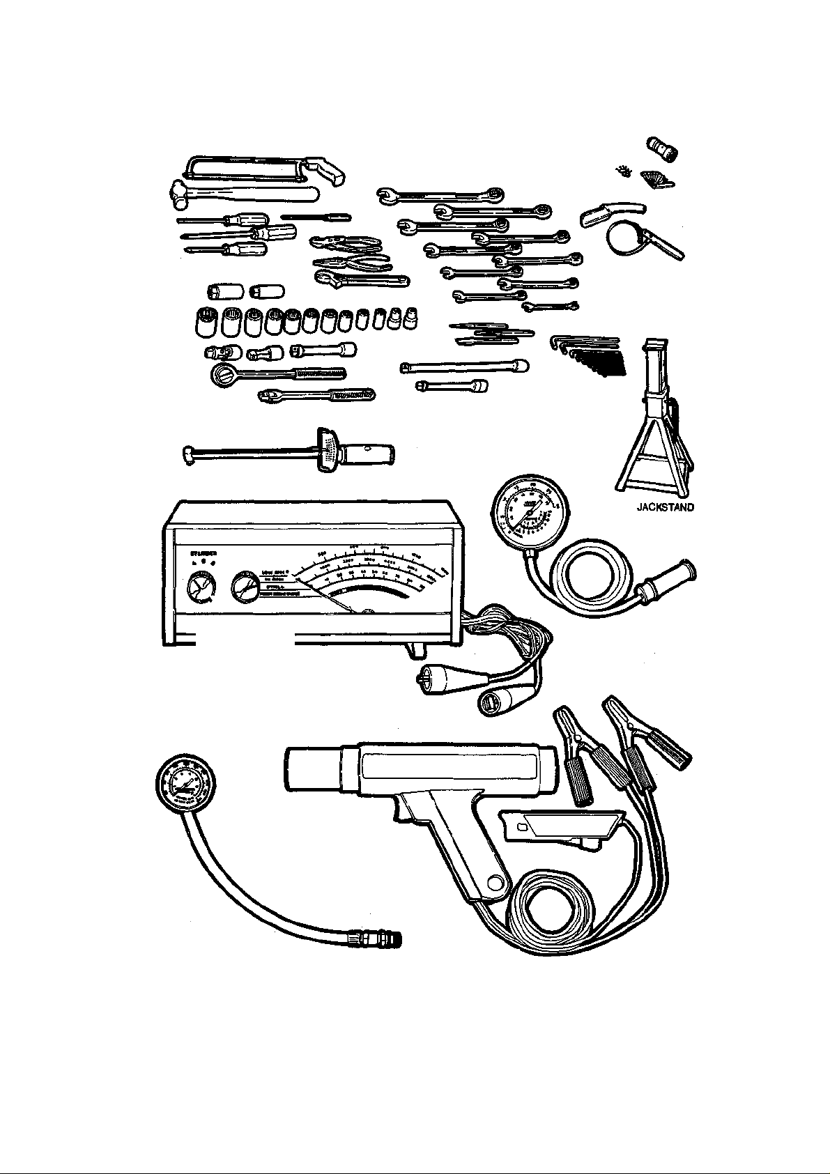
In addition to the normal assortment of
screwdrivers and pliers you should have the
following tools for routine maintenance jobs:
1. SAE (or Metric) or SAE/Metric
wrenches—sockets and combination open
end/box end wrenches in sizes from % in. (3
mm) to % in. (19 mm) and a spark plug socket
(13/ie or % in. depending on plug type).
If possible, buy various length socket drive
extensions. One break in this department is
that the metric sockets available in the U. S.
will all fit the ratchet handles and extensions
you may already have (¥4, %, and Yi in. drive);
2. Jackstands—for support;
3. Oil filter wrench;
4. Oil filler spout—for pouring oil;
5. Grease gun—for chassis lubrication;
6. Hydrometer—for checking the battery;
Page 7
COMPRESSION GAUGE
WRENCH
DWELL TACHOMETER
BEAM-TYPE TORQUE WRENCH
GENERAL INFORMATION AND MAINTENANCE 3
FROM TOP: BATTERY
TERMINAL TOOL;
FEELER GAUGES; OIL
SPOUT; FILTER
ALLEN WRENCHES
u/
DWELL/TACHOMETER
VACUUM GAUGE
TIMING LIGHT
You need only a basic assortment of hand tools and test instruments for most maintenance and repair Jobs
Page 8

4 GENERAL INFORMATION AND MAINTENANCE
7. A container for draining oil;
8. Many rags for wiping up the inevitable
mess.
In addition to the above items there are
several others that are not absolutely necessary, but handy to have around. These include oil dry, a transmission funnel and the
usual supply of lubricants, antifreeze and
fluids, although these can be purchased as
needed. This is a basic list for routine maintenance, but only your personal needs and
desire can accurately determine your list of
tools. If you are serious about maintaining your
own car, then a floor jack is as necessary as a
spark plug socket. The greatly increased utility, strength, and safety of a hydraulic floor
jack makes it pay for itself many times over
through the years.
The second list of tools is for tune-ups.
While the tools involved here are slightly
more sophisticated, they need not be outrageously expensive. There are several inexpensive tach/dwell meters on the market that
are every bit as good for the average mechanic as a $100.00 professional model. Just
be sure that it goes to at least 1,200-1,500
rpm on the tach scale and that it works on 4,
6 or 8 cylinder engines. A basic list of tuneup equipment could include:
1. Tach-dwell meter.
2. Spark plug wrench.
3. Timing light (a DC light that works from
the car's battery is best, although an AC light
that plugs into 110V house current will suf
fice at some sacrifice in brightness);
4. Wire spark plug gauge/adjusting tools.
5. Set of feeler blades.
Here again, be guided by your own needs.
A feeler blade will set the points as easily as
a dwell meter will read dwell, but slightly less
accurately. And since you will need a tachometer anyway . . . well, make your own
decision.
In addition to these basic tools, there are
several other tools and gauges you may find
useful. These include:
1. A compression gauge. The screw-in type
is slower to use, but eliminates the possibility
of a faulty reading due to escaping pressure.
2. A manifold vacuum gauge.
3. A test light, volt-ohm meter.
4. An induction meter. This is used for de
termining whether or not there is current in
a wire. These are handy for use if a wire is
broken somewhere in a wiring harness.
As a final note, you will probably find a
torque wrench necessary for all but the most
basic work. The beam type models are perfectly adequate, although the newer click type
are more precise.
Special Tools
Normally, the use of special factory tools is
avoided for repair procedures, since these are
not readily available for the do-it-yourself
mechanic. When it is possible to perform the
job with more commonly available tools, it
will be pointed out, but occasionally, a special tool was designed to perform a specific
function and should be used. Before substituting another tool, you should be convinced
that neither your safety nor the performance
of the vehicle will be compromised.
Some special tools are available commercially from major tool manufacturers. Others
can be purchased from your car dealer.
NOTE: Chevrolet special tools referred to in
this guide are available through the Service
Tool Division, Kent-Moore Corporation,
29784 Little Mack, Roseville, Ml 48066-
2298. In Canada, contact Kent-Moore of
Canada, Ltd., 2395 Cawthra Mississauga,
Ontario, Canada L5A 3P2.
SERVICING YOUR VEHICLE
SAFELY
It is virtually impossible to anticipate all of
the hazards involved with automotive maintenance and service but care and common
sense will prevent most accidents.
The rules of safety for mechanics range from
"don't smoke around gasoline," to "use the
proper tool for the job." The trick to avoiding
injuries is to develop safe work habits and take
every possible precaution.
Do's
• Do keep a fire extinguisher and first aid
kit within easy reach.
• Do wear safety glasses or goggles when
cutting, drilling, grinding or prying, even if
you have 20-20 vision. If you wear glasses for
the sake of vision, then they should be made
of hardened glass that can serve also as safety
glasses, or wear safety goggles over your reg
ular glasses.
• Do shield your eyes whenever you work
around the battery. Batteries contain sul
phuric acid; in case of contact with the eyes
or skin, flush the area with water or a mixture
Page 9

GENERAL INFORMATION AND MAINTENANCE 5
of water and baking soda and get medical attention immediately.
• Do use safety stands for any undercar
service. Jacks are for raising vehicles; safety
stands are for making sure the vehicle stays
raised until you want it to come down.
Whenever the vehicle is raised, block the
wheels remaining on the ground and set the
parking brake.
• Do use adequate ventilation when work
ing with any chemicals. Like carbon monox
ide, the asbestos dust resulting from brake
lining wear can be poisonous in sufficient
quantities.
• Do disconnect the negative battery cable
when working on the electrical system. The
primary ignition system can contain up to
40,000 volts.
• Do follow manufacturer's directions
whenever working with potentially hazard
ous materials. Both brake fluid and antifreeze
are poisonous if taken internally.
• Do properly maintain your tools. Loose
hammerheads, mushroomed punches and
chisels, frayed or poorly grounded electrical
cords, excessively worn screwdrivers, spread
wrenches (open end), cracked sockets, slip
ping ratchets, or faulty droplight sockets can
cause accidents.
• Do use the proper size and type of tool
for the job being done.
• Do when possible, pull on a wrench han
dle rather than push on it, and adjust your
stance to prevent a fall.
• Do be sure that adjustable wrenches are
tightly adjusted on the nut or bolt and pulled
so that the face is on the side of the fixed jaw.
• Do select a wrench or socket that fits the
nut or bolt. The wrench or socket should sit
straight, not cocked.
• Do strike squarely with a hammer—avoid
glancing blows.
• Do set the parking brake and block the
drive wheels if the work requires that the en
gine be running.
Dont's
• Don't run an engine in a garage or any
where else without proper ventilation—
EVER! Carbon monoxide is poisonous; it
takes a long time to leave the human body
and you can build up a deadly supply of it in
your system by simply breathing in a little
every day. You may not realize you are slowly
poisoning yourself. Always use power vents,
windows, fans or open the garage doors.
• Don't work around moving parts while
wearing a necktie or other loose clothing.
Short sleeves are much safer than long, loose
sleeves and hard-toed shoes with neoprene
soles protect your toes and give a better grip
on slippery surfaces. Jewelry such as watches,
fancy belt buckles, beads or body adornment
or any kind is not safe working around a car.
Long hair should be hidden under a hat or
cap.
• Don't use pockets for toolboxes. A fall or
bump can drive a screwdriver deep into your
body. Even a wiping cloth hanging from the
back pocket can wrap around a spinning shaft
or fan.
• Don't smoke when working around gas
oline, cleaning solvent or other flammable
material.
• Don't smoke when working around the
battery. When the battery is being charged,
it gives off explosive hydrogen gas.
• Don't use gasoline to wash your hands;
there are excellent soaps available. Gasoline
may contain lead, and lead can enter the body
through a cut, accummulating in the body
until you are very ill. Gasoline also removes
all the natural oils from the skin so that bone
dry hands will suck up oil and grease.
• Don't service the air conditioning system
unless you are equipped with the necessary
tools and training. The refrigerant, R-12, is
extremely cold and when exposed to the air,
will instantly freeze any surface it comes in
contact with, including your eyes. Although
the refrigerant is normally non-toxic, R-12
becomes a deadly poisonous gas in the pres
ence of an open flame. One good whiff of the
vapors from burning refrigerant can be fatal.
HISTORY
The 1963 Corvette Stingray is a complete departure from the Corvettes which preceded
it. The body, frame, and front and rear suspensions are all of new design. Engines and
transmissions are the only components that
were shared with the older models. Stingray
body styling evolved from the original William Mitchell Stingray sports/racing car which
competed in 1959-60. Fiberglass bodywork
was retained, but included a steel, reinforcing framework around the passenger compartment. The convertible model, with or
without hardtop, was retained and a new body
style added, the fastback coupe. Retractable
Page 10

6 GENERAL INFORMATION AND MAINTENANCE
headlights, rotated by two electric motors,
were also a new feature for the Corvette.
The frame is a ladder type with five crossmembers. The wheelbase has been reduced
from the 102 in. of previous models to a more
compact 98 in., and the rear track shortened
by 2 in. This, coupled with component relocation, resulted in a 48/52 percent front/rear
weight distribution; a marked improvement
over the 53 percent front weight bias of earlier model Corvettes. Overall body height was
reduced by 2 in. Front and rear suspensions
are both independent and newly designed for
the Stingray. The short/long arm front suspension has the upper arm tilted at an angle
of 9° for an anti-dive effect under braking.
Steering knuckles pivot in ball joints, instead
of the king pins and bushings of the early
Corvettes. The fully independent rear suspension is sprung with a nine-leaf transverse
spring. Universal-jointed axle driveshafts
transmit power to the wheels. Steering gear
is recirculating ball type and the linkage includes a hydraulic damper. Power steering
and brakes both became optionally available
for the first time on a Corvette. Brake drums
were enlarged and the brakes were made selfadjusting. Air conditioning became optionally available in kte 1963.
1964 saw detail body changes: functional
passenger-compartment exhaust vents and
elimination of the split rear window on the
coupe, removal of the non-functional vents on
the hood, and new wheel covers. The Muncie four-speed transmission, introduced in
mid-year 1963 to repkce the Borg-Warner T10, became the optional four-speed. The solid
lifter engines received larger intake and exhaust valves, and horsepower increased from
340 to 365 and from 360 to 375 for the carburetted and fuel-injected engines respectively. Transsistorized, breakerless ignition
became optionally available on high performance engines in 1964.
In 1965, the big change was the introduction of four-wheel disc brakes. Braking power
and fade resistance were greatly increased
over the drum brakes. A flat hood replaced
the 1964 hood which had twin indentations
and other body changes included restyled
wheel covers and functional exhaust vents
behind the front wheels. A new version of the
327 cubic inch engine was introduced, the 350
horsepower, hydraulic-cam option. In midyear, a 396 cubic inch 425 horsepower engine
was made available in the Corvette. 396 Corvettes were distinguished by the domed hood
required for carburetor clearance. Cars
equipped with the 396 received a larger front
stabilizer bar and the addition of a rear stabilizer bar. Side-mounted exhausts with
chambered mufflers joined the option list in
1965.
The 250, 365, and 375 horsepower engines
were dropped in 1966. The 300 horsepower,
327 cubic inch engine became the standard
power plant and the standard three-speed
transmission was synchronized in all forward
gears. The 396 was bored out to 427 cubic
inches and offered in two versions, a 425
horsepower and a milder 390 horsepower
model. A heavy-duty, four-speed transmission was introduced for use with the high
performance 427. Body changes included a
new, egg-crate grille, restyled wheel covers,
and the addition of backup lights.
1967 body styling changes included a hood
scoop on 427 Stingrays, more subdued exhaust vents on the front fenders, and a center
back-up light. Wheels were widened % inch
to 6 inches and were slotted. The full wheel
covers of former models were discarded for
trim rings and center caps. The handbrake
was changed to the pull-up type, and relocated to the center console. The 300, 350, and
390 horsepower engines remained the same
for 1967. A triple-two barrel carburetor setup was added to the 390 horsepower 427 engine which added an additional 10 horsepower. Also, the same carburetor arrangement was added to the former 425 horsepower
engine along with large port aluminum cylinder heads and a matching large port intake
manifold. The three-two barrel carburetion
also added 10 horsepower to this engine.
For the 1968 Corvette, a completely redesigned body and interior were installed on a
basically unchanged chassis. Many of the
styling features of the new body had been
previewed on the Mako Shark show car.
Overall body width and height were reduced, while front and rear tread increased
with the use of one inch wider wheels. The
convertible model was retained and the fastback coupe was replaced with a hardtop model
featuring removable roof panels and rear
window. Headlights on 1968 and later cars
are raised automatically, with vacuum power
when the lights are switched on. Wide oval
F70-15 tires repkced the 7.75-15 tires of previous years. The two-speed, Powerglide automatic transmission was superseded by the
three-speed Turbo Hydra-Matte, a significant improvement for general driving and
Page 11

GENERAL INFORMATION AND MAINTENANCE 7
performance usage. Engines remained the
same, except for the addition of the air-injection reactor pump to control exhaust emissions. Corvettes sold in California have been
equipped with the A.I.R. system since 1966.
Body styling remained die same for 1969
except for the addition of a Stingray script
above the engine exhaust vent. The doors
were slightly reshaped, widening the cockpit
by one inch at shoulder height. Wheel width
was increased to 8 inches, which also increased front and rear tread. The anti-theft
ignition, steering, and transmission lock were
introduced in 1969, with the ignition switch
mounted on the steering column. Side exhausts were offered for the first time on the
new body in 1969. Headlight washers were
now included in the standard equipment. The
small block stroke was increased to give a displacement of 350 cubic inches; however, horsepower ratings remained the same. 427 engine options remained the same for 1969 with
the exception of the redesigned L88 engine.
The 2nd design L88 used a large-port aluminum intake manifold with a single 850 cfin
Holley carburetor, aluminum large-port open
chamber cylinder heads, special camshaft with
solid lifters, and redesigned HD connecting
rods with 7/ie rod bolts. Also, the rare ZL-1
427 engine was an option on models of this
year. The ZL-1 had the same horsepower rating of the L88 (430 hp) and shared many internal components with the L88. The rarity
of the ZL-1 engine comes with the fact that it
used an aluminum cylinder block with cast
iron cylinder liner sleeves.
A new grille, larger parabolic reflector turn
signals, and wheel well flares were added to
the Stingray body for 1970. Cast metal grilles
were added over the engine compartment
exhaust vents and the tailpipe exits were made
retangular. The seats were redesigned, lowering them one inch for more headroom and
making the headrests integral. The 427 stroke
was increased for 1970 to give a displacement
of 454 cubic inches. Triple, two-barrel carburetion was dropped from the big blocks in
1970. A 370 horsepower 350 cubic inch engine, the LT-1, was introduced to answer the
need for a solid lifter, high rpm small block
engine. The three-speed, manual transmission was discontinued in 1970, and the fourspeed transmission and Positraction rear axle
were made standard equipment.
Horsepower was decreased in 1971 through
an across-the-board compression reduction.
The 350 horsepower, hydraulic-cam version
of the small block was deleted from the option list.
1972 saw very few changes made to the
Corvette. Rated horsepower was again down,
due mostly to a new rating system which uti
lizes net instead of gross power outputs. The
audio alarm antitheft system is not a standard
item, and the fiber optic light monitors have
been discontinued. Only three engines are
offered for 1972, two 350 cubic inch engines
and one 454 cubic inch engine. There were
no body changes, except for the addition of
four new colors.
1973 saw the Corvette receive a new front
end with a resilient body color bumper. The
cool air induction hood covers the windshield
wipers, allowing the wiper door and mecha
nism to be eliminated. New body mounts and
extra soundproofing were also added for 1973.
GR70-15 steel-belted radial tires are stan
dard equipment. As far as the small-block en
gines are concerned, the LT-1 engine was
discontinued for this model year. The succes
sor to the LT-1 engine was the L82 high per
formance engine which used the same short
block as the LT-1 but through the use of a
hydraulic camshaft and a Quadrajet carbu
retor, the engine was again down on power.
The 454 Turbo-jet was also available with a
rating of 275 horsepower.
1974 was a year of very little change for the
Corvette. A resilient rear section was added
similar to the front system introduced in 1973.
Three engines continued to be available, ex
cept in California where only the two 350s
were available.
Changes to the 1975 Corvette include a
catalytic reactor to reduce emissions, a fuel
cell-type fuel tank, and the dropping of the
454 engine.
Only one Corvette body style was available
for 1976, the convertible was dropped. The
Turbo Hydra-Matic 350 replaced the 400 on
the base engine. A partial steel underbody
replaced the traditional fiberglass, which both
improved body strength and heat protection
from the exhaust system.
1977 was a year of refinements and a
slight appearance change from the 1976
model.
The 1978 Corvette received its most extensive change since its introduction of the current series in 1968 with a new fastback roof
line resulting in a new cockpit design and a
larger cargo area. A larger 24 gallon fuel cell
type fuel tank is used for greater fuel capacity. Increased horsepower and torque ratings
Page 12

8 GENERAL INFORMATION AND MAINTENANCE
are achieved for the special performance engine over the base engine as a result of improvements of the induction and exhaust systems. The base engine uses a Muncie 4-speed
manual transmission while the special performance engine uses a Borg-Warner. Both engines use the same Turbo Hydra-Matic transmission.
1979 was a year of very little change with
slight refinements of performance and appearance.
In 1980, the Corvette weight reduction plan
was initiated. The following components were
lightened to reduce the weight of the Corvette: front and rear bumper systems, hood,
door panels, windshield and door glass (reduced thickness), selected frame members,
and exhaust system. Appearance changes for
1980 include an integral front air dam, deeply
recessed front grilles with integral parking
lamps, cornering lamps, integral rear spoiler
and functional black louvers on the front
fenders. Transmission changes include the use
of a locking torque convertor with the automatic transmission, and new gear ratios for
the 4-speed manual transmission. Engine
availability remains unchanged except for
California models. California powertrain
availability is limited to the new (to the Corvette) 305 engine with an automatic transmission. Miscellaneous components relating to
drive train weight loss include the use of an
aluminum intake manifold on the L82 engine, stainless steel exhaust manifolds on the
305 California engine, and a new aluminum
differential mounting for all models.
The 1981 Corvette has only slight improvements in appearance and convenience
items compared to the previous year. Both
350 engines (L48 and L82) and the 305 have
been discontinued for 1981. A new L81 3504 bbl. engine is the only engine available for
1981. The Corvette recorded an industry first
this year through the introduction of an FRP
(Fiberglass Reinforced Plastic) rear spring
which replaces the previous mutli-leaf metal
rear spring assembly.
In 1982, appearance and convenience item
changes are again minimal. The 350 4-bbl.
engine has been discontinued and a 350 engine with twin-throttle body fuel injection
(TBI) was introduced. The twin TBI system,
referred to as "Cross-fire Injection" by the
Chevrolet marketing force, is said to improve
both throttle response and fuel economy as
compared to the previous 4-bbl. carburetion
system. Also, a new 4-speed automatic overdrive transmission with a locking torque con-
vertor is the only transmission available in
1982.
There is no 1983 Corvette model, but the
1984 Corvette is the first completely new design in over fifteen years. A new uniframe design body structure incororates high technology components such as forged aluminum
suspension arms and fiberglass transverse leaf
springs. The much-improved performance and
handling characteristics of the 1984 Corvette
continues the tradition of the ultimate American sport car. The L83 350 V8 with Cross
Fire Fuel Injection is the only available engine in the 1984 Corvette, but two transmissions are offered. The THM 700 R4 automatic is standard, with an 83 mm 4 speed
manual with automatic overdrive optional. The
power rack and pinion steering and Z-51 sus pension package combine to provide precision and predictability at all speeds, along with
the highest lateral acceleration figure (.95G)
ever recorded for a production model at the
CM Proving Grounds.
Corvettes have proven themselves in all
types of automotive competition, and the
Stringray has continued to bear the Corvette
standard in many forms of racing. A Stingray
coupe won the first race entered in October
1962 at Riverside Raceway. Since then, Corvettes have continued their winning ways in
road racing in the SCCA A and B-Production
classes. Corvettes have also taken numerous
trophies in drag racing, in both the stock and
modified classes. Sebring, Daytona, and Le
Mans have witnessed many Corvette entries;
Corvettes have placed well overall and succeeded in winning the GT class several times
at these endurance races. The aerodynamic
Stingray has also been utilized several times
in setting Grand Touring class records during
the Bonneville Speed Weeks. Just recently,
a stock-bodied 1968 Corvette roadster
equipped with a twin-turbocharged 430 cid
big-block engine broke the stock-bodied record at Bonneville with two 240+ mph runs.
That racing improves the breed has certainly
proved to be true in the case of the Corvette,
with many race-proven pieces having become standard equipment or options on production Corvettes.
SERIAL NUMBER
IDENTIFICATION
Vehicle
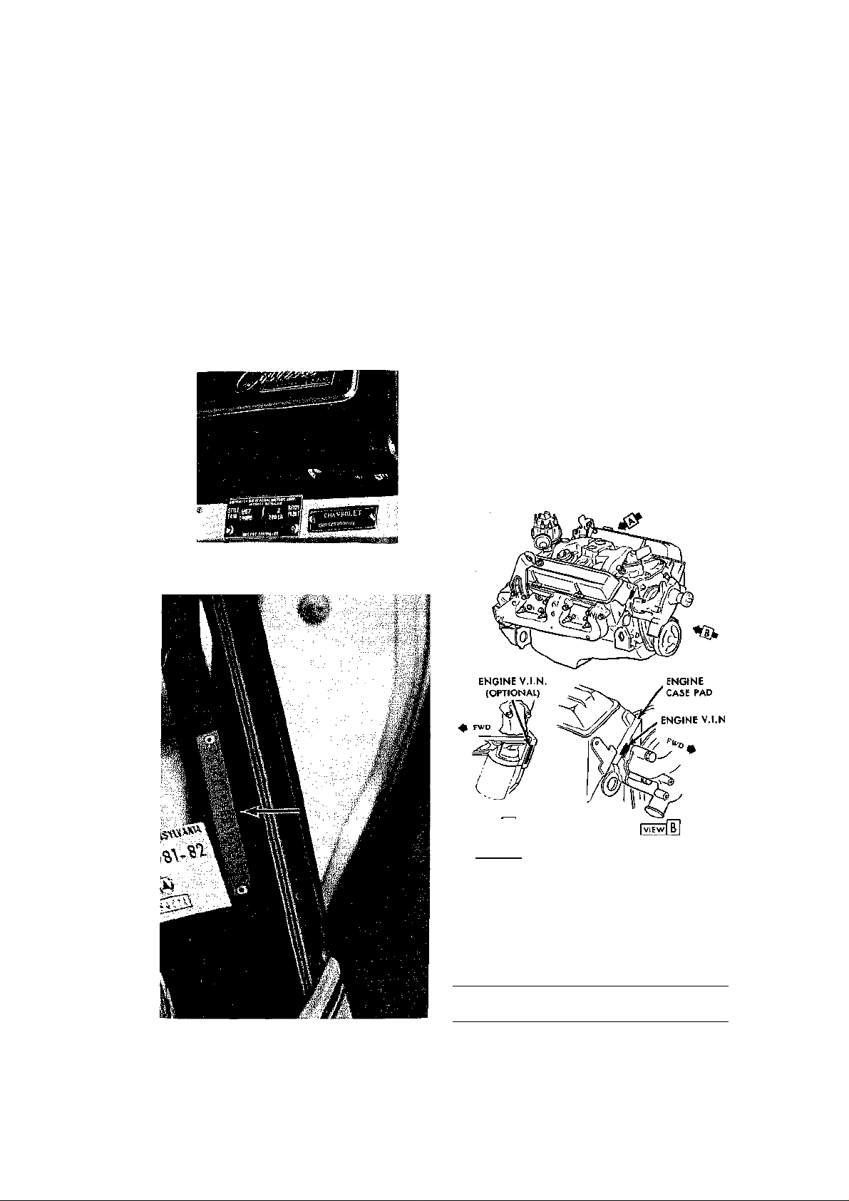
The 1963 through 1967 Corvette vehicle serial number, body style, body trim number,
Page 13
GENERAL INFORMATION AND MAINTENANCE 9
1
5645
and paint combination is located on the instrument panel reinforcing member directly
under the glove compartment. The vehicle
serial number plate is located on the top left
of the instrument panel (1968—76) and on the
inside left windshield pillar post (1977-82).
The body, trim, and paint number plate is
located on the upper left hand door hinge pillar (1968-78) and on the upper horizontal
surface of the shroud (1979—84). The vehicle
serial number identifies die body style, model
year, assembly plant, engine usage (1976-84),
and production number.
1963-67 vehicle serial number location
INTERPRETING THE SERIAL NUMBER
A typical vehicle serial number tag yields
manufacturer's identity, vehicle type, model
year, engine type, assembly plant and production unit number when broken down as
shown in the following charts.
Engine
All Corvette engine identification numbers
are stamped on a pad of the engine block
which is located at the lower front edge of the
right side cylinder head. The first letter designates the plant in which the engine was
manufactured and the numbers which follow
identify the production date. The two or three
letter suffix identifies the engine type and related equipment. On 1972 and later models,
if the engine in the vehicle is known to be
original, the fifth digit (1972-80) and the
eighth digit (1981-84) of the serial number
may also identify the engine used in the vehicle.
Serial number location on the drivers side windshield pillar—1977-82 models
|VIEW|A| Typical engine serial number
location
Mir
Identity
V.I.N. Chart 1963-71
Body
1
Style
Model
2
Year
3
1
assigned to all Chevro
let built vehicles
2
Model identification
3
Last number of model year (1968)
4
F-Flint
5
Unit numbering will start at 100,001 at all plants
Manufacturer's identity number
Assy
Plant"
Unit
5
No.
100025
Page 14

10 GENERAL INFORMATION AND MAINTENANCE
1G1
9
N
47
Restraint Basic
Mfr.
1
Identity
1
Manufacturers identity number assigned to all Chevrolet built passenger cars
2
A—Non-passive restraint with manual seat belts
3
Y—Corvette
"87—Two door hardtop coupe
5
Engine code : 6(1981), 8(1982-84)
6
Manufacturers use only
7
B—1981, C—1982, E—1984, etc.
8
S—St. Louis, 5—Bowling Green
9
9—Unit numbering varies depending upon model
System
2
Type
Car
Model
V.I.N. Chart 1972-80
Mfr Series
Iden- Code Body Engine Model bly Num flty1 Letter2 Style3 Model4 Year5 Plant6 her
1
assigned to all Chevro
let built vehicles
2
Model identification
3
Model identification
"Engine code
5
Last number of model year (1974) 6F-
Flint
7
Unit numbering will start at 000001 or 100,001 depend-
ing on the model
1
Manufacturer's identity number
Engine Identification
1963-64 327
cubic inch engine
Manual transmission RC
Manual transmission and high performance RD
Special high performance RE
Manual transmission and fuel injection RF
Powerglide SC
Powerglide and high performance SD
cubic inch engine
Manual transmission and A/C RP
Manual transmission, high performance, RQ
A/C
Manual transmission, special high perfor- RR
mance, A/C
Manual transmission and transistor ignition RT
Fuel injection and transistor ignition RX
Manual transmission, transistor ignition, A/C RU
Powerglide and A/C SK
Powerglide, high performance, A/C SL
cubic inch engine
Manual transmission HE
High performance HF
Fuel injection HG
Special high performance HH
A/C HI
High performance and A/C HJ
1964 327
1965 327
V.I.N. Chart 1981-84
7
100025
Engine
Model
Body
3
Type"
400.001
87
Assem- Unit
5
Check
Digit"
Model
Year
Engine Identification (cont.)
cubic inch engine
Special high performance and A/C HK
Transistor ignition HL
Transistor ignition and A/C HM
Fuel injection and transistor ignition HN
Powerglide HO
Powerglide and high performance HP
Powerglide and A/C HQ
Powerglide, high performance, A/C HR
Special high performance and hydraulic HT
lifters
Special high performance, hydraulic lifters, HU
A/C
Special high performance, hydraulic lifters, HV
transistor ignition
Special high performance, hydraulic lifters, HW
transistor ignition, A/C
396 cubic inch engine
Special high performance IF
cubic inch engine
Manual transmission HE
A.I.R. HH
A.I.R. and Powerglide HR
Special high performance and A.I.R. HD
Powerglide HO
Special high performance HT
Power steering, special high performance, HP
A.I.R.
Special high performance, A/C, A.I.R. KH
427 cubic Inch engine
Special high performance and hydraulic IK
lifters
High performance IL
A.I.R. IM
Special high performance IP
Powerglide IQ
Powerglide and A.I.R. IR
cubic inch engine
Manual transmission HE
A.I.R. HH
7
1965 327
1966 327
1967 327
Assy.
8
Plant
Unit
9
Number
Page 15

GENERAL INFORMATION AND MAINTENANCE 11
LV
LX
CTL
CTM
CTN
CTO
CTP
CTQ
CTR
CRI
CJL
CGY
CPJ
CPX
CKW
CRS
Engine Identification (cont.)
1967 327 cubic
Inch engine
A.I.R. and Powerglide HR
Special high performance and A.I.R. HD
Powerglide HO
Special high performance HT
Power steering, special high performance, HP
A/C
Special high performance, A/C, A.I.R. KH
427 cubic Inch engine
4-speed or Powerglide IL
Triple carburetion JC
A.I.T., special high performance, triple JE
carburetion
Heavy duty IT
Aluminum heads ID
A.I.R. IM
A.I.R. and triple carburetion JF
A.I.R. and aluminum heads JH
Powerglide IQ
Powerglide and triple carburetion JD
A.I.R. and Powerglide IR
A.I.R., triple carburetion, Powerglide JG
A.I.R., special high performance, triple JA
carburetion
1968 327 cubic
inch engine
Manual transmission HE
Turbo Hydra-Matic HO
Power steering and A/C HP
Special high performance HT
427 cubic inch engine
High performance IL
High performance and triple carburetion IM
High performance, triple carburetion, Turbo IO
Hydro-Malic
Turbo Hydra-Matic IQ
Special high performance and triple car- IR
buretion
High performance IT
Special high performance, triple carbure- ID
tion, aluminum heads
1969 350 cubic
inch engine
High performance HW
High performance and A/C HX
Manual transmission HY
Turbo Hydra-Matic HZ
427 cubic inch engine
High performance, Turbo Hydra-Matic LL
High performance LM
Triple carburetion, high performance, Turbo LN
Hydra-Matic
Heavy duty (L88) LO
Aluminum heads LP
Triple carburetion and high performance LQ
Triple carburetion and special high perfor- LR
mance
Engine Identification (cont.)
427 cubic inch engine
Triple carburetion, special high performance,
heavy duty clutch Heavy duty and Turbo
Hydra-Matic Triple carburetion, special high
performance, Turbo Hydra-Matic
1970 350 cubic
inch engine
Manual transmission
Turbo Hydra-Matic
High performance
High performance and A/C/
High performance and transistor ignition
High performance, transistor ignition, A/C
Special high performance
Special high performance and transistor ig-
nition
Special high performance, transistor ignition,
4-speed
High performance, 4-bbl carburetor, Turbo
Hydra-Matic
High performance, 4-bbl carburetor, transistor
ignition
454 cubic inch engine
High performance, 4-bbl carburetor, Turbo
Hydra-Matic
High performance and 4-bbl
Heavy duty with 4-bbl
Heavy duty with 4-bbl and Turbo Hydra-Matic
High performance, 4-bbl, transistor ignition
1971 350 cubic
inch engine
270 hp, 4-speed 270 hp, THM 330 hp, 4speed 330 hp, THM 330 hp, 4-speed (HD)
454 cubic inch engine
365 hp, THM 365 hp, 4-speed 425 hp, 4speed 425 hp, THM
1972 350 cubic
inch engine
200 hp with 4-speed
200 hp with 4-speed and NOX control
(Calif.)
200 hp with Turbo Hydra-Matic 200 hp with
Turbo Hydra-Matic and NOX
control (Calif.) 255 hp with 4-speed 255 hp
with Turbo Hydra-Matic 255 hp with 4-speed
and A.I.R. 255 hp with Turbo Hydra-Matic and
A.I.R.
LU
CTU
CTV
CZN
CGW
CZU
CZL
CZN
CRI
CGT
CGZ
CJK
CPH
CPW
CDH
CKX
CDJ
CKY
CKZ
CRT
Page 16

12 GENERAL INFORMATION AND MAINTENANCE
350 (L83)
CLR
CLS
CUT
CMS
ZAC
ZAA
ZAB
ZAD
ZBA
ZBB
ZCA
ZAM
ZAK
ZBD
ZBC
ZDA
ZDC
ZDD
ZDB
ZBA
ZBC
Engine Identification (cont.)
454 cubic Inch engine
270 hp with 4-speed CPH
270 hp with Turbo Hydra-Matic CPJ
270 hp CSR.C
inch engine
190 hp with 4-speed CKZ
190 hp with 4-speed (Calif.) CLB
190 hp with Turbo Hydra-Malic CLA
190 hp with Turbo Hydra-Matic (Calif.) CLC
250 hp with 4-speed CLR
250 hp with 4-speed (Calif.) CIS
250 hp with Turbo Hydra-Matic CLD
250 hp with Turbo Hydra-Malic (Calif.) CLH
454 cubic inch engine
275 hp with 4-speed CWM
275 hp with 4-speed (Calif.) CWT
275 hp with Turbo Hydra-Matic CWR
275 hp with Turbo Hydra-Matic (Calif.) CWS
cubic inch engine
195 hp with 4-speed CKZ
195 hp with 4-speed (Calif.) CLB
195 hp with Turbo Hydra -Matic CLA
195 hp with Turbo Hydra-Matic (Calif.) CLC
250 hp with 4-speed CLR
250 hp with 4-speed (Calif.) CLS
250 hp with Turbo Hydra-Matic CLD
250 hp with Turbo Hydra-Matic (Calif.) CLH
454 cubic inch engine
270 hp with 4-speed CWM
270 hp with 4-speed (Calif.) CWT
270 hp with Turbo Hydra-Matic CWR
270 hp with Turbo Hydra-Matic (Calif.) CWS
cubic inch engine
195 hp with 4-speed CRJ, CUA, CUB
195 hp with Turbo Hydra-Matic CRK
250 hp with 4-speed CRL, CUT, CUD
250 hp with Turbo Hydra-Matic CRM
cubic inch engine
180 hp, 210 hp
cubic inch engine
180 hp, 210 hp
inch engine
185 hp (Calif.)
185 hp (high altitude)
1973 350 cubic
1974 350
1975 350
1976 350
CLM, CLR, CLS,
CKW, CKX, CLS,
CHC, CHR, CKC
1977 350
CKZ, CLA, CLB,
CLC, CHD, CKD,
CLD, CLF
1978 350 cubic
Engine Identification (cont.)
inch engine
185 hp AT. (Fed.) 185hpM.T. 225 hp M.T.
225hpA.T.
195 hp (Calif.)
195 hp with 4-speed
195 hp with Turbo Hydra-Matic
195 hp (High altitude)
225 hp with 4-speed
225 hp with Turbo Hydra -Matic
305 engine
Std. 350 eng. (L48) w/M.T. Std. 350 eng.
(L48) W/A.T. Hi Pert. 350 eng. (L82) w/M.T.
Hi pert. 350 eng. (L82) w/A.T.
Federal models w/M.T. Calif, models w/M.T.
Federal models w/AT. Calif, models w/A.T.
Federal models Calif, models
1978 350 cubic
1979
1980
1981
1982
1984
CLM
CMR
ZFC, ZFD, ZFF,
ZFN, ZFM
Transmission
5.7L EFI
number is located on a boss above the filler
plug. The Borg-Warner T-16, 3-speed serial
number is located on a boss at the right rear
corner of the transmission extension.
FOUR-SPEED MANUAL
Serial numbers of 4-speed transmissions used
in models prior to 1979 are located at one of
the three following locations: left side cover
flange; left side of the case to the rear of the
cover; or the left side of the case below the
side cover.
1979 and later transmission I.D. numbers
are located on a flange at the right side top of
the case.
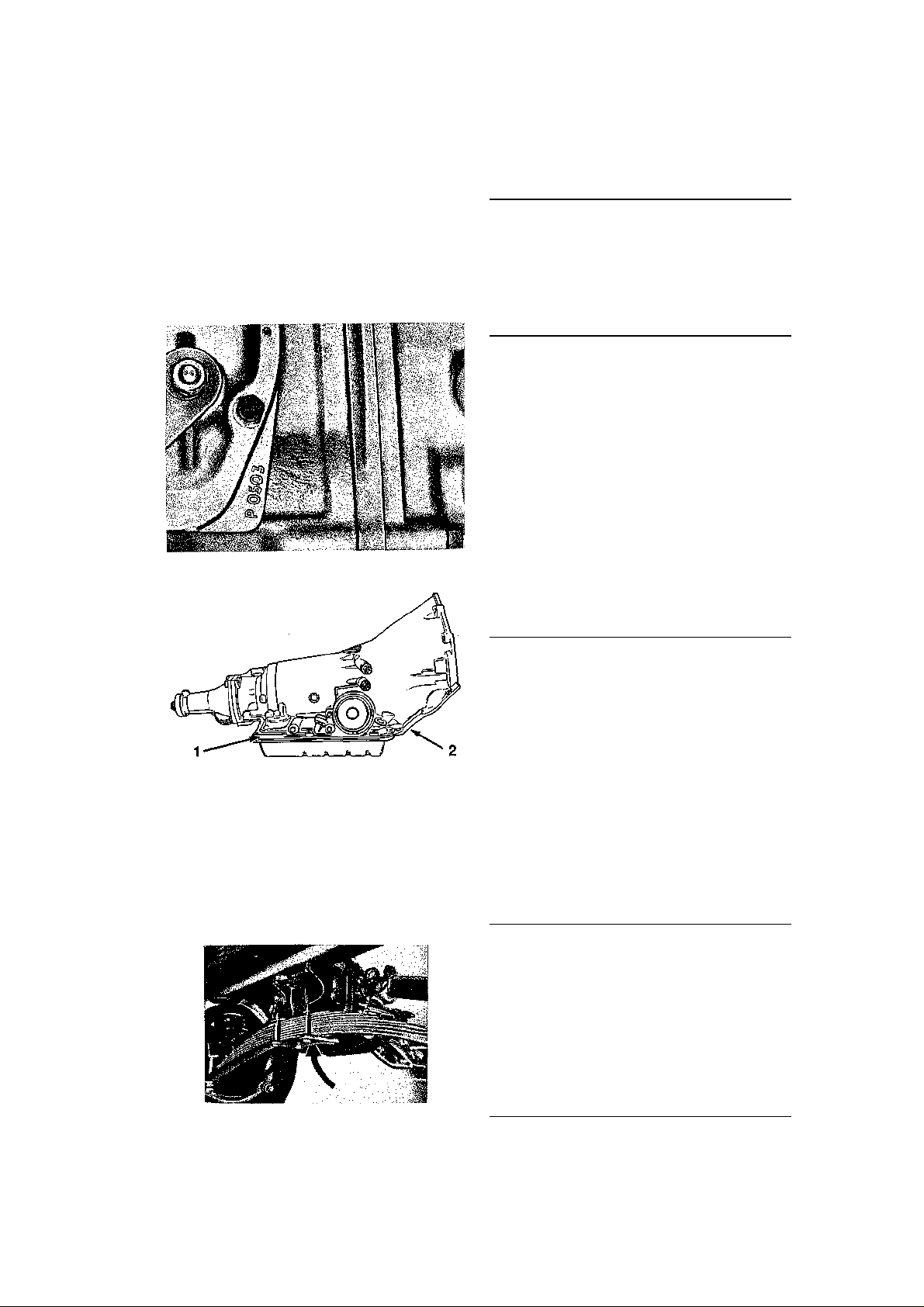
TURBO HYDRA-MATIC
1978 and prior THM 350 serial numbers are
located on the right side vertical face of the
transmission oil pan.
THREE-SPEED MANUAL
The Muncie 3-speed serial
Page 17
GENERAL INFORMATION AND MAINTENANCE 13
3.55 Positraction
3.08 Positraction
3.55 Positraction
4.11 Positraction
396 engine
3.36
Positraction with
3.36 Positraction
3.08 Positraction
427 engine
3.36
427 engine
4.1 1
427 engine
4.56
Positraction with
3.55 Positraction
4.11 Positraction
1979 and later 3-speed automatic transmissions are coded either on the right side of the
case above the front of the oil pan or on the
case above the left rear of the oil pan. The
THM 400 and the THM 700-R4 4-speed automatic transmissions serial number is located on a tag attached to the transmission
case above the right rear corner of the oil
pan.
Muncie 4-speed serial number location
Typical automatic transmission stamped serial
number location (1) and VIN number location (2)
Rear Axle
All Corvette Stingrays have the rear axle serial number located on the bottom surface of
the carrier at the cover mounting flange. The
two or three-letter prefix in the serial number identifies the rear-axle gear ratio.
Rear axle serial number
Rear Axle Ratio Identification
Year
1963-64
1965
1966
1967
Axle Ratio and Type
Prefix
CA
CJ
CB
CC
CD
CE
CF
CZ
CX
AK
AL
AM
AN
AO
AP
AQ
AR
AS
AT
AU
AZ
FA
FB
FC
AK
AL
AM
AN
AO
AP
AR
AS
AT
AU
AZ
FA
FB
FC
AK
AL
AM
AN
AO
AP
AS
AT
AU
AZ
3.36 with 3-speed
3.08 Positraction
3.36 Positraction
3.70 Positraction
4.11 Positraction
4.56 Positraction
3.08 with 4-speed
3.70 with 4-speed
3.36
3.36 Positraction
3.70 Positraction
4.56 Positraction
3.08
3.70 with 4-speed 3.08
Positraction with
Positraction with
396 engine 3.55
Positraction with
396 engine 3.70
Positraction with
396 engine 4.11
396 engine 4.56
Positraction with
396 engine
3.36
3.08 Positraction
3.55 Positraction
3.70 Positraction
4.11 Positraction
3.70 with 4-speed 3.08
Positraction with
Positraction with
427 engine 3.55
Positraction with
427 engine 3.70
Positraction with
Positraction with
427 engine
3.36
3.08 Positraction
3.36 Positraction
3.70 Positraction
3.70 with 4-speed 3.08
Positraction with
427 engine 3.36
Positraction with
427 engine 3.55
Positraction with
427 engine
Page 18

14 GENERAL INFORMATION AND MAINTENANCE
427 engine
FB
4.1 1 Positraction with
427
engine
FC
4.36 Positraction with
1968
3.36"
3.08 'Positraction
AM
3.36 Positraction
3.55 Positraction
3.70 Positraction
AP
4.11 Positraction
3.70
3.08 Heavy duty Positraction
AU
3.36
HeaVy duty Positraction
AV
3.08 Posjtraction
1969
3.08 Positraction
3.36 Positraction
3.55 Positraction
AO
3.70 Positraction
4.11 Positraction
3.70
3.08 Heav
y duty Positraction
3.36 Heavy duty Positraction
AV
3.08 Heavy duty Positraction
2.73 Heavy duty Positraction
3.55 Heavy duty Positraction
FA
3.70 Heavy duty Positraction
4.11 Heavy duty Positraction
3.08 Positraction
CAM
3.36 Positraction
3.55 Positraction
3.70 Positraction with
high performance 350
and close
-
ratio 4
-
speed
CAP
4.11 Positraction
3.08 Positraction
3.36 Positraction
CAV
3.08 Positraction
3.08 Positraction with
Turbo Hydra
-
Matic
CAY
2.73 Positraction
3.36 Positraction with
Turbo Hydra
-
Matic
CAZ
3.70 Positraction
4.11 Positrac
tion
CFC
4.56 Positraction
3.55 Positraction
3.70 Positraction
AC
4.11 Positraction
4.56 Positraction
3.08 Positraction
Rear Axle Ratio Identification
Year
1970
CAK
1971
AA
FA
AK
AL
AN
AO
AS
AT
AW
AK
AL
AM
AN
AP
AS
AT
AU
AW
AY
AZ
FB
FC
CAL
CAN,
CAO,
CAS
CAT
CAU
CAW
CAX
CFA
CFB
CLR
AB
AD
AW
AX.LR
Prefix
(cont.)
Axle Ratio and Type
3.70 Positraction with
427 engine
3.08 Heavy duty Positraction
3.36
4.56 Positraction
3.36
3.36 Positraction
3.36 Positraction
Rear Axle Ratio Identification
(cont.)
Year Prefix
1972 -75
1976-77
1978
1979
1980 DANA
1981
1982 DANA
1984 DANA
AX, LR
AC AB
AA AW
AV
OA LR,
OD OB
OC
OK
OM
OH
OJ
OM
OH
OJ
OJ
OK
Axle Ratio and Type
3.36 Positraction
4.11 Positraction
3.70 Positraction
3.55 Positraction
3.08 Positraction
2.73 Positraction
3.08 Positraction
3.36 Positraction
3.55 Positraction
3.70 Positraction
3.08 Positraction
3.36 Positraction
3.55 Positraction
3.70 Positraction
3.36 Positraction
3.55 Positraction
3.70 Positraction
3.07 Positraction
2.87 Positraction w/A.T.
2.72 Positraction w/M.T.
2.87 Positraction
3.07 Positraction
3.31 Positraction
ROUTINE MAINTENANCE Air
Cleaner
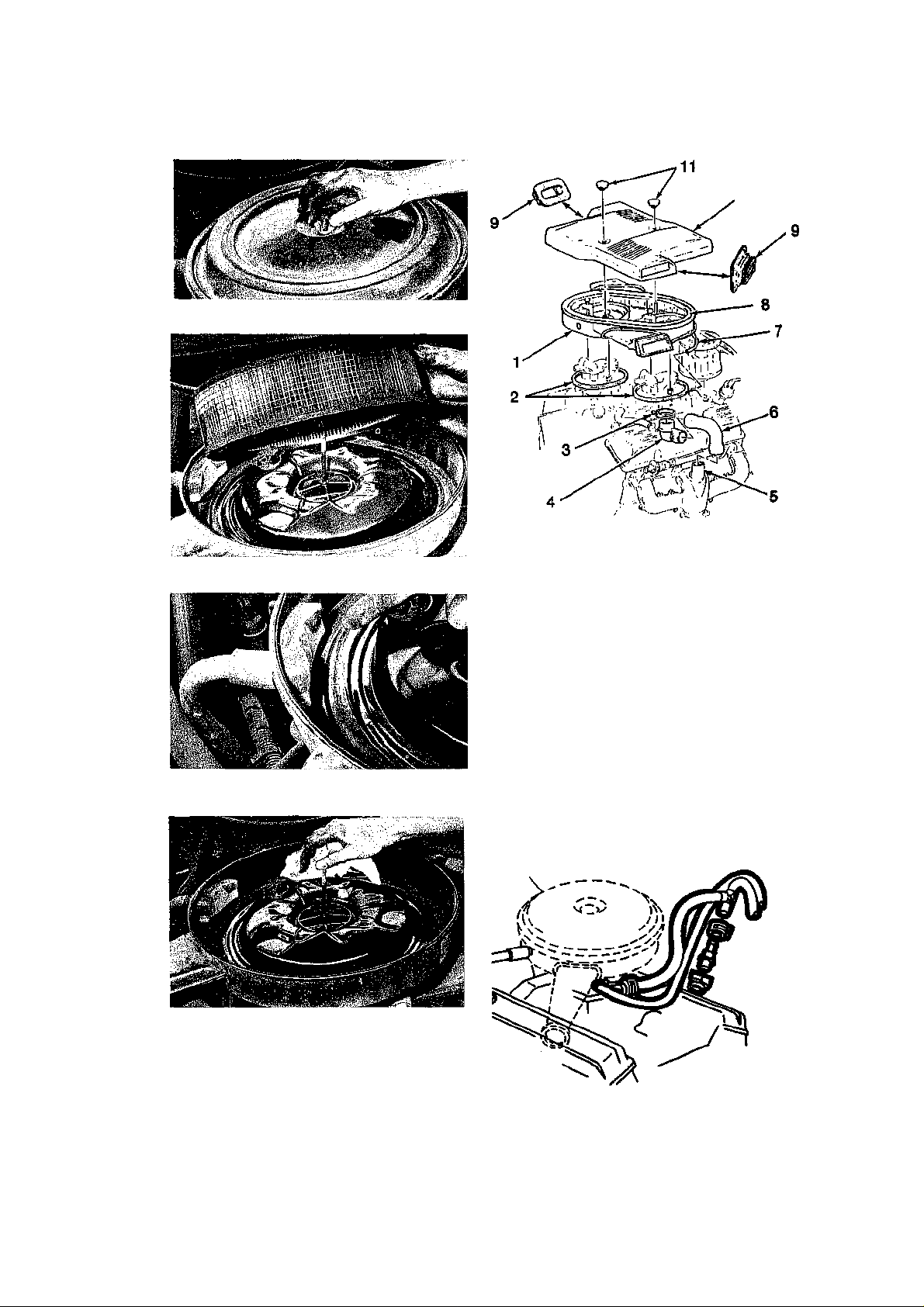
The air cleaner consists of a metal housing for
a replaceable paper filter or permanent
polyurethane element and the necessary
hoses connecting it to the crankcase ventilation system. The air cleaner cover is held by
a wing nut on all models. If your Corvette is
equipped with a paper element, the factory
recommends it should be replaced once every
12,000 miles (1963-72), every 24,000 miles
(1973-74), every 30,000 miles (1975-84). Inspection and replacement should come more
often when the car is operated under dusty
conditions. To check the effectiveness of your
paper element, remove the air cleaner assembly and, if the idle speed increases noticeably, the element is restricting airflow and
should be replaced. Some high-performance
models or cars equipped with optional air
cleaners use a polyurethane element that
must be removed, cleaned, and reoiled at
12,000 mile or 12 month intervals. Remove
the filter and clean it in kerosene. Do not use
paint thinner or similar solvent and then
squeeze it dry. Allow it to soak in SAE 30 oil
Page 19
GENERAL INFORMATION AND MAINTENANCE 15
10
Remove and discard the old filter
—
PCV VALVE
The PCV valve is located in the rocker arm cover
on later models
Unscrew the wing nut and remove the cover
1. Air cleaner assembly 7. Manifold vacuum hose
2. Gasket 8. Air filter element
3. Hose clamp 9. Hood seal
4. Heat stove adapter 10. Air cleaner cover
5. Heat stove 11. Knurl nuts
6. Heat stove tube
Air cleaner assembly—1984 TBI shown
Check the small crankcase breather
Using a clean rag or a paper towel, wipe out the
inside of the air cleaner
and again squeeze it dry using a clean cloth
to remove excess oil. Clean the inside of the
air cleaner housing before reinstalling either
type of filter.
Positive Crankcase Ventilation
(PCV)
The PCV valve is screwed into the carburetor
or located in the ventilation hose on 1963
models. 1964 and 1965 models are not
equipped with a PCV valve, but use a metered orifice fitting instead. This is not replaced, as it is a permanent part of the system, but it should be cleaned with solvent as
a part of regular maintenance. The PCV valve
AIR CLEANER
Page 20

16 GENERAL INFORMATION AND MAINTENANCE
BATTERY TOP
BATT
ERY TOP
BATTERY TOP
STARTED
is located in the hose or in the rocker cover
on later models. Replace the PCV valve and
if so equipped the PCV filter, located in the
air cleaner, every 12,000 miles (1963-71),
every 24,000 miles (1972-74), every 30,000
miles (1975-84).
Evaporative Emissions Control
System
This system, standard since 1970, eliminates
the release of unburned fuel vapors into the
atmosphere. The only periodic maintenance
required is an occasional check of the connecting lines of the system for kinks or other
damage and deterioration. Lines should be
replaced only with quality fuel line or special hose marked "evap." Every 12,000 miles
or 12 months (1970-71), every 24,000 miles
or 24 months (1972-74), every 30,000 miles
or 24 months (1975-81), the filter in the bottom of the carbon canister which is located in
the engine compartment should be removed
and replaced. This service is not required on
1982 and later models.
Battery
The major cause of slow engine cranking or a
"no-start" condition is battery terminals which
are loose, dirty, or corroded. Every 3 months
or so, disconnect the battery and clean the
terminals of both the battery and the cables.
Cleaning tools for this purpose are available
at most any auto parts store. When you buy
a cleaning tool, be sure to specify whether
you have a top terminal or side terminal battery, as the type of tool differs depending
upon the style of battery. After you clean the
terminals and reconnect the battery, apply a
corrosion inhibitor to the terminals. Stay away
from using any substance which is not meant
specifically for this purpose. Do not apply the
corrosion inhibitor to the mating surfaces of
the terminals unless specified by the chemical manufacturer.
Batteries themselves can be cleaned using
a solution of baking soda and water. Surface
coatings on battery cases can actually conduct
electricity which will cause a slight voltage
drain, so make sure the battery case is clean.
Unless you have a "maintenance-free" bat-
tery, check the electrolyte level in the battery (see Battery under Fluid Level Checks
in this chapter). Be sure that the vent holes
in the caps and the vent tubes are not blocked
with grease or dirt. The vent system allows
DARKENED
INDICATOR
(WITH GREEN
DOT)
MAY BE JUMP
Maintenance-free batteries contain their own
built-in hydrometer
DARKENED
INDICATOR (NO
GREEN DOT)
MAY BE JUMP
STARTED
hydrogen gas, formed by the chemical reac-
tion in the battery, to escape freely. If your
vehicle is equipped with a Delco Freedom®
or Freedom II® battery, check the color of
the battery condition indicator (which is ac-
tually a built-in hydrometer). If the indicator
is green, the battery is sufficiently charged
and in good condition. If the indicator is
darkened, the battery is discharged. In this
case, the reason for die discharge should be
determined (e.g.—low alternator output,
voltage draw, etc.) then the battery itself
should be tested and recharged. If the indi-
cator is light without a green dot visible or if
it is yellow in color, the battery must be replaced—DO NOT attempt to test or re-
charge a battery with this indicator condition. Test the electrical system after the
battery has been replaced. CAUTION: On
later models with electronic engine
controls, the electrical system and control
unit can be quickly damaged by improper
connections, high-output battery chargers or
incorrect service procedures.
Check the battery cables for signs of wear
or chafing. If corrosion is present on the cable or if the cable is visible through the cable
jacket, the cable assembly should be replaced. If cable replacement is necessary, it
is best to purchase a high-quality cable that
has the cable jacket sealed to tite terminal
ends. See "Jump Starting" for more informa tion.
REPLACEMENT BATTERIES
The cold power rating o of a battery measures
battery starting performance and provides an
approximate relationship between battery size
and engine size. The cold power rating of a
replacement battery should match or exceed
your engine size in cubic inches. Replace the
battery tray, if corroded excessively.
DO NOT JUMP
START
Page 21
GENERAL INFORMATION AND MAINTENANCE 17
A/C COMPRESSOR
A.I.R. PUMP
PUMP
WATER PUMP
Heat Riser
The heat riser is a thermostatically or vacuum
operated valve in the exhaust manifold. Not
all engines have one. It closes when the engine is warming up, to direct hot exhaust gases
to the intake manifold, in order to preheat
the incoming fuel/air mixture. If it sticks shut,
the result will be frequent stalling during
warmup, especially in cold and damp
weather. If it sticks open, the result will be a
rough idle after the engine is warm. There is
only one heat riser on a V8. The heat riser
should move freely. If it sticks, apply GM
Manifold Heat Control Solvent or something
similar (engine cool) to the ends of the shaft.
Sometimes rapping the end of the shaft
sharply with a hammer (engine hot) will break
it loose. If this fails, components must be removed for further repairs. See "Exhaust
Manifold" for removal procedures.
Drive Belts
CHECKING AND ADJUSTING TENSION
Check the drive belts every 6,000 miles for
evidence of wear such as cracking, fraying,
and incorrect tension. Determine the belt
tension at a point halfway between the pulleys by pressing on the belt with moderate
thumb pressure. The belt should deflect about
V* inch at this point. If the deflection is found
to be too much or too little, loosen the
mounting bolts and make the adjustments.
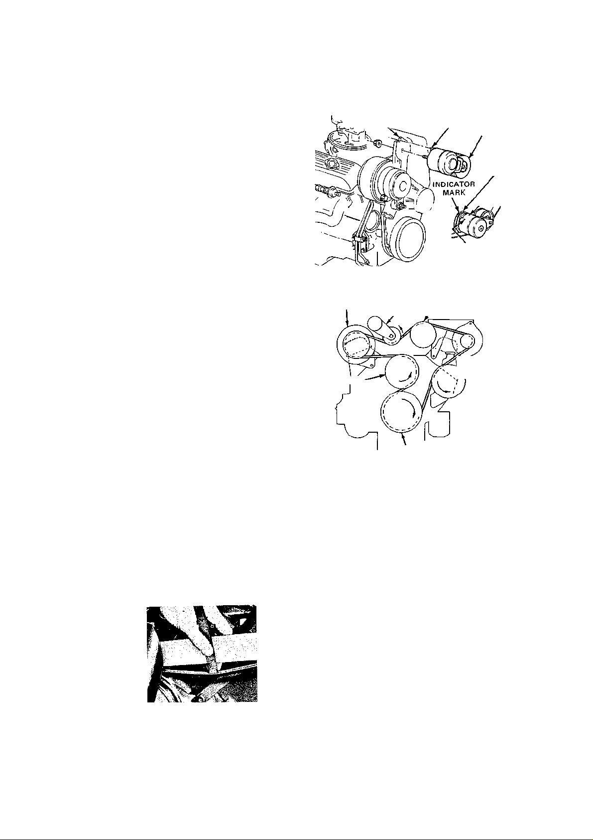
On all 1984 and later engines, a single serpentine belt is used to drive all accessories
formerly driven with V-belts. Belt tension is
maintained by a spring loaded tensioner which
has the ability to maintain belt tension over a
broad range of belt lengths. There is an indicator to make sure the tensioner is adjusted
to within its operating range. The belt tension is adjusted with a Vz inch breaker bar
inserted into the square hole in the tensioner
arm and a belt tension gauge (BT 7825 or
equivalent) to 120—140 Ibs, as read on the
Measuring fan belt tension
LOCATING SLOT
=. A/C COMPRESSOR
^ BRACKET
Serpentine drive belt tensioner—1984 and later
CRANKSHAFT
TENSIONER / GENERATOR
Serpentine drive belt installation
LOCATING TAB
OPERATING RANGE
„,-.„
TENSIONER
BRACKET
POWER
STEERING i \
tension gauge installed between the alternator and the A.I.R. pump.
Cooling System
CAUTION: Do not perform any coolant
system services on a hot engine.
At least once every 2 years, the engine
cooling system should be inspected, flushed,
and refilled with fresh coolant. If the coolant
is left in the system too long, it loses its ability to prevent rust and corrosion. If the coolant has too much water, it won't protect
against freezing.
The pressure cap should be looked at for
signs of age or deterioration. Fan belt and
other drive belts should be inspected and adjusted to the proper tension. (See checking
belt tension).
Hose clamps should be tightened, and soft
or cracked hoses replaced. Damp spots, or
accumulations of rust or dye near hoses, water
Page 22

18 GENERAL INFORMATION AND MAINTENANCE
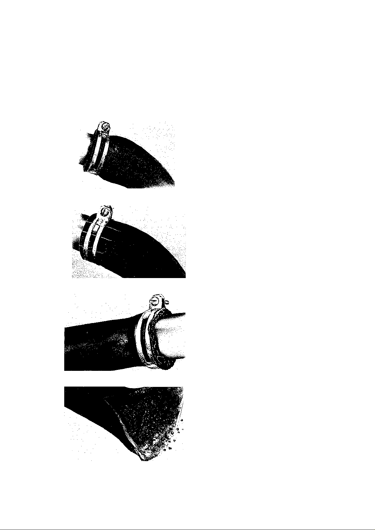
HOW TO SPOT WORN V-BELTS
V-Belts are vital to efficient engine operation—they drive the fan, water pump and other accessories. They require little maintenance (occasional tightening) but they will not last forever.
Slipping or failure of the V-belt will lead to overheating. If your V-belt looks like any of these, it
should be replaced.
This belt has deep cracks, which cause it to flex.
Too much flexing leads to heat build-up and
premature failure. These cracks can be caused
by using the belt on a pulley that is too small.
Notched belts are available for small diameter
pulleys.
Cracking or weathering
Oil and grease on a belt can cause the belt's
rubber compounds to soften and separate
from the reinforcing cords that hold the belt
together. The belt will first slip, then finally
fail altogether.
Softening (grease and oil)
Glazing
Worn cover
Glazing is caused by a belt that is slipping. A
slipping belt can cause a run-down battery,
erratic power steering, overheating or poor
accessory performance. The more the belt
slips, the more glazing will be built up on the
surface of the belt. The more the belt is
glazed, die more it will slip. If the glazing is
light, tighten the belt.
The cover of this belt is worn off and is peeling away. The reinforcing cords will begin to
wear and the belt will shortly break. When
the belt cover wears in spots or has a rough
jagged appearance, check the pulley grooves
for roughness.
This belt is on the verge of breaking and leaving you stranded. The layers of the belt are
separating and the reinforcing cords are exposed. It's just a matter of time before it
breaks completely.
Separation
Page 23
GENERAL INFORMATION AND MAINTENANCE 19
HOW TO SPOT BAD HOSES
Both the upper and lower radiator hoses are called upon to perform difficult jobs in an inhospitable environment. They are subject to nearly 18 psi at under hood temperatures often over
280°F., and must circulate nearly 7500 gallons of coolant an hour—3 good reasons to have good
hoses.
A good test for any hose is to feel it for soft or
spongy spots. Frequently these will appear
as swollen areas of the hose. The most likely
cause is oil soaking. This hose could burst at
any time, when hot or under pressure.
Swollen hose
Cracked hoses can usually be seen but feel
the hoses to be sure they have not hardened;
a prime cause of cracking. This hose has
cracked down to the reinforcing cords and
could split at any of the cracks.
Cracked hose
Frayed hose end (due to weak clamp)
Weakened clamps frequently are the cause of
hose and cooling system failure. The connection between the pipe and hose has deteriorated enough to allow coolant to escape when
the engine is hot.
Debris, rust and scale in the cooling system
can cause the inside of a hose to weaken. This
can usually be felt on the outside of the hose
as soft or thinner areas.
Debris In cooling system
Page 24
20 GENERAL INFORMATION AND MAINTENANCE
C
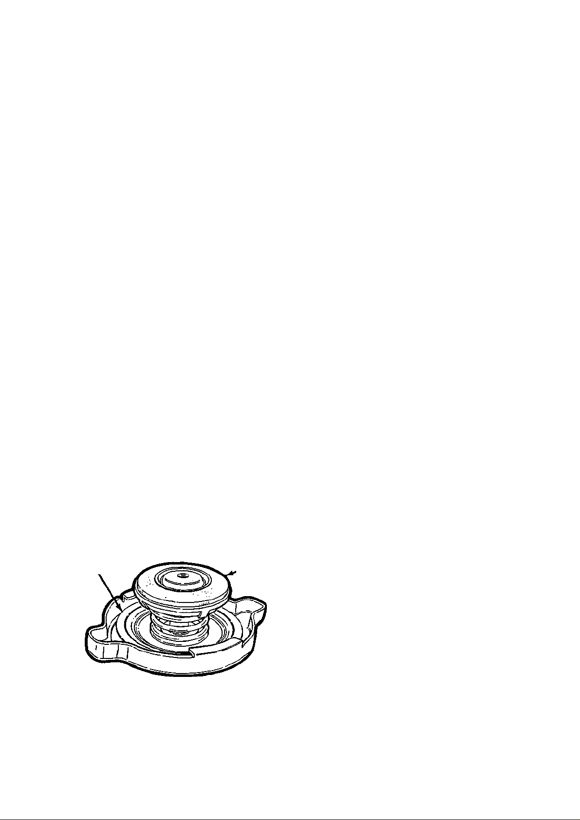
heck the radiator cap's rubber gasket and metal
pump or other areas, indicate possible leakage, which must be corrected before filling
die system with fresh coolant.
CHECK THE RADIATOR CAP
While you are checking me coolant level, also
check the condition of the radiator cap gasket
and the seal inside of the cap (if your vehicle
uses a coolant recovery system). The radiator
cap is designed to seal the cooling system under normal operating conditions which allows
the system to build-up a certain amount of
pressure (this pressure rating is stamped or
printed on the cap). The pressure in the system raises the boiling point of the coolant to
help prevent overheating. If the radiator cap
does not seal, the boiling point of the coolant
is lowered and overheating will occur. If the
cap must be replaced, purchase the new cap
according to the type of system you have (with
or without a coolant recovery tank) and the
pressure rating which is specified for your vehicle.
CLEAN RADIATOR OF DEBRIS
Periodically clean any debris—leaves, paper,
insects, etc.—from the radiator fins. Pick the
large pieces off by hand. The smaller pieces
can be washed away with water pressure from
a hose.
Carefully straighten any bent radiator fins
with a pair of needle nose pliers. Be careful—
the fins are very soft. Don't wiggle the fins
back and forth too much. Straighten them
once and try not to move them again.
DRAIN AND REFILL THE COOLING
SYSTEM
Completely draining and refilling the cooling
system every two years at least will remove
accumulated rust, scale and other deposits.
Coolant in late model cars is a 50-50 mixture
of ethylene glycol and water for year round
SEAL
seal for deterioration at least once a year
GASKET
use. Use a good quality antifreeze with water
pump lubricants, rust inhibitors and other
corrosion inhibitors along with acid neutralizers.
1. Drain the existing antifreeze and cool
ant. Open the radiator and engine drain petcocks, or disconnect die bottom radiator hose,
at the radiator outlet.
NOTE: Before opening the radiator pet-
cock, spray it with some penetrating lubricant.
2. Close the petcock or re-connect the
lower hose and fill the system with water.
3. Add a can of quality radiator flush.
4. Idle the engine until the upper radia
tor hose gets hot.
5. Drain the system again.
6. Repeat this process until the drained
water is clear and free of scale.
7. Close all petcocks and connect all the
hoses.
8. If equipped widi a coolant recovery
system, flush die reservoir witii water and
leave empty.
9. Determine die capacity of your cool
ing system (see capacities specifications). Add
a 50/50 mix of quality antifreeze (ethylene
glycol) and water to provide die desired pro
tection.
10. Run die engine to operating tempera
ture.
11. Stop die engine and check die coolant
level.
12. Check die level of protection with an
anti-freeze tester, replace die cap and check
for leaks.
Air Conditioning
SAFETY PRECAUTIONS
There are two particular hazards associated
widi air conditioning systems and diey bodi
relate to die refrigerant gas.
First, die refrigerant gas is an extremely
cold substance. When exposed to air, it will
instantly freeze any surface it comes in contact widi, including your eyes. The odier
hazard relates to fire. Ahhough normally nontoxic, refrigerant gas becomes highly poisonous in die presence of an open flame. Inhalation of die vapor formed by burning refrigerant can be fetal. Keep all forms of fire
(including cigarettes) well clear of die airconditioning system.
Any repair work to an air conditioning system should be left to a professional. Do not,
under any circumstances, attempt to loosen
Page 25

GENERAL INFORMATION AND MAINTENANCE 21
or tighten any fittings or perform any work
other than that outlined here.
CHECKING FOR OIL LEAKS
Refrigerant leaks show up as oily areas on the
various components because the compressor
oil is transported around the entire system
along with the refrigerant. Look for oily spots
on all the hoses and lines, and especially on
the hose and tubing connections. If there are
oily deposits, the system may have a leak, and
you should have it checked by a qualified repairman.
NOTE: A small area of oil on the front of
the compressor is normal and no cause for
alarm.
CHECK THE COMPRESSOR BELT
Refer to the section in this chapter on "Drive
Belts."
KEEP THE CONDENSER CLEAR
Periodically inspect the front of the condenser for bent fins or foreign material (dirt,
buts, leaves, etc.) If any cooling fins are bent,
straighten them carefully with needlenosed
pliers. You can remove any debris with a stiff
bristle brush or hose.
OPERATE THE AIC SYSTEM
PERIODICALLY
A lot of A/C problems can be avoided by simply running the air conditioner at least once
a week, regardless of the season. Simply let
the system run for at least 5 minutes a week
(even in the winter), and you'll keep the internal parts lubricated as well as preventing
the hoses from hardening.
REFRIGERANT LEVEL CHECK
There are two ways to check refrigerant level,
depending on how your model is equipped.
With Sight Glass
The first order of business when checking the
sight glass is to find the sight glass. It will
either be in the head of the receiver/drier, or
in one of the metal lines leading from the top
of the receiver/drier. Once you've found it,
wipe it clean and proceed as follows:
1. With the engine and the air conditioning system running, look for the flow of refrigerant through the sight glass. If the air
conditioner is working properly, you'll be able
to see a continuous flow of clear refrigerant
through the sight glass, with perhaps an occasional bubble at very high temperatures.
Air conditioning sight glass
2. Cycle the air conditioner on and off to
make sure what you are seeing is clear refrig
erant. Since the refrigerant is clear, it is pos
sible to mistake a completely discharged sys
tem for one that is fully charged. Turn the
system off and watch the sight glass. If there
is refrigerant in the system, you'll see bub
bles during the off cycle. If you observe no
bubbles when the system is running, and the
air flow from the unit in the car is delivering
cold air, everything is OK.
3. If you observe bubbles in the sight glass
while the system is operating, the system is
low on refrigerant. Have it checked by a
professional.
4. Oil streaks in the sight glass are an in
dication of trouble. Most of the time, if you
see oil in the sight glass, it will appear as a
series of streaks, although occasionally it may
be a solid stream of oil. In either case, it
means that part of the charge has been lost.
Without Sight Glass
On vehicles that are not equipped with sight
glasses, it is necessary to feel the temperature difference in the inlet and outlet lines at
the receiver/drier to gauge the refrigerant
level. Use the following procedure:
1. Locate the receiver/drier. It will gen
erally be up front near the condenser. It is
shaped like a small fire extinguisher and will
always have two lines connected to it. One
line goes to the expansion valve and the other
goes to the condenser.
2. With the engine and the air conditioner
running, hold a line in each hand and gauge
their relative temperatures. If they are both
the same approximate temperature, the sys
tem is correctly charged.
3. If the line from the expansion valve to
the receiver/drier is a lot colder than the line
from the receiver/drier to the condenser, then
the system is overcharged. It should be noted
that this is an extremely rare condition.
Page 26

22 GENERAL INFORMATION AND MAINTENANCE
4. If the line that leads from the re
ceiver/drier to the condenser is a lot colder
than the other line, the system is under
charged.
5. If the system is undercharged or over
charged, have it checked by a professional air
conditioning mechanic.
Windshield Wipers
Intense heat from the sun, snow and ice, road
oils and the chemicals used in windshield
washer solvents combine to deteriorate the
rubber wiper refills. The refills should be replaced about twice a year or whenever the
blades begin to streak or chatter.
WIPER REFILL REPLACEMENT
Normally, if the wipers are not cleaning the
windshield properly, only the refill has to be
replaced. The blade and arm usually require
replacement only in the event of damage. It
is not necessary (except on new Tridon refills)
to remove the arm or the blade to replace the
refill (rubber part), though you may have to
position the arm higher on the glass. You can
do this turning the ignition switch on and operating the wipers. When they are positioned
where they are accessible, turn the ignition
switch off.
There are several types of refills available
and your vehicle could have any kind, since
aftermarket blades do not necessarily use the
same refill as original equipment blades. The
two most popular original equipment types
are what we refer to .as the first and the third
types. The remaining styles are used mainly
as aftermarket replacements.
The first type of blade uses a release button that is pushed down to allow the refill to
slide out of the yoke jaws. The new refill slides
in and locks in place.
The second type of refill is removed by lo-
cating where the metal backing strip (or where
the refill) is wider and inserting a small
screwdriver between the frame and the metal
backing strip. Press down to release the refill
from the retaining tab.
The third type of refill is replaced by
squeezing the two metal tabs located at the
end of the refill and sliding the refill out of
the frame jaws. When the new refill is installed, the tabs will click into place and lock
the refill.
The fourth type of refill is termed the "polycarbonate type." The refill of this type is held
into place by a locking lever which is pushed
downward out of the groove in the arm to free
the refill. The new refill will lock into place
automatically as it is installed.
The fifth type of refill is used with the Tridon blade. The Tridon refill has a plastic
backing strip with a notch about an inch from
the end. Hold the blade (frame) on a hard
surface so that it is tightly bowed. Grip the
tip of the backing strip and pull upward while
twisting counterclockwise. The backing strip
will snap out of the retaining tab. Do this for
the remaining tabs until the refill is free of
the arm. The refills must be replaced with
identical new refills.
No matter what type of refill is used, be
sure that all of the frame claws engage the
refill. Before operating the wipers, be sure
that no part of the metal frame contacts the
windshield glass.
Fluid Level Checks
ENGINE OIL
The engine oil level is checked with the dipstick, which is located either on the left side
of the engine (small-blocks) or the right side
of the engine (big-blocks).
NOTE: The oil should be checked before
the engine is started or five minutes after
the engine has been shut off. This gives the
oil time to drain back to the oil pan and
prevents an inaccurate oil level reading.
Remove the dipstick from its tube, wipe it
clean, and insert it back into the tube. Remove it again and observe the oil level. It
should be maintained between the "full" and
"add" marks without going above "full" or
CAUTION: Do not overfiU the crankcase.
It may result in oil-fouled spark plugs, oil
leaks caused by oil seal failure, or engine
damage due to foaming of the oil.
MANUAL TRANSMISSION FLUID
Remove the filler plug from the side of the
transmission (the upper plug if the transmission has two plugs). The oil should be level
with the bottom edge of the filler hole. This
should be checked at least once every 6,000
miles and more often if any leakage or seepage is observed. Fill with SAE 80 or 90 multipurpose gear lubricant.
NOTE: The 4 speed overdrive transmis-
sion uses two types of fluid. See "Lubrication" for details.
below "add."
Page 27
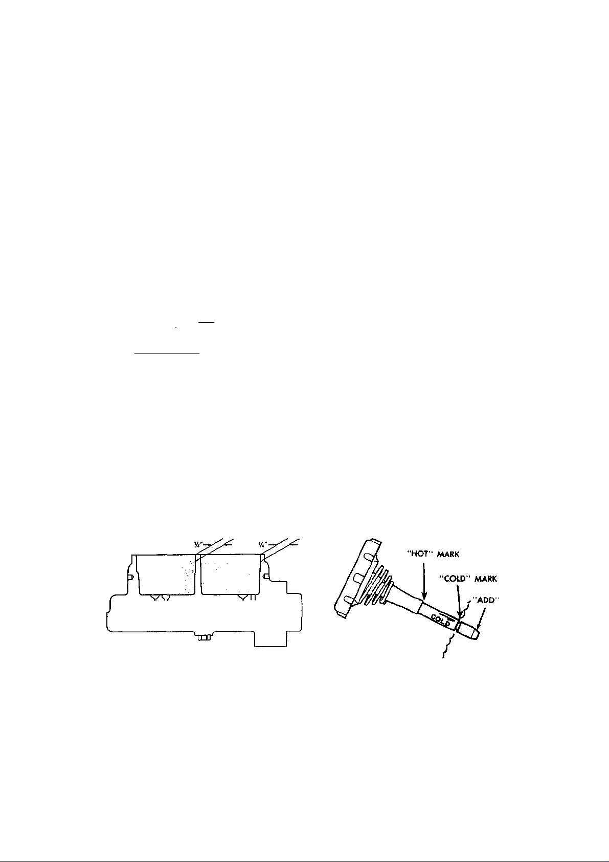
GENERAL INFORMATION AND MAINTENANCE 23
AUTOMATIC TRANSMISSION FLUID
Run the engine until it reaches normal operating temperature. Park the car on a level
surface. With the transmission in Park and
the engine idling, the fluid level on the dipstick should be between the "foil" mark and
Vt inch below "foil" mark. Repkce the dipstick making sure that it is pushed folly into
the filler tube.
CAUTION: Do not overfill the automatic
transmission. Use Dexron® or Type A automatic transmission fluid or any other
equivalent fluid. One pint raises the level
from' 'add'to"full"
(65 -85'F.) (18 -29 C.)
COOL HOT
ADD 1 PT.—J ° <,
I
NOTE: DO NOT OVERf ILL. It
takes only one pint to raise level from ADD to FULL
with a hot transmission.
Automatic transmission dipstick
i—FULL HOT
BRAKE MASTER CYLINDER
Once every 6,000 miles or four months, check
the brake fluid level in the master cylinder.
The master cylinder is mounted on the firewall and is divided into two reservoirs and
the fluid level in each reservoir must be
maintained at V4 inch below the top edge. Use
only heavy-duty brake fluid (DOT 3 or 4),
which is recommended for disc brake applications. See "Brakes" for details.
neck, or the line on expansion tank-equipped
models.
CAUTION: Allow the engine to cool con-
siderably and then add water while the engine is running.
STANDARD REAR AXLE
The rear axle oil level should be checked
when the chassis is lubricated. Remove the
plug from the side of the housing. The lubricant level should be maintained at the bottom of the filler plug hole. When repkcing
oil, use SAE 80 or 90 multipurpose hypoid
gear lubricant.
POSITRACTION REAR AXLE
Lubricant level should be checked at each
chassis lubrication and maintained at the bot-
tom of the filler plug hole. Special Positrac-
tion oil must be used in this differential.
CAUTION: Never use standard differential
lubricant in a Positractton differential.
MANUAL STEERING GEAR
Check the lubricant by removing the center
bolt on the side cover of the steering gear.
Grease must be up to the level of this bolt
hole.
POWER STEERING RESERVOIR
Maintain the proper fluid level as indicated
on the cap of the reservoir. Check this level
with the engine off and warm. Use GM power
steering fluid or its equivalent. Note: Avoid
using automatic transmission fluid in power
steering units except in an emergency.
Checking the master cylinder fluid level
LEVEL CYLINDER
Power steering dipstick
COOLANT
Check the coolant level when the engine is
cold. The level of coolant should be maintained 2 in. below the bottom of the filler
Tires
INFLATION PRESSURE
Tire inflation is the most ignored item of auto
maintenance. Gasoline mileage can drop as
Page 28

24 GENERAL INFORMATION AND MAINTENANCE
454
350
IF
4.0
4.0
8©
Year
1963
1964
1965
1966
1967
1968
1969
1970
1971
Engine
Model (cu
In.) ©
327 (hyd.
Crankcase
Add 101 for
New Filter
4
lifters)
327 HP (solid
5
lifters)
327 (hyd.
4
lifters)
327 HP (solid
5
lifters)
327 (hyd.
4
lifters)
327 (solid
5
lifters)
327 (300
4
hp)
327 HP
5
(350 hp)
427 5
327 (300
hp)
327 HP
(350 hp)
4
5
427 5
427 HP
327 (300
hp)
327 HP
(350 hp)
5
4
4
427 5
427 HP
350 (all)
5
4
427 5
427 HP
350 (all)
454 (all)
350 (270
hp)
350 HP
(330 hp)
5
4
5
4
4
454 5
454 HP
5
Capacities & Pressure
Transmission Pts to Refill
after Draining
Manual
3-spd 4-spd
2 2.5
— 2.5
2 2.5
— 2.5
2 2.5
2 2.5
3 3.0
— 3.0
— 3.0
3 3.0
— 3.0
— 3.0
— 3.0
3 3.0
— 3.0
— 3.0
— 3.0
— 3.0
— 3.0
— 3.0
— 3.0
— 3.0
— 3.0
— 3.0
— 3.0
— 3.0
Automatic
18 3.7 20 17 13
— 3.7 20 17 13
18 3.7 20 17 13
— 3.7 20 17 13
18 3.7 20 17 13
18 3.7 20 17 13
18 3.7 20 19 15
— 3.7 20 19 15
— 3.7 20 22 15
19 3.7 20 19 15
— 3.7 20 19 15
19 3.7 20 22 15
— 3.7 20 22 15
22 3.7 20 15 15
— 3.7 20 15 15
22 3.7 20 22 15
— 3.7 20 22 15
8® 4.0 20 15 15
8© 4.0 20 22 15
8© 4.0 20 22 15
8® 4.0 20 ® 15
22 4.0 20 22 15
22 4.0 18 15 15
— 4.0 18 18 15
22 4.0 18 22 15
22 4.0 18 20 15
(pts)
Fuel
Tank
(gai)
Cooling
System
(qts)
Max
Coolant
Pressure
(psi)
1972 350 (all)
4
— 3.0
22
22
22 4.0 18 ® 15
Page 29

1973
15
18
454 8© 18 24 15 4.0
— 3.0
— 3.0
Is"
Page 30
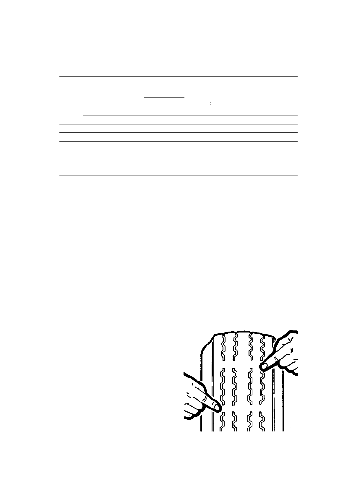
GENERAL INFORMATION AND MAINTENANCE 25
1984®
20 15 15
Model
Year
1974
1975-76
350 4
1977
350 4
1978
350 4
1979
1980
1981
350 4
1982
350 4
® "HP" denotes high performance engine; "hp" denotes horsepower
© For pan removal and filter change only
© 15 qts. for standard engine, 18 qts. with special high performance (L82) engine
® With automatic transmission and air conditioning add 1 qt.
© With optional close-ratio transmission, subtract 1A qt.
® See "Manual Transmission" for details on 4 speed overdrive
(cuin.)©
350 4
454 5
350.
4
305, 350
4
—
350
Capacities & Pressure (cont.)
Transmission Pis to Refill
Engine
Crankcase
Add 1 at far
New Filler
3-spd 4 -spd
— 3.0
— 3.0
— 3.0
— 3.0
— 3.0
— 3.0®
— 3.0®
— 3.0®
— —
4.0
after Draining
Manual
Automatic
8® 4.0 18 17 17
8® 4.0 18 22 23
8© 4.0 18 17 17
8©
6©
6©
6® 4.0 24 21® 15
6® 4.0 24 21® 15
10© 4.0 24 21® 15
10®
Fuel
Tank
(gal)
(pts)
3.75
17 21 15
3.75
24
3.75
24
4.0
Cooling
System
(qts)
21.6
15
21.6
15
Max
Coolant
Pressure
(psl)
much as .8% for every 1 pound per square
inch (psi) of under inflation.
Two items should be a permanent fixture
in every glove compartment; a tire pressure
gauge and a tread depth gauge. Check the
tire air pressure (including the spare) regularly with a pocket type gauge. Kicking the
tires won't tell you a thing, and the gauge on
the service station air hose is notoriously inaccurate.
The tire pressures recommended for your
car are usually found on the glove-box door
or in the owner's manual. Ideally, inflation
pressure should be checked when the tires
are cool. When the air becomes heated it expands and the pressure increases. Every 10°
rise (or drop) in temperature means a difference of 1 psi, which also explains why the tire
appears to lose air on a very cold night. When
it is impossible to check the tires "cold," allow for pressure build-up due to heat. If the
"hot" pressure exceeds the "cold" pressure
by more than 15 psi, reduce, your speed, load
or both. Otherwise internal heat is created in
the tire. When the heat approaches the temperature at which the tire was cured, during
manufacture, the tread can separate from the
body.
CAUTION: Never counteract excessive
pressure build-up by bleeding affair pressure (letting some air out.) This will only
further raise the tire operating temperature.
Before starting a long trip with lots of luggage, you can add about 2—4 psi to the tires
to make them run cooler, but never exceed
the maximum inflation pressure oil the side
of the tire.
TREAD DEPTH
All tires made since 1968, have 8 built-in tread
wear indicator bars that show up at W wide
smooth bands across the tire when Vie" of
Tread wear Indicators will appear when the tire Is
worn out
Page 31
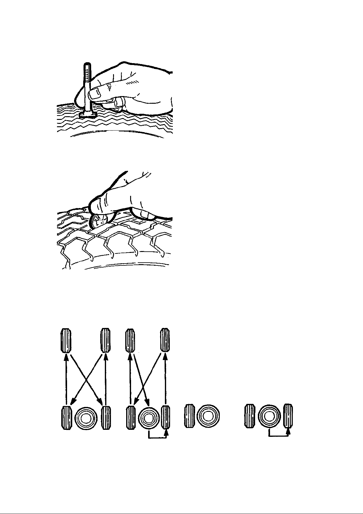
26 GENERAL INFORMATION AND MAINTENANCE
tread remains. The appearance of tread wear
indicators means that the tires should be replaced. In feet, many states have laws prohibiting the use of tires with less than Vie" tread.
You can check your own tread depth with an
inexpensive gauge or by using a Lincoln
head penny. Slip the Lincoln penny into several tread grooves. If you can see the top of
Lincoln's head in 2 adjacent grooves, the tires
have less than Vie" tread left and should be
replaced. You can measure snow tires in the
same manner by using the "tails" side of the
Tread depth can be checked with an Inexpensive
gauge
A penny works as weli as anything for checking
tread depth; If the top of Lincoln's head Is vlsable
In two or more adjacent grooves, the tires should
be replaced
Lincoln penny. If you can see the top of the
Lincoln memorial, it's time to replace the
snow tires.
TIRE ROTATION
Tire wear can be equalized by switching the
position of the tires about every 6000 miles.
Including a conventional spare in the rotation
pattern can give up to 20% more tire life.
CAUTION: Do not include the new "Space-
Saver®' or temporary spare tires in the rotation pattern.
There are certain exceptions to tire rotation, however. Studded snow tires should not
be rotated, and radials should be kept on the
same side of the car (maintain the same direction of rotation). The belts on radial tires get
set in a pattern. If the direction of rotation is
reversed, it can cause rough ride and vibration.
NOTE: When radials or studded snows are
taken off the car, mark them, so you can
maintain the same direction of rotation.
BIAS PLY TIRE 4-
WHEEL ROTATION
BIAS PLY TIRE S-
WHEEL ROTATION
Tire rotation diagrams; note that radlals should not be cross-switched
RADIAL PLY TIRES
4-WHEEL ROTATION
RADIAL PLY TIRES
5-WHEEL ROTATION
Page 32
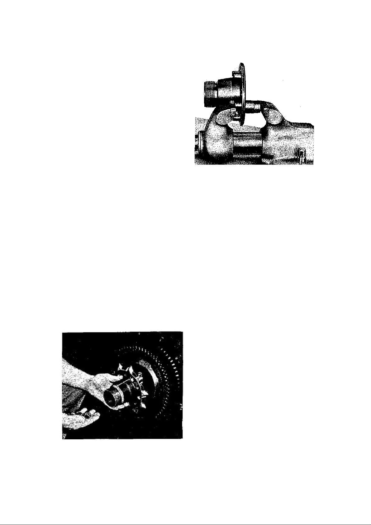
GENERAL INFORMATION AND MAINTENANCE 27
TIRE STORAGE
Store the tires at proper inflation pressures if
they are mounted on wheels. All tires should
be kept in a cool, dry place. If they are stored
in the garage or basement, do not let them
stand on a concrete floor; set them on strips
of wood.
ALUMINUM WHEELS
CAUTION: If your vehicle has aluminum
wheels, whether they are the early "turbine" style or the late (76 and up) slotted
style, be VERY careful when using any type
of cleaner on either the wheels or the tires.
Read the label on the package of the cleaner
to make sure that it will not damage aluminum.
An optional knock-off wheel was introduced with the 1963 Stingray. This wheel option consisted of 15 x 6L cast aluminum
wheels, knock-off locking nuts, and wheel
adapters. The latter bolt to the hub, using the
existing wheel hub bolts. The flange of the
adapter had five pins that fitted into corresponding holes in the optional wheels and located the wheel to the hub. The securing device was the single, center, knock-off nut.
Each Corvette delivered with the optional,
knock-off aluminum wheels, was equipped
with a special knock-off hammer. Owners of
these cars were urged to tighten the knockoff nut every 100 miles for the first 500 miles.
The suggested method was to strike the ears
of the nut eight hard blows.
Should adapter pin replacement become
necessary, remove the wheel and tire assembly and remove the adapter from the wheel
hub. Select a socket of suitable size that will
Knock-off wheel adapter
Removing adapter pin
slip over the adapter pin. Position the socket
over the back of the pin and clamp the entire
assembly in a vise so that the socket acts as a
spacer to receive the damaged pin. Tighten
the vise and press the pin from the adapter.
Position the replacement pin and start it into
the hole by tapping lightly. Position the
spacer socket on the opposite side and again
clamp the assembly in the vise. Press the replacement pin into the adapter. Check to see
that it seats firmly against its bore. Install the
adapter and wheel.
NOTE: The optional 16 in. cast aluminum
wheels on 1984 models are designated for
right, left, front or rear installation depending on the cooling fins. Rear wheels
are one inch wider than the front.
Fuel Filter
The filter in Carter WCFB, Rochester Quadrajet, Holley 2300, and Holley 4150 carburetors is located in the fuel inlet connection
and should be replaced at least every 12,000
miles or sooner if engine flooding occurs. The
Carter AFB uses an in-line filter, which
should be replaced every 24,000 miles. The
Rochester and Throttle Body fuel injection
uses an in-line filter, which should be replaced every 15,000 miles.
To replace an in-line filter, disconnect the
fitting at each end of the filter canister, discard the old filter, and install the replacement in the reverse order of removal.
To replace a fuel inlet filter:
1. Using an open-end wrench (preferably
a line wrench), disconnect the fuel line con
nection from the larger fuel filter nut.
2. Remove the larger nut from the carbu
retor.
Page 33
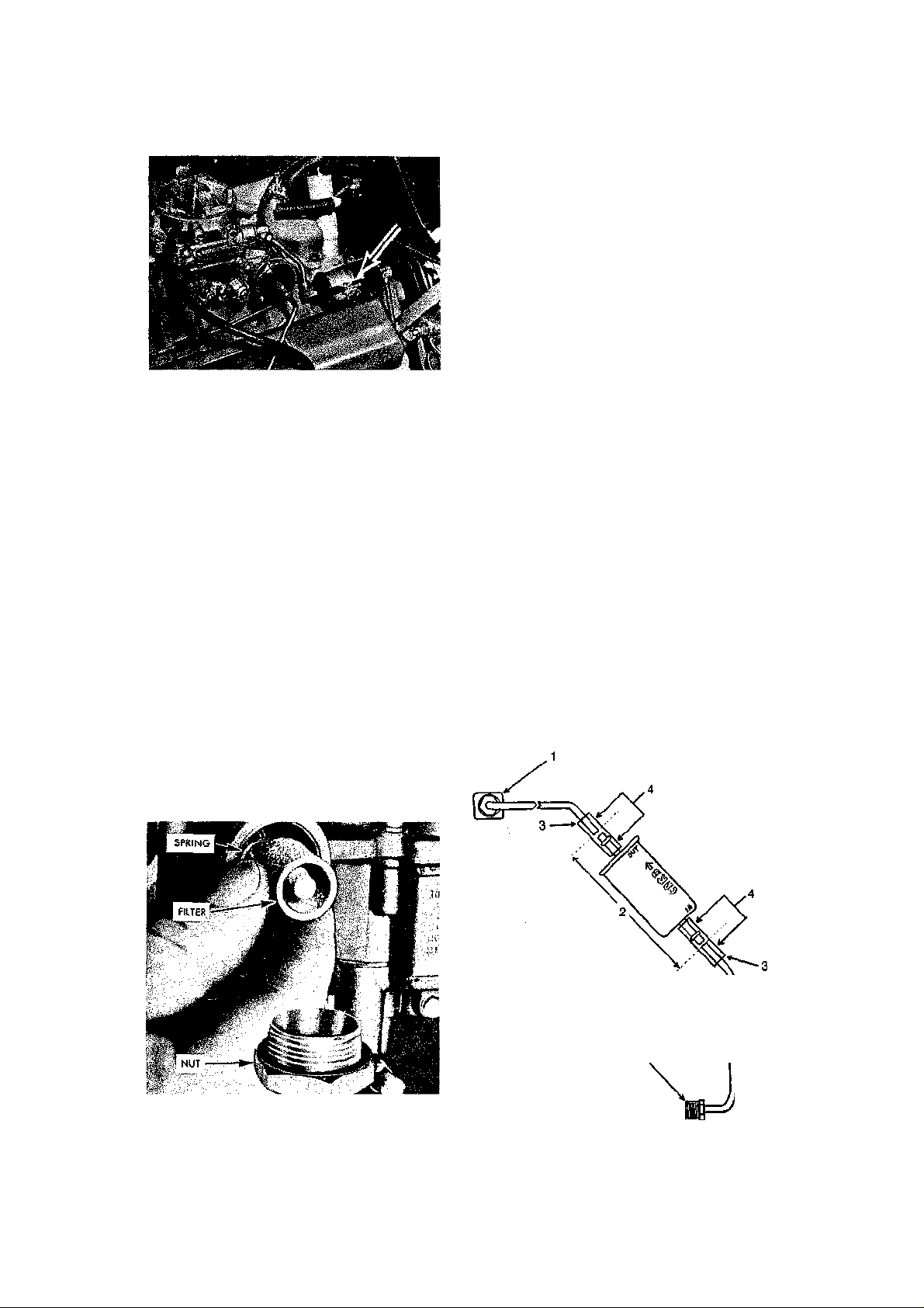
28 GENERAL INFORMATION AND MAINTENANCE
Most late models have this bronze fuel filter lo
-
rolet recommends doing this for vehicles
which see severe usage (racing, etc.), it is also
a wise move for street-driven vehicles. The
small, carburetor mounted filter clogs more
easily than a large in-line filter. The clogged
filter can cause a drastic drop in fuel pressure
which will generally cause the engine to run
leaner; engine damage can result from an excessively lean fuel mixture. Another negative
view of a carburetor mounted filter is that if
a fuel pressure problem is encountered, a
clogged carburetor mounted filter would not
show a pressure loss during a fuel pressure
Inline fuel filter
3. Remove the filter element and spring
from the carburetor.
4. Check the bronze element for dirt
blockage by blowing on the cone end. If the
element is good, air should pass through eas-
fly.
5. If the car has a paper element instead
of a bronze element, check by blowing into
the fuel inlet end. If air does not pass through
easily replace the element. Do not attempt
to clean these elements.
6. Install the spring and then the element
into the carburetor, making sure that the
small end of the bronze cone is facing out
ward.
7. Install a new gasket on the large nut and
tighten securely.
8. Insert the fuel line and tighten the nut
with a line wrench.
If your vehicle is equipped with a small filter mounted in die carburetor fuel inlet, it
may be wise to consider replacing this filter
with a larger "in-line" filter. Although Chev-
test since the filter is mounted after the fuel
pressure test connection. In-line fuel filters
are relatively inexpensive and easy to install.
The added filtering protection and longer filter life offered by the in-line filter more than
make up for its slight additional cost.
NOTE: Do not perform this operation on
1976 and later models, as special fuel filters
with anti-spillage valves are used. If you
decide to install an in-line fuel filter, first
remove and discard the carburetor mounted
filter. Position the in-line fuel filter against
the fuel line to judge where the fuel line has
to be cut. Do not mount the in-line filter
straight up as this could allow fuel vapors to
block the filter outlet (vapor-lock).
Preferably, the filter should be mounted on a
45° angle and be positioned an inch away from
surrounding engine components. Mark where
the fuel line must be cut, disconnect the line
from the fuel pump and remove the fuel line.
Using either a "mini" tubing cutter or a hack-
cated behind the fuel fitting
1. Carburetor fitting
2. Cut fuel line here
3. Fuel-resistant connecting hoses
4. Install clamps here
5. Fuel pump fitting
5
Typical in-line fuel filter installation
Page 34

Maintenance
1963-67
Maintenance Intervals
1968- 71
1972-74 1975-79
1980-84
bath Paper elem ent ©
PCV Valve (Replace) 12 mo/1 2,000 mi 12 mo/1 2,000 mi 12 mo/1 2,000 mi 15,000 mi
12,000 mi 1 2,000 mi
(replace)
—
Replace filter
Check
Replace
Engine Oil Filter (Replace) every oil change every oil change every oil change every oil change every oil change
Replace 12,000 mi 12,000 mi 12,000 mi 15,000 mi 15,000 mi.
Check Replace
Each fuel stop 4
mo/6,000 mi
6,000 mi
24,000 mi
12,000 mi (replace) 24,000 mi (replace) 30,000 mi (replace)
12 mo/1 2,000 mi.
(1970-71)
each fuel stop 4
mo/6,000 mi
6,000 mi
24,000 mi
12 mo/1 2,000 mi 24 mo/30,000 mi 24 mo/30,000 mi.
each fuel stop 4
mo/6,000 mi
each fuel stop 6
mo/7,500 mi
— — —
30,000 mi (replace)
30,000 mi.
each fuel stop 12
mo/7500 mi.®
—
Turbo Hydra-Matic Fluid
& Filter Check fluid
Change fluid Replace
Check lubricant Add
lubricant
Battery Lubricate terminal
felt washer Clean
terminals Check
electrolyte level
Coolant level Each fuel stop each fuel stop each fuel stop each fuel stop each fuel stop
6,000 mi as
necessary
6,000©
6,000 mi Twice
monthly
6,000 mi
24,000 mi
24,000 mi
6,000 mi as
necessary
6,000©
6,000 mi twice
monthly
6,000 mi
24,000 mi
24,000 mi
6,000 mi as
necessary
as necessary
twice monthly
6,000 mi
30,000 mi
30,000 mi
7,500 mi as
necessary
as necessary
twice monthly ®
each eng. oil
change
100,000 mi.®
100,000 mi.®
7500 mi. as
necessary
as necessary
not necessary
O
m
z m
DO
O
30
1
> o
z m
o m
<O
Lubricate 24,000 mi 24,000 mi 24,000 mi 30,000 mi 30,000 mi
l Bearings
Page 35

30 GENERAL INFORMATION AND MAINTENANCE
§
i
(0
8
(0
1
E
1
E
to
CO
" c (fl
g>0) 0) §
•5 "5
CO m
E
,§•
E
O C
8
O
to
E
Cu (A
- c 10
C3
-s
S
P
1
E
_g 'cr
* 1 -
Page 36

CM
E
8
in
1
O)
1 8
o
GENERAL INFORMATION AND MAINTENANCE 31
©
1 o
s
JD
o o o CD"
o o o
CO
E
o
o
o
co"
fCD ^
"I
in
ts
Page 37

32 GENERAL INFORMATION AND MAINTENANCE
40
50
40
50
30
20
saw with a fine-toothed blade, cut the fuel
line and make sure to clear the line of metal
particles left from the cutting. Reinstall the
line but do not yet tighten the fittings. Install
the in-line filter (if the filter is marked "in"
and "out," install the "out" side towards the
carburetor), fuel-resistant connecting hoses,
and the clamps. Tighten the hose clamps and
the fuel line fittings at the fuel pump and carburetor. Start the engine and check for leaks.
LUBRICATION
Oil and Fuel Recommendations
For 1980 and earlier vehicles, oils having one
of the following service ratings MUST be
used: SE, SE/CC, or SF. For 1981 and later
vehicles, use ONLY SF rated oils; it is O.K.
to use an SF oil with a combination rating,
such as SF/CC. Under the classification system developed by the American Petroleum
Institute, the SF rating designates the highest quality oil for use in passenger cars. In
view of this, it is recommended that you use
an SF rated oil an ANY Corvette. In addition, Chevrolet recommends the use of an
SF/Energy Conserving oil. Oils labeled "Energy Conserving (or Saving)," "Fuel (Gas or
Gasoline) Saving," etc. are recommended due
to their superior lubricating qualities (less
friction = easier engine operation) and fuel
saving characteristics. Pick your oil viscosity
with regard to the anticipated temperatures
during the period before your next oil change.
Using the accompanying chart, choose the oil
viscosity for the lowest expected temperature. You will be assured of easy cold starting
and sufficient engine protection.
NOTE: Some fuel additives contain chem-
icals that can damage the catalytic converter and/or oxygen sensor on late model
engines. Read all labels carefully before
using any additive in the engine or fuel system.
Fuel should be selected for the brand and
octane which performs best with your engine. Judge a gasoline by its ability to prevent "pinging," its engine starting capabilities (cold and hot), and general all-weather
performance. As far as octane rating is concerned, refer to the "General Engine Specifications" chart in Chapter 3 to find your engine and its compression ratio. If the
compression ratio is 9.0:1 or lower, in most
cases a regular grade of gasoline can be used.
Oil Viscosity Selection Chart
Multigrade
Singlegrade
Anticipated
Temperature Range
Above 32°F
May be used as low
as -10°F
Consistently below
10°F
Above 32°F
30
Temperature between
+32°Fand -10°F
SAE
Viscosity
10W-
10W20W20W-
10W-30
10W-
10W-40
5W5W-30
10W
If the compression ratio is 9.0:1-10.0:1, use a
premium grade of fuel. Vehicles with a
compression ratio higher than 10.0:1 (1970
and prior—check the engine chart) should use
a premium leaded fuel, if it is available. Most
oil companies have discontinued leaded pre-
mium gasoline; if you cannot find leaded premium, it has been recommended by several
enthusiast publications to mix regular leaded
and unleaded premium in a 1:3 proportion (1
part regular leaded to 3 parts unleaded premium). This mixture will give you the lubricating properties of lead and the added performance of a premium gasoline. Also, mixing
leaded and unleaded fuels will increase the
total octane rating by 1 or more points, de-
pending on the ratings of the gas which is ac-
tually used. DO NOT use straight unleaded
gas in a vehicle designed to use leaded; ex-
cessive valve and valve seat wear will result.
CAUTION: Unleaded fuel MUST be used
in 1975 and later vehicles equipped with
catalytic converters. Use of leaded fuel in
these vehicles will render the catalytic con-
verter ineffective and damage the oxygen
sensor, if equipped.
Fluid Changes
ENGINE OIL AND FILTER
The mileage figures given in your owner's
manual are the Chevrolet recommended intervals for oil and filter changes assuming average driving. If your Corvette is being used
under dusty, polluted, or off-road conditions,
change the oil and filter sooner than specified. The same thing goes for cars driven in
stop-and-go traffic or only for short distances.
Always drain the oil after the engine has
Page 38

GENERAL INFORMATION AND MAINTENANCE 33
been running long enough to bring it to operating temperature. Hot oil will flow easier
and more contaminants will be removed along
with the oil than if it were drained cold. You
will need a large capacity drain pan, which
you can purchase at any store which sells automotive parts. Another necessity is containers for the used oil. You will find that plastic
bottles, such as those used for bleach or fabric softener, make excellent storage jugs. One
ecologically desirable solution to the used oil
disposal problem is to find a cooperative gas
station owner who will allow you to dump
your used oil into his tank. Another is to keep
the oil for use around the house as a preservative on fences, railroad tie borders, etc.
Chevrolet recommends changing both the
oil and filter during the first oil change and
the filter every other oil change thereafter.
For the small price of an oil filter, it's cheap
insurance to replace the filter at every oil
change. One of the larger filter manufacturers points out in its advertisements that not
changing the filter leaves one quart of dirty
oil in the engine. This claim is true and should
be kept in mind when changing your oil.
CHANGING YOUR OIL
1. Run the engine until it reaches normal
operating temperature.
2. Jack up the front of the car and sup
port it on safety stands.
3. Slide a drain pan of at least 6 quarts
capacity under the oil pan.
4. Loosen the drain plug. Turn the plug
out by hand. By keeping an inward pressure
on the plug as you unscrew it, oil won't es
cape past the threads and you can remove it
without being burned by hot oil.
NOTE: Dispose of waste oil properly; don't
pollute the environment. Avoid prolonged
skin contact with used oil either directly or
from oil-saturated clothing.
5. Allow the oil to drain completely and
then install the drain plug. Don't overtighten
the plug, or you'll be buying a new pan or a
trick replacement plug for damaged threads.
6. Using a strap wrench, remove the oil
filter. Keep in mind that it's holding about
one quart of dirty, hot oil.
1963-67 Corvettes use a cartridge type oil
filter. On these models, loosen the center bolt
on the filter housing and remove the housing
along with the filter. If possible, replace the
housing-to-block seal during installation and
do not overtighten the housing bolt. Aftermarket adaptors are available to adapt the new
style spin-on filters to earlier engines. Some
prefer the convenience of a spin-on filter,
though the cartridge type filter actually offers
a greater filtering area.
7. Empty the old filter into the drain pan
and dispose of the filter.
8. Using a clean rag, wipe off the filter
adapter on the engine block. Be sure that the
rag doesn't leave any lint which could clog an
oil passage.
9. Coat the rubber gasket on the filter
with fresh oil. Spin it onto the engine by hand;
when the gasket touches the adapter surface
give it another Vz-% turn. No more, or you'll
squash the gasket and it will leak.
10. Refill the engine with the correct
amount of fresh oil. See the "Capacities"
chart.
11. Crank the engine over several times
and then start it. If the oil pressure gauge
shows zero, shut the engine down and find
out what's wrong.
12. If the oil pressure is OK and there are
no leaks, shut the engine off and lower the
car.
13. Wait a few minutes and check the oil
level. Add oil, as necessary, to bring the level
up to Full.
MANUAL TRANSMISSION
No intervals are specified for changing the
transmission lubricant, but after extended
heavy duty operation it may be a good idea.
The vehicle should be on a level surface and
the lubricant should be at operating temperature.
1. Position the vehicle on a level surface.
2. Place a pan of sufficient capacity under
the transmission drain plug.
3. Remove the upper (fill) plug to provide
a vent opening.
4. Remove the lower (drain) plug and let
the lubricant drain out.
5. Replace the drain plug.
6. Add lubricant with a suction gun or
squeeze bulb. The correct lubricant is SAE
80W-90 GL-5 Gear Lubricant, or SAE SOW
GL-5 for cold climates. Refer to the Capaci
ties and Pressures Chart for the correct quan
tity.
AUTOMATIC TRANSMISSION
NOTE: The fluid should be drained while
the transmission is warm.
1. Using a jack, raise the front of the ve-
hicle and support it safely with jackstands. If
the transmission pan has no drain plug, visu-
Page 39

34 GENERAL INFORMATION AND MAINTENANCE
ally check that you can gain access to all of
the transmission pan bolts. If you can, proceed to step 8; if not, proceed to step 2.
2. Place a jack under the transmission
with a block of wood (a piece of a 2x4 will do)
between the jack and the transmission pan.
3. Raise the jack until the wood block
contacts the transmission pan.
4. Remove the crossmember -to-transmission mount bolts and the crossmemberto-frame bolts.
5. Raise the transmission SLIGHTLY—
just enough to take the weight of the trans
mission off of the crossmember.
6. Turn the crossmember sideways and
remove it.
7. Place a jackstand close to the transmis
sion tailshaft. Lower the jack until the trans
mission rests on the stand. Remove the jack
and the wood block.
8. Place a drain pan under the transmis
sion pan. If the pan has a drain plug, remove
it and allow the fluid to drain.
9. If the pan does not have a drain plug,
remove the pan bolts from one side of the
pan and loosen the rest of the bolts. This will
allow the pan to partially drain. Remove the
remaining pan bolts and carefully lower the
pan away from the transmission.
NOTE: If the transmission fluid is dark or
has a burnt smell, transmission damage is
indicated. Have the transmission checked
professionally.
CAUTION: If the pan sticks, carefully tap
sideways on the pan with a rubber mallet
or a plastic hammer to break the pan loose.
DO NOT dent the pan. Avoid prying the
pan off with a screwdriver—this can bend
the pan or crack the transmission case.
10. Empty the pan, remove the gasket
material, and clean the pan with solvent (car
buretor cleaner works well).
11. Remove any gasket material which may
remain on the transmission case.
12. Remove the transmission filter from the
valve body. The filter may have either a fi
brous or screen filtering element and is re
tained by one or two fasteners.
13. Install a new filter using a new gasket
or O-ring (TH400's).
NOTE: If the transmission uses a filter
having a fully exposed screen, it may be
cleaned and re-used.
14. Install the pan using a new gasket.
Tighten the bolts to 12-14 ft. Ibs. in a criss
cross pattern. Recheck the bolt torque after
all of the bolts have been tightened once.
15. Add either Dexron or Dexron II trans
mission fluid through the filler tube. See the
Capacities Chart to determine the proper
amount of fluid to be added.
CAUTION: DO NOT OVERFILL the
transmission; foaming of the fluid and subsequent transmission damage due to slippage will result.
16. With the gearshift lever in PARK, start
die engine and let it idle. Do not race the
engine.
17. Move the gearshift lever through each
position, holding the brakes. Return the le
ver to PARK, and check the fluid level with
the engine idling. The level should be be
tween the two dimples on the dipstick, about
Vs. in. below the ADD mark. Add fluid, if
necessary.
18. Check the fluid level after the vehicle
has been driven enough to thoroughly warm
up the transmission. Details are given under
Fluid Level Checks earlier in the Chapter. If
the transmission is overfilled, the excess must
be drained off-
REAR AXLE
Refer to the Maintenance Intervals chart for
information on when to change the fluid.
1. Run the vehicle so the lubricant reaches
operating temperature.
2. Position a drain pan under the rear axle.
3. Remove the axle housing cover and gas
ket and drain the lubricant.
4. Clean the gasket sealing surfaces and
install the cover with a new gasket.
5. Torque the cover bolts in a crosswise
pattern to 20 ft. Ibs.
6. Add 4 oz. of rear axle lubricant additive
(GM 1052358).
7. Use a suction gun or a squeeze bulb and
refill the differential housing to a level within
%" of the filler plug with rear axle lubricant
(GM 1052271) or equivalent. (See the Capac
ities Chart),
8. Install the filler plug.
COOLANT
Refer to the Cooling System Section under
Routine Maintenance. Observe the recommended specifications for aluminum, if necessary.
Chassis Greasing
Chassis greasing can be performed with a
pressurized grease gun or it can be performed at home by using a hand-operated
Page 40
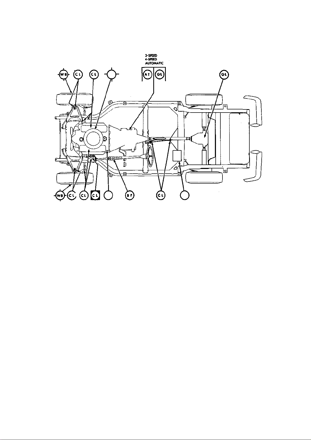
GENERAL INFORMATION AND MAINTENANCE 35
LUBRICATE EVERY 6,000 MILES
REPLACE EVERY 24,000 MILES
LUBRICATE EVERY 34,000 MILES
* REFILL POSITRACTION REAR AXLE
WITH SPECIAL LUBRICANT ONLY
GL-MULTI-PURPOSE OR
UNIVERSAL GEAR
LUBRICANT*
WB-WHEEL BEARING LUBRICANT
Lubrication points—1963 -74
grease gun. Wipe the grease fittings clean
before greasing in order to prevent the possibility of forcing any dirt into the component.
Wheel Bearings
Once every 24,000 miles, clean and repack
wheel bearings with a wheel bearing grease.
Use only enough grease to completely coat
the rollers. Remove any excess grease from
the exposed surface of the hub and seal.
It is important that wheel bearings be
properly adjusted after installation. Improperly adjusted wheel bearings can cause steering instability, front-end shimmy and wander, and increased tire wear. For complete
adjustment procedures, see the "Wheel
Bearing" section in Chapter 8.
CL-CHASSIS LUBRICANT
TRANSMISSION FLUID
BF-BRAKE FLUID
S AT-DEXRON AUTOMATIC
PUSHING AND TOWING
Corvettes equipped with either the Powerglide or Turbo Hydra-Matic automatic transmissions cannot be push-started. To pushstart a Corvette that has either a three-speed
or four-speed manual transmission, switch on
the ignition, select the highest forward gear
and keep the clutch pedal depressed until
suitable speed has been provided by the
pushing vehicle. When this speed, approximately 15 mph, is reached, slowly release the
clutch to start the engine.
Corvettes may be towed at speeds up to 35
mph and distances not over 50 miles with the
driveshaft in place, if no engine/drive-line
damage is present. If engine/drive-line damage is known or suspected, the driveshaft
should be disconnected before towing. Towing connections should not be made on
Page 41
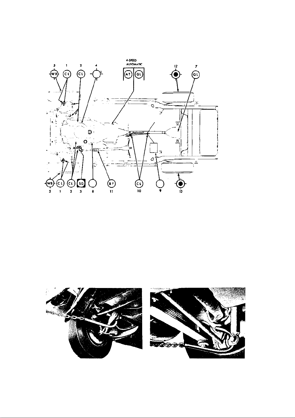
36 GENERAL INFORMATION AND MAINTENANCE
O
a
LUBRICATE EVERY7.500MILES
LUBSICATE FIRST 12,000 MILES
REPLACE EVERY 30,000«ILtS
CHECK FOR GREASE LEAKAGE
EVERY 30,000 MILES
REFILL POSITRACTION REAR AXLE
WITH SPECIAL LUBRICANT ONLY
1. Front suspension
2. Steering linkage
3. Steering gear
4. Air cleaner
5. Front wheel bearings
6. Transmission
GL-MULTI-PURPOSE OR
UNIVERSAL GEAR
LUBRICANT'
WB-WHEEL BEARING LUBRICANT
7. Rear axle
8. Oil filter
9. Battery
10. Parking brake
11. Brake master cylinder
12. Rear wheel inner bearing
CL-CHASSIS LUBRICANT
AT-DEXRON-H® AUTOMATIC TRANSMISSION FLUID
BF-BRAKE FLUID SG-STEERING
GEAR LUBRICANT
Lubrication points—1975-82 typical
Front towing point Rear towing point
Page 42
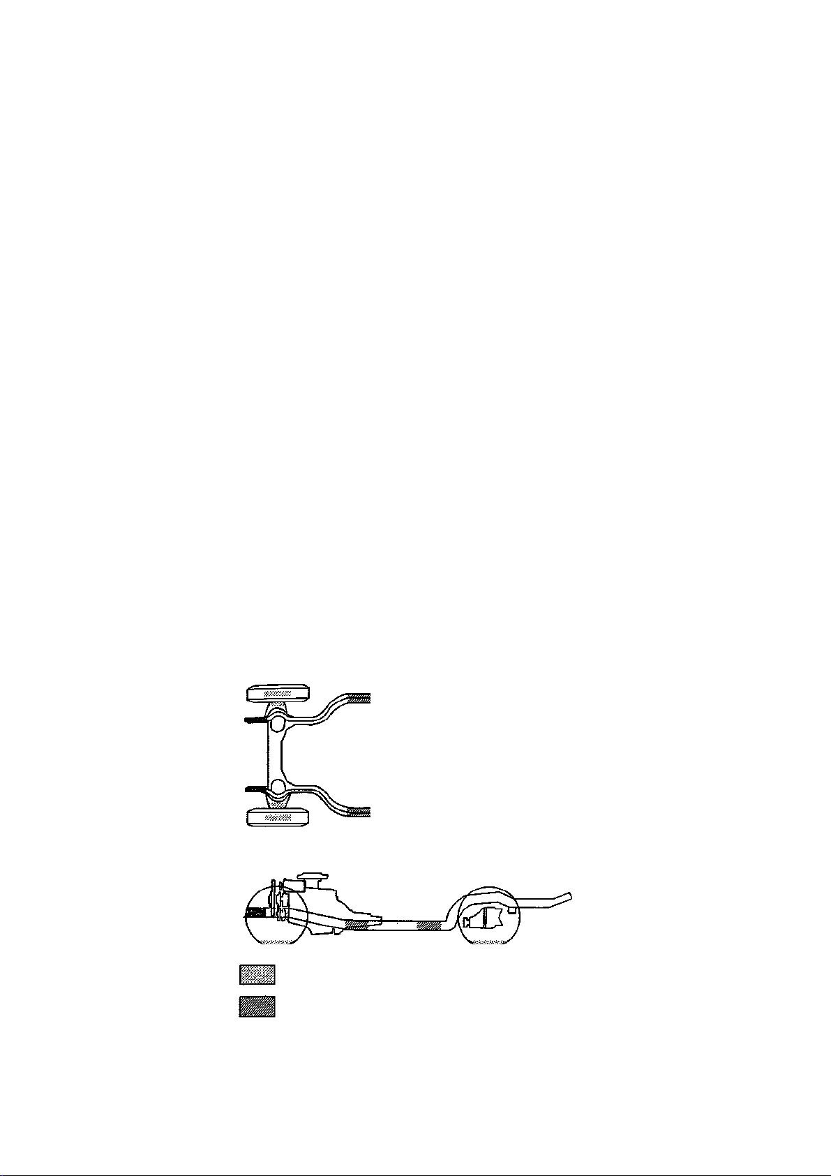
GENERAL INFORMATION AND MAINTENANCE 37
bumpers, only on the spindle struts at the rear
and the frame crossmember or lower control
arm at the front.
JUMP STARTING
The following procedure is recommended by
the manufacturer. Be sure that die booster
battery is 12 volt with negative ground.
CAUTION: Do not attempt this procedure
on a frozen battery; it will probably explode.
Do not attempt it on a sealed Delco Freedom
battery showing a light color in the charge
indicator. Be certain to observe correct
polarity connections. Failure to do so will
result in almost immediate alternator and
regulator destruction. Never allow the
jumper cable ends to touch each other.
1. Position the 2 vehicles so that they are
not touching. Set the parking brake and place
automatic transmissions in Park and manual
transmissions in Neutral. Turn of the lights,
heater and other electrical loads.
2. Remove the vent caps from both the
booster and discharged battery. Lay a cloth
over the open vent cells of each battery. This
isn't necessary on batteries equipped with
sponge type flame arrestor caps, and it isn't
possible on sealed Freedom batteries.
3. Attach one cable to the positive (+) ter
minal of the booster battery and the other end
to the positive terminal of the discharged bat
tery.
4. Attach one end of the remaining cable
to the negative (—) terminal of the booster
battery and the other end to the alternator
bracket. Do not attach to the negative ter
minal of discharged batteries.
5. Start the engine of the vehicle with the
booster battery. Start the engine of the vehi
cle with the discharged battery. If the engine
will not start, disconnect the batteries as soon
as possible. If this is not done, the two bat
teries will soon reach a state of equilibrium,
with both too weak to start an engine. This
will not be a problem if the engine of the
booster vehicle is kept running fast enough.
Lengthy cranking can also overheat and dam
age the starter.
6. Reverse the above steps to disconnect
the booster and discharged batteries. Be cer
tain to remove negative connections first.
7. Reinstall the vent caps. Dispose of the
cloths; they may have battery acid on them.
CAUTION: The use of any "hot shot" type
of jumper system in excess of 12 volts can
damage the electronic control units on late
model engines with computer controls.
JACKING AND HOISTING
The jack supplied with the Corvette was
meant for changing tires. It was not meant to
support a vehicle while you crawl under it
and work. Whenever it is necessary to get
under a vehicle to perform service opera-
DRIVE-ON HOIST, TWO-POST HOIST
WITH DRIVE-ON ADAPTORS
FLOOR JACK, JACKSTANDS,
CENTER POST HOIST
Jacking and hoisting points
JACK STANDS
Page 43

38 GENERAL INFORMATION AND MAINTENANCE
tions, always be sure that it is adequately
supported, preferably by jackstands at the
proper points. Always block the wheels when
changing tires.
Since the Corvette is equipped with a Positraction rear axle, do not run the engine for
any reason with one rear wheel off the ground.
Power will be transmitted through the rear
wheel remaining on the ground, possibly
causing the vehicle to drive itself off the jack.
Some of the service operations in this book
require that one or both ends of the vehicle
be raised and supported safely. The best arrangement for this, of course, is a grease pit
or a vehicle lift, but these items are seldom
found in the home garage. However, small
hydraulic, screw, or scissors jacks are satisfactory for raising the vehicle.
Heavy wooden blocks or adjustable jackstands should be used to support the vehicle
while it is being worked on. Drive-on trestles, or ramps, are also a handy and a safe way
to raise the vehicle, assuming their capacity
is adequate. These can be bought or constructed from suitable heavy timbers or
steel.
In any case, it is always best to spend a
little extra time to make sure that your Corvette is lifted and supported safely.
CAUTION: Concrete blocks are not rec-
ommended. They may crumble if the load
is not evenly distributed. Boxes and milk
crates of any description must not be used.
Shake the vehicle a few times to make sure
the jack stands are securely supporting the
weight before crawling under.
Page 44
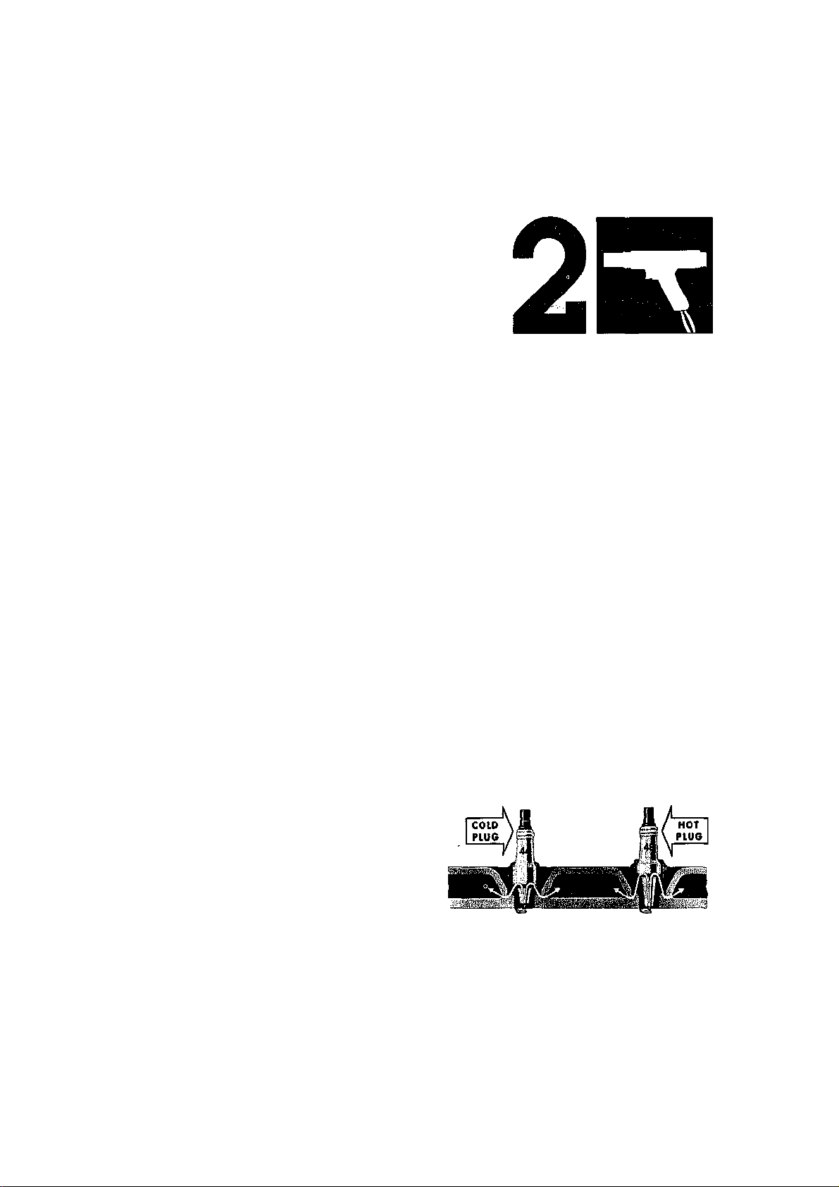
Tune-Up and
COLDER
HOTTER
Spark plug heat range, the higher the number the
hotter the plug
Performance Maintenance
TUNE-UP PROCEDURES
This section gives specific procedures on how
to tune-up your Corvette. It is intended to be
as complete and as basic as possible. Those
who are familiar widi die steps involved in a
tune-up may wish to slap die following procedures and use die generalized section in
chapter 10. However, it is felt that nothing
would be lost by first reading over tins section. Perhaps the best procedure to follow
would be to read botii sections before starting your tune-up.
Spark Plugs
A typical spark plug consists of a metal shell
surrounding a ceramic insulator. A metal
electrode extends downward through the
center of die insulator and protrudes a small
distance. Located at the end of the plug and
attached to die side of die outer metal shell
is the side electrode. The side electrode bends
in at a 90° angle so diat its tip is even witii,
and parallel to, the tip of the center electrode. The distance between diese two electrodes (measured in tiiousandths of an inch)
is called the spark plug gap. The spark plug
in no way produces a spark but merely provides a gap across which the current can arc.
The coil produces anywhere from 20,000 to
40,000 volts which travels to die distributor
where it is distributed through die spark plug
wires to die spark plugs. The current passes
along die center electrode and jumps die gap
to die side electrode, and, in so doing, ignites die air/fuel mixture in die combustion
chamber.
die fartiier it extends into die engine), die
hotter the plug will operate; the shorter the
insulator die cooler it will operate. A plug tiiat
absorbs littie heat and remains too cool will
quickly accumulate deposits of oil and carbon
since it is not hot enough to burn diem off.
This leads to plug fouling and consequendy
to misfiring. A plug diat absorbs too much
heat will have no deposits, but, due to die
excessive heat, die electrodes will burn away
quickly and in some instances, preignition
may result. Preignition takes place when plug
tips get so hot diat diey glow sufficiendy to
ignite die fuel/air mixture before die actual
spark occurs. This early ignition will usually
cause a pinging during low speeds and heavy
loads.
The general rule of tiiumb for choosing die
correct heat range when picking a spark plug
is: if most of your driving is long distance,
high speed travel, use a colder plug; if most
of your driving is stop and go, use a hotter
plug. Original equipment plugs are compromise plugs, but most people never have oc-
SPARK PLUG HEAT RANGE
Spark plug heat range is the ability of die plug
to dissipate heat. The longer die insulator (or
Page 45

40 TUNE-UP AND PERFORMANCE MAINTENANCE
s
•I
CO
o
1
(0
a
I
tO CD B
= ll
Mil
0 ©
0 ©
'SP
ZJ4
ill
©
© 0 ©
©
©
s
CO CO
©
© ©
q d
s
0
CD
q d
CM CO
3
q d
©
©
©
1
sd
5
5
3-
1
in ?s!
8
g
Page 46

-
?
^
-
-----
-
---
-
-
-
-
•^
CO
J,
7
in
7
7
in
in
in
7
in
m
S
r
S
e
§
I
i
8
8
© © © g | ©
g
©
g
©
g
1
8
*
8 8
3
.
5
•
.
<
*
o
o
0 0 © ©
1
©
©
§
©
0
d
© § ©
©
1 i © © © © o § © ©
© § § © ©
§
o
® o
©
©
^
n
en
O
O
0
0
0
0
O
0
0
O r
-
1
7
7
1 7
7
7
7 7
7
7 7 1
7
8
8
8 in
8
m
8
8
8
8
8
1 in 8 in
8
m
8
8 in
8
in
8
8
8.
o o o o o o o o o o O o o o d o
'
'
*
'
'
1
©
i
I
©
.
XI
f
JZ
JC-C
JZ
JZ
JZ
o
s
o
§
8 8
8 8
1
1
1
I
1
e
?
e
CO
c
c
o
o
8
CO
TUNE-UP AND PERFORMANCE MAINTENANCE 41
•4
-v
CO
in
o
in
i
i
n
n
J,
i
n
©
7
in
7
|
8
f
.
J,
7
J
,
CO
*?
J,
7
§
%
g
2
S
©
8
s
CO
c
o
-v
7
in
©
8
e
n
I
CD
d d
d d
e
n
in
CO
o
e
e
l
CM
e
n
.
©
O
Q
CD
e
n
CM
CO
CM
CM
CM
in
co
o
5
*
©
e
o
o o
Tl
-
Cn
co
CM
CM
©
d
d
c
o
CO
CD
e
e
n
n
CO
CM
CM
in
CO
o
© ©
e
e
n
n
CM
CO
CM
A
in
CO
o
.
d d
d d
i
ffl
n
CM
e
e
n
n
CM
in
in
.
•
e
e
e
n
n
n
CM
CO
CO
A
in
in
CO
8
o
CO
in
T
i
r
o
0
.
c
TJ-
d
d d
CM
O)
e
n
in
0
o
CO
*
(O
CO
CM
©
d
1 ©
d
O
K
e
e
n
n
to O
CM
2 O)
CO
1-
in
in
CO
o
0
o
o
..
c
d
d
CO
e
n
•
7
^
in
8
0
o
1
a
.
CO
1 1
©
1
O.
§
r
-
I
a
.
8
CO
Q.
?
2
a
a
.
.
a
.
1
™
Q.
8
CO
1
a
.
§
a
.
S
©
1
a
a
a
.
.
.
*
1
Q. Q.
1
s
r
n
.
©
CM
5
R43N©
a
.
Q-
8 8
I
a
a
.
.
§
o
i
Q. Q.
1
t
r
1
tr
a
Page 47

Year
1971
1972
1973
1974
1975-76
1977
1978
1979
fO
Tune-Up Specifications (cont.)
H
Spark Plugs
Model
270 hp
330 hp
365 hp
425 hp
R44®
200 hp
R44T
255 hp
R44T
270 hp
R44T
190hp
R44T
250 HP
R44T
270 hp
R44T
195hp
R44T
250 hp
R44T
270 hp
R44T
165 hp
R44TX
205 hp
R44TX
180 hp
R45TS
210hp
R45TS
185 hp
R45TS
220 hp
R45TS
195 hp
R45TS
225 hp
R45TS
Type
R44TS
R43TS
R43TS
Gap
(In.)
0.035
0.035
0.035
0.035
0.035 29-31 0.019
0.035
0.035 28-30 0.019
0.035
0.035
0.035
0.035
0.035
0.035
0.060
0.060
0.045
0.045
0.045
0.045
0.045
0.045
Distributor
Point Point
Dwell Gap
(deg) (In.)
28-32 0.019
Transistor
Ignition
28-32 0.019
Transistor
Ignition
29-31 0.019
29-31 0.019
29-31 0.019
29-31 0.019
29-31 0.019
29-31 0.019
29-31 0.019
Electronic
Electronic
Electronic
Electronic
Electronic
Electronic
Electronic
Electronic
Valves
Basic Ignition
Timing (deg
BTDC)
Clearance (In.)
Intake Exhaust (deg BTDC)
llrtake
Idle
Speed
(rpm)
4® ® ® 26 600®
8© 0.024 0.030 36 700
8 ® ® 56 600
8 0.024 0.028 44 700
8 © © 26 800®
4 0.024 0.030 36 900
8 ® © 56 750®
12 ® ® 26© 900®®
8 ® ® 40 900®®
10 ® ® 56 900®®
8® ® ® 26© 900®
8 © © 40 900®
10 © © 56 800®
6 © © 26 800®
12 © © 40 900®
8 ® ® 26 800®
12 ® © 40 900®
6© © ® 26
12 ® ® 40
6© © ® 26 ®
12 ® © 40 ®
(®
fiS
Normal
Fuel
Pressure
(psl)
7V2-9
7'/2-9
7Va-9
7Va-9
7V2-9
7V2-9
7Vz-9
71/2-9
7V2-9
7V2-9
71/2-9
71/z-9
7Va-9
71/a-9
7Va-9
7V2-9
71/2-9
71/a-9
7'/2-9
71/2-9
71/2-9
Z
m c
o
•o m
30
3
39
O m
m
o m
Page 48

1980
6 ® a
® ® a
1981 190 hp® R45TS 0.045 Electronic
1982 200 hp R45TS 0.045 Electronic
1984 205 hp R45TS 0.045 Electronic
If the specifications listed on the tune-up sticker under the hood differ from those listed here, the sticker specifications take precedence.
ATDC — After top dead center
BTDC — Before top dead center
TDC — Top dead center
® Hydraulic lifters — one turn down from zero lash
® W/automatic transmission — 450
© W/automatic transmission — 2°ATDC
® W/automatic transmission and A.I.R. — 4°ATDC
©W/automatic transmission and A.I.R. — 700
© W/automatic transmission and A.I.R. — 750
© W/automatic transmission — 600
® W/automatic transmission — 4°BTDC
® W/automatic transmission — 8°BTDC
® W/automatic transmission — 550
© W/automatic transmission — 12°BTDC
©California models— 44°BTDC
©California models— 4°BTDC
O450 rpm w/idle solenoid disconnected
® Models with aluminum cylinder heads use A.C. R43XL
®W/automatJc transmission — 750
©California with automatic transmission — 8°BTDC
® Use the specification listed on the tune-up sticker under the hood
©California only
©Estimated
©High altitude models with automatic transmission — 8°BTDC
@ High altitude models with automatic transmission — 650
©W/automatic transmission — 500 ram
Note: Idle speeds of automatic transmission vehicles are checked with the transmission in Drive.
Note: Spark plugs listed are original equipment A.C. Delco. These listings are not recommendations by Chilton for any product by name.
180hp®
(305 eng.)
190 hp (350
eng.)
230 hp (350
eng.)
R45TS 0.045 Electronic
R45TS 0.045 Electronic
R45TS 0.045 Electronic
4 ® a
6© ® a
12 ® a
® ® a
) 28 ® 71/a-9
) 26 600® 71/z-9
) 40 800 7Va-9
) 38 700® 71/2-9
) NA ® 9-13
) NA ® 9-13
HI
2
Page 49
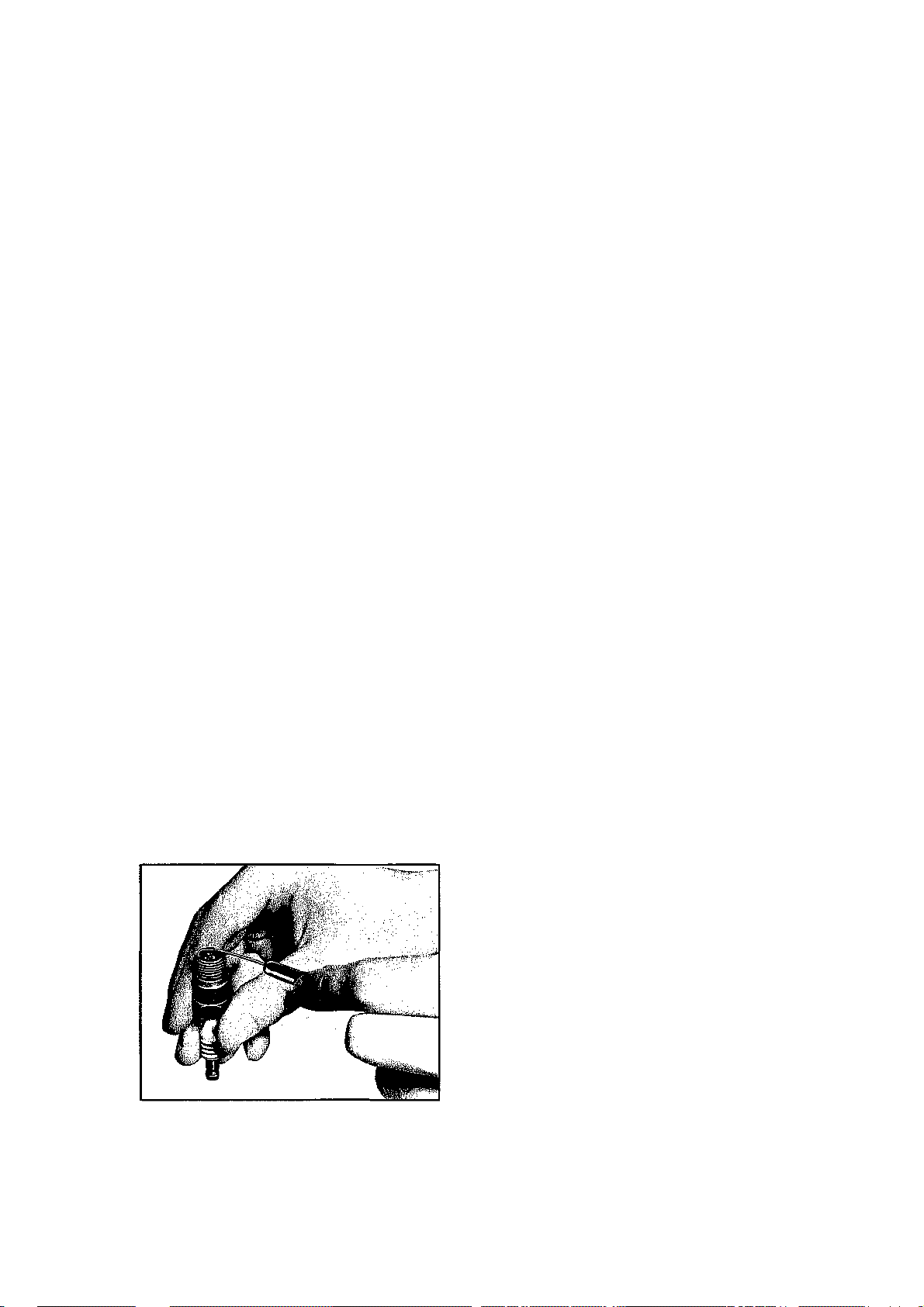
44 TUNE-UP AND PERFORMANCE MAINTENANCE
casion to change their plugs from the factoryrecommended heat range.
REPLACING SPARK PLUGS
Normally, a set of spark plugs requires replacement about every 10,000 miles on cars
with conventional ignition systems (incl.
Transistorized) and 20,000-30,000 miles on
cars equipped with an H.E.I. (High Energy
Ignition) system. Some earlier high performance engines may require more frequent
plug changes, especially if idled or operated
at low rpm's for extended periods. Any vehicle which is subjected to severe conditions
will need more frequent plug replacement.
In normal operation, plug gap increases
about 0.001 in. for every 1,000-2,500 miles.
As the gap increases, the plug's voltage requirement also increases. It requires a greater
voltage to jump the wider gap and about two
to three times as much voltage to fire a plug
at high speeds than at idle.
When you're removing spark plugs, you
should work on one at a time. Don't start by
removing the plug wires all at once, because
unless you number tiiem, they may become
mixed up. Take a minute before you begin
and number the wires with tape. The best
location for numbering is near where the
wires come out of the cap.
1. Remove the radio interference shields
which cover the spark plugs and wires (in
some models).
2. Twist the spark plug boot and remove
the boot and wire from the plug. Do not pull
on the wire itself as diis will ruin the wire.
3. If possible, use a brush or rag to clean
the area around the spark plug. Make sure
that all the dirt is removed so that none will
enter the cylinder after the plug is removed.
4. Remove the spark plug using the proper
Check the gap with a round wire gauge
size socket. (13/ie in. through 1971, % in. 1972
and later.) Turn the socket counterclockwise
to remove the plug. If the engine has aluminum cylinder heads, be extremely careful
when removing the plugs. If any plug turns
with difficulty, spray a penetrating lubricant
(Liquid Wrench, WD-40, etc.) around the
plug threads and turn the plug back in. Wait
a couple of minutes for the oil to work its way
through the threads and then "nurse" the plug
out about V-t turn at a time. Be sure to hold
the socket straight on the plug to avoid
breaking the plug, or rounding off the hex on
the plug.
5. Once the plug is out, check it against
die plugs shown in chapter 11 to determine
engine condition. This is crucial since plug
readings are vital signs of engine condition.
6. Use a round wire feeler gauge to check
die plug gap. The correct size gauge should
pass through the electrode gap with a slight
drag. If you're in doubt, try one size smaller,
and one larger. The smaller gauge should go
through easily while the larger one shouldn't
go through at all. If the gap is incorrect, use
the electrode bending tool on the end of the
gauge to adjust the gap. When adjusting the
gap, always bend the side electrode. The
center electrode is non-adjustable.
7. If die engine has cast-iron heads, squirt
a DROP of penetrating oil onto die plug
threads and install the plug. If the engine has
aluminum heads, apply a small amount of antisieze compound to die plug threads and care
fully install the plugs. Turn the plugs in by
hand until diey are snug.
8. When the plug is finger tight, tighten it
with a wrench.
9. Install die plug boot firmly over the
plug. Proceed to the next plug.
CHECKING AND REPLACING SPARK
PLUG CABLES
Visually inspect the spark plug cables for
burns, cuts, or breaks in die insulation. Check
die spark plug boots and die nipples on die
distributor cap and coil. Replace any damaged wiring. If no physical damage is obvious, the wires can be checked widi an
ohmmeter for excessive resistance. (See die
tune-up and troubleshooting section.)
When installing a new set of spark plug cables, replace the cables one at a time so there
will be no mixup. Start by replacing the longest cable first. Install die boot firmly over die
spark plug. Route die wire exacdy die same
as the original. Insert the distributor end of
Page 50
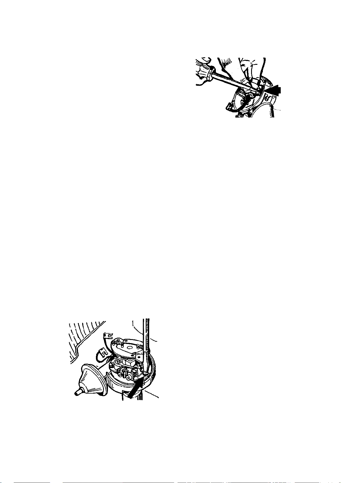
TUNE-UP AND PERFORMANCE MAINTENANCE 45
The points are retained by screws; use a mag
-
netic screwdriver to avoid losing them
the wire firmly into the tower on the distributor cap, then seat the boot over the tower.
Repeat the process for each cable.
NOTE: Always replace the points and con-
denser together. Uniset@ points are available which combine the point set and condenser, greatly simplifying installation.
Breaker Points and Condenser
REMOVAL AND REPLACEMENT
Point alignment is preset at the factory and
requires no adjustment. Point sets using the
push-in type wiring terminal should be used
on those distributors equipped with an R.F.I,
(radio frequency interference) shield (1970—
74). Points using a lockscrew type terminal
may short out due to the shield contacting
the screw.
NOTE: The optional magnetic pulse dis-
tributor and the HEI (High Energy Ignition) system used on some 1974 and all
1975—79 models requies no maintenance
other than checking the condition of the cap
and wires. There are no points to wear out
or adjust.
1. Remove the radio interference shield
from around the distributor. Unlatch and re
move the distributor cap.
2. Remove the rotor.
3. If so equipped, remove the two-piece
R.F.I. shield.
4. Loosen the two mounting screws and
slide the contact point set from the breaker
plate.
5. Remove the two wires which are con
nected to the point set.
6. Loosen the condenser bracket screw
and slide the condenser from the bracket.
7. Install the new point set and con
denser and then tighten the mounting screws.
The condenser is held In place by a screw and a
damp
8. Install the wires to the terminal so that
they will not interfere with the cap, weight
base, or breaker advance plate. Install the half
of the R.F.I. shield which covers the points
first.
9. Have an assistant "tap" the ignition key
to turn the engine until the rubbing block of
the point set is centered on one of the distrib
utor cam lobes. Turn the ignition key off.
10. Using a ¥s in. alien wrench, make an
initial point setting of 0.019 in.
11. The cam lubricator (if so equipped)
must be replaced after 12 months or 12,000
miles. The end of the lubricator should be
adjusted to just touch the cam lobes. Addi
tional grease should not be applied to the lu
bricator.
12. Install the rotor. The two lugs on the
bottom of the rotor are shaped differently, so
that it can only be installed one way. Tighten
the screws. Start the engine and check the
point dwell and the ignition timing.
Dwell Angle
Dwell angle is the amount of time (measured
in degrees of distributor cam rotation) that the
contact points remain closed. Initial point gap
(0.019 in.) determines dwell angle. If the
points are too wide they open gradually and
dwell angle (the time they remain closed) is
small. This wide gap causes excessive arcing
at the points and, because of this, point burning. This small dwell doesn't give the coil sufficient time to build up maximu m energy and
so coil output decreases. If the points are set
too close, the dwell is increased but the points
may bounce at higher speeds and the idle becomes rough and starting is made harder. The
wider the point opening, the smaller the dwell
and the smaller the gap, the larger the dwell.
Adjusting the dwell by making the initial point
gap setting with a feeler gauge is sufficient to
Page 51
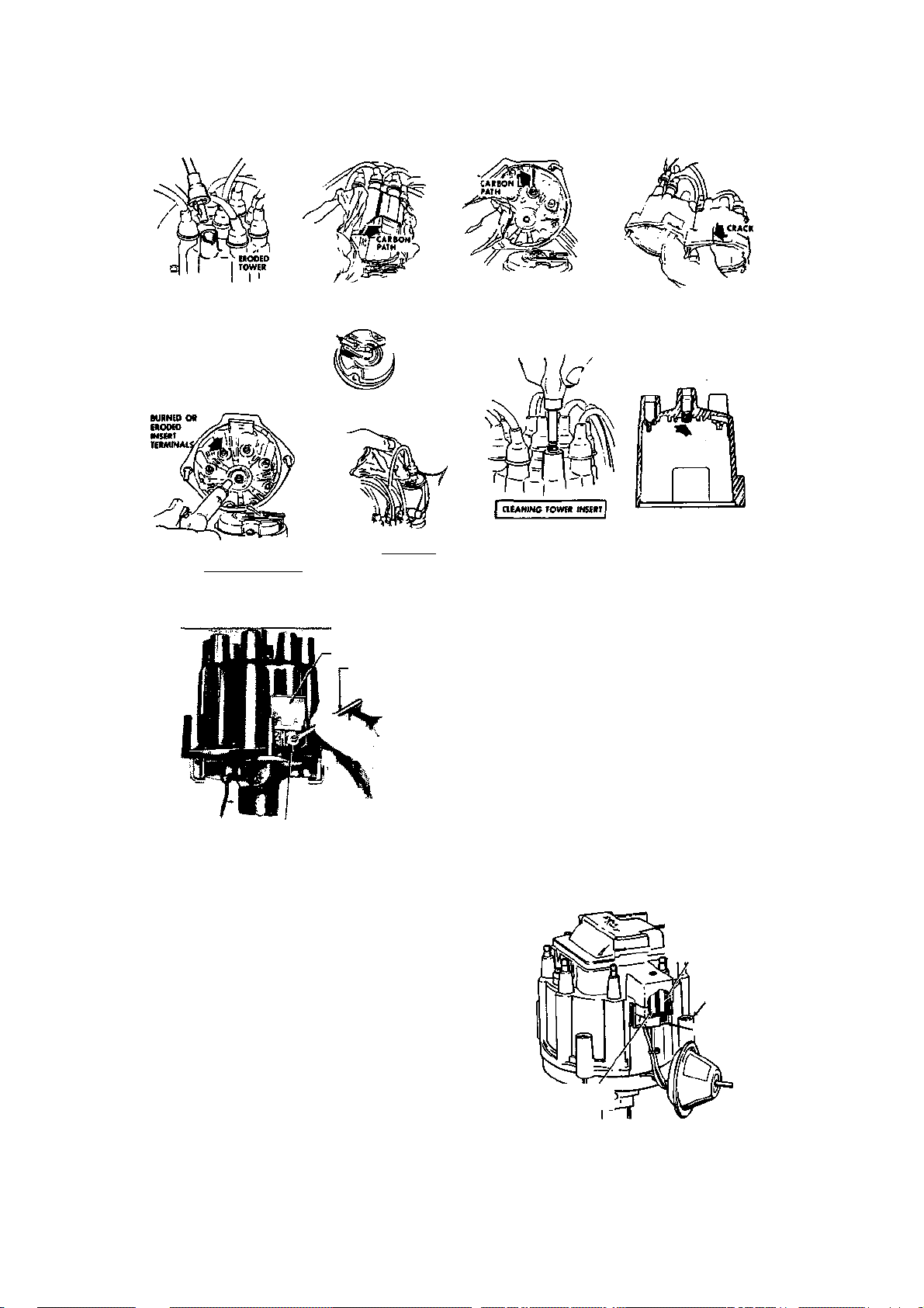
46 TUNE-UP AND PERFORMANCE MAINTENANCE
OUTSIDE OF DISTRIBUTOR CAP
INSUFFICIENT
ROTOR INSPECTION
CLEANING IGNITION
I
WINDOW
WRENCH
TERMINAL
LATCH
'CONNECTOR
THIS TERMINAL
INSPECTION OF DISTRIBUTOR CAP
TOWERS
CLEANING & INSPECTION OF I
RO
TOR TIP
CORROD
ED.
ROTOR CONTACT
SPRING TENSION
______
CPU
UOWING OUT INSIDE OF DISTRIBUTOR
CAP ft INSPECTION OF INSERT
________
TERMINALS
___________
Distributor cap and rotor checkpoints
ADJUSTING \ V
SCREW ^
Adjusting point gap (dwell angle) with 1/e in. alien
wrench
_______
"HEX" TYPE
get the car started but a finer adjustment
should be made. A dwell meter is needed to
check the adjustment.
NOTE: The ignition timing must be checked
and adjusted any time the point set is replaced or the dwell is changed. When the
dwell is increased, the ignition timing decreases, and vice-versa.
1. Run the engine to normal operating
temperatures and then let it idle.
2. Raise the adjusting window on the dis
tributor cap and insert a Vs in. alien wrench
into the adjusting screw.
3. Turn the adjusting screw until the spec-
CLEANING 1 INSPECTION OF
INSIDE OF DISTRIBUTOR CAP
REPLACING DISTRIBUTOR
CAP
_______
INSPECTION OF CAIBON I
aOTOa BUTTON I
ified dwell angle is obtained on the dwell meter.
HEI SYSTEM TACHOMETER HOOKUP
Connect one tach lead to the "TACH" terminal on the side of the distributor and the
other to ground. Some tachometers must be
connected to the "TACH" terminal and the
battery positive terminal. Not all tachometers will operate correctly with the HEI
system. Check with the manufacturer if there
is any doubt.
CAUTION: The "TACH" terminal should
never be connected to ground.
IGNITION WIRE
(BATTERY FEED)
(4)
CONNECT TACHOMETER Ti
Hook up one tach lead to the tachometer terminal on the HEI system
Page 52
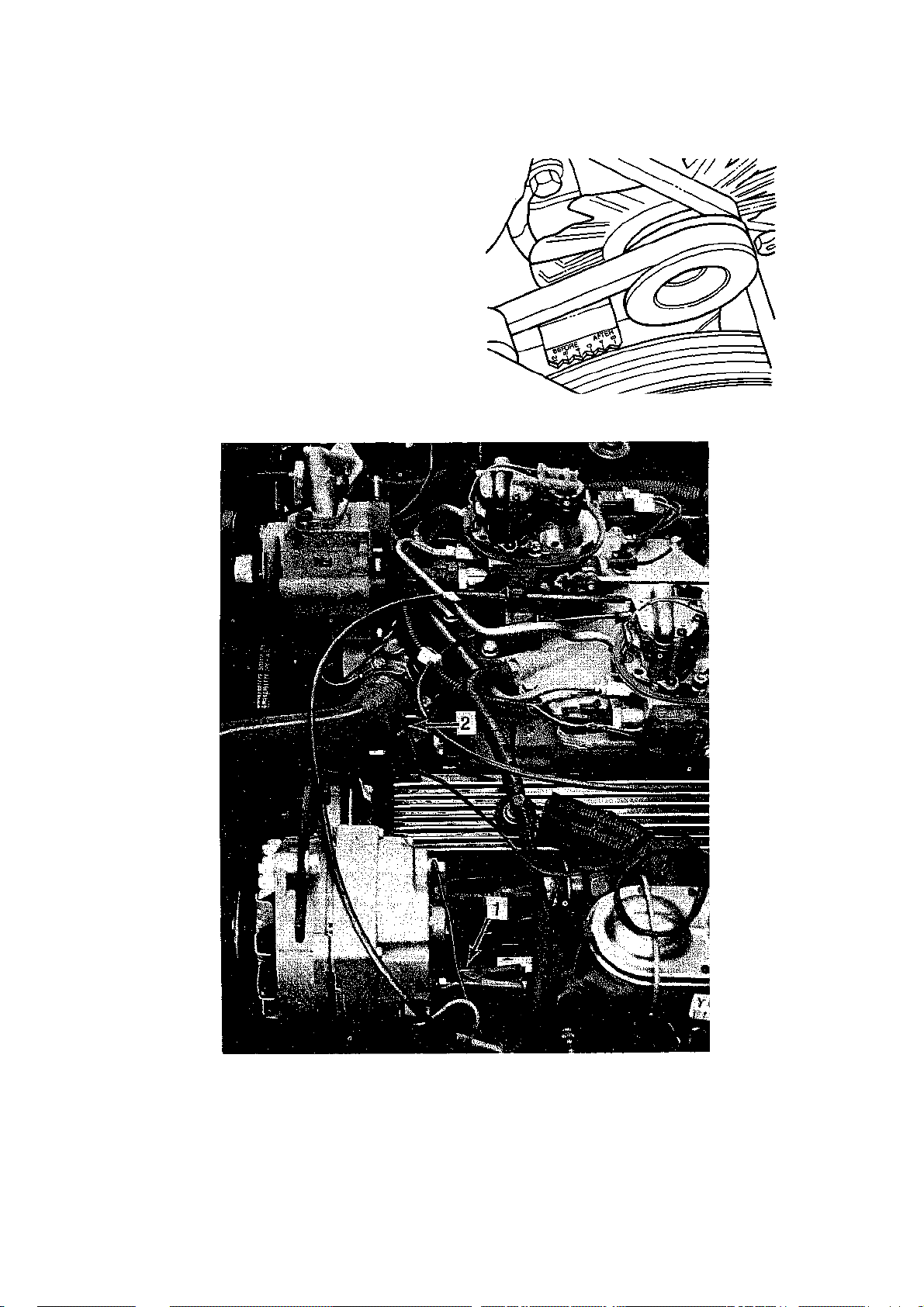
TUNE-UP AND PERFORMANCE MAINTENANCE 47
When hooking up a remote starter switch,
disconnect the "BAIT" terminal.
Ignition Timing Adjustment
1963-80
Except 1980 California
1. Warm the engine to normal operating
temperature and check the idle speed. Ad
just the idle speed to specifications, if neces
sary.
2. If so equipped, disconnect and plug the
vacuum advance hose from the distributor.
3. Connect a timing light according to the
timing light manufacturers instructions. DO
Timing mark location—typical
1. Positive (+) connection at the alternator BAT
terminal
2. Negative (-) connection at a good engine
ground
12VDC timing light power connections on a typical, externally regulated Delcotron
Page 53
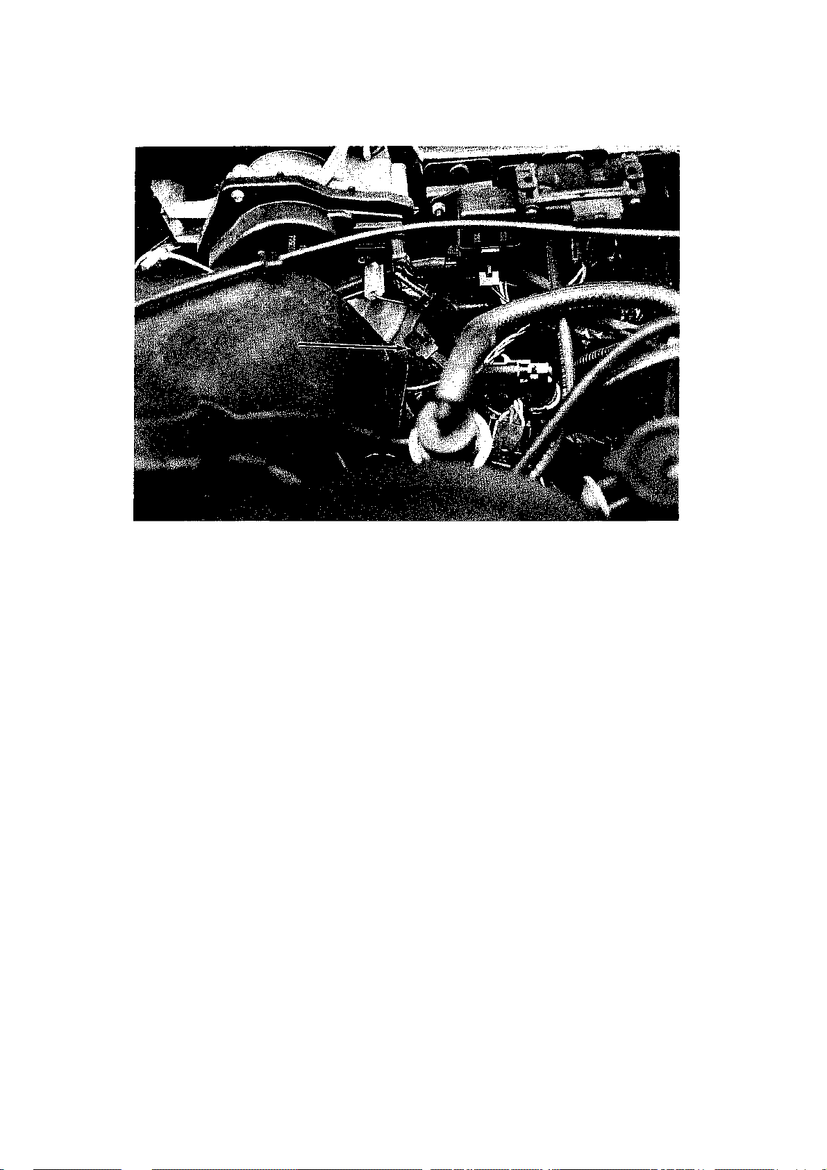
48 TUNE-UP AND PERFORMANCE MAINTENANCE
1982 EST BYPASS wire connector location. On these models, this connector must be separated prior to
setting the ignition timing—see text
NOT use a timing light which requires piercing of the spark plug lead. Timing lights which
have a lead that must be installed between
the plug and the plug wire may be used with
conventional ignition systems. On HEI ignition systems, use ONLY an inductive pickuptype timing light.
NOTE: Timing lights requiring a 12 volt
DC power source (battery) may be connected as follows: Connect the positive timing light lead to the BAT terminal of the
alternator; the negative timing light lead to
a good engine ground. CAUTION: Be
careful not to ground the positive lead to
the alternator case.
4. Locate the timing tab (metal tab marked
in graduations) which is attached to the tim
ing cover. Locate the single mark on the vi
bration damper (one groove). Clean both the
timing tab and the damper marking. Use chalk
to accentuate the marks if necessary.
5. Be sure that all wiring and tools are clear
of the fan and belts. Start the engine and al
low it to idle. Aim die timing light at the
marks and note where the vibration damper
mark aligns with die timing tab.
NOTE: The "O" marking on the tab is the
top dead center (TDC) mark and all the before top dead center (BTDC) marks are on
the "before" (advance] sice of the zero, or
the "A" (advance] side of zero. Later models
are marked to indicate Before and After.
6. Loosen the distributor clamp (holddown) bolt and slowly rotate the distributor
as necessary until the damper mark is aligned
with the specified mark of the timing tab.
Tighten the hold-down bolt and recheck the
timing.
7. Turn the engine off and remove the
timing light.
8. If so equipped, unplug and reconnect
the vacuum advance hose to the distributor.
7980 CALIFORNIA
Refer to the underhood emissions label for
the proper timing adjustment procedure.
1981
Refer to the underhood emissions label for
the proper timing adjustment procedure.
7982-84
The ignition timing of 1982-84 models is adjusted in basically the same manner as previously described (1963-80). The exception
to this is that the EST BYPASS wire from the
distributor must be disconnected prior to the
timing adjustment. Trace the four wires from
Page 54
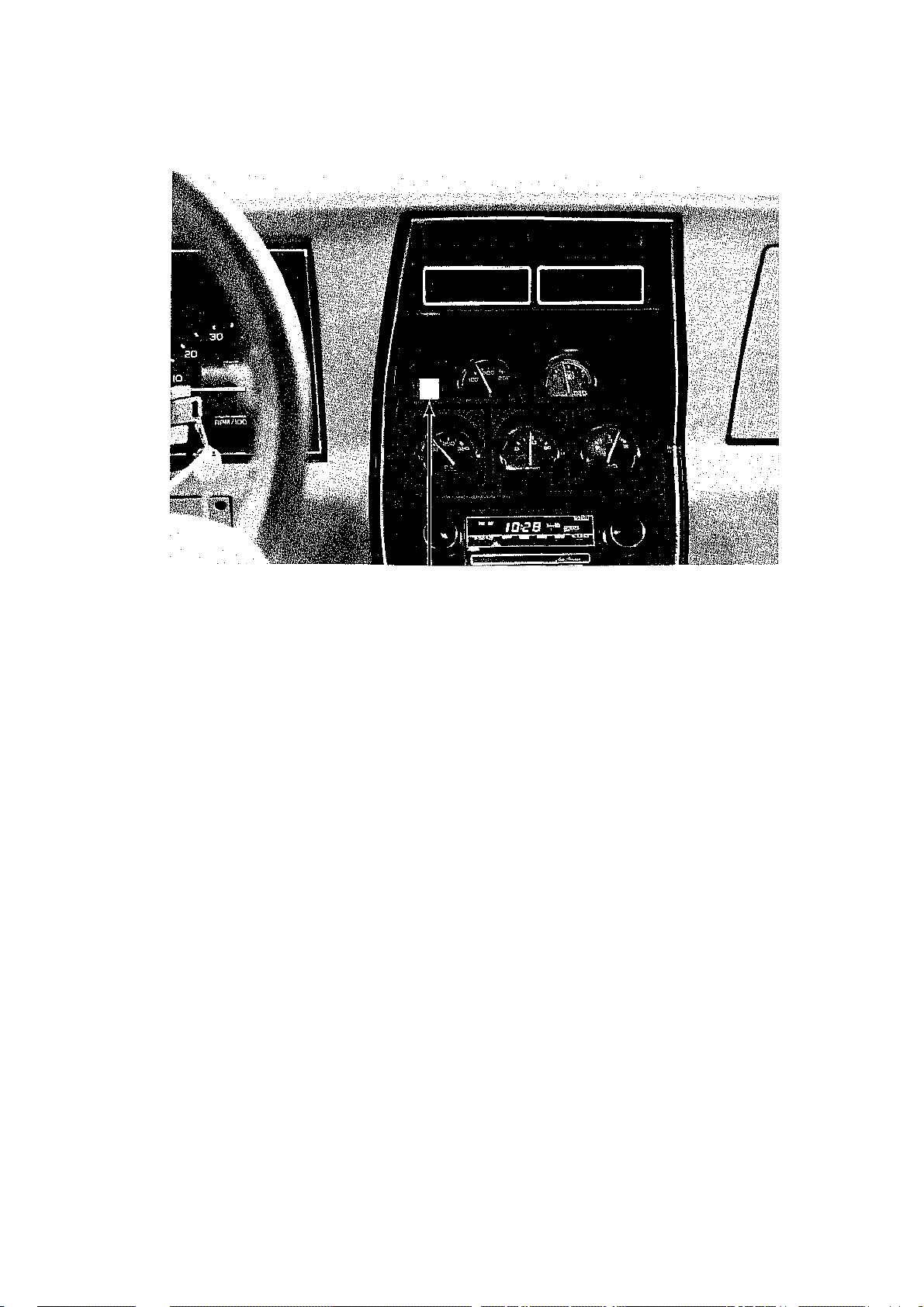
TUNE-UP AND PERFORMANCE MAINTENANCE 49
CHECK ENGINE lamp location. This lamp will be illuminated while the EST BYPASS wire is disconnected
the distributor housing which join at a common multi-connector, close to the distributor. Follow the tan wire with a black stripe
(EST BYPASS wire) from the multi-connector. Past the multiconnector, the EST BYPASS wire has its own, single connector.
NOTE: On 1984 models, disconnect the 4
terminal EST connector to operate in the
bypass timing mode.
Separate this connector before adjusting the
timing. While the EST BYPASS wire is disconnected, the CHECK ENGINE light on
the instrument panel will illuminate. After
adjusting the timing, reconnect the EST BYPASS connector; the CHECK ENGINE light
will go out.
NOTE: It is not necessary to adjust the idle
speed on 1982—84 models prior to the timing
adjustment, though the engine must be at
normal operating temperature. 1984
models incorporate an Electronic Spark
Control (ESC) into the distributor which
retards the spark advance when engine detonation occurs. If the controller fails, the result could be no ignition, no retard or full re-
tard. Some engines will also have a magnetic
timing probe hole for use with electronic timing equipment. Consult the manufacturer's
instructions for the use of this equipment.
Valve Lash
ADJUSTMENT
Engines equipped with hydraulic lifters
VERY rarely need adjustment of the valve
lash. If the vehicle runs well and there is no
audible "clicking" in the valvetrain, leave it
alone. This is because removal of the valve
covers on vehicles equipped with air conditioning, various emission controls, cruise
control, etc., can be a major project in itself.
On air conditioned models, the A/C compressor must be moved out of the way to gain
access to one of the valve covers. Do not disconnect the refrigerant lines to move the
compressor. After the cover is removed,
either move the compressor to retighten the
belt or remove the belt completely so that it
will not tangle while the engine is running.
On early models equipped with fuel injection, removal of the left valve cover requires
removal of the air cleaner hose, air meter
adaptor, and pyrometer housing.
If wiring is attached to metal clips on the
valve cover, carefully bend each clip to free
the wire from the valve cover. If corrugated
plastic tubing containing wiring is attached to
the valve cover with plastic clips, the clips
can be undone by gently twisting the upper
Page 55
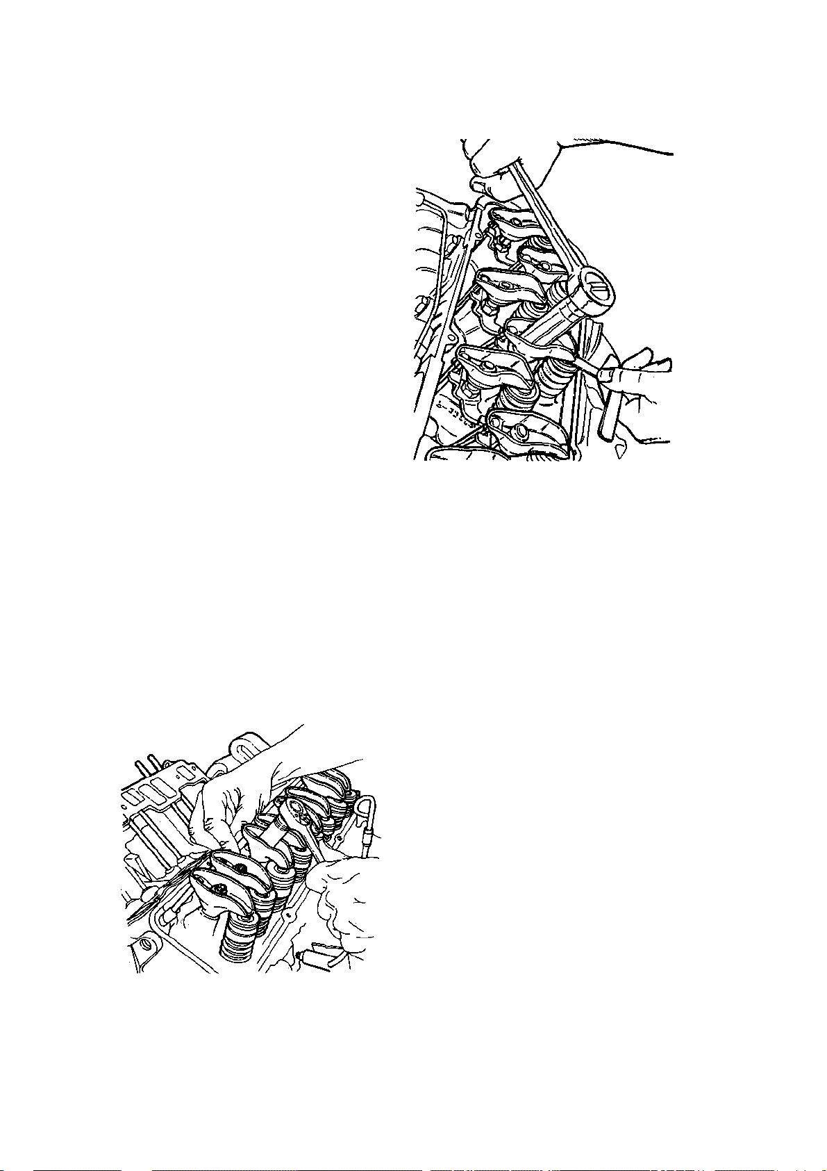
50 TUNE-UP AND PERFORMANCE MAINTENANCE
Adjusting the valve lash on a hydraulic lifter en
-
part of the clip while holding the lower section. If the clip must be removed, press the
lowermost arms of the clips together with
needle nose pliers and push upward.
If the vehicle uses a PCV valve pressed into
the valve cover grommet, pull the valve from
the grommet and remove the valve from the
hose. Plug the hose with an old bolt to prevent a vacuum leak. Models having a hose
running from the air cleaner to the exhaust
manifold require removal of the air cleaner
assembly and the hose. Plug any vacuum lines
which must be disconnected.
Should it be necessary to remove additional components to gain access to the valve
covers, note the wire and/or vacuum hose
connection locations and sizes of the bolts
which retain the components).
1. Purchase oil stopper clips for the rocker
arms. These are available at most auto parts
stores. These clips are installed either over
(metal style) or in (plastic style) the rocker arm
oiling hole located at the pushrod end of the
rocker arm. If these clips are not installed,
both you and your Corvette will become oil
soaked when the engine is started.
2. Start the engine and allow it to reach
normal operating temperature.
3. Remove the valve covers. If you have
only 8 oil stopper clips, remove only one valve
cover and adjust the valves. Then adjust the
valves on the other side after the first cover
has been reinstalled.
4. Start the engine and allow it to idle.
5. HYDRAULIC LIFTER ENGINES:
Slowly loosen the rocker arm nut until the
rocker arm starts to clatter. Tighten the nut
Adjusting the solid valve lifters
(clockwise) just until the clatter stops. This
position is what is termed "zero lash". Slowly
tighten the nut VA turn then wait about ten
seconds for the idle to smooth out. Repeat
this until the nut is tightened one full turn
past zero lash.
CAUTION: You must wait until the engine
smooths out after each V* turn past zero
lash. Impatience in this case can cause en-
gine damage due to valve interference.
Repeat step 5 for each remaining valve. 5A.
MECHANICAL (SOLID) LIFTER
ENGINES: Find your intake and exhaust
valve adjusting specs in the Tune-Up chart.
Use feeler gauges the same thickness as the
adjusting specs. Insert the appropriate feeler
gauge between the rocker arm and the valve.
The feeler gauge should fit with a slight drag.
If the gauge does not fit, loosen the rocker
adjusting nut until it does. Tighten the adjusting nut until the gauge can be moved with
a slight pull. Repeat step 5A for each remain-
6. Remove the oil stopper clips and rein
stall the valve covers.
7. Reinstall and/or reconnect and related
items.
ing valve.
gine
idle Speed and Mixture
Adjustment
Idle mixture and speed adjustments are critical aspects of exhaust emission control. It is
Page 56
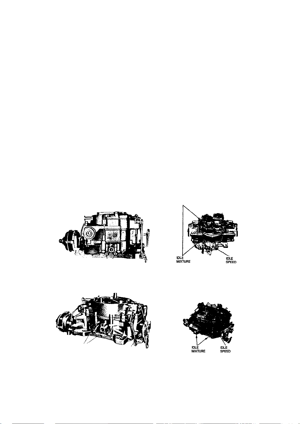
TUNE-UP AND PERFORMANCE MAINTENANCE 51
HOLLEY4150
important that all tune-up instructions be
carefully followed to ensure satisfactory engine performance and minimum exhaust pollution. The different combinations of emission systems application on the different
engine models have resulted in a great variety of tune-up specifications. See the "TuneUp Specifications" chart at the beginning of
this chapter. Beginning in 1968, all models
have a decal conspicuously placed in the engine compartment giving tune-up specifications.
When adjusting a carburetor with two idle
mixture screws, adjust them alternately and
evenly, unless otherwise stated.
In the following adjustment procedures the
term "lean roll" means turning the mixture
adjusting screws in (clockwise) from optimum
setting to obtain an obvious drop in engine
speed (usually 20 rpm).
NOTE: Due to the camshaft design of some
special high performance engines (350/LT.I,
427IL88,454/LS6, etc.) it is normal for these
engines to have a "lopey" idle.
1963-67 WITHOUT A.I.R.
NOTE: Adjust with air cleaner removed. 1.
Connect a tachometer and vacuum
gauge to the engine, then set the parking
brake and shift the manual transmission into
Neutral, automatic into Drive.
2. Turn the idle mixture screw(s) in until
lightly seated, then back out IVz turns.
3. With engine running, adjust the idle
speed screw to obtain the specified rpm.
4. Adjust the idle mixture screw(s) to ob
tain the highest steady manifold vacuum at
the specified speed. If necessary, reset the
idle speed screw while adjusting mixture.
NOTE: On air conditioned models, the air
conditioner is turned on and the hot idle
compensator valve is held closed while adjusting idle speed and mixture.
5. Final adjustment should be made with
the air cleaner installed.
6. Remove tachometer and vacuum gauge.
1966-67 WITH A.I.R.
Adjust with air cleaner removed.
1. Connect a tachometer to the engine,
place manual transmission in Neutral, auto
matic in Drive.
2. Turn idle mixture screw(s) in until
lightly seated, then back out 3 turns.
IDLE MfXTURE |
SCREWS SCREW
Carter WCFB idle mixture and speed adjustment screws
screws
IDLE MIXTURE /"
ADJUSTING SCREWS
Carter AFB idle mixture and speed adjustment
screws
IDLE
SPEED /
ADJUSTING SCREW
DLE
SPEED
Holley 4150 idle mixture and speed adjustment
Rochester Quadrajet idle mixture and speed adjustment screws
ROCHESTER 4MV
Page 57

52 TUNE-UP AND PERFORMANCE MAINTENANCE
Holley 2300 idle mixture and speed adjustment
screws
3. With engine running, adjust the idle
speed screw to obtain the specified idle speed.
4. Adjust the idle mixture screw(s) in to
"lean roll" position, then back them out (rich)
V* turn. Readjust the idle speed screw to keep
the engine at the specified idle speed while
adjusting the mixture.
NOTE: On air conditioned cars, turn the
air conditioner off with 327 cu in. engines.
Air conditioner must be on and hot idle
compensator held closed with 427 cu in.
engines.
5. Final adjustment should be made with
the air cleaner installed.
6. Remove the tachometer.
1968-69
Adjust with air cleaner installed.
1. Turn the idl e mixture screw(s) in until
lightly seated, then back out 3 turns.
2. With engine at operating temperature,
adjust idle speed screw to obtain specified
rpm, manual transmissiopn in Neutral and
automatic in Drive.
NOTE: On all 1968 models except 350 H.P.
327 cu. in. with manual transmission, the
air conditioner is turned off. On the abovementioned vehicles the air conditioner is left
on. On 1969 models, turn the air conditioner either on or off according to the instructions on the tune-up decal.
3. Adjust one idle mixture screw to obtain
the highest steady idle speed.
4. Adjust the idle speed screw to the speed
specified on the tune-up decal.
NOTE: On models equipped with an idle
solenoid, adjust the solenoid plunger hex to
obtain 600 rpm. Disconnect the wire at the
solenoid to deenergize it, allowing the
throttle lever to contact the carburetor idle
speed screw. Adjust the carburetor idle
HOLLEY 2300C (PRIMARY)
speed screw. Adjust the carburetor idle
screw to obtain 400 rpm.
5. Adjust the mixture screw in to "lean roll"
position, then back out (rich) % turn.
6. Repeat Steps 3, 4, and 5 for the other
idle mixture screw.
7. Readjust the idle speed screw to obtain
final specified rpm, if necessary.
1970
Adjust with air cleaner installed.
If the vehicle is equipped with Evaporative Emission, disconnect the fuel tank line
from the vapor canister while making the idle
speed and mixture adjustments. Warm up the
engine and leave it running while adjusting.
The choke valve and, if applicable, air cleaner
damper door should remain open. Leave the
air conditioning off.
350 (300, 350 and 370 hp) Engines
1. Adjust the idle mixture screws equally
to obtain maximum idle speed.
2. On the 300 H.P. engine width manual
transmission in Neutral adjust the idle speed
screw to obtain 700 rpm. On the 300 H.P.
engine with automatic transmission in Drive,
adjust the idle speed screw to obtain 600 rpm.
3. On the 350 and 370 H.P. engines, ad
just the idle speed screw to obtain 750 rpm
with the manual transmission in Neutral.
454 (450 hp) Engine
1. Remove the air cleaner.
2. Disconnect the distributor vacuum hose
at the distributor and plug the hose.
3. Adjust the mixture screws for maximum
idle speed.
4. With manual transmission in Neutral,
adjust the carburetor idle speed screw to ob
tain 750 rpm. With automatic transmission in
Drive, adjust the carburetor idle speed screw
to obtain 700 rpm.
5. Turn one idle mixture screw to obtain a
20 rpm drop in idle speed, then back the
screw out % turn. Repeat for the second idle
mixture screw.
6. Repeat Step 4 above.
7. Reconnect the distributor vacuum hose
and install the air cleaner.
454 (345 hp) and 454 (390 hp)
Engines
1. Disconnect the distributor vacuum hose
at the distributor and plug the hose.
2. Turn the idle mixture screws in until
Page 58
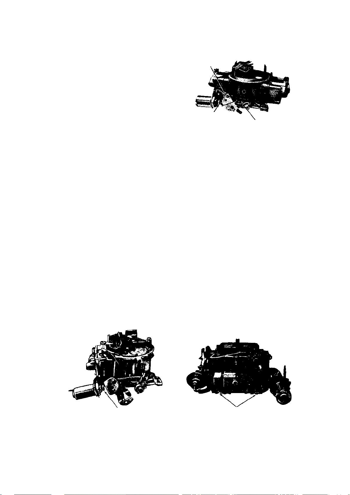
TUNE-UP AND PERFORMANCE MAINTENANCE 53
Rochester Quadrajet
speed screw
they are lightly seated, then back them out 4
turns.
3. With automatic transmission in Drive,
adjust the carburetor idle speed screw to ob
tain 630 rpm. Adjust the idle mixture screws
in equally to obtain 600 rpm.
4. With manual transmission in Neutral,
adjust the carburetor idle speed screw to ob
tain 700 rpm. Turn one of die mixture screws
in until the engine speed drops 40 rpm.
Readjust the idle speed screw to obtain 700
rpm. Turn in the other mixture screw until
die engine speed drops 40 rpm. Readjust the
idle speed screw to obtain 700 rpm.
5. Reconnect the distributor vacuum hose.
1971
Adjust with air cleaner installed.
The following initial idle adjustments are
part of the normal engine tune-up. There is a
tune-up decal placed conspicuously in the
engine compartment outlining the specific
procedure and settings for each engine application. Follow all of the instructions when
adjusting the idle. These tuning procedures
are necessary to obtain the delicate balance
of variables for the maintenance of both reliable engine performance and efficient exhaust emission control.
NOTE: All engines except the 350 (330
hp) and 454 (425 hp) have limiter caps
on the mixture-adjusting screws. The idle
mixture is preset and the limiter caps installed at the factory in order to meet emission control standards. Do not remove these
limiter caps unless all other possible causes
of poor idle condition have been thoroughly checked out.
The solenoid used on 1971 carburetors is
different from the one used on earlier models.
IDLE MIXTURE
SOLENOID SCREW
CARBURETOR (IDLE SPEED) SCREW
Holley 4150 (with idle solenoid) idle mixture and
speed adjustment locations
Combination Emission Control System
(C.E.C. solenoid) valve regulates distributor
vacuum as a function of transmission gear position.
CAUTION: The C.E.C. solenoid is ad-
justed only after: 1) replacement of the solenoid, 2) major carburetor overhaul, or 3)
after the throttle body is removed or replaced.
All initial adjustments described below are
made:
1. With the engine warmed up and run
ning.
2. With the choke fully open.
3. With die fuel tank gas cap removed.
4. With die vacuum hose disconnected at
the distributor and plugged.
Be sure to reconnect the distributor vacuum hose and to connect the fuel tank to
evaporative emission canister line or install
die gas cap when idle adjustments are complete.
350 (4-BBL Quadrajet) Engines
Adjust the carburetor idle speed screw (NOT
die solenoid plunger) to obtain 600 rpm
(manual transmission in Neutral widi the air
IDLE SPEED (SOLENOID) SCREW
(with idle solenoid) idle
IDLE MIXTURE SCREWS
Rochester Quadrajet (with idle solenoid) idle mixture screws
Page 59

54 TUNE-UP AND PERFORMANCE MAINTENANCE
conditioner off) or 550 rpm (automatic transmission in Drive with the air conditioner on).
350 and 454 (4-BBL Holley) Engines
1. Adjust the carburetor idle speed screw
(NOT the solenoid plunger) to obtain 700 rpm
(manual transmission in Neutral or automatic
transmission in Drive).
2. Adjust the idle mixture screws alter
nately to obtain the maximum smooth idle
speed.
3. Adjust one of the idle mixture screws to
obtain a 20 rpm drop ("lean roll"), then back
it out %, turn.
4. Repeat Step 4 above for the other idle
mixture screw.
5. Readjust the carburetor idle speed screw
to obtain 700 rpm if necessary.
454 (4-BBL Quadrajet) Engines
Turn the air conditioner off. Adjust the carburetor idle speed screw (NOT the solenoid
plunger) to obtain 600 rpm (manual transmission in Neutral or automatic transmission in
Drive).
1972
NOTE: All carburetors are equipped with
idle limiter caps and idle mixture is preset
at the factory and should not require adjustment.
1. Remove the fuel filler cap but do not
remove the vapor line.
2. Detach the distributor va cuum hose and
plug the hose.
3. Set the parking brake and turn the air
conditioner (if so equipped) off. On cars
equipped with an automatic transmission,
check the wheels.
4. Allow the engine to reach normal oper
ating temperature. Be sure that the choke is
open.
5. If the car has an automatic transmis
sion, set the selector in Drive. If the car has
a manual transmission keep die transmission
in Neutral.
6. Adjust the anti-dieseling solenoid to the
higher of the two rpm figures given in the
specifications.
CAUTION: Do not turn the solenoid more
than one complete turn unless the electrical
lead is disconnected (solenoid deenergized).
7. Disconnect the solenoid lead and set the
idle speed to the lower of the two figures given
in the specifications. Use the normal idle
speed adjusting screw.
NOTE: If no lower figure is given, adjust
the idle to 450 rpm.
8. Reconnect all of the wires and hoses
which were disconnected in order to perform
these adjustments.
1973
Ah1 models are equipped with idle limiter caps
and idle solenoids. Disconnect the fuel tank
line from die evaporative canister. The engine must be running at operating temperature, choke off, parking brake on, and rear
wheels blocked. Disconnect the distributor
vacuum hose and plug it. After adjustment,
reconnect the vacuum and evaporative hoses.
Four-barrel 350 and 454 cu in. V8s
1. Adjust the idle stop solenoid screw for
900 rpm on manual, 600 rpm on automatic.
2. Connect the distributor vacuum hose
and position the fast idle cam follower on the
top step of the fast idle cam (turn air condi
tioning off) and adjust die fast idle to 1300
rpm on manual transmission 350 engines;
1600 on manual 454 engines and all automat
ics (in Park).
Optional 350 cu in. (L82) V8
1. Adjust the idle stop solenoid screw (air
conditioning off) for a speed of 900 rpm on
manual transmission; 700 rpm on automatic
(in Drive).
2. Connect the distributor vacuum hose
and position the fast idle cam follower on the
top step of the cam (turn air conditioning off)
and adjust the fast idle to 1300 rpm on man
ual; 1600 rpm on automatic.
1974
The same preconditions as for 1973 apply.
Four-barrel 350 cu in. V8
1. Turn the air conditioning off. Adjust the
idle stop solenoid screw for 900 rpm on man
ual transmission models; 600 rpm on auto
matic (in Drive).
2. Connect the distributor vacuum hose.
Position the fast idle cam follower on the top
step of the fast idle cam and adjust the fast
idle speed to 1300 rpm on manual; 1600 on
automatic (in Park).
Optional 350 cu in. (L82) V8
1. Turn the air conditioning off. Adjust the
idle stop solenoid for 900 rpm on manual; 700
rpm on automatic (in Drive).
2. Connect the distributor vacuum hose.
Page 60
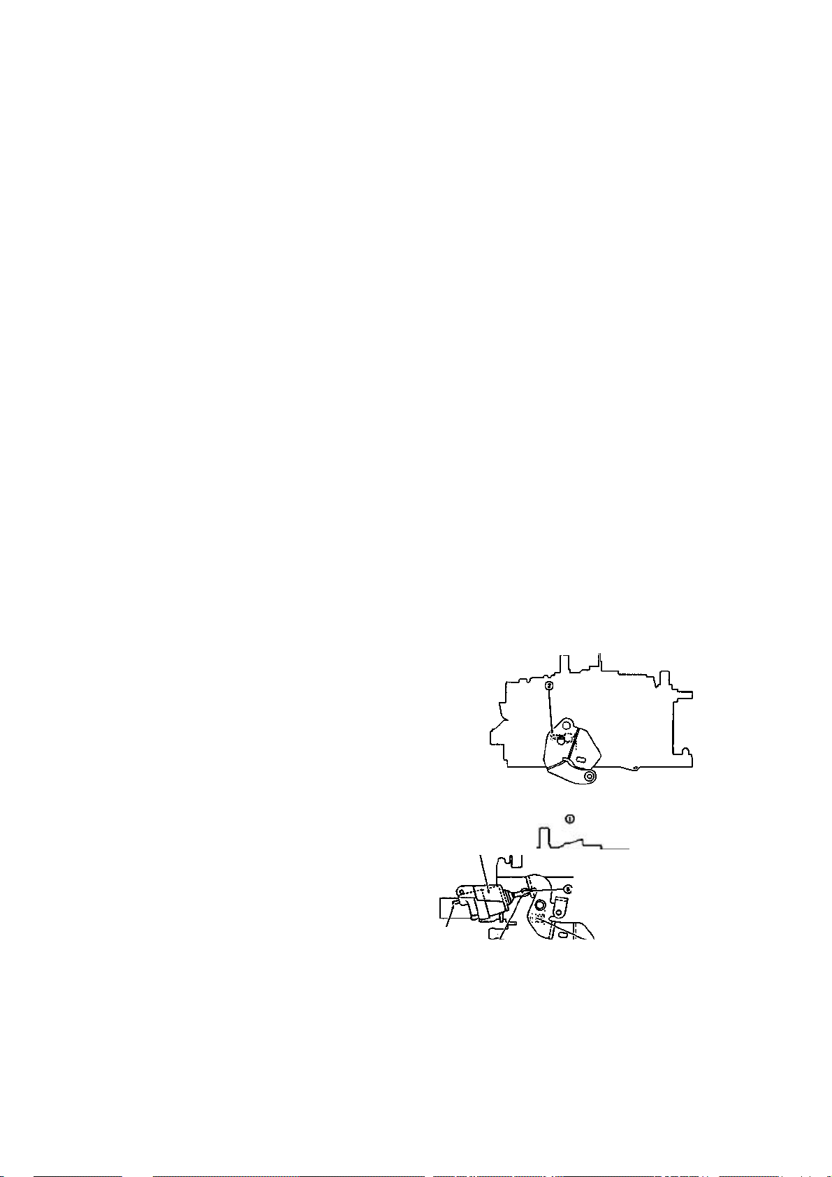
TUNE-UP AND PERFORMANCE MAINTENANCE 55
TURN IDLE SPEED SCREW TO
SPECIFICATIONS
-
A/C OFF
IDLE SPEED ADJUSTMENT
-
WITHOUT SOLE
NOID
y SOLENOID ENERGIZED
-
DRIVE.
M/T IN NEUTRAL
PREPARE VEHICLE FOR ADJUSTMENTS
LEAD AFTER ADJ
USTMENT!
ELECTRICAL
I/ TURN IDLE SPEED SCREW TO
SPECIFICATIONS
-
A/CO*F
5OLENOI
A/C IDLE SPEED ADJUSTMENT
-
WITH SOLENOID
Position the fast idle cam follower on the top
step of the cam and adjust the fast idle to 1300
rpm on manual; 1600 rpm on automatic (in
Park).
454 cu in. V8
1. Shut off the air conditioning. Adjust the
idle stop solenoid screw for 800 rpm on man
ual; 600 rpm on automatic (in Drive).
2. Connect the distributor vaccuum hose
and position the fast idle cam follower on the
top step of the cam and adjust the fast idle to
1600 rpm on manual; 1500 rpm on automatic
(in Park).
1975-76
The same preconditions as for 1973 apply.
1. Turn the air conditioning off.
2. Disconnect the idle speed solenoid.
Turn the idle speed screw to adjust for the
lower of the two idle speeds specified on the
underhood tune-up decal. Adjust automatic
transmission cars in Drive with wheels
blocked; manual transmission cars in Neu
tral.
3. Connect the idle speed solenoid. Open
the throttle to extend the solenoid plunger.
4. Use the solenoid plunger to adjust the
idle speed to the higher of the two speeds on
the underhood tune-up decal.
1977-IDLE SPEED
Run the engine to normal operating temperature, A/C off, vacuum advance line disconnected and plugged, FUEL TANK line at the
canister disconnected. Place the manual
transmission in neutral; automatic transmission in drive. Connect a tachometer to the
engine.
NOTE: Make sure the parking brake is on
and the drive wheels are sufficiently blocked
when placing the transmission in drive.
5. Turn the solenoid screw to higher of the
two idle speeds specified on the underhood
tune-up decal.
6. Reconnect the A/C compressor lead.
1977-IDLE MIXTURE
NOTE: Idle mixture screws have been preset at the factory and capped and should
not require adjustment, however if the need
arises follow the procedure listed below.
1. Set the parking brake and block the
drive wheels.
2. Remove the air cleaner to gain access
to the carburetor, but keep the vacuum hoses
connected.
3. Run the engine to normal operating
temperature with the choke open.
4. Turn the A/C off.
5. Disconnect and plug the vacuum ad
vance hose at the distributor.
6. Check the ignition timing and adjust
as necessary.
7. Using a sharp knife, carefully remove
the plastic caps from the idle mixture screws.
Use extreme caution to avoid bending the
mixture screws.
8. Lightly seat the screws then back out
equally just enough so the engine will run.
9. Place the automatic transmission in
drive or the manual transmission in neutral.
10. Back out each screw (richen) % turn at
/PREPARE VEHICLE FOR ADJUSTMENTS
SET CURB IDLE SPEED TO
Without A/C
1. Turn the idle speed screw to achieve the
rpm specified on the underhood tune-up decal.
With A/C
1. Turn the idle speed screw to the lower
of the two idle speeds specified on the under
hood tune-up decal.
2. Turn the A/C system on.
3. Disconnect the A/C compressor lead at
the compressor.
4. Open the throttle slightly to allow the
solenoid plunger to fully extend.
A/C COMPRESSOR LEAD
DISCONNECTED AT A/C
COMPRESSOR. A/C ON.
A/T TRANSMISSION IN
TURN SOLENOID SCREW TO
ADJUST TO SPECIREO RPM
(RECONNECT A/C COMPRESSOR
©OPEN THRI
1ROTTLE 5UGHTLT TO ALLOW (<? ^X
no PLUNGER TO FULIV EXTEND v—
Idle speed adjustment (1977-80 M4MC)
SET CURB IDLE SPEED TO
JT
I
Page 61

56 TUNE-UP AND PERFORMANCE MAINTENANCE
a time until the maximum idle speed is obtained. Then set the idle speed screw to:
Standard engine (180 hp) M.T.-800 rpm,
A.T.-550 rpm; Optional engine (210 hp) M.T.900 rpm, A.T. (low altitude) 750 rpm, A.T.
(high altitude) 650 rpm.
11. Turn in each screw (lean) Vs turn at a
time until the idle reaches the following rpm:
Standard engine (180 hp)-M.T. -700 rpm,
A.T.-500 rpm. Optional engine (210 hp)-800
rpm, A.T. (low altitude), 600 rpm for A.T.,
high altitude.
12. Reset the idle speed to specification.
13. Reconnect the vacuum hoses and in
stall the air cleaner.
1978-80 IDLE SPEED
This procedure applies only to those models
which DO NOT have the computer controlled emissions system. Vehicles having the
computer system have 13 screws retaining the
air horn of the carburetor; vehicles without
the computer system have 9 screws retaining
the carburetor air horn. Also, computer
equipped vehicles do not have the familiar
vacuum advance unit installed on the distributor, as the spark advance is controlled by
the computer.
CAUTION: // your vehicle has the com-
puter emissions system, DO NOT attempt
to adjust either the idle speed or mixture,
as the fuel system calibration could become
severely upset.
Run the engine to normal operating temperature, A/C off, die purge hose at die vapor canister and the vacuum hose at the EGR
valve disconnected and plugged. Place the
manual transmission is Neutral and the automatic transmission in Drive. NOTE: Make
sure the parking brake is on and the drive
wheels are safely blocked before the
transmission is placed in Drive.
Without A/C
1. Turn the idle speed screw to achieve the
rpm specified on the underhood specifications decal.
With A/C
1. Turn the idle speed screw to the lower
of the two idle speeds listed on the under
hood specifications decal.
2. Turn the air conditioning on.
3. Disconnect the A/C compressor lead at
the compressor (two-wire connector).
4. Open the throttle slightly to allow the
solenoid plunger to extend fully.
5. Turn the solenoid screw to adjust the
engine speed to the higher of the two speeds
listed on the specifications decal under the
hood. Use the higher idle speed, NOT the
fast idle speed specification.
6. Reconnect the A/C compressor lead.
1978-80 IDLE MIXTURE
Changes in the idle systems of these models
make it impossible to properly adjust the
mixture without the use of a propane enrichment system, not available to the general
public.
In some 1978 and all 1979-80 models, the
idle mixture screws are sealed within the
dirotde body of the carburetor. Idle mixture
adjustments should be left to the professional
technician with the proper equipment and
experience.
1981-84 IDLE MIXTURE
Idle speed and mixture are controlled strictly
by the computer emissions system. Do not
attempt to adjust the idle speed or mixture as
these functions are controlled by the computer.
NOTE: For all throttle body injection ad-
justments, see the Fuel Injection section.
Page 62

Engine Rebuilding
UNDERSTANDING THE ENGINE
ELECTRICAL SYSTEM
The engine electrical system can be broken
down into three separate and distinct systems—(1) the starting system; (2) the charging system; (3) the ignition system.
NOTE: See "Troubleshooting" for typical
diagnosis procedures.
Battery and Starting System
The battery is the first link in the chain of
mechanisms which work together to provide
cranking of the automobile engine. In most
modern cars, the battery is a lead-acid electrochemical device consisting of six two-volt
(2 V) subsections connected in series so the
unit is capable of producing approximately 12
V of electrical pressure. Each subsection, or
cell, consists of a series of positive and negative plates held a short distance apart in a solution of sulfuric acid and water. The two
types of plates are of dissimilar metals. This
causes a chemical reaction to be set up, and
it is this reaction which produces current flow
from the battery when its positive and negative terminals are connected to an electrical
appliance such as a lamp or motor. The continued transfer of electrons would eventually
convert the sulfuric acid in the electrolyte to
water, and make the two plates identical in
chemical composition. As electrical energy is
removed from the battery, its voltage output
tends to drop. Thus, measuring battery voltage and battery electrolyte composition are
two ways of checking the ability of the unit to
supply power. During the starting of the engine, electrical energy is removed from the
battery. However, if the charging circuit is in
Engine and
good condition and the operating conditions
are normal, the power removed from the battery will be replaced by the generator (or alternator) which will force electrons back
through the battery, reversing the normal
flow, and restoring the battery to its original
chemical state.
The battery and starting motor are linked
by very heavy electrical cables designed to
minimize resistance to the flow of current.
Generally, the major power supply cable that
leaves the battery goes directly to the starter,
while other electrical system needs are supplied by a smaller cable. During the starter
operation, power flows from the battery to the
starter and is grounded through the car's
frame and the battery's negative ground strap.
The starting motor is a specially designed,
direct current electric motor capable of producing a very great amount of power for its
size. One thing that allows the motor to produce a great deal of power is its tremendous
rotating speed. It drives the engine through
a tiny pinion gear (attached to the starter's
armature), which drives the very large flywheel ring gear at a greatly reduced speed.
Another factor allowing it to produce so much
power is that only intermittent operation is
required of it. Thus, little allowance for air
circulation is required, and the windings can
be built into a very small space.
Hie starter solenoid is a magnetic device
which employs the small current supplied by
the starting switch circuit of the ignition
switch. This magnetic action moves a plunger
which mechanically engages the starter and
electrically closes the heavy switch which
connects it to the battery. The starting switch
circuit consists of the starting switch contained within the ignition switch, a transmission neutral safety switch or clutch pedal
Page 63

58 ENGINE AND ENGINE REBUILDING
switch, and the wiring necessary to connect
these with the starter solenoid or relay.
A pinion, which is a small gear, is mounted
to a one-way drive clutch. This clutch is
splined to the starter armature shaft. When
the ignition switch is moved to the "start" position, the solenoid plunger slides the pinion
toward the flywheel ring gear via a collar and
spring. If the teeth on the pinion and flywheel match properly, the pinion will engage
the flywheel immediately. If the gear teeth
butt one another, the spring will be compressed and will force the gears to mesh as
soon as the starter turns far enough to allow
them to do so. As the solenoid plunger
reaches the end of its travel, it closes the contacts that connect the battery and starter and
then the engine is cranked.
As soon as the engine starts, the flywheel
ring gear begins turning fast enough to drive
the pinion at an extremely high rate of speed.
At mis point, the one-way clutch begins allowing the pinion to spin fester than the
starter shaft so that the starter will not operate at excessive speed. When the ignition
switch is released from the starter position,
the solenoid is de-energized, and a spring
contained within the solenoid assembly pulls
the gear out of mesh and interrupts the current flow to the starter.
The Charging System
The automobile charging system provides
electrical power for operation of the vehicle's
ignition and starting systems and all the electrical accessories. The battery serves as an
electrical surge or storage tank, storing (in
chemical form) the energy originally produced by the engine-driven generator. The
system also provides a means of regulating
generator output to protect the battery from
being overcharged and to avoid excessive
voltage to the accessories.
The storage battery is a chemical device incorporating parallel lead plates in a tank containing a sulfuric acid-water solution. Adjacent plates are slightly dissimilar, and the
chemical reaction of the two dissimilar plates
produces electrical energy when the battery
is connected to a load such as the starter motor. The chemical reaction is reversible, so
that when the generator is producing a voltage (electrical pressure) greater than that
produced by the battery, electricity is forced
into the battery, and the battery is returned
to its fully charged state.
The vehicle's generator is driven mechanically, through V belts, by the engine crankshaft. It consists of two coils of fine wire, one
stationary (the "stator"), and one movable (the
''rotor"). The rotor may also be known as the
"armature," and consists of fine wire wrapped
around an iron core which is mounted on a
shaft. The electricity which flows through the
two coils of wire (provided initially by the
battery in some cases) creates an intense
magnetic field around both rotor and stator,
and the interaction between the two fields
creates voltage, allowing the generator to
power the accessories and charge the battery.
There are two types of generators; the earlier is the direct current (DC) type. The current produced by the DC generator is generated in the armature and carried off the
spinning armature by stationary brushes contacting the commutator. The commutator is a
series of smooth metal contact plates on the
end of the armature. The commutator plates,
which are separated from one another by a
very short gap, are connected to die armature circuits so that current will flow in one
direction only in the wires carrying the generator output. The generator stator consists
of two stationary coils of wire which draw
some of the output current of the generator
to form a powerful magnetic field and create
the interaction of fields which generates the
voltage. The generator field is wired in series
with the regulator.
Newer automobiles use alternating current
generators or "alternators" because they are
more efficient, can be rotated at higher
speeds, and have fewer brush problems. In
an alternator, the field rotates while all the
current produced passes only through the
stator windings. The brushes bear against
continuous slip rings rather than a commutator. This causes the current produced to periodically reverse the direction of its flow.
Diodes (electrical one-way switches) block the
flow of current from traveling in the wrong
direction. A series of diodes is wired together
to permit the alternating flow of the stator to
be converted to a pulsating, but unidirectional flow at the alternator output. The alternator's field is wired in series with the voltage regulator.
The regulator consists of several circuits.
Each circuit has a core, or magnetic coil of
wire, which operates a switch. Each switch is
connected to ground through one or more resistors. The coil of wire responds directly to
system voltage. When the voltage reaches the
Page 64

ENGINE AND ENGINE REBUILDING 59
required level, the magnetic field created by
the winding of wire closes the switch and inserts a resistance into the generator field circuit, thus reducing the output. The contacts
of the switch cycle open and close many times
each second to precisely control voltage.
While alternators are self-limiting as far as
maximum current is concerned, DC generators employ a current regulating circuit which
responds directly to the total amount of current flowing through the generator circuit
rather than to the output voltage. The current regulator is similar to the voltage regulator except that all system current must flow
through the energizing coil on its way to the
various accessories.
SAFETY PRECAUTIONS
Observing these precautions will ensure safe
handling of the electrical system components, and will avoid damage to the vehicle's
electrical system:
1. Observing these precautions will en
sure safe handling of the electrical system
components, and will avoid damage to the
vehicle's electrical system:
2. Be absolutely sure of the polarity of a
booster battery before making connections.
Connect the cables positive to positive, and
negative to negative. Connect positive cables
first and then make the last connection to a
ground on the body of the booster vehicle so
that arcing cannot ignite hydrogen gas that
may have accumulated near the battery. Even
momentary connection of a booster battery
with the polarity reserved will damage alter
nator diodes.
3. Disconnect both vehicle battery ca
bles before attempting to charge a battery.
4. Never ground the alternator or gener
ator output or battery terminal. Be cautious
when using metal tools around a battery to
avoid creating a short circuit between the
terminals.
5. Never ground the field circuit be
tween the alternator and regulator.
6. Never run an alternator or generator
without load unless the field circuit is discon
nected.
7. Never attempt to polarize an alterna
tor.
8. Keep the regulator cover in place when
taking voltage and current limiter readings.
9. Use insulated tools when adjusting the
regulator.
10. Whenever DC generator-to-regulator
wires have been disconnected, the generator
must be repolarized. To do this with an externally grounded, light duty generator, momentarily place a jumper wire between the
battery terminal and the generator terminal
of the regulator. With an internally grounded
heavy duty unit, disconnect the wire to the
regulator field terminal and touch the regulator battery terminal with it.
11. Never disconnect components with the
ignition ON.
The Conventional Ignition
System
MECHANICAL OPERATION
The distributor is geared to the camshaft of
the engine, and in the case of a Chevrolet V8, is also used to drive the engine oil pump
in addition to its usual "spark sorting" duties.
As the distributor shaft turns, the lobes of the
distributor cam actuate the breaker point set,
causing the points to open and close. The
points are attached to the breaker plate, which
on models using a vacuum advance system,
is capable of rotating around the distributor
shaft a small amount. This rotation of the
breaker plate changes the relationship between the distributor shaft and the point set.
The change in this relationship alters the time
at which the points open, thereby changing
the ignition timing. The amount of the ignition timing change, in degrees, is controlled
by the vacuum advance diaphragm which
senses the engine load through engine vacuum changes. The vacuum advance diaphragm is controlled by either "ported" or
"manifold" vacuum. A ported vacuum source
is one that is located above the throttle plates
of the carburetor, whereas a manifold vacuum source is located below the carburetor
throttle pktes (or attached to a fitting directly
on the intake manifold). At a given open
throttle position, the vacuum signal to the
distributor will be basically the same, whether
it is from a ported or manifold vacuum source.
During idle, however, manifold vacuum is
high; ported is low. As vacuum to the advance unit is increased, the amount of degrees which the unit moves (advances) the
breaker plate is also increased, and vice-versa
(retard). It is because of this that you must
disconnect the vacuum advance unit before
adjusting the initial timing on engines which
have a manifold vacuum source to the distributor. The most important function of the vacuum advance is to advance the ignition timing during cruise conditions for improved fuel
Page 65

60 ENGINE AND ENGINE REBUILDING
economy. As engine load increases, engine
vacuum drops, which allows the ignition timing to retard, thereby preventing detonation
due to over-advanced timing. Some special
high performance models such as the 427/L88
do not have vacuum advance systems. Fuel
economy was not designed into such "offroad" engines.
NOTE: Do not remove the vacuum ad-
vance for street usage—fuel economy will
suffer, along with engine performance if not
set-up properly.
Another timing feature of the distributor is
the centrifugal advance mechanism. This
mechanism alters the ignition timing by rotating the distributor cam (a small amount)
independent of the distributor shaft. Again,
the relationship between the distributor shaft
and the point opening is changed due to this
rotation. The centrifugal advance mechanism
consists basically of two small springs and two
specially shaped weights attached to both the
distributor cam and the shaft. These components are mounted underneath the ignition
rotor. Instead of vacuum, this mechanism uses
engine rpm as a guide for advancing the ignition timing. As engine rpm (and distributor
shaft rpm) increases, the weights are moved
gradually outward (against the spring tension) by centrifugal force. As the weights
move outward, the distributor cam is moved
to a more advanced timing position. When
the engine rpm drops, the springs gradually
pull the weights back to their low-speed position, thereby reducing the amount of tuning advance.
ELECTRICAL OPERATION
The point set, or breaker points as they are
sometimes called, is the switching device of
a conventional ignition system. The "primary" side of the ignition coil is connected to
the battery, through the ignition switch, a resistor, and various wiring. When the ignition
switch is in the "run" position, voltage from
the ignition switch passes through a resistor,
which lowers the battery voltage to the coil
from 12V down to about 6-8V.
NOTE: If this resistor is defective, the full
12V from the battery will quickly burn the
breaker point contacts and shorten the life
of the ignition coil.
When the ignition switch is in the "start"
position, the resistor is bypassed. This provides a full 12V to the ignition system to aid
in starting the engine. Voltage flow after
the resistor (or bypass
wire) is through the primary (low voltage)
windings of the coil, to the breaker point set.
When the points are closed (grounded), a
magnetic field is produced within the primary windings of the ignition coil. When the
points open, the coil voltage no longer has an
easy path to ground. The magnetic field collapses and transfers the voltage from the primary windings (outer) of the coil to the "secondary" windings (inner) of the coil, through
induction. Since the number of secondary
windings in the ignition coil is much greater
than the primary, the voltage is multiplied to
roughly 20-25,000 volts. This high voltage
then travels out of the center tower of the
ignition coil, through the high tension lead
(secondary coil wire) to the center tower of
the distributor cap. The voltage is then distributed by the ignition rotor to the outer terminals of the distributor cap (in the "firing
order"), through the plug wires and finally,
the voltage jumps the gap of the spark plug,
causing ignition of the air/fuel mixture in the
cylinder.
The condenser, which is also attached to
the breaker plate (grounded), acts as a temporary voltage storage unit when the points
are closed. This helps to prevent arcing between the point contacts when the points are
opened. Rapid metal transfer between the
point contacts is indicative of a bad condensor.
The Breakerless Ignition
Systems (Including H.E.I.)
Both the transistorized and H.E.I, systems
operate in basically the same manner as the
conventional ignition system, with the exception of the type of "switching device" used.
As stated previously, the switching device of
a conventional ignition system is the breaker
point set. In the breakerless ignition systems, a toothed iron timer core is mounted
on the distributor shaft. The timer core is
mounted on the distributor shaft. The timer
core rotates inside of an electronic pole piece.
The pole piece has internal teeth (corresponding to those on the timer core) and contains a permanent magnet and pick-up coil
(not to be confused with the ignition coil). The
pole piece senses the magnetic field of the
timer core teeth and sends a signal to the ignition module which electronically "calls the
shots" concerning control of the primary coil
voltage. The ignition coil operates in basically the same manner as a conventional ig-
Page 66

ENGINE AND ENGINE REBUILDING 61
nition coil (though the ignition coils DO NOT
interchange), but is controlled by the timer
core, pole piece, and module; instead of the
breaker points and condenser.
NOTE: H.E.I, ignitions use a condensor,
but it is primarily used for radio interference purposes.
As far as the mechanical advance is concerned, the operation is also basically the
same as a conventional ignition system, with
the exception that the timer core rotates on
the distributor shaft instead of the distributor
cam used in conventional systems. The vacuum advance unit moves the breaker plate in
the same manner as the conventional system,
but the timing changes according to the position of the pole piece instead of the breaker
points.
Appearance wise, the transistorized igni-
tion distributor looks very much like a conventional distributor, with the exception of a
two-wire lead (with a quick-disconnect plug)
coming from the dsitributor. Also, the tran-
sistorized system uses both an externally
mounted ignition coil and an ignition ampli-
fier unit which is finned for heat dissipation.
CAUTION: Do not use a conventional ig-
nition coil in place of an electronic ignition
coil, or vice-versa. Component damage
could result.
The H.E.I, distributor looks nothing like a
conventional distributor. The components of
an H.E.I, distributor are all contained within
the distributor (pole piece, ignition coil,
module, etc.).
Refer to Chapter 11 for detailed H.E.I,
system troubleshooting. None of the electri cal components used in either the transistor ized or H.E.I, systems are adjustable. If a
component is found to be defective, it must
be replaced.
HE/ SYSTEM PRECAUTIONS
Before going on to troubleshooting, it might
be a good idea to take note of the following
precautions:
Timing Light Use
Inductive pick-up timing lights are the best
kind to use if your car is equipped with HEI.
Timing lights which connect between the
spark plug and the spark plug wire occasionally (not always) give false readings.
Spark Plug Wires
The plug wires used with H.E.I, systems are
of a different construction than conventional
wires. When replacing them, make sure you
get the correct wires, since conventional wires
won't carry the voltage. Also, handle them
carefully to avoid cracking or splitting them
and never pierce them.
Tachometer Use
Not all tachometers will operate or indicate
correctly when used on a H.E.I, system.
While some tachometers may give a reading,
this does not necessarily mean the reading is
correct. In addition, some tachometers hook
up differently from others. If you can't figure
out whether or not your tachometer will work
on your car, check with the tachometer manufacturer. Dwell readings, of course, have no
significance at all.
H.E.I. System Testers
Instruments designed specifically for testing
H.E.I, systems are available from several tool
manufacturers. Some of these will even test
the module itself. However, the tests given
in the following section will require only an
ohmmeter and a voltmeter.
ENGINE ELECTRICAL
Distributor
REMOVAL
Conventional and Transistorized Systems
1. Rotate the engine until the timing mark
on the crankshaft balancer is aligned with the
top dead center mark (TDC or "0") on the
timing tab scale. Remove the air cleaner as
sembly.
2. Remove the ignition shielding and dis
connect the secondary (high tension) coil wire.
3. Release the distributor cap hold-down
screws (push down and turn counterclock
wise). Raise the distributor cap off of the dis
tributor and check that the firing tip of the
rotor is pointed at the #1 terminal of the dis
tributor cap. If it is not; turn the engine one
full revolution and again align the timing
marks as previously stated. Recheck the rotor
position.
4. Pull the plug wires out of the locating
looms (if so equipped) and move the cap out
of the way. Leave the plug wires attached to
the cap.
5. Disconnect the battery cables at the
battery.
6. Disconnect the tachometer and fuel
Page 67
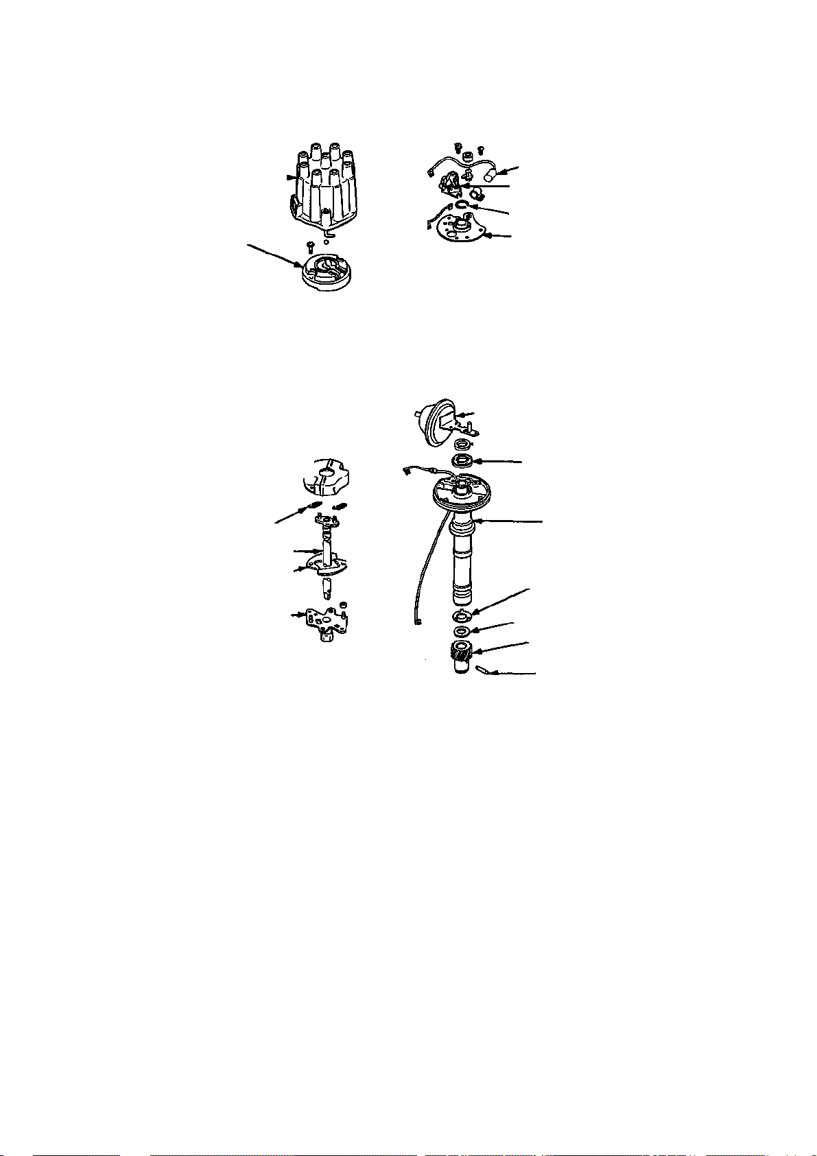
62 ENGINE AND ENGINE REBUILDING
CAP ROTOR
ASSEMBLY
HOUSING
TANGED WASHER
DRIVE GEAR
DRIVE PIN
RADIO FREQUENCY
INTERFERENCE
SHIELD
WEIGHT SPRINGS
MAINSHAFT
ADVANCE WEIGHTS
CAM WEIGHT BASE
CONDENSER
CONTACT
POINT
ASSEMBLY
RETAINING RING
BREAKER PLATE
VACUUM ADVANCE UNIT
0----------------------
FELT WASHER
PLASTIC SEAL
SHIM WASHER
Exploded view of the V8 points-type
injection drive cables from the
distributor, if so equipped.
7. Disconnect the vacuum line from the
distributor vacuum advance unit, if so
equipped.
8. Mark the relationships between the
following items:
a. Rotor firing tip and distributor body
b. distributor body and either the fire
wall or the intake manifold
The combination of these marks will assure
that the distributor gear is properly meshed
with the camshaft and the ignition timing will
be close enough to start the engine after the
distributor is reinstalled.
9. On conventional ignitions, disconnect
the distributor lead from the negative (—)
terminal of the ignition coil. On transistor
ized systems, carefully release and pull apart
the quick-disconnect of the two-wire distrib
utor lead.
10. Remove the distributor hold-down bolt
and plate.
11. Carefully pull the distributor from the
engine. Note the rotation of the rotor as the
distributor is pulled upward, caused by the
angled distributor drive teeth.
distributor
CAUTION: Do not
rotate the engine while
the distributor is
removed.
12. Service the distributor as necessary.
H.E.I. Systems
1. Rotate the engine until the timing mark
on the balancer is aligned with the top dead
center mark (TDC or "O") on the timing tab
scale.
2. Remove the air cleaner assembly and
the ignition shielding.
3. With the ignition switch OFF, discon
nect the feed, module, and tachometer wir
ing from the drivers side of the distributor
cap. Do so by releasing the connector retain
ing tabs and pulling downward on the con
nectors. On 1981—84 models, also disconnect
the four-wire connector installed in the wir
ing from the opposite side of the distributor.
CAUTION: Never allow the "Tach" termi-
nal to touch ground.
4. Locate the locking tabs of the spark plug
wire retaining ring (on the distributor cap).
Move each of the two locking tabs outward to
release the retaining ring. With the plug wires
still attached to the ring, carefully remove the
retaining ring from the distributor cap. Pull
Page 68

NOTE: The following specifications
testing.
Year
1963-64
1965
1966
1967-68
All except fuel injection
Model
Fuel injection
Base engine
Special performance
Fuel injection
Base engine
Special performance
w/transistor ign
F.I. w/transistor ign
300 hp
350 hp
390 hp
350 hp w/transistor ign
390 hp w/transistor ign
425 hp
300 hp
350 hp
390 hp, 400 hp
435 hp
430 hp L88
350 hp w/transistor ign
390 hp, 400 hp
Distributor Specifications
are given in degrees advance at crankshaft speed. Half degrees for distributor machine
Distributor
Part Number
1111024
1111022
1111076
1111069
1111070
1111087
1111060
1111064
1111194
1111438
1111293
1111441
1111294
1111170
1111194
1111438
1111293
1111296
1111295
1111441
1111294
Start
Degrees
@rpm
0@700
0@700
0@750
0@800
0@800
0@750
0@800
0@800
0@900
0@950
0@900
0@900
0@900
0@900
0@900
0@950
0@900
0@900
0@1200
0 @ 900
0@900
Centrifugal Advance
Intermediate
Degrees
@rpm
11 @1600
11 @700
15 @ 1500
NA
NA
15 @ 1500
NA
NA
15 @ 1500
20 @ 1800
8 @ 1250
1 6.5 @ 1400
17 @ 2000
17 @ 2000
15 @ 1500
20 @ 1800
17 @ 2000
NA
18 @ 1900
1 6.5 @ 1400
17 @ 2000
End
Degrees
@rpm
24 @ 4600
24 @ 4600
26 @ 4100
24 @ 2350
24 @ 2350
30 @ 5100
26 @ 2500
26 @ 2500
30 @ 5100
30 @ 4700
32 @ 5000
30 @ 4400
32 @ 5000
32 @ 5000
30 @ 51 00
30 @ 4700
32 @ 5000
30 @ 3800
30 @ 5000
30 @ 4400
32 @ 5000
0@8
0@4
0@4
0@4
0@4
0@4
0@4
0@6
0@8
0@7
0@8
0@7
0@7
0@6
0@8
0@7
0@8
— —
0@8
0@7
Start
Degrees @
In. Hg
0@8
Vacuum Advance
Degrees @
in. Hg
1 6.5 @ 8.2
1 6.5 @ 8.2
1 6.5 @ 8.2
1 6.5 @ 8.2
15@12
End
15 @ 15.5
15 @ 15.5
1 6.5 @ 8.2
1 6.5 @ 8.2
15 @ 15.5
12@12
15 @ 15.5
12@12
12@12
15@12
15 @ 15.5
12@12
15 @ 15.5
15 @ 15.5
12@12
m
g
z rn
> z
D
m
z rn
30
m
c
6
z
Q
CD
Page 69

o
NOTE:
The following specifications
testing.
>
Year Model
1969
1970
1971
1972
1973
300 hp 1111490
350 hp 1111493
390 hp, 400 hp 1111926
435 hp 1111928
430 hp L88 1111927
300 hp 1111490
350 hp 1111493
370 hp 1111491
390 hp 1111464
460 hp 1112026
270 hp 1112050
330 hp 1112038
365 hp 1112051
425 hp w/manual trans 1112076
425 hp w/auto trans 1112053
200 hp 1112050
255 hp 1112101
270 hp 1112051
190 hp 1112098
250 hp 1112150
Distributor Specifications (cont.)
are given in degrees advance at crankshaft speed. Half degrees for distributor machine
Distributor
Part Number
Start
Degrees
@rpm
0@900 15 @ 1500
0@1000 10 @ 1700
0@900 17 @ 2000
0@900 2 @ 1100
0@1200 16 @ 1900
0@900 15 @ 1500
0@1150 10 @ 1700
0@1000
0@1085 17 @ 21 00
0@1000
0@1335 11 @2400
0@1330 16 @ 2250
0@1145 14 @ 2000
0@1300 25 @ 2350
0@1310 21 @ 2350
0@1335 11 @2400
0@1200 14 @ 2000
0@1145 14 @ 2000
0@1100
0@1200
Centrifugal Advance
Intermediate
Degrees
@rpm
NA
NA
—
—
End
Degrees
@rpm
30 @ 51 00
26 @ 5000
26 @ 3800
30 @ 3800
29 @ 5000
30 @ 5100
26 @ 5000
26 @ 5000
22 @ 3200
21 @ 2300
18 @ 4200
24 @ 5000
22 @ 3000
31 @ 6000
28 @ 5000
18 @ 4200
28 @ 5000
22 @ 3000
14 @ 4200
20 @ 5000
Vacuum Advance
Start
Degrees @
in. Hg
0@8
0@7
0@7
0@8
— —
0@8
0@8
0@8
0@7
0@7
0@8
0@8
0@8
0@7
0@7
0@8
0@8
0@8
0@6
0@6
End
Degrees @
in. Hg
19@17
15@12
12@12
15 @ 15.5
19@17
19@17
15 @ 15.5
12@12
12@12
15 @ 15.5
15 @ 15.5
20@17
12@12
12@12
15 @ 15.5
15 @ 15.5
20@17
15@14
15@12
m
z
z
m
m D
z m
30
m
03
c
g
z D
D
Page 70

8
f in
ENGINE AND ENGINE REBUILDING 65
N
: in
CM
•*
co
© o
oo
© o
oo
© o
oo o
8
a
CO
©
o
•sf
o o
CM ^*
8
co
©
o
o o
CM
©
00
o o
© O
8
8
o o
O
o
CM •O-
•*
©
o
8
CO
O O CO
t
©
8
CO
•*
©
o
o o to •&
©
CM
8
8!
Si Si
8
(O
8
©
o
8
CO
§
8
8
a
•*
©
S)
O O
©
CM
8
©
o
a
a <
i
00
8
CM
8 8
CO
8 8
in
s
8
co
CO
o
00 CM
8
S
x:
o
I
Q.
Q.
x:
S
Q.
x:
§ CM
£ g
D.
x: g
a. in
Q. I
a.
£9 o5
E
8
2
I
Page 71
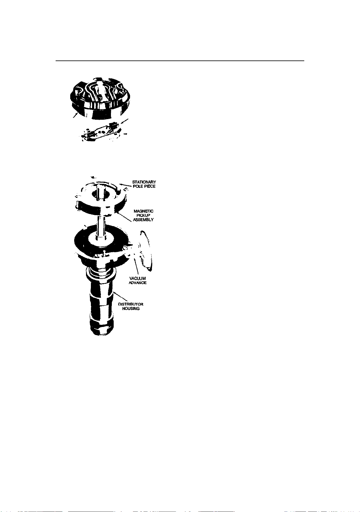
66 ENGINE AND ENGINE REBUILDING
ADVANCE
• POLE PIECE
ROTOR
CENTRIFUGAL
ROTATING
DRIVE ^St> A GEAR - 4® ^
Exploded view of the transistorized distributor
the plug wires out of the locating looms (if so
equipped) and move the ring (with the wires
still attached) out of the way.
5. Release the distributor cap hold-down
screws (push downward and turn counterclockwise) and lift the cap assembly off of the
distributor. Check that the firing tip of the
rotor is pointed at the #1 terminal of the distributor cap; if it is not, rotate the engine one
full revolution and again align the timing
marks. Recheck the position of the rotor.
6. Disconnect the vacuum line from the
distributor vacuum advance unit, if so
equipped.
7. Follow steps 5, 7, 8, and 10-12 of the
previous procedure, in that order to com
plete distributor removal.
INSTALLATION—ENGINE NOT
DISTURBED
1. Clean the distributor and intake man
ifold mating surfaces and check the condition
of the cork gasket. Replace the gasket if it is
damaged.
2. Position the distributor in the engine
without yet engaging it. Align the distributor
housing-to-engine alignment marks which
were made during removal. Position the ro
tor firing tip slightly counterclockwise of the
corresponding distributor housing mark; re
member, the rotor will turn slightly during
installation.
3. Engage the distributor to the engine
by moving it downward. The rotor should turn
to its proper alignment position. If it does not,
lift the distributor enough to disengage the
drive gear, reposition the rotor and lower the
distributor.
4. Install the distributor hold-down plate
and just snug down the bolt.
5. Make sure that the rotor retaining
screws are tight and install the distributor cap.
6. Connect the cables (tach, injection—if
so equipped), wires, and vacuum line (if so
equipped) to the distributor.
7. On conventional ignitions, reconnect
the primary distributor lead to the coil. On
models without H.E.I., reconnect the sec
ondary coil wire.
8. On H.E.I, models, install the plug wire
retaining ring. Press the ring downward until
the two locking tabs engage. Make sure dial
the plug wire terminals are firmly seated on
the distributor cap terminals.
9. Reposition the plug wires into their lo
cating looms, if so equipped.
10. Install the air cleaner and reconnect the
battery cables.
11. Adjust the ignition timing as previ
ously outlined and tighten the distributor
hold-down bolt. Reinstall the ignition shield
ing as necessary.
INSTALLATION—ENGINE DISTURBED
1. The piston of the #1 cylinder must be
on its compression stroke and at the top of its
Page 72
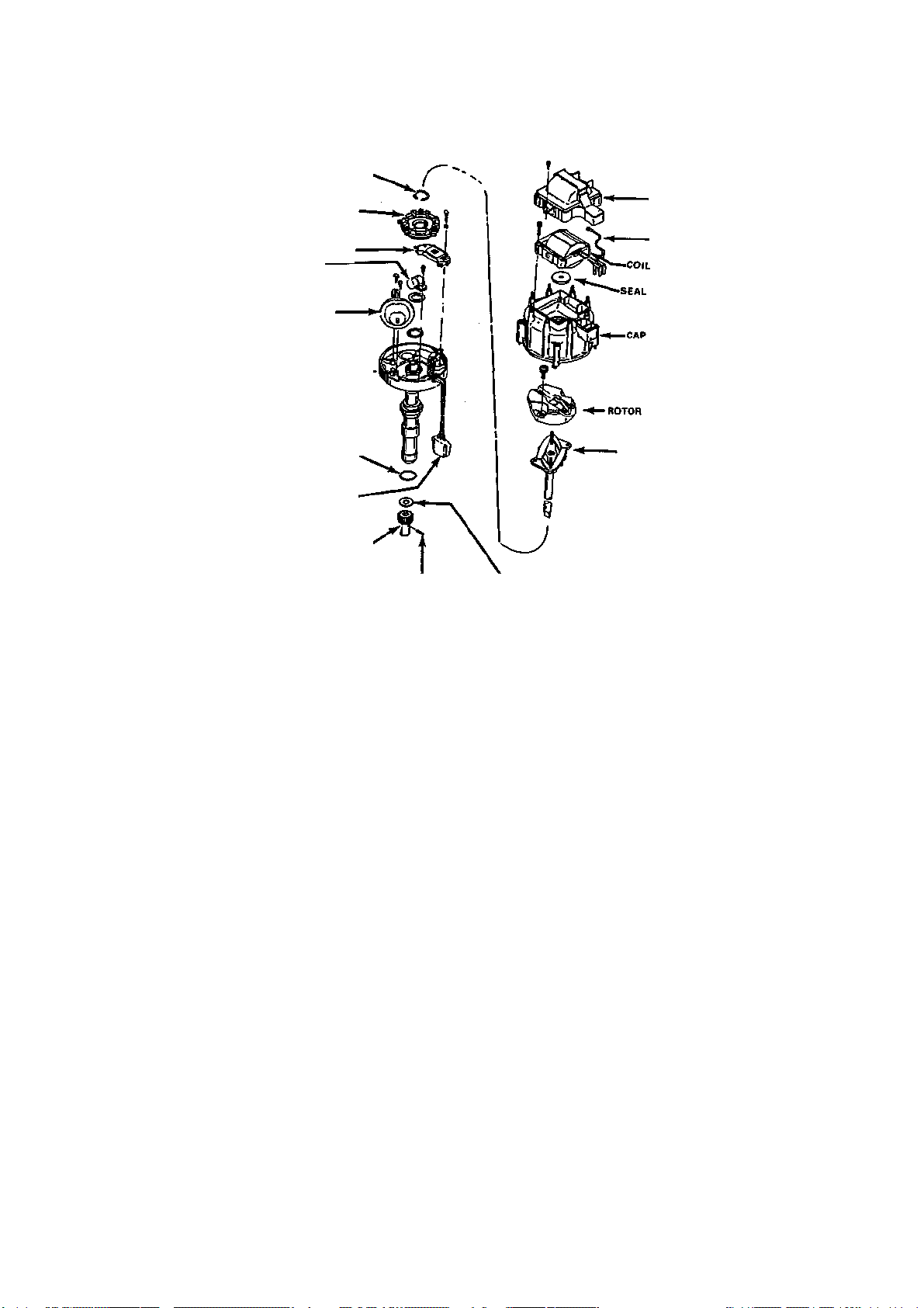
CIRCLIP
COVER
POLE PIECE
LEAD WIRE
AMPLIFIER MODULE
CAPACITOR
VACUUM CONTROL UNIT
HOUSING
ADVANCE SPRING
GASKET
CONNECTOR
GEAR'
ENGINE AND ENGINE REBUILDING 67
Exploded view of the HEI distributor. Engines with the computer emissions system do not have the vacuum
advance unit.
travel (top dead center -TDC) in order to time
the ignition system to the engine. There are
several ways to determine when the piston is
on its compression stroke. In any case, the
#1 spark plug must be removed. The various
methods are as follows:
a. Hold your finger over the spark plug
hole and have an assistant turn the engine
over slowly. When you feel compression,
watch the timing marks. Stop turning the
engine over as soon as the timing mark on
the crankshaft balancer is aligned with the
"0" mark on the timing tab scale.
b. Insert a rag into the spark plug hole
(NOT into the cylinder). Turn the engine
over slowly until the rag is blown out of the
hole. Stop cranking the engine when this
happens and check the riming marks. If
necessary, "tap" the ignition key until the
timing mark on the crankshaft balancer is
aligned with the "O" mark on the timing
tab scale.
c. Attach a compression gauge to the
spark plug hole (preferably the screw-in
type; eliminating the need for an assistant).
Position the gauge dial so that it may be
viewed while cranking the engine. Turn the
engine over until the gauge needle reading
PIN
WASHER
increases, indicating compression. Stop
cranking the engine when this happens and
check the timing marks. If necessary, "tap"
the ignition key until the timing mark on
the crankshaft balancer is aligned with the
"O" mark on the timing tab scale. Remove
the compression gauge. NOTE: There are
tools available commercially which screw
into the #1 spark plug hole and register
(more accurately than the above methods)
when top dead center is reached. If one of
these tools is used, follow the tool
manufacturers instructions.
2. Reinstall the #1 spark plug and connect
the plug wire. With the distributor out of the
vehicle and the distributor cap installed, lo
cate the #1 distributor cap terminal and chalk
mark its position on the distributor housing.
Remove the distributor cap.
3. Position the distributor into the engine
block with the:
a. vacuum advance unit in its proper
position (see the Firing Order illustra
tions).
b. firing tip of the rotor pointing to the
mark made during step 2.
4. As the distributor drive gear engages,
the rotor will turn slightly. If the distributor
Page 73
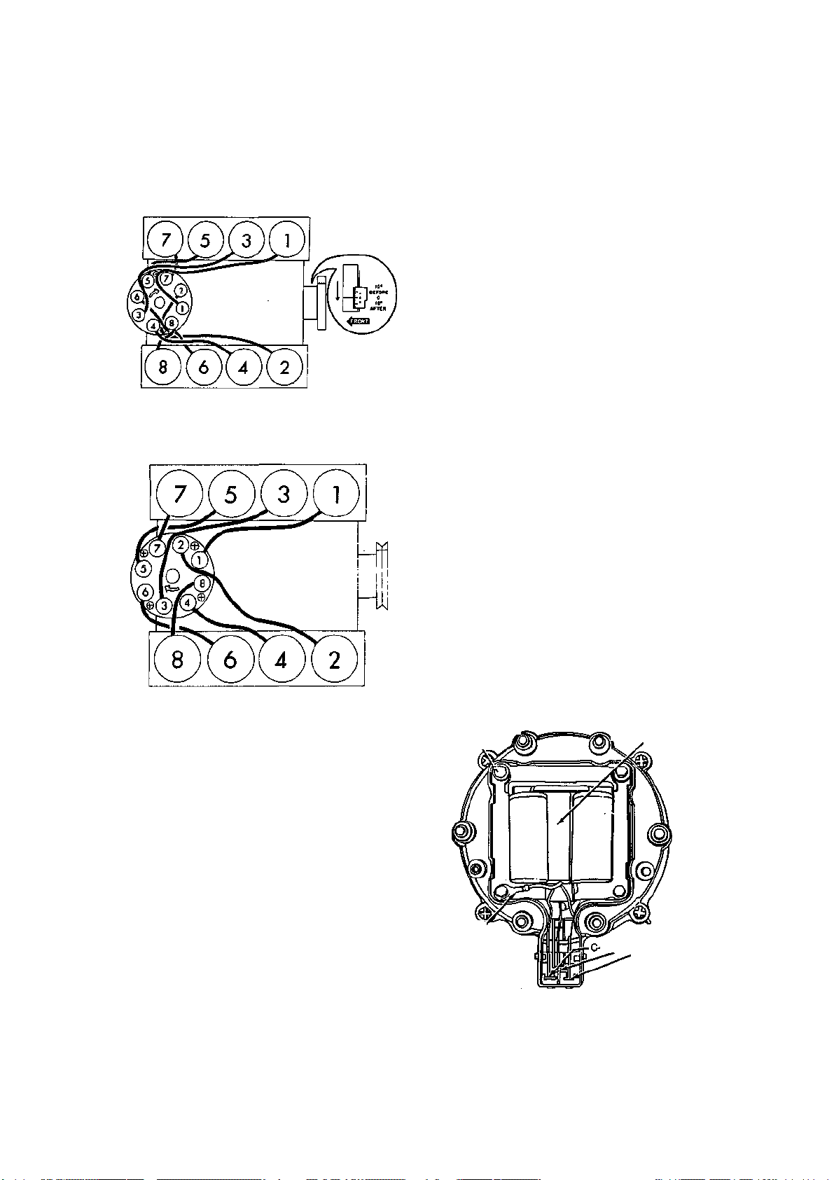
68 ENGINE AND ENGINE REBUILDING
DISTRIBUTOR ROTATION: CLOCKWISE
COIL
GRD. B+
FIRING ORDER
To avoid confusion, replace spark plug wires
one at a time.
1963-74 except HEI
ENGINE FIRING ORDER: 1-8-4-3-6-5-7-2
1974-84 HEI
6. Install the distributor hold-down bolt
and plate. Snug down the retaining bolt.
7. Connect the vacuum advance hose, tach
drive cable, and injection drive cable, on ve
hicles equipped with these items.
8. Connect all wiring and adjust the igni
tion timing as previously outlined.
9. Install the ignition shielding.
H.E.S. COMPONENT REPLACEMENT
Distributor Cap
1. Disconnect the feed, module, and ta
chometer wiring from the drivers side of the
distributor cap. Do so by releasing the wiring
connector retaining tabs and carefully pulling
downward on the connectors.
2. Locate the locking tabs of the spark plug
wire retaining ring (on the distributor cap).
Move each of the two locking tabs outward to
release the retaining ring. With the plug wires
still attached to the ring, pull the ring and
wires off of the distributor cap and move the
assembly out of the way.
3. Release the distributor cap hold-down
screws (push downward and counterclock
wise) and lift the cap assembly off of the dis
tributor.
4. Remove the coil cover from the distrib
utor cap (4 fasteners).
5. Push the spade terminals upward and
out of the distributor cap.
6. Remove the four coil screws and lift the
coil, spring, carbon contact, and rubber
washer out of the distributor cap.
7. Reverse the previous steps to assemble,
using a new cap. Lubricate the rubber washer
with dielectric lubricant during assembly.
housing does not sit properly on the block,
the oil pump shaft is not engaging with the
distributor shaft. In this case, you can do one
of two things:
a. Remove the distributor and turn the
oil pump driveshaft with a long screw
driver to align the pump driveshaft slot with
the "blade" of the distributor shaft. This is
done strictly by visual approximation.
b. Apply downward pressure on the dis
tributor housing (NOT the rotor) and have
someone "tap" the ignition key to slowly
turn the engine over until the distributor
falls into its proper position. After doing
this, it is recommended that you recheck
the timing by repeating steps 1 and 2.
5. On conventional ignitions, after proper
positioning is assured, turn the distributor
housing so that the points are just opening.
COIL
GROUND
LEAD
COIL
SECONDARY
ATTACHING
Ignition coil mounted in the HEI distributor cap
SCREW (4)
IGNITION
TERMINALS
Page 74
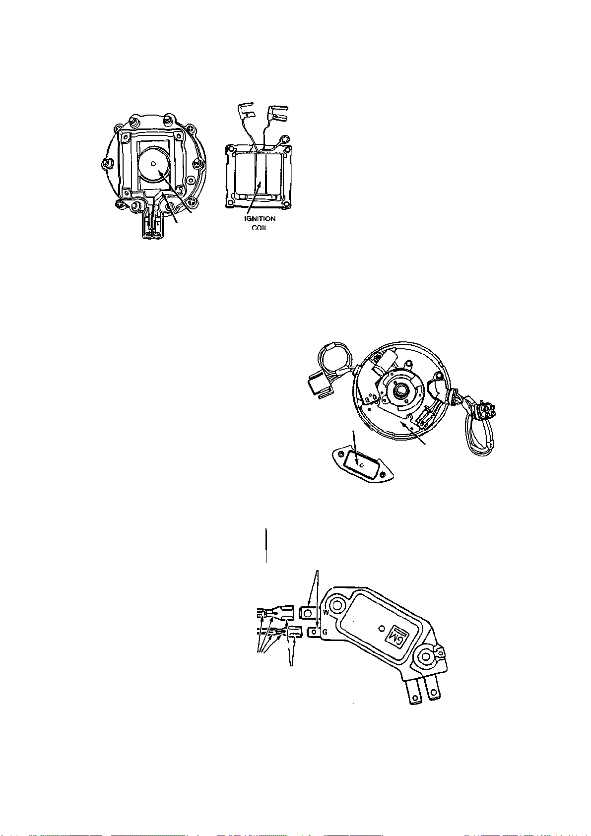
ENGINE AND ENGINE REBUILDING 69
MODULE
Placement of silicone dielectric compound prior
to HEI module installation
—
see text
PUT VASELINE ON
BLADE TERMINALS
GOOD CONNECTIONS ARE ESSENTIAL
SEAL
GROUND
After removing the coil, check the condition of the
arc seal (1981 shown, other years similar)
Ignition Coil
CONNECTOR
Perform steps 1, 2, 4, 5, and 6 of the previous
distributor cap replacment procedure. Install
the new coil, being sure to use the dielectric
compound supplied with most coils to lubricate the rubber washer.
Ignition Rotor
Remove the distributor cap as previously
outlined. Loosen the rotor retaining screws
(most screws will stay attached to the rotor)
and lift the rotor off of the mainshaft assembly. During installation, note the locations of
the different locating "dowels" (2) on the underside of the rotor. These dowels help to
prevent incorrect rotor installation by allowing the rotor to be installed in only one way.
Vacuum Advance Unit (if so equipped)
1. Remoy/e the distributor cap and rotor as
previously outlined.
2. Disconnect the hose from the vacuum
advance unit.
3. Remove the two vacuum advance unit
retaining screws and pull the unit outward.
4. Rotate the unit to disengage the oper
ating rod from the distributor.
5. Reverse the previous steps to install.
Module
1. Remove the distributor cap and rotor as
previously outlined.
2. Carefully disconnect the wiring from the
module.
3. Remove the two module retaining
screws and lift the module out of the distrib
utor housing.
4. Apply a light coating of silicone dielec
tric compound to the distributor housing in
the module mounting area before installing
the new module. The silicone compound is
used to transfer heat from the module to the
APPLY
SILICONE
LUBRICANT
HERE
EXTEND RETAINING TABS TO BE SURE OF POSITIVE LOCK IN CONNECTOR
WHITE WIRE
/"
CONNECTOR REMOVED
GREEN WIRE
A
(SOLDER CLIP TO WIRE)
--------
(SQUEEZE COIL TERMINALS)
Proper HEI module electrical connections
Page 75

70 ENGINE AND ENGINE REBUILDING
distributor housing. If the compound is not
used, the module will overheat, causing failure of the ignition system.
NOTE: Silicone compounds are available
strictly for this purpose—DO NOT use a
regular silicone lubricant or sealer.
5. Install the new module, using the ac
companying illustration as a guide to estab
lish the best possible module connections.
NOTE: Many H.E.I, failures have been at-
tributed to poor module connections. Inspect the wires, terminals, and connectors
for damage and follow tthe accompanying
illustration.
6. Install the rotor and distributor cap as
previously outlined.
NOTE: Items previously listed are the only
items of the H.E.I, distributor which are
serviceable with the distributor installed.
Other services will require distributor removal and disassembly.
DISASSEMBLY
Conventional Systems
1. Remove the distributor cap and the
rotor.
2. Remove the two-piece radio interfer
ence shield (2 fasteners), if so equipped.
3. Remove the centrifugal advance
springs and weights.
4. Drive the roll pin out of the distribu
tor gear using a drift no larger than die roll
pin.
5. Slide the distributor gear off of the shaft
and remove the spacers and washers (note
their arrangement for reinstaUation).
6. Remove the tachometer drive gear.
7. Inspect the distributor shaft for burrs
in the gear mounting area. If there are any
burrs or nicks, carefully smooth them with a
fine file. This should be done to prevent
bushing damage as the distributor shaft is
withdrawn from the housing.
8. Slide the distributor shaft assembly out
of the housing.
9. Remove the vacuum advance unit (2
screws).
10. Carefully remove the breaker plate re
taining ring and lift the breaker plate off of
the distributor housing. DO NOT disassem
ble the breaker plate any further.
11. Remove the point set, condenser, and
the condenser mounting bracket from the
breaker pkte. Remove the washer and seal
from beneath the breaker plate.
Transistorized Systems
1. Remove the distributor cap and the
rotor.
2. Remove the centrifugal advance
springs and weights.
3. Remove the tachometer drive gear.
4. Support the distributor gear (to pre
vent damage to the magnetic pickup assem
bly) and drive the roll pin out of the gear,
using a drift no larger than the roll pin.
5. Slide the distributor gear and washer
off of the distributor shaft.
6. Inspect the distributor shaft for burrs
in the gear mounting area. If there are any
burrs or nicks, carefully smooth them with a
fine file. This should be done to prevent
bushing damage as the distributor shaft is
withdrawn from the housing.
7. Remove the centrifugal advance weight
support and timer core from the distributor
shaft.
8. Disconnect the pickup coil lead con
nector.
9. Remove the retaining ring which se
cures the magnetic pickup assembly to the
distributor housing.
10. Remove the entire magnetic pickup
assembly from the distributor housing. DO
NOT remove the three screws which secure
the stationary pole piece to the pickup as
sembly.
11. Remove the washer and felt pad from
the pickup mounting.
12. Remove the vacuum advance unit.
H.E.I. Systems
1. Remove the distributor cap assembly
and rotor as previously outlined.
2. Remove the centrifugal advance
springs and weights from the mainshaft, if so
equipped.
3. Drive out the distributor gear roll pin
using a drift.
4. Remove the distributor gear and
washers. Note the location of the washers so
that they may be reinstalled properly.
5. Slide the distributor shaft out of the
housing.
6. Disconnect the electrical leads from the
module and remove the module. Also re
move the capacitor.
7. If the internal teeth of the pickup as
sembly are fully exposed; remove the pickup
retaining ring and remove the pickup assem
bly from the distributor housing (Do not re
move the three screws from the pickup as-
Page 76
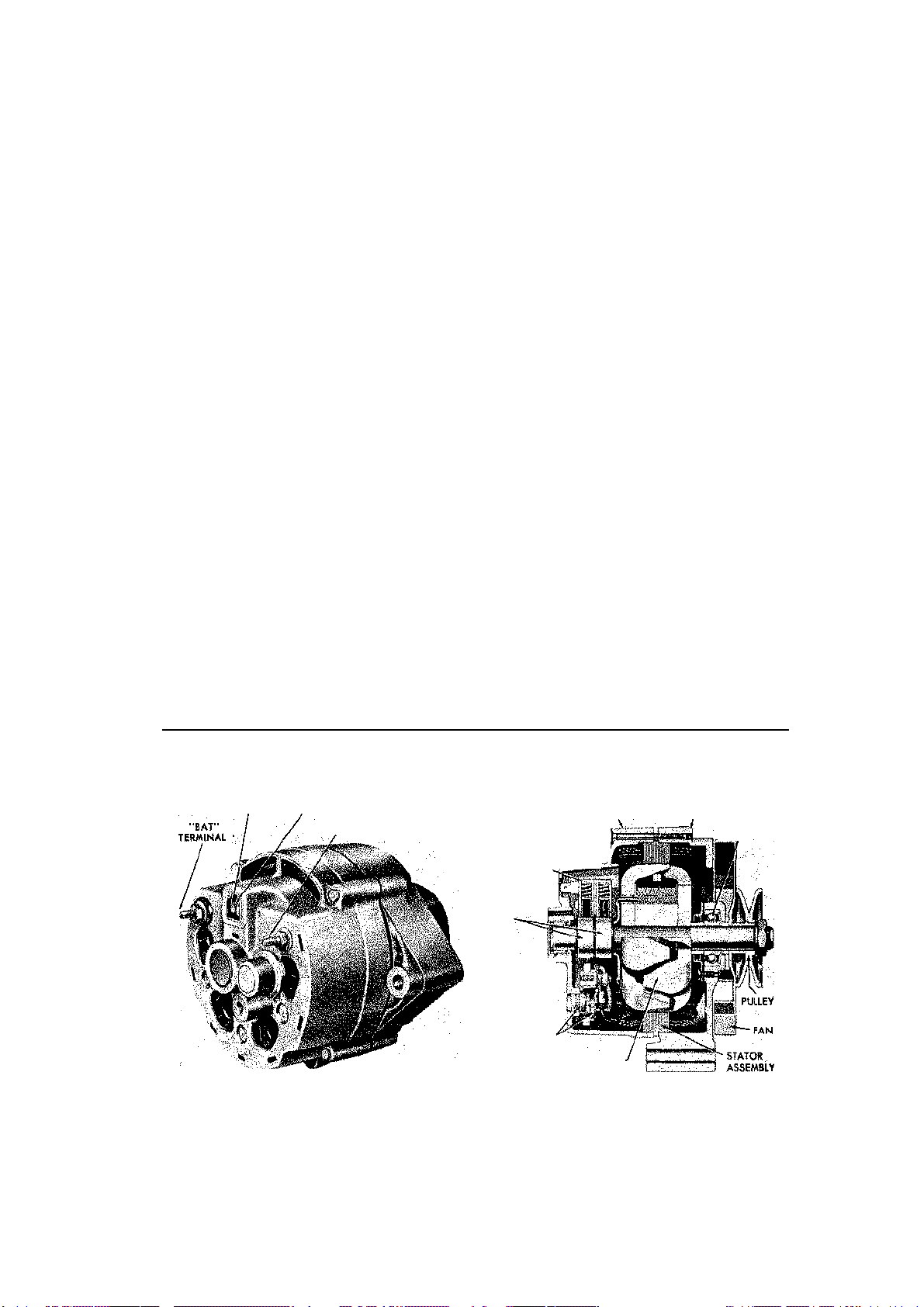
ENGINE AND ENGINE REBUILDING 71
THRU
sembly). If the internal teeth of the pickup
are not fully exposed; remove the magnetic
shield from the pickup assembly (three attaching screws). Remove the pickup assembly retaining ring and remove the pickup
components (magnet, pole piece, pickup coil).
8. Remove the vacuum advance unit, if so
equipped.
ASSEMBLY
Assembly of the distributor is the reverse of
its respective disassembly procedure.
When assembling the distributor, be sure
to lubricate the distributor shaft bushings with
a few drops of engine oil. Also be sure that
the distributor shaft turns freely after it is installed. On conventional, point-type distributors, it is easier to install and gap the points
while the distributor is removed.
On H.E.I, systems, apply a light coating of
silicone dielectric compound to the distributor housing in the module mounting area before installing the module. The silicone compound is used to transfer heat from the
module to the distributor housing. If the
compound is not used, the module will overheat, causing failure of the ignition system.
NOTE: Silicone compounds are available
strictly for this purpose—DO NOT use a
regular silicone lubricant or sealer. Refer to
the previous middle replacement procedure
for additional module installation
information.
Alternator
The alternating current generator (alternator)
supplies a continuous amount of electrical
energy at all engine speeds to keep the battery fully charged. The Corvette, as all other
GM vehicles, uses a Delcotron alternator.
Delcotron is a trade name of the Delco-designed alternator.
The alternator consists of four main assemblies: drive (pulley) end frame, slip ring (rear)
end frame, stator, and rotor. The drive end
frame houses a ball bearing which is used to
support the front of the rotor and is large
enough to withstand the side loads imposed
on the rotor by the alternator belt. The slip
ring end frame uses a small roller bearing
which is used to support the rear of the rotor
(The "perforated case" Delcotron uses a ball
bearing in the rear, also). These bearings are
lubricated during their assembly and need no
additional lubrication. If you replace the
bearings, try to obtain a fully sealed bearing
for the front, to further increase bearing life.
The stator has a laminated core which is
attached to the frame of the alternator. On
"perforated case" models, the stator is serviced with the main case. A large number of
windings cover the inside diameter of the stator, and it is within this circle that the rotor
turns. Current passes from two brushes
through the slip rings (of the rotor) and finally
to the field coils which are wound in a manner concentric to the rotor shaft.
RELAY TERMINAL / »
Externally regulated Delcotron—except "perforated case" models
" TERMINAL
F
"ORD" TERMINAL
BRUSH AND gOLT -*
TERMINAL ASSEMBtY
SUP RINGS
BEARING-/
DIODES
SUP RING DRIVE END
BEARING
ROTOR
END FRAME FRAME
Page 77
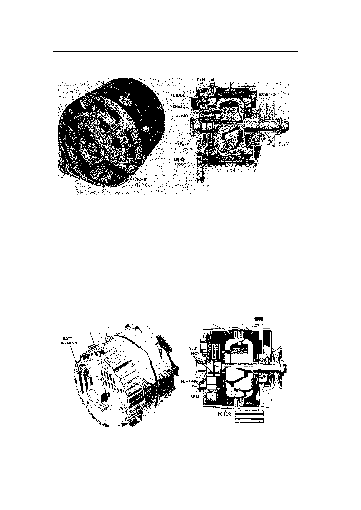
72 ENGINE AND ENGINE REBUILDING
FAN
RESERVOIR
WINDING •
-
"
RELAY
SUP RING
DRIVE
TERMINAL
BEARING
ASSEMBLY
"BATT"
ROTOR
PUUEV
GREASE
FIELD
TERMINAL
Externally regulated, "perforated case" Delcotron
Both the internally and externally regulated Delcotrons use positive and negative
diodes. These diodes are electrical chedk
valves, meaning that they will allow current
to pass freely in only one direction. The
diodes perform the function of changing the
alternating current (AC) developed within the
stator windings to direct current (DC) which
can be used by the 12VDC system. In the
NO. i
NO, 1
TERMINAL
',. S1A10R afitu.
l
7S
externally regulated Delcotron (except the
"perforated case" models), the negative diodes
(3) are pressed into die slip ring end frame;
the positive diodes (3) are pressed into an
electrically insulated heat sink attached to the
slip ring end frame. The diodes used in the
"perforated case" Delcotron are pressed into
removable heat sinks. The grounded heat sink
contains the negative diodes; the insulated
END FRAME END FRAME |
STATOR
Internally regulated Delcotron
Page 78

ENGINE AND ENGINE REBUILDING 73
contains the positive. InternaDy regulated
Delcotrons use a different type of diode ar-
rangement. In these models, the negative
diodes are permanently mounted in a rec-
tifier bridge assembly. The rectifier bridge
utilizes a finned aluminum heat sink for
efficient diode cooling, and is mounted inside
the slip ring end frame. A positive diode trio
is used instead of separately mounted posi-
tive diodes. If a negative diode of the rectifier
bridge fails, the rectifier bridge assembly
must be replaced. Also, the positive diode
trio can only be replaced as a unit.
Generally, internally and externally regulated alternators can easily be distinguished
by the type of plug-in connector which is used
at the alternator. External regulator models
use a connector having two side-by-side vertical spade terminals, whereas the internal
regulator type uses a connector having two
side-by-side horizontal spade terminals. All
"perforated case" Delcotrons use external
voltage regulators.
Adjustments can be made to the external
type of regulator (covered later in this section). The internally mounted voltage regulator is non-adjustable—if it is defective, it
must be replaced.
ALTERNATOR PRECAUTIONS
To prevent damage to the alternator and regulator, the following precautions should be
taken when working with the electrical system.
1. Never reverse the battery connec
tions.
2. Booster batteries for starting must be
connected properly—positive-to-positive and
negative-to-negative.
3. Disconnect the battery cables before
using a fast charger; the charger has a ten
dency to force current through the diodes in
the opposite direction for which they were
designed. This burns out the diodes.
4. Never use a fast charger as a booster
for starting the vehicle.
5. Never disconnect the voltage regula
tor while the engine is running.
6. Avoid long soldering times when re
placing diodes or transistors. Prolonged heat
is damaging to AC generators.
7. Do not use test lamps of more than 12
volts (V) for checking diode continuity.
8. Do not short across or ground any of
the terminals on the AC generator.
9. The polarity of the battery, generator,
and regulator must be matched and con-
sidered before making any electrical connections within the system.
10. Never operate the alternator on an
open circuit. Make sure that all connections
within the circuit are clean and tight.
11. Disconnect the battery terminals when
performing any service on the electrical sys
tem. This will eliminate the possibility of ac
cidental reversal of polarity.
12. Disconnect the battery ground cable if
arc welding is to be done on any part of the
car.
EXTERNALLY REGULATED ON-CAR
CHARGING SYSTEM TESTS
isolation Checks
These are quick checks that will allow the
tester to isolate the general source of charging circuit difficulty in either the alternator,
regulator, or wiring harness. Once the defective component has been singled out, further
checks and repairs may be made using the
procedures given in the alternator or regulator sections. Make these checks after looking
for obvious problems such as a weak battery
or loose fan belt.
Start the engine and bring the idle to between 1500-2000 rpm. Turn off all accessories, lights, radio, etc., and then disconnect
the battery ground cable. If the engine stops,
it is safe to assume that the alternator is at
fault. If, however, the engine continues to
operate, the problem lies with either the regulator or wiring harness.
Having eliminated the alternator from suspicion, the next step is to isolate the regulator
from the harness and the easiest way is to
substitute a known component. Remove the
push-on wiring connector from the regulator
and insert a regulator that is known to be good
into the circuit, remembering to ground the
regulator to the car. Idle the engine, remove
the battery cable, and check the ammeter. If
it indicates a discharge condition, then the
possible problem is an open resistor or a
shorted, positive diode. If the ammeter continues to indicate a charge, then it is the regulator that is defective.
Alternator Tests
Prepare the alternator for testing by disconnecting the battery ground terminal, the BAT,
light relay, field, and GRD leads from the alternator terminals.
Check the positive diodes by connecting an
ohmmeter between the R (or light relay) and
Page 79
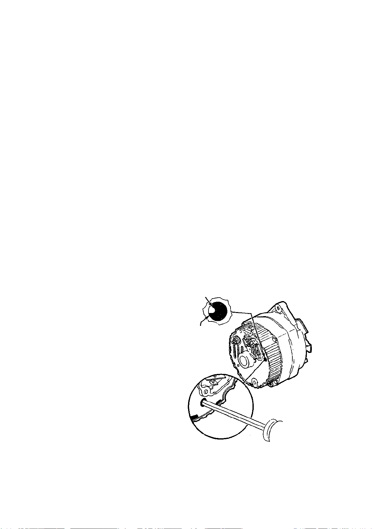
74 ENGINE AND ENGINE REBUILDING
END
HOLE
Ground this tab to test the alternator voltage out
-
BAT terminals, and noting the lowest range
on the ohmmeter scale. It should indicate
very low resistance. Reversing the connections should result in an infinitely high resistance indication.
If the ohmmeter reads low or high in both
directions, the diodes, are defective. A low
reading could also indicate a grounded stator.
To test for an open field, connect the
ohmmeter between the F (or Field) and GRD
terminals and check the low range scale for a
reading between 7 and 20 ohms. A zero indication or one of excessively high resistance
suggests a faulty alternator.
NOTE: The 17SI alternator used on the
1984 Corvette uses delta stator windings and
cannot be checked for an open circuit.
Field Relay Tests
Fasten one voltmeter lead to the no. two regulator terminal and ground the other lead to
the regulator. Idle the engine between 1500
and 2000 rpm. If the GEN light still burns,
and a volt reading of 3.5 to 6.5 is present,
then the regulator field relay is faulty.
Accessory Circuit Resistance Tests
A resistor is connected to the ACC terminal
ignition switch. To check for an open resistor, connect the voltmeter to the no. 4 connection of the regulator and ground the other
voltmeter lead to the regulator. A zero reading, with the ignition switch turned to the
ACC notch, indicates an open resistor. The
resistance wire is an integral part of the ignition harness and carries a rating minimum of
10 ohms, 6.25 watts. The wire is not solderable and must be crimp-connected.
speed and adjust the carbon pile to obtain
maximum alternator output as indicated on
the ammeter. If output is within 10% of rated
output as stamped on the alternator frame,
alternator is O.K. If output is not within
specifications, ground the alternator field by
inserting a screwdriver into the test hole in
the end frame. If output now is within 10%
of rating, replace the voltage regulator; if still
not within specifications, check field winding, diode trio, rectifier bridge and stator, as
described later.
Low Charging Rate Diagnosis
1. After battery condition, drive belt ten
sion, and wiring terminals and connections
have been checked, charge the battery fully
and perform the following test:
2. Connect a test voltmeter between the
alternator BAT, terminal and ground, igni
tion switch on. Connect the voltmeter in turn
to alternator terminals No. 1 and No. 2, the
other voltmeter lead being grounded as be
fore. A zero reading indicates an open circuit
between the battery and each connection at
the alternator. If this test discloses no faults
in the wiring, proceed to Step 3.
3. Connect the test voltmeter to the alter
nator BAT terminal (the other test lead to
INSERT SCREWDRIVER
GROUND TAB TO END
FRAME
TAB
INTERNALLY REGULATED SYSTEM
TESTING
Alternator Output Test
1. Connect a test voltmeter, ammeter, and
a 10-ohm, 6-watt resistor into the charging
circuit. Do not connect the carbon pile to the
battery posts at this time.
2. Increase alternator speed and observe
the voltmeter—if the voltage is uncontrolled
with speed and increases to 16 volts Or more,
check for a grounded brush lead clip as pre
viously covered. If a brush lead clip is not
grounded, the voltage regulator is faulty and
must be replaced.
3. Connect the carbon pile load to the bat
tery terminals.
4. Operate the alternator at moderate
FRAME
put—Internally regulated Delcotron only
Page 80

ENGINE AND ENGINE REBUILDING 75
ground), start the engine and run at 1,5002,000 rpm with all lights and electrical accessories turned on. If the voltmeter reads 12.8
volts or greater, the alternator is good and no
further checks need be made. If the voltmeter reads less than 12.8 volts, ground the field
winding by inserting a screwdriver into the
test hole in the end frame.
CAUTION: Do not force the tab more than
% in. into the end frame.
a. If voltage increases to 13 volts or
more, the regulator unit is defective;
b. If voltage does not increase signifi
cantly, the generator is defective.
High Charging Rate Diagnosis
1. With the battery fully charged, connect
a voltmeter between alternator terminal No.
2 and ground. If the reading is zero, No. 2
circuit from the battery is open.
2. If No. 2 circuit is OK, but an obvious
overcharging condition still exists, proceed as
follows:
a. Remove the alternator and separate
the end frames;
b. Connect a low-range ohmmeter be
tween the brush lead clip arid the end frame
(Test 1), then reverse the connections. If
both readings are zero, either the brush
lead clip is grounded or the regulator is de
fective. A grounded brush lead clip can be
due to damaged insulating sleeve or omis
sion of the insulating washer.
REMOVAL AND INSTALLATION
1. Disconnect the negative battery cable
at the battery; this will prevent damaging the
alternator diodes.
2. Disconnect the wiring from the rear of
the alternator (bolt-on and push-in connec
tors).
3. Loosen the lower alternator bolt and re
move the upper (adjustment) bolt. Slip the
drive belt off of the pulley.
4. Remove the pivot bolt and lift the alter
nator out of its mounting brackets.
5. Installation of the alternator is the re
verse of the previous steps. Adjust the drive
belt to the proper tension.
DISASSEMBLY AND ASSEMBLY
Externally Regulated Type—Except
"Perforated Case" Models
Remove the pulley by positioning a box-end
wrench over the pulley retaining nut and inserting a 5/i6 in. alien wrench in the shaft to
prevent it from turning. Unbolt the retaining
nut and slide it off the pulley. Disconnect the
battery ground strap to prevent diode damage and remove the generator. On the 6.2 in.
perforated case generator, remove the bladeconnector retaining nuts and remove the
connectors. Slip the indicator light relay from
the terminal post, then back out die retaining
screws, and remove the brush holder. Leave
the capacitor attached to the generator. Remove the four, long, case bolts and separate
the end frame and rotor assembly from the
stator assembly. Cover the slip ring and bearing with tape to prevent contamination.
Remove the rotor from the end frame. Extract the retainer plate screws and remove the
retainer plate and the end frame bearing. Remove the three attaching screws and separate
the stator from the end frame. Remove the
heat sink.
Wash all metal parts with the exception of
the stator and rotor assemblies. The rotor slip
rings may be cleaned with 400 grain polishing cloth. It is a good idea to rotate the rotor
while doing this to guard against rubbing flat
spots on the slip rings. Maximum out-of-round
tolerance for sh'p rings is 01001 in. Remove as
little metal as possible when truing on a lathe.
Polish with 400 grain cloth and blow dry. To
assemble the alternator: Attach the slip-ring
end frame to the stator assembly and
position the diode connectors above the
diode, relay, and stator leads. Tighten the
terminal nuts, then slide the front end frame
over the rotor. Slide on the spacer, pulley,
washer, and nut, and torque the shaft to 5060 ft. Ibs. Attach the slip-ring end frame and
stator to the rotor and drive end frame
assembly and insert and tighten the thrubolts.
Externally Regulated Type—"Perforated
Case" Models
1. Mount the alternator in a vise, clamp
ing the drive end mounting flange length
wise.
2. Remove the two screws which secure
the cover to the brush holder and remove the
cover.
3. Remove the nut which retains the in
dicator light wire to the bkde connector post.
Disconnect the wire from the connector post.
4. Remove the two brush holder assem
bly attaching screws and remove the brush
holder.
NOTE: The capacitor lead is connected in-
side the alternator; the capacitor must stay
Page 81

76 ENGINE AND ENGINE REBUILDING
with the alternator to avoid overstressing
the lead wire.
5. Scribe alignment marks to indicate the
relationships between the end frames and the
main base. These components must be prop
erly aligned during assembly.
6. Remove the slip ring (rear) end frame
attaching bolts (3) and carefully pry the end
frame off of the main case assembly. Pry
around the circumference of the frame to
avoid damaging the frame.
7. Remove the drive end frame attaching
bolts (3).
8. Remove the end frame, rotor, and pul
ley as an assembly.
9. Remove the shaft nut, washer, pulley,
and woodruff key from the rotor shaft and
slide the rotor out of the end frame.
10. If you plan to test the diodes and stator, disconnect the stator leads from the
diodes using either of the following meth
ods.
a. Cut the leads between the stator
windings and the diodes
b. Scrape the epoxy coatings from the
leads and unsolder die leads from the
diodes.
CAUTION: If you choose method "b", be
sure to use a minimum amount of heat to
avoid damage to the diodes.
11. Remove the heat sink retaining screws
and remove the heat sinks. Remember that
the insulated heat sink contains the positive
diodes and that the insulated heat sink is the
one with the "batt" terminal.
12. Testing and/or replacement of bear
ings or diodes should be performed at this
time, if necessary.
Assembly of the alternator is the reverse of
the previous steps. Note the following points
during assembly:
a. Refer to the illustration which accompanies the "Brush and Holder Replacement" procedure for wiring informa tion.
b. Solder the stator lead-to-diode con
nections, if separated during step 10.
c. Align the scribed marks made during
disassembly.
d. Lightly clamp the pulley in a soft-
jawed vise when installing the pulley nut.
Torque the pulley nut to 50-60 ft. Ibs.
e. When installing the brush holder,
push each brush into the holder and retain
with a straightened paper clip during in
stallation. Remove the clip after the holder
is installed.
Internally Reglated Type
1. Place alternator in a vise, clamped by
the mounting flange only.
2. Remove the four through bolts and
separate the slip ring end frame and stator
assembly from the drive end and rotor as
sembly, using a screwdriver to pry the two
sections apart. Use the slots provided for the
purpose.
NOTE: Scribe matchmarks on the parts to
aid in assembly.
3. Place a piece of tape over the slip ring
end frame bearing to prevent entry of dirt;
also tape shaft at slip ring end to prevent
scratches.
4. Clean brushes, if they are to be reused,
with trichloroethylene or carbon tetrachloride solvent. Use these solvents only in an
adequately ventilated area.
5. Remove the stator lead nuts and sepa
rate the stator from the end frame.
6. Remove the screw that secures the
diode trio and remove diode trio.
NOTE: At this point, test the rotor, recti-
fier bridge, stator and diode trio if these
tests are necessary.
1. Remove the rectifier bridge hold-down
screw and the BAT terminal screw, then disconnect condenser lead. Remove rectifier
bridge from end frame.
8. Remove the two securing screws and
brush holder and regulator assemblies. Note
the insulating sleeves over the screws.
9. Remove the retaining screw and con
denser from the end frame.
10. Remove the slip ring end frame bear
ing, if it is to be replaced, using the proce
dure given later in this section.
11. Remove the pulley nut, washer, pul
ley, fan and spacer from the rotor shaft, using
a 5/ie in. alien key to hold the shaft while
loosening the nut.
12. Remove rotor and spacers from drive
end frame assembly.
13. Remove drive end frame bearing re
tainer plate, screws, plate, bearing, and
slinger from end frame, if necessary.
14. To assemble, reverse order of disas
sembly. Pulley nut must be tightened to 4050 ft. Ibs.
CLEANING AND INSPECTION
1. Clean all metal parts, except stator and
rotor assemblies, in solvent.
2. Wipe off bearings and inspect them for
pitting or roughness.
Page 82
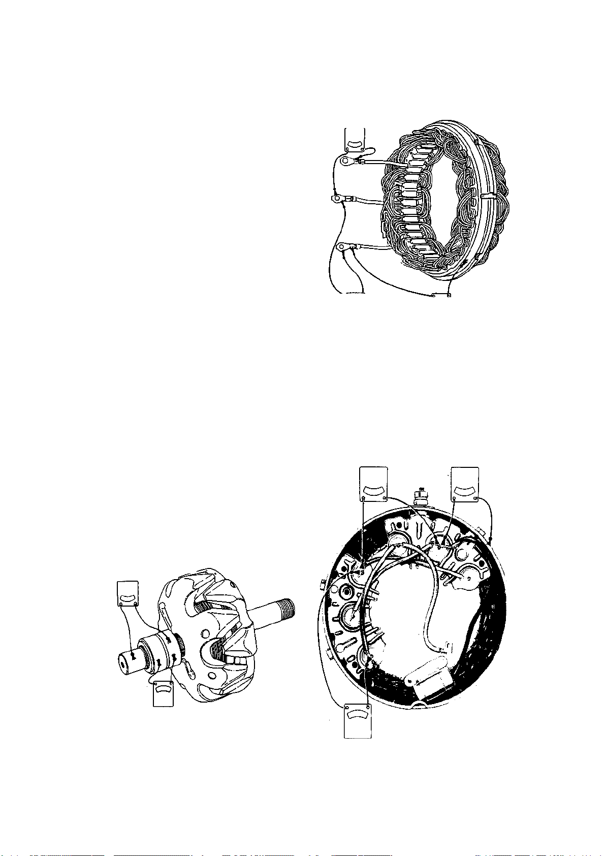
ENGINE AND ENGINE REBUILDING 77
CHECK FOR OPENS
GROUNDS)
OHMMETER
3. Inspect rotor slip rings for scoring. They
may be cleaned with 400 grit sandpaper (not
emery), rotating the rotor to make the rings
concentric. Maximum out-of-true is 0.001 in.
If slip rings are deeply scored, the entire ro
tor must be replaced as a unit.
4. Inspect brushes for wear; minimum
length is ¥4 in.
ALTERNATOR COMPONENT TESTING
Rotor *
Attach one lead of a 110 volt test lamp or an
ohmmeter to either slip ring, and the other
lead to the rotor shaft or poles. A lighted test
lamp or low ohmmeter reading indicates
grounded field windings.
Attach the lamp or ohmmeter connections
to each slip ring. The windings are open if
the lamp fails to light or the ohmmeter reading is high.
Connect a 12 volt battery and an ammeter
in series with the slip rings to check for shorts.
The windings are shorted if the reading exceeds 1.5 amps. An ohmmeter may be substituted for the same check and will show a
resistance reading of less than 6 ohms if the
windings are shorted.
(CHECK FOR OPENS)
TESTING STATOR
OHMMETER
OHMMETER
(CHECK FOR
OPENS)
Stator testing—except "perforated
case" models
OHMMETER
(CHECK FOR
Stator
Attach the test lamp or ohmmeter to the stator frame and one of the stator leads. A lighted
lamp or low resistance reading indicates
grounded windings.
Successively connect the test equipment
between each pair of stator leads. Open
windings will produce a high resistance and
prevent the test lamp from lighting.
Shorts require special test equipment. If
(CHECK FOR TESTING ROTOR
OHMMETER
Rotor testing
GROUNDSKOHMMETER).
Page 83

OHMMETER
OHMMETER
Stator testing—"perforated case" models
Page 84
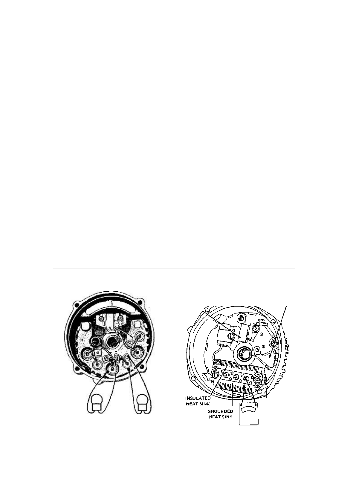
78 ENGINE AND ENGINE REBUILDING
WASHER
all other tests fail to locate the problem, it is
more than likely a short in the stator.
Separately Mounted Diodes (Pressed-in
Type)
The diodes may be checked for shorts or
opens by using an ohmmeter or a 12 volt test
lamp.
CAUTION: Under no circumstances use a
110 volt test lamp.
Use a V/z volt cell ohmmeter that has been
adjusted to the lowest range scale. Attach one
lead to me heat sink and the other to the diode
lead. A good diode will show a high and a low
reading depending on the connection switch.
Two low or two high readings signal a faulty
diode. Check the other diodes in the same
manner. When servicing "perforated case"
models, repeat this for the diodes in BOTH
heat sinks.
Check the end-frame mounted diodes by
connecting one test lead to the frame and the
other to the diode lead. Reverse the connection and check the readings. The same diagnosis is true here as for the heat sink diodes.
If an ohmmeter is not available, substitute
a 12 volt test lamp. Connect and switch connections in the same fashion as with the
ohmmeter. The lamp will light in only one
direction. If it lights or fails to light in both
directions, the diode is bad.
Diode Rectifier Bridge
Refer to the accompanying illustration for
component identification. Use a self-powered ohmmeter set on its lowest reading scale.
CAUTION: DO NOT use a 110 volt test
lamp to test the rectifier bridge—use only
a self-powered ohmmeter.
Connect one ohmmeter lead to the
grounded heat sink. Connect the other lead
to each of the three rectifier bridge terminals
(one at a time) and note the ohmmeter readings (1st set). The readings at each of the
bridge terminals should be virtually identical. Reverse the ohmmeter leads and repeat
the test, again noting the meter readings (2nd
set).
Connect one ohmmeter lead to the insulated heat sink. Connect the other lead to each
of the three rectifier bridge terminals (one at
a time) and note the ohmmeter readings (3rd
set). Reverse the ohmmeter leads and repeat
the test, again noting the meter readings (4th
set).
Readings taken for any one full set should
be virtually identical, conversely, if you get
two different readings WITHIN the same set,
replace the rectifier bridge assembly. When
comparing readings between sets 1 and 2, one
set should read high, the other low. When
comparing readings between sets 3 and 4,
again, one set should be high, the other low.
TESTING RECTIFIER BRIDGE
BRUSH ^-<^=5r==^>^ REGULATOR
HOLDER
Diode check Rectifier bridge check
TEST LAMP
TEST IAMP
INSULATING
OHMMETER
Page 85
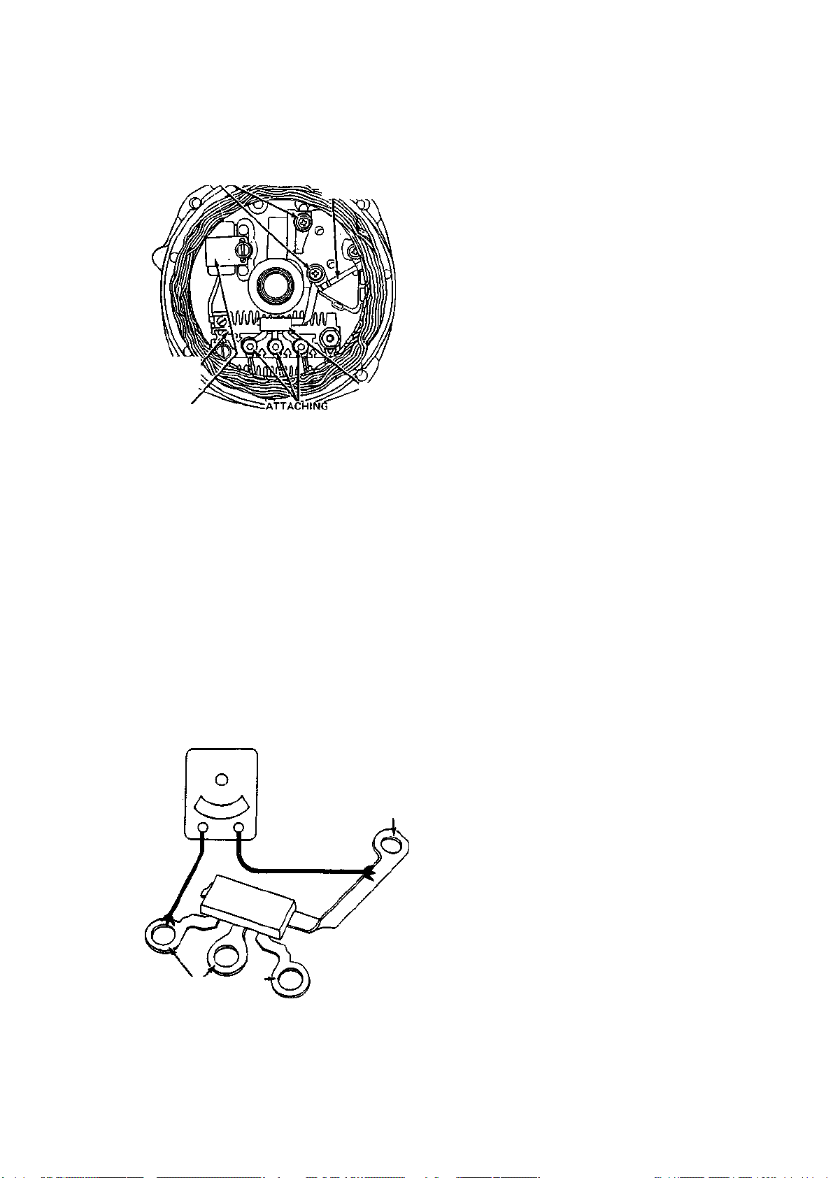
ENGINE AND ENGINE REBUILDING 79
BRIDGE
E
Diode trio
check
END FRAME VIEW
INSULATING _
WASHERS ^ij^^^^^^^^s: (USED ON
RECTIFIER
CAPACITOR
Location of diode trio
Diode Trio
i ______
NUTS
RESISTOR
SOME MODE LSI
DIOD
CAUTION: DO NOT use a 110 volt test
lamp to test the diode trio—use only a selfpowered ohmmeter. Set the ohmmeter lead
to the single terminal of the diode trio.
Connect the other lead to each terminal (one
at a time) of the three terminal grouping,
and note the ohmmeter reading at each terminal (1st set). Reverse the ohmmeter leads
and repeat the same test, again noting the
ohmmeter readings (2nd set). Ohmmeter
readings WITHIN one set should be virtually identical. When comparing readings
BETWEEN each set, one set should be
high, the other low.
TESTING TRIO
OHMMETER
SINGLE CONNECTOR
REPAIRS
Pressed-in Diode Replacement
Despite rumors to the contrary, diodes of this
type may be replaced. It is not necessary to
replace me entire generator assembly as some
unscrupulous garage owners convinced their
unwary customers in the introductory days of
the AC generator.
Two types of diodes, positive and negative,
are used in the AC generator. The heat sink
contains the positive diodes and these are
marked with red. End frame diodes are the
negative ones and they have black markings.
Do not attempt to drive a diode from its bore
or the other diodes may be damaged.
Support the end frame in an arbor press-,
select a suitable removal spacer, and press the
diode from the frame. Use the same method
to install a replacement diode.
To replace heat sink diodes (which includes all of the diodes of "perforated case"
models), it is necessary to separate the heat
sink from the frame. Observe the stack-up
closely to ensure correct reassembly of the
BAT and GRD terminal bolts. Replace the
diodes as described above, reassemble the
bolt stack-ups and attach the heat sink to the
end frame.
Bearing Replacement
The drive end frame bearing is removed by
detaching the retainer frame from the end
plate and pressing the bearing out. Fill the
bearing Yi full with multipurpose grease; do
not overfill. Press the bearing into the end
frame. Install the retainer pkte.
The slip ring end frame bearing of the 6 in.
"perforated-case" generator is pressed off the
rotor shaft. The replacement is pressed over
the rotor shaft by using an arbor press.
The 5.5 in. aluminum Delcotron slip-ring
end bearing is replaced by pressing it out towards the inside of the case. To install the
replacement, position a flat plate over the
bearing and press it into the outside of the
case. Press all bearings and diodes flush with
their receptacles.
THREE CONNECTORS
Brush and Holder Replacement
NOTE: It is always easier and worth the
minimal extra cost to replace the brushes
with their holder. For some models, brushes
themselves are not serviced separately. For
externally regulated models, except the
"perforated case" Delcotron:
Page 86
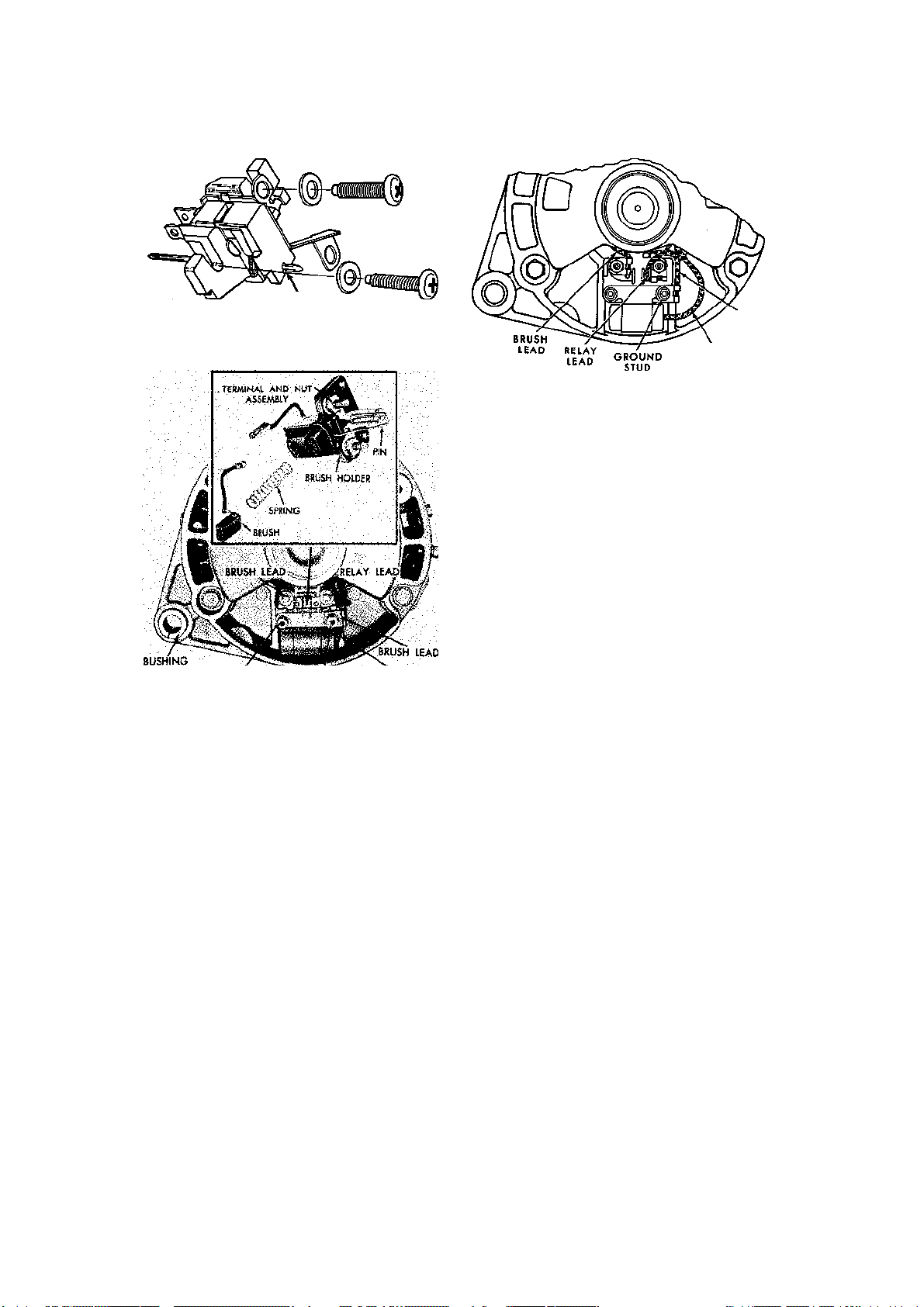
80 ENGINE AND ENGINE REBUILDING
BRUS
H
Brush holder
—
Externally regulated Delcotron, ex
-
CONDENSER
LEAD
PIN
cept "perforated case" models
Brush holder wiring—"perforated case" Delcotron
placement of the internal voltage regulator.
1. Remove two brush holder screws and
stator lead to strap nut and washer, brush
holder screws and one of the diode trio lead
strap attaching screws.
NOTE: The insulating washers must be re-
placed in the same position on reassembly.
2. Remove brush holder and brushes. The
voltage regulator may also be removed at this
time, if desired.
3. Brushes and brush springs must be free
of corrosion and must be undamaged and
completely free of oil or grease.
BSUSH HOIDER GROUND CONDENSER
MOUNTING SCREW STUD LEAD
Brush holder—"perforated case" Delcotron
1. Remove the stator lead nut that also
holds the relay terminal connector.
2. Remove the two mounting screws and
the brush holder assembly.
3. When installing the new brush holder
assembly, depress the brushes and insert a
straightened paper clip through the holes
provided in the holder for brush retention.
4. Install the brush holder assembly.
5. Remove the paper clip after the alter
nator is assembled.
For externally regukted models of the
"perforated case type:
If the alternator was disassembled according to the previous procedure, just install the
new brush holder during assembly. If the alternator has not yet been disassembled, refer
to steps 1—4 and 12e of the previous Disassembly and Assembly procedure to replace
the brush holder. For internally regulated
Delcotrons:
NOTE: This procedure also includes re-
4. Insert spring and brushes into holder,
noting whether they slide freely without
binding. Insert wooden or plastic toothpick
into bottom hole in holder to retain brushes.
NOTE: The brush holder is serviced as a
unit; individual parts are not available.
5. Reassemble in reverse order of disas
sembly.
Voltage Regulator
Three types of voltage regulators have been
used in the Corvette since 1963. The first type
of regulator, hereafter referred to as Type
One, is a double-contact model which is
mounted externally, separately from the alternator. The Type One regulator was used
on most 1963-68 and some 1969 Corvettes.
This regulator is housed in a basically square,
black metal case and has four electrical terminals.
The second type of regulator, hereafter
called Type Two, is a transistorized model
which was offered as an option with the transistorized ignition system in 1965. The Type
Two regulator is externally mounted and uses:
a) one transistor which assists in limiting the
voltage to a preset value, and b) two diodes
Page 87
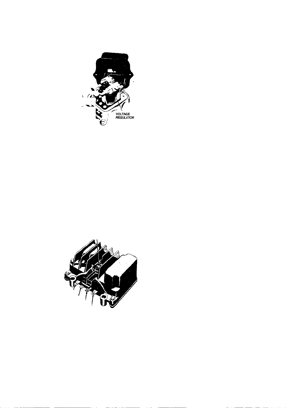
ENGINE AND ENGINE REBUILDING 81
FIELD RELAY
TERMINAL
ACCESS PLUG TO
VOLTAGE ADJUSTMENT
"LATCH"
"F" TERMINAL
NO. 2 TERMINAL NO. 3
TERMINAL NO. 4
Type One voltage regulator
"F" TERMINAL NO. 2
TERMINAL NO. 3
TERMINAL NO. 4
TERMINAL
Type Two voltage regulator
which protect the system from transient voltage which may occur. The Type Two regulator is easily identified by the finned regulator
casing.
The third type of regulator, hereafter called
Type Three, is mounted inside of the Delcotron alternator. This electronic regulator, used
in some 1969 and all later Corvettes, is nonadjustable and must be replaced if defective.
f
properly grounded and do not overtighten the
mounting screws, as this will cancel the cushioning effect of the rubber grommets.
Type Three
1. Remove the alternator from the vehicle
as previously outlined.
2. Scribe a line on the alternator case from
front-to-rear which will aid in attaining the
proper relationships between components
during assembly.
3. Remove the four through-bolts which
join the end frame assemblies.
4. Separate the end frames by carefully
prying between the drive (front) end frame
and the stator. DO NOT pry between the slip
ring (rear) end frame and the stator. The sta
tor is wired to the rectifier bridge which is
attached within the rear end frame.
5. Disconnect the three stator wire termi
nals at the rectifier bridge connections.
6. Remove the stator from the slip ring end
frame. It may be necessary to carefully pry
the stator from the frame.
7. Remove the three screws which retain
the brush holder and regulator. Note the po
sitions of the two screws which are equipped
with plastic insulating washers—these screws
MUST be installed in their original locations.
NOTE: Some alternators also have a resis-
tor which is installed between the regulator
and brush ground terminals. Note its position and reinstall it in the same manner.
8. Lift the brush holder and regulator out
of the alternator frame.
9. The regulator is installed in the reverse
of the previous steps. Before installing the
brush holder, push the brushes into the
holder and insert a straightened paper clip
through the holes provided in the holder for
brush retention. Remove the paper clip after
the alternator is assembled.
REMOVAL
AND
INSTALLATION Types One and
Two
1. Disconnect the negative battery cable
at the battery.
2. Disconnect the wiring harness from the
regulator.
3. Remove the regulator mounting screws
and remove the regulator.
4. Installation is the reverse of the pre
vious steps. Be sure that the regulator base is
VOLTAGE ADJUSTMENT
Types One and Two Only
The adjustment procedure is the same for
both types of regulators, except for the loca tions where the adjustment is made. On the
Type One regulator, the adjustment screw is
under the regulator cover; the Type Two regulator is adjusted externally after removing
the alien screw from the adjustment screw
access hole.
1. Insert a % ohm-25 watt fixed resistor
into the charging circuit at the horn relay
Page 88
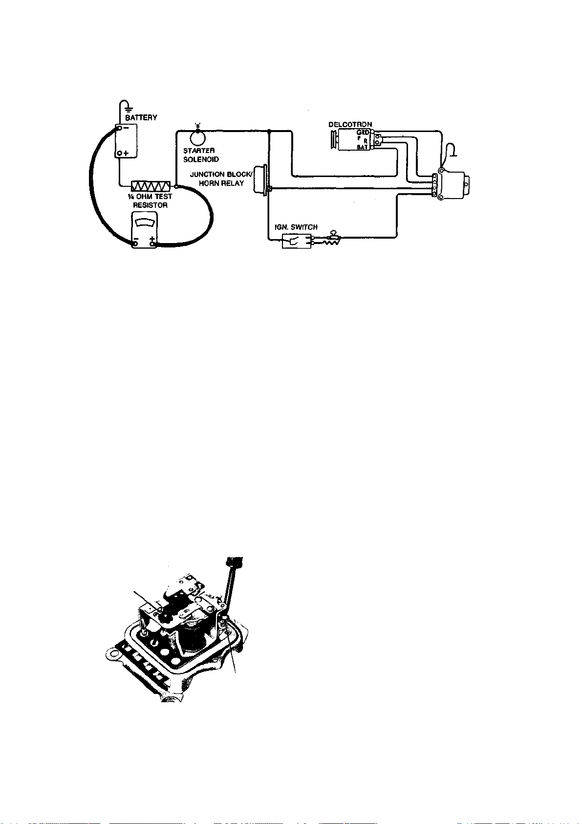
82 ENGINE AND ENGINE REBUILDING
REGULATOR
AIR GAP
ONLY
ADJUSTING SCREW
VOLTMETER
Schematic for testing the regulator voltage setting
junction block, as shown in the accompanying illustration.
2. Install a voltmeter as shown in the ac
companying illustration.
3. Warm the engine by running it for
about fifteen minutes at 1500 rpm or more.
4. Disconnect the regulator connector and
reconnect it to cycle the regulator.
5. Read the voltage on the voltmeter. If
the voltage reading is 13.5-15.2 volts, the
regulator does not need adjustment or re
placement. If the voltage is not within these
limits, leave the engine running at 1500 rpm
and proceed to step 6.
6. On Type One regulators, disconnect
the regulator connector and remove the reg
ulator cover. Reconnect the regulator con
nector. On Type Two regulators, remove the
adjustment screw access plug from the regu
lator case (the plug is actually an alien screw).
7. Observe the voltmeter reading and
turn the voltage adjustment screw until the
voltmeter reads 14.2-14.6 volts.
8. On Type One regulators, disconnect
ADJUSTING NUT
(TURN TO ADJUST
VOLTAGE SETTING)
Type One voltage regulator—voltage adjustment
the regulator connector, install the cover and
reconnect the regulator connector.
9. Continue running the engine at 1500
rpm to re-establish the internal temperature
of the regulator (Type One only).
10. Again, cycle the regulator by discon
necting and reconnecting the regulator con
nector.
11. Recheck the voltmeter reading: If it is
between 13.5 and 15.2 volts, the regulator is
good; is not, replace the regulator.
CAUTION: On Type One regulators, al-
ways disconnect the regulator connector
before removing the regulator cover, to
prevent short circuits.
12. On Type Two regulators, If the volt
meter reading is okay, reinstall the access hole
plug.
VOLTAGE TESTING
Type Three Regulator Only
Though other tests of the internal voltage
regulator exist, the following test is quite accurate and requires a minimum of tools.
NOTE: The following test must be per-
formed with the engine at normal operating
temperature.
1. Attach one lead of a voltmeter to the
"BAT" terminal of the alternator and the other
lead to a good ground.
2. Start the engine and operate at about
1500 rpm.
3. Observe the voltmeter reading: If it is
approximately 13.5-15.2 volts, the regulator
is properly limiting the voltage to the bat
tery. If the voltage is above about 15.2 volts,
replace the voltage regulator as previously
described. If the voltage is below 13 volts,
locate the test hole in the rear end frame of
Page 89
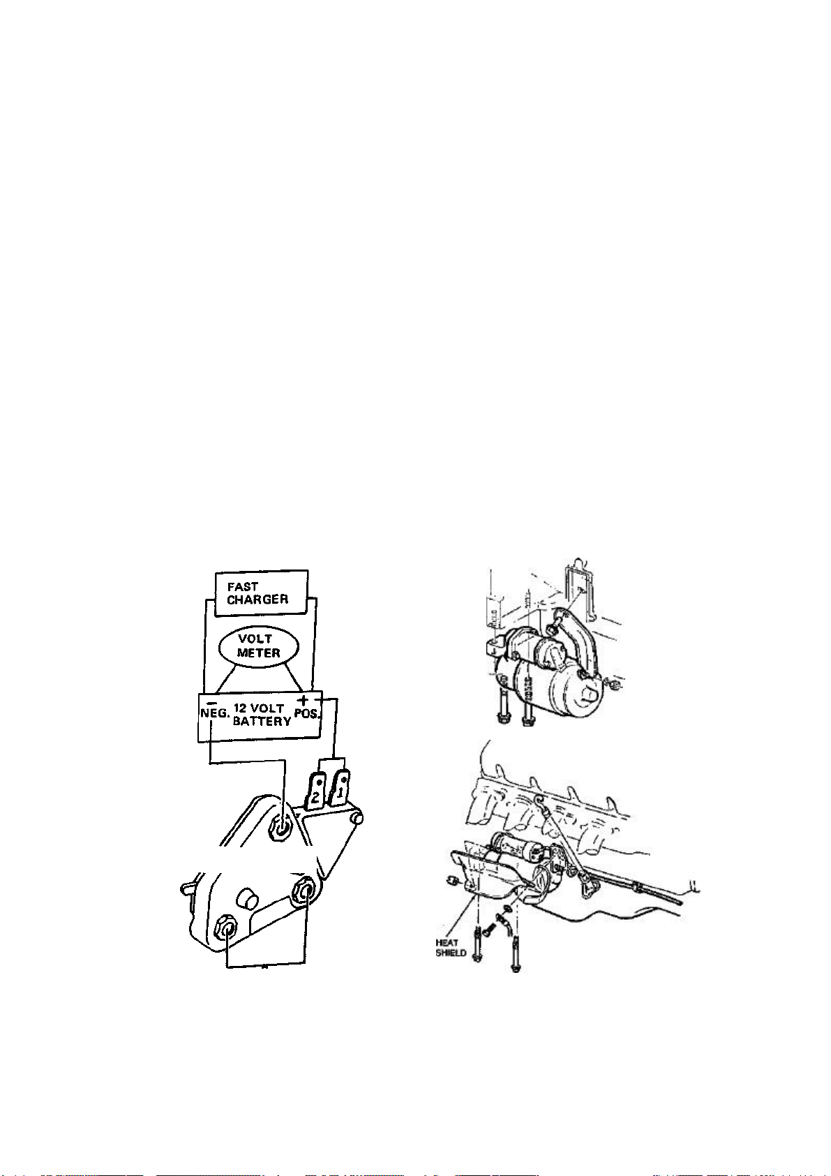
ENGINE AND ENGINE REBUILDING 83
.
REGULATOR
Starter mounting
—
small block (top) and big block
(bottom)
the alternator (refer to the illustration under
Alternator Tests.) Insert a screwdriver into the
test hole about %" to depress the field
grounding tab. Under no circumstances
should you push the screwdriver further than
1" into the alternator. If the voltage reading
increases as the screwdriver is put into the
test hole, the alternator is functioning properly and the regulator must be replaced. If
the voltage reading did not increase with the
insertion of the screwdriver, the alternator
must be disassembled and tested.
NOTE: If the test hole is not accessible, re-
move the alternator and test the following
components: rotor, stator, rectifier bridge,
diode trio, and brushes (%," minimum
length). Replace any component which may
be defective. If these components are okay,
replace the voltage regulator.
TESTING TYPE THREE REGULATOR
OFF THE CAR
NOTE: This test requires the use of a fast
charger.
1. Remove the voltage regulator from the
alternator.
2. Connect voltmeter and fast charger to
battery as shown.
3. Connect regulator and test light as
shown, observing battery polarity.
4. The test light should be on when con
nected.
5. Turn on the fast charger and slowly in
crease the charge rate. Check the voltmeter
and make sure that the test light goes out at
a minimum of 13.5 volts, and a maximum of
16.0 volts.
Starter
REMOVAL AND INSTALLATION
1. Disconnect the battery cables at the
battery.
2. Raise the front of the vehicle to a con
venient working height and support with
jackstands.
3. Disconnect the wiring from the starter
solenoid. Replace each connector nut as the
terminals are removed as the thread sizes dif
fer between connectors. Note or tag the wir
ing positions to avoid improper connections
during installation.
4. Remove the front starter support bracket
and the heat shield (if so equipped).
voltage regulator on the bench
TRANSISTORIZED
TEST LIGHT Testing
Page 90

Year
1963-64
1965-67
1968
1969
1970
1971-72
1100628
1100693
1100696
1100693
1100794
1100696
1100696
1100900
.1100901
1100544
1100543,1100950
1100566
Model
00
m
z
Q
m >
D
m
z o
m
3D m co
c
Alternator and Regulator Specifications
Regulator
Volts to
Close
Regulator
Air
Gap
(in.)
0.067 0.014 13.8-14.8
0.067 0.014 13.8-14.8
0.067 0.014 13.8-14.8
Point
Gap
(in.)
Volts at
125°
Alternator
Output @
Field Current
Draw
@12V
1 .9-2.3
2.2-2.6
2.2-2.6
2.2-2.6
2.2-2.6
2.2-2.6
2.2-2.6
2.2-2.6
2.2-2.6
4-4.5
4-4.5
2.2-2.6
Generator RPM
2000
27A 37A
27A 37A
29A 42A
27A 37A
27A 37A
29A 42A
27A 37A
27A 37A
27A 37A
® ®
® 37A
25A 35A
5000
Model
1119512 0.015 0.030 2.3-3.7 0.067 0.014 13.5-14.4
1119515 0.015 0.030 2.3-3.7 0.067 0.014 13.5-14.4
1119515 0.015 0.030 2.3-3.7 0.067 0.014 13.5-14.4
1119515 0.015 0.030 2.3-3.7 0.067 0.014 13.5-14.4
1119515 0.015 0.030 2.3-3.7 0.067 0.014 13.5-14.4
1119515 0.015 0.030 2.3-3.7 0.067 0.014 13.5-14.4
1119515 0.015 0.030 2.3-3.7 0.067 0.014 13.5-14.4
1119515 0.015 0.030 2.3-3.7 0.067 0.014 13.5-14.4
1119515 .0.015
1119515 0.015 0.030 1.5-3.2
1119515 0.015 0.030 1.5-3.2
1119515 0.015 0.030 1.5-3.2
Field Relay
Air
Gap
(in.)
Point
Gap
(in.)
0.030 2.3-3.7 0.067 0.014 13.5-14.4
Page 91
oo 0
D
0 0
D
0
0
D
D
co 0 0
3
00 CO 0 B
co
0
c
i
c
o
c
co
0
c
T—
o
8 i
d
i i ! i
ji li 1 1
( Ij s
'S
1
! i i ! E E 1
E E
2 "i !
5
<
(
i
5
(
i
1
S S
J
"i
J
i
S
S S
J
j
s
j
.
j: .c
f: s:
-
s
^ .c
•
'g '! 'I
d
d
i
1
2
i
i
1
i
5
d
c c
i
]
1
1
d
d
O
d d o
in
1
c>
en o
Q)
•5.
<
C
.,
4
@
® ®
J
3
^
c
O i
^ CO
4
C
^
^ en
1
1
ll
CO
<N
c
! ci
i
i
1iin in
I
>
m in
i
3
p
a
o
•*
1 I 1
CM
i
E
|
o
c
d output
ch j used
for r
s
1
"
^
£
1
CO
CO & ? 3
S
s
0 3 S
s
T" 8 8 0
g g
8
g
s
S
O
C
g o
ll
S
s
"o
f&*
K
.
a
S
ENGINE AND ENGINE REBUILDING 85
00
oo
CO
00
CO
CO
T—
o
o
d d
fe
o
d d
CM
CM
^ *?
in in
o
§
d
in
in en
^ j; iE
<
<
<
1
00
c\i
c\i
i— o
CO
a
0
0
a
a
i
0
C
]
0 0
1
i
;
3
>
•
)
1
j
i
}
>
5
1
)
(
\
y-«
C
4
<
J
?
c
\
3
1
c
>
1
)
a
>
1
c
\
0
a
a
i
;
i
]
i
r
4
)
1
1*
;
IO
O)
0
a
0
0
0
1
J
< 1
I
•
i
5
1
)
1
4
4
>
1
•
CO
0
CO
1!
•
'g
Integrate
<
CO
o
00 00
a S <a
O)
S
0
00 CO
00 00
CO CO
>
a
CO
1
•
\
\
\
c
I
i
£
i
I 1
Integrate
i
Integrate
o
3
E
.c
3
)
<
i
)
c
.c
0
If
-;
T
-
C
T
^ E
. .E
r-
c
c
8
CM O
T
CO
?
8
0
o
C
T
J
1
^
2
'
^
m
1
•s a
CO **~
in
o
C .«
k_ S
00
0®
22
'Q_
||
Page 92
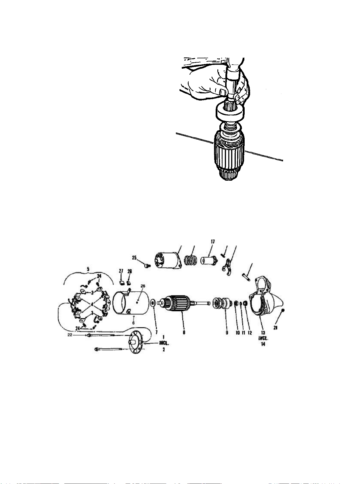
86 ENGINE AND ENGINE REBUILDING
20
23
5. Loosen the two main starter mounting
bolts, support the starter and remove the
bolts. Lower the starter front end first and
remove the starter.
6. Reverse the previous steps to install the
starter. Torque the two main starter mount
ing bolts to 25-35 ft. Ibs.
STARTER OVERHAUL
Drive Replacement
1. Disconnect the field coil straps from
the solenoid.
2. Remove the two starter through bolts.
Separate the commutator end frame, field
frame, drive housing, and armature from each
other.
3. Slide the two-piece thrust collar off of
the end of the armature shaft.
4. Slide a %" deep socket or a piece of
pipe of suitable size over the drive end of the
armature shaft and against the snap-ring re
tainer. Carefully tap the socket or pipe to
wards the armature to drive the retainer off
of the snap-ring.
5. Remove the snap-ring from the arma
ture shaft. Be careful, as the snap ring will
Use a piece of pipe to drive the retainer toward
the snap-ring
distort rather easily. If the snap ring is distorted after removal, it must be replaced.
6. Slide the starter drive and retainer
from the armature shaft.
1. Commutator end frame
2. Bushing (not pictured)
3. Brush
4. Brush holder
5. Brush and holder package
6. Field and frame assembly
7. Washer
8. Armature
9. Drive assembly
10. Retainer
15 16
11. Snap-ring
12. Thrust washer
13. Drive end housing
14. Bushing (not pictured)
15. Solenoid assembly
16. Plunger spring
17. Plunger.
18. Lever
19. Roll pin
20. Lever pivot bolt
Exploded view of the starter
19 18
21. Lever bolt nut
22. Through bolt
23. Through bolt
24. Brush screw
25. Bolt
26. Field retaining screw
27. Plug
28. Grommet
Page 93
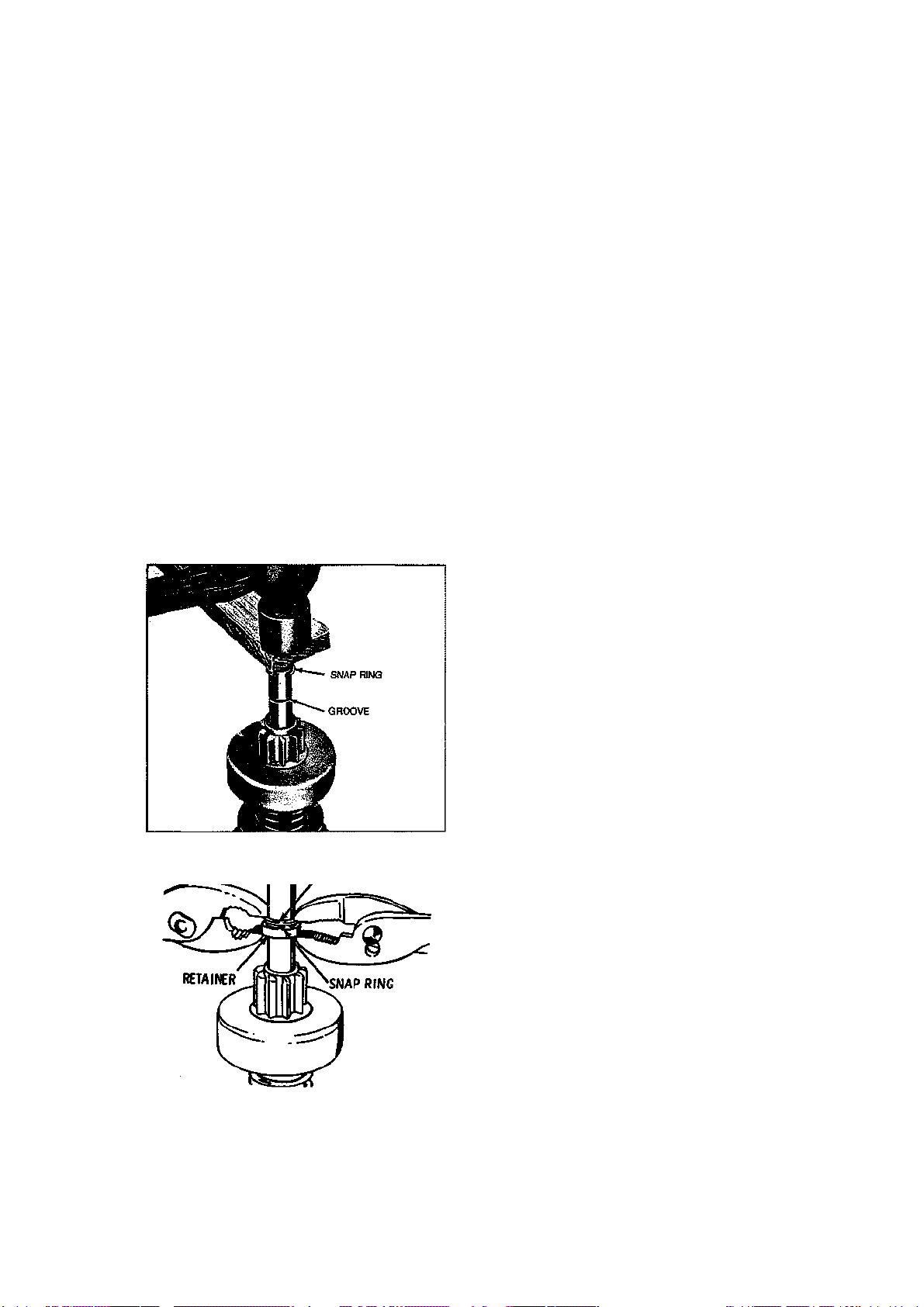
ENGINE AND ENGINE REBUILDING 87
7. To reassemble, lubricate the drive end
of the armature shaft with silicone lubricant
and slide the starter drive onto the shaft with
the pinion gear facing away from the arma
ture. Slide the retainer onto the shaft with
the cupped portion facing away from the ar
mature.
8. Support the armature assembly in a
vertical fashion with the drive end pointing
upward. Position the snap ring on the top of
the shaft, and carefully place a block of wood
on the snap ring. Keep the snap ring cen
tered. Tap the block of wood to drive the snap
ring onto the shaft. Using a deep socket that
will fit around the shaft without interference
and yet contact the snap ring, force the snap
ring downward into its groove on the shaft.
9. Place the thrust washer on the shaft.
Using two pairs of pliers as shown in the ac
companying illustration, force the snap-ring
retainer over the snap ring and engage it with
the thrust washer.
10. Lubricate the drive housing bushing
with silicone lubricant. Install the armature
and clutch assembly into the drive housing,
engaging the solenoid shift lever with the
clutch, and positioning the front end of the
armature shaft into the drive housing bushing.
11. Apply a sealing compound (G.M.
#1050026 or its equivalent) to the drive
housing around the area where the field frame
mates with the housing.
12. Slide the field frame assembly over the
armature and guide the brushes over the ar
mature commutator. Continue to push the
field frame until the frame mates to the drive
housing. Work slowly and carefully to pre
vent brush damage.
13. Lubricate the bushing in the commu
tator end frame with silicone lubricant, being
careful not to get the lubricant on surround
ing components.
14. Place the leather washer onto the ar
mature shaft and slide the commutator end
frame over the shaft and into position against
the field frame. Line up the bolt holes, then
install and tighten the two starter through
bolts.
NOTE: If replacement of the starter drive
fails to cure improper engagement of the
starter pinion to the flywheel, there are
probably defective parts in the solenoid
and/or shift lever. In this case, it would
probably be best to take the starter assembly (incl, solenoid) where a pinion clearance check can be made. If the pinion
clearance is incorrect, disassemble the solenoid and shift lever. Inspect these parts
and replace as necessary.
Forcing snap-ring over the armature shaft
Snap-ring installation
(353 THRUST WAS WR
Brush Replacement
1. Disassemble the starter by following
Steps 1 and 2 of the previous Drive Replace
ment procedure.
2. Replace the brushes one at a time to
avoid having to mark the wiring. For each
brush: Remove the brush retaining screw and
remove the old brush. Install the new brush
in the same direction (krge end towards the
end of the field frame). Position the wire con
nector on the top of the brush, line up the
holes and reinstall the screw. Make sure the
screw is snug enough to ensure good contact.
3. Reassemble the starter according to
Steps 10—14 of the previous procedure.
Solenoid Replacement
1. Remove the screw and washer from the
motor connector strap terminal.
Page 94

Year
1963- 64
1963
1964
1965
1966
1967- 68
1969
Engine
Displacement (CM
in.)
327
327
327
327
327
327
327
327
327
327
327
396
327
327
427
427
327
327
427
427
427
427®
350
350
Fuel
Delivery
System
4bbl
4bbl
4bbl
Fuel Inj
4bbl
Fuel Inj
4bbl
4bbl
4bbl
4bbl
Fuel Inj
4bbl
4bbl
4bbl
4bbl
4bbl
4 bbl
4bbl
4bbl
3-2 bbl
3-2 bbl
4 bbl
4 bbl
4 bbl
General Engine Specifications
Horsepower
(ffirpmn
250 @ 4400 350 @ 2800 4.00 x 3.25 10.5:1
300 @ 5000 360 @ 2800 4.00 x 3.25 10.5:1
340 @ 6000 344 @ 4000 4.00 X 3.25 11.25:1
360 @ 6000 352 @ 5000 4.00 x 3.25 11.0:1
365 @ 6200 360 @ 3600 4.00 x 3.25 11.0:1
375 @ 6200 350 @ 4000 4.00 x 3.25 11.0:1
250 @ 4400 350 @ 2800 4.00 x 3.25 10.5:1
300 @ 5000 360 @ 3200 4.00 x 3.25 10.5:1
350 @ 5800 360 @ 3800 4.00 x 3.25 11.0:1
375 @ 6200 350 @ 4000 4.00 x 3.25 11.0:1
365 @ 6200 350 @ 4600 4.00 x 3.25 11.0:1
425 @ 6400 41 5 @ 4000 4.094 x 3.76 11.0:1
300 @ 5000 360 @ 3200 4.00 x 3.25 10.5:1
350 @ 5800 360 @ 3600 4.00 x 3.25 11.0:1
390 @ 5200 460 @ 3600 4.25 x 3.76 10.25:1
425 @ 5600 460 @ 4000 4.25 x 3.76 11.0:1
300 @ 5000 360 @ 3400 4.00 x 3.25 10.0:1
350 @ 5800 360 @ 3600 4.00 x 3.25 11.0:1
390 @ 5400 460 @ 3600 4.25 x 3.76 10.25:1
400 @ 5400 460 @ 3600 4.25 x 3.76 10.25:1
435 @ 5800 460 @ 4000 4.25 X 3.76 11.0:1
430 @ 5200 450 @ 4400 4.25 x 3.76 12.0:1
300 @ 4800 380 @ 3200 4.00 x 3.48 10.25:1
350 @ 5600 380 @ 3200 4.00 x 3.48 11.0:1
Torque @ rpm
(ft. lbs.)«
Bore and
Stroke (in.)
Compres-
sion Ratio
OH
Pressure
@2000
rpm
45
45
45
45
45
45
45
45
45
45
45
45
45
45
60
60
45
45
65
65
65
65
45
45
09
OB
m
z o
m
> z
o
m
z o
m
33
m
CD
c
o
Page 95

o
CO X
in
CM
ENGINE AND ENGINE REBUILDING 89
9
in
CM
ci
CO X
8
CO X
o o
in in in in
?
•*
CO X
o p •<*
X
in CM
•^
CO X
o p
CO X
in
CO X
o o
o
8
CO
•* X
CO X
o o
p
8
8
s
o
§
CM
in
CD
co
8
©
in in cj
in in
CM
8
(O
co
©
8
o o
o
•sf
in 5
8
©
I
&
I
g
CO
§
R!
en
§
Page 96

o m O
z
m
m 0 Z m 33
c
General Engine Specifications (cont.) g
(O
m
oo
Engine
Displace-
Year
1979
1980
1981
350
1982
350
1984
350
•Beginning 1972, horsepower and torque are SAE net figures. They are measured at the rear of the transmission with all accessories installed and operating.
Since the figures vary when a given engine is installed in different models, some are representative rather than exact. ® Limited production engine L88, for
special purposes © Not available in California <D Throttle body fuel injection
ment (cu
In.)
350
350
305
350
350
Fuel
Delivery
System
4bbl
4bbl
4bbl
4bbl
4bbl
4bbl
TBI®
TBI®
Horsepower
@rpmB
195 @ 4000
225 @ 5200
180 @ 4200
190 @ 4400
230 @ 5200
1 90 @ 4200
200 @ 4200
205 @ 4300
Torque @ rpm
(fl. lbs.)e
285 @ 3200
270 @ 3600
255 @ 2000
280 @ 2400
275 @ 3600
280 @ 1600
285 @ 2800
290 @ 2800
Bore and
Stroke (in.)
4.000 x 3.480
4.000 x 3.480
3.736 x 3.480
4.000 x 3.480
4.000 x 3.480
4.000 x 3.480
4.000 x 3.480
4.000 x 3.480
Compression Ratio
8.2:1
45
8.9:1
45
8.5:1
45
8.5:1
45
9.0:1
45
8.2:1
45
9.0:1
45
9.0:1
45
Oil
Pressure
@2000
rpm
Page 97

Valve Specifications
Year
1963-64
1965-66
1967
1968
1969
1970
Engine
Displacement (cu
In.)
327 46 45
327 (High Pert)
327
327 (350 hp)
327 (fuel inj)
396 46 45
427 46 45
427 (425 hp)
327 (300 hp)
327 (350 hp)
427 (390, 400 hp)
427 (435 hp)
327 (exc 350 hp)
327 (350 hp)
427 (exc 435 hp)
427 (435 hp)
350 46 45
350 (350 hp)
427 (390, 400 hp)
427 (435 hp)
350 46 45
454 46 45
454®
46
r
46
46
46
46
46
46
46
46
46
46
46
Seal
Angle
(deg)
46 45
46
46
46
46
Face
Angle
(deg)
45
45
45
45
45
45
45 NA NA
45
45
45
45
45
45
45
45
45
Spring Test
Pressure (Ibs.
175 @ 1.26
175 @ 1.26
175 @ 1.26
175 @ 1.26
175 @ 1.26
315 @ 1.38
315 @ 1.38
315 @ 1.38
200 @ 1.25
200 @ 1.25
315 @ 1.38
198 @ 1.25
198 @ 1.25
315 @ 1.38
315 @ 1.38
200 @ 1.25
200 @ 1.25
312 @ 1.38
312 @ 1.38
80 @ 1.70
75 @ 1.88®
75 @ 1.88®
@ in.)
1%
1.70
1.70
1.88
1.88
1.70
1.70
1.88
1.88
Spring
Installed
Height (in.)
1.66
1.66
1.66
1.66
1.66
1.88
1.88
1%2
1=/32
17/8
1^32
1%
1%
Stem to Guide
Clearance (in.)
Intake
0.0010-0.0027
0.0010-0.0027
0.0010-0.0027
0.0010-0.0027
0.0010-0.0027
0.0005-0.0024
0.0010-0.0027
0.0010-0.0027
0.0010-0.0027
0.0010-0.0027
0.0010-0.0027
0.0010-0.0027
0.0010-0.0027
0.0010-0.0027
0.0010-0.0027
0.0010-0.0027
0.0010-0.0027
0.0010-0.0027
0.0010-0.0027
0.0010-0.0027
0.0010-0.0037
0.0010-0.0037
0.0010-0.0037
0.0016-0.0033
0.0016-0.0033
0.0016-0.0033
0.0016-0.0033
0.0016-0.0033
0.0012-0.0029
0.0015-0.0032
0.0015-0.0032
0.0015-0.0032
0.0015-0.0032
0.0015-0.0032
0.0015-0.0032
0.0017-0.0027
0.0017-0.0027
0.0015-0.0032
0.0015-0.0032
0.0010-0.0027
0.0010-0.0027
0.0010-0.0027
0.0010-0.0027
0.0010-0.0047
0.0010-0.0047
0.0010-0.0047
Exft3EISt
0.3404-0.3417
0.3404-0.3417
0.3404-0.3417
0.3410-0.3417
0.3410-0.3417
0.3715-0.3722
0.3715-0.3722
0.3715-0.3722
0.3410-0.3417
0.3410-0.3417
0.3715-0.3722
0.3715-0.3722
0.3410-0.3417
0.3410-0.3417
0.3715-0.3722
0.3715-0.3722
0.3410-0.3417
0.3410-0.3417
0.3715-0.3722
0.3715-0.3722
0.3414
0.3718
0.3718
Stem Diameter
(In.)
Intake
0.3410-0.3417
0.3410-0.3417
0.3410-0.3417
0.3410-0.3417
0.3410-0.3417
0.3713-0.3720
0.3713-0.3720
0.3713-0.3720
0.3410-0.3417
0.3410-0.3417
0.3713-0.3720
0.3713-0.3720
0.3410-0.3417
0.3410-0.3417
0.3713-0.3722
0.3713-0.3722
0.3410-0.3417
0.3410-0.3417
0.3713-0.3722
0.3713-0.3722
Exhaust
0.3414
0.3817
0.3718
m
g
z
m
>
o m
Q
z m
3D
m
Q
<o
Page 98

92 ENGINE AND ENGINE REBUILDING
co
ii
8
1
(0
o
o
s.
(0
(0
8
CO
8
d
©
I
@©1
I
8
S?
8
g
Sf
?»:=•
[SB
•If
TSS
as S* o*
wSH.
8
6 0
S?
S
•
ro
in
O)
ill?
o ;= co r-
= §££?
© © ©@ ©
Page 99

O
O
ri
8 8
0
g
0
0
CD g
d d
CO
8
•as
i
o
I o
O)
S^
cvi
cvi
cvi cvi cvi
cvi cvi
—
4
C/) .3
C
o
o
8
o o
8
I
o
1
8 o
d d
Conn
©
s*
n-
cvi
!
JZ
_
<u
CO
if
g
a
O
*
S CO CO
O)
8
E
ENGINE AND ENGINE REBUILDING 93
o
cc
g
Q.-S
.g
O) 'So
C v
Q) •§
jg
C
2
0
iaft and
Crankshaft
CO CO
' ^
in
03
Q
03 Ej
1|
|I
Q Q
en in
ig
d
CO
co
g 8 g
|? ?
o
d d d d d d d d d d d d d d
g
1.999-2.0
II
in in in in in in m to in in in in in in
CO
CO
o
d
002-0.
d o o d d d d d d d d d d d
in
g
in
2.199-2.2
006-0.
co
0
d o
CD
CD
c\i I
f—
cvi
o o
?
CO
8
CO
co
CM
l
co in ^
g 8 g g
? ? d
o
o o
c\i
cvi
CD"
l
o cvi
cvi
V—
o
8
1
d
g 1
o
a
cvi
o q
co o
o
in •*
en l
d
CO
in
CD
V
in
8
d
_
I
in
CO
in o in in in
|
?
O)
o o
in
0 0
g g 1 g g g
cvi
?
8
CD
d
s
o
8
?
co
Main Brg Oil
Clearance
0.0008-0.0034
CO CO
CD
c 2
3E o
2.2978-2.298
o o
d
0.0008-0.0034
o o co
0.0013-0.0025
i
cvi
2.2978-2.298
2.7481-2.749
0.0008-0.0034
no. 1-2-3-4: 0.0008-
0.0020 no. 5: 0.0018-
0.0034
no. 1-2-3-4: 0.0013-
0.0025 no. 5: 0.0015-
0.0031
no. 1-2-3-4:
0.0020-0.0032
no. 5: 0.0029-
0.0045
CO
cvi
cvi
2.448
2.4474no. 1-2-3-4:
Q. CL
2.7481-2.7490
no. 5: 2.7478-
2.7488
r- S S
cvi cvi
d ^ d ^: d h
C CM C CM C CM
0.0003-0.0015®
0.0013-0.0025®
© 0 © © © ©
2.4484-2.4493
2.7485-2.7494
in ^. ^. _
Q
Q Q
cn
i
T-
0.013-0.0025®
2.7481-2.7490
d
0 0 0
i
g
i
CD
O
CD O
Cvi
CO CO
o
d
£
o
o
d
d
0.0013-0.0025®
cvi
Cvi
2.4484-2.4493
in
g
d
g
cvi §
CD
o
8
0.0013-0.0025®
2.7485-2.7494
w
C
_
<
*
m
g
fe
en en cn en
Q
Q. Q.
D. Q. Q.
0 g
CM
««*
Ico
§ co
*
en en en
3
cvi
CO
CO
O)
00
CO
£.8
O O
en cn
8 S $
CO
cn
o
* *
o
in
in
CO CO
cn
G.
Page 100

Crankshaft and Connecting Rod Specifications (cont.)
Year
1972
1973-74
1975-76
1977-84 305, 350
® Nos. 3, 4—2.7481 -2.7490; No. 5—2.7478- 2.7488 ® Nos. 2, 3, 4—2.4481 -2.4490; No. 5—2.4479-2.4488 ® No. 5—
2.7478-2.7488 ® No. 5 —0.0023- 0.0033; with auto, trans. No. 1 —0.001 9-0.0031 ® No. 5—
2.4479-2.4488 ® Nos. 2, 3, 4—0.001 3-0.0025; No. 5—0.001 9-0.0035 ® Nos. 2, 3, 4—
0.0006-0.001 8; No. 5 —0.0008-0.0023 ® Nos. 2, 3, 4 —2.7481 -2.7490; No. 5—2.7478-2.7488 ® Nos. 2, 3, 4—0.001 1 -
0.0023; No. 5—0.001 7-0.0033 © No. 5—2.4508 ® No. 5—0.0024-0.0040 ®
Nos. 1 , 5—2.7499 ©No. 5—0.0029-0.0045
454 (425 hp)
350
350 (255 hp)
454 (270 hp)
350
454
350
Engine
Main Big
Journal Dia
2.7481-2.7490®
2.4484-2.4493®
2.4484-2.4493®
2.7485-2.7494©
2.4484-2.4493®
2.4502©
2.7504®
2.4502®
All measurements are given in inches
Crankshaft
Main Big Oil
Clearance
0.0013-0.0025® 0.006-0.010
0.0008-0.0020® 0.002-0.006
0.0013-0.0025® 0.002-0.006
0.0013-0.0025® 0.006-0.010
0.0013-0.0025® 0.002-0.006
0.0007-0.0019® 0.006-0.010
0.0013-0.0025® 0.002-0.006
0.0008-0.0020® 0.002-0.006
Shaft
End-Play
Tlmist
on No.
5
5
5
5
5
5
5
5
2.1985-2.1995
2.0990-2.1000
2.0990-2.1000
2.1990-2.2000
2.0990-2.1000
2.1990-2.2000
2.0990-2.1000
2.0988-2.0998
Journal
Diameter
Connecting Rod
Clearance
0.0009-0.0025
0.0013-0.0035
0.0013-0.0035
0.0009-0.0025
0.0013-0.0035
0.009-0.0025
0.0013-0.0035
0.0013-0.0035
Oil
m
g
z m
o m
Side
Clearance
0.019-0.025
0.008-0.014
0.008-0.014
0.015-0.021
0.008-0.014
0.015-0.021
0.008-0.014
0.008-0.014
O
z m
3D
m o
c
 Loading...