

Page 1
Cortexa 7202 owner’s Guide
www.CortexateChnoloGy.Com
Copyright Cortexa Technology Inc., @ 2006
Version 2.2
Page 2

table of Contents
introduCtion
n Congratulations 6
n organization of this owners guide 6
n PaCkage Contents 6
n system requirements 6
GettinG to Know the Cortexa 7202
n rear Panel 7
n front Panel 8
installinG and ConfiGurinG the system
n Pre-wiring 9
n installing sub-system deviCes 9
n ConneCting to the Cortexa 7202 9
2
n ConneCting the Cortexa to the network 10
n Configuring the sub-systems 10
n setting uP the sub-systems 10
n writing events 11
initial networK setup
n setuP your loCal area network (lan) 12
n start uP sequenCe 12
n logging into the Cortexa 12
n Configuring the router 13
dhCP 14
statiC iP 14
PPPoe 14
PPtP 15
n Configuring your PCs to ConneCt to the Cortexa 7202 15
Cortexa 7202 ConfiGuration utility
n main menu 16
system information 16
Change Password 17
liCense keys 17
Version 2.2
Page 3

table of Contents
n administration 17
user maintenanCe 17
baCkuP / restore 17
software uPdates 17
reboot system 18
faCtory defaults 18
n home management 18
event manager 18
event user interfaCe 18
event management utility 19
Names, Triggers, Cases aNd aCTioNs 19
name 19
triGGer 20
Case 20
3
Continued
aCtion 20
examples of eveNTs 21
front door arChive 21
irriGation 22
sunset liGhtinG 24
GoodniGht 26
deviCe manager 28
ediT deviCe page 28
deviCe maiN iNformaTioN 29
imporTiNg CoNfiguraTioN files from oTher appliCaTioNs 29
orgaNize rooms aNd deviCes 30
graPhiCs manager 30
deviCe manager (ir) 31
learNiNg ir CommaNds 31
imporTiNg aNd exporTiNg remoTes 32
BuildiNg a CorTexa remoTe CoNTrol 32
Camera manager 33
ediT Camera 34
orgaNize Cameras 34
seCurity manager 35
hai seCuriTy Tools 35
Version 2.2
Page 4

table of Contents
flag manager 35
video arChives 36
n rePorting 37
deviCe logs 37
event logs 37
seCurity logs 37
system logs 38
Cortexa logs 38
firewall logs 38
dhCP logs 38
storage status 39
rePorting settings 39
n setuP oPtions 40
sub-system setuP 40
4
Continued
ConneCting to deviCes over ethernet 41
email & weather 42
smTp server seTup 42
WeaTher seTup 43
time & loCation 44
n network management 46
general settings 46
wide area network 47
Type 48
sTaTiC ip 48
pppoe 48
ppTp 49
loCal area network 49
oPt1 49
network status 50
network traffiC 50
interfaCe assignments 50
Ping host 51
n serviCes 51
dhCP server 51
sTaTiC dhCp mappiNg 53
dns override 54
Version 2.2
Page 5

table of Contents
addiNg dNs overrides 55
dynamiC dns 55
CoNfiguriNg The dyNamiC dNs ClieNT 56
Proxy arP 56
snmP 57
n firewall 58
rules 58
forwards 60
iNBouNd forWards 60
addiNg iNBouNd forWards 60
server forWards 62
1:1 forWard 62
addiNg 1:1 forWards 63
aliases 63
5
Continued
statiC route 63
traffiC shaPer 64
n vPn (virtual Private network) 66
iPseC 66
PPtP 70
PPtP users 71
Cortexa audio player
n Cortexa library 72
n Cortexa Player 74
appendix a
n Network troubleshootiNg 75
appendix b
n installing the tCP/iP ProtoCol 85
appendix C
n warranty information 87
appendix d
n ContaCt information 88
Version 2.2
Page 6

introduCtion
6
n Congratulations
Congratulations on your purchase of a Cortexa Technology Home Control system.
This Owners Guide will help you get the most out of the system. We recommend that you
read this guide carefully to fully understand the extensive capabilities of the Cortexa Home
Control system.
n organization of this owners guide
In this guide, we refer to the Cortexa user interface and software as My Home, and the
hardware device the software runs on as the Cortexa 7202 Home Controller. The layout of
the guide is identical to the Conguration Utility page within the Cortexa conguration tool.
In organizing the contents in this way, we hope it will be easy for you to locate the subject
or function you are looking for. The Conguration Utility page for the Cortexa 7202 is
reached by selecting Settings Setup from the main My Home page.
n PaCkage Contents
The Cortexa package includes:
• Cortexa 7202 Home Controller with My Home pre-installed
• Power supply 12VDC, 5 Amp
• CD containing documentation
n system requirements
• Broadband Internet (DSL or Cable)
• A Network Switch capable of 10/100 Mbps
• Network cables to connect the broadband modem, Cortexa 7202 and network
switch
• PC with Microsoft Internet Explorer 4.0 or later, and JAVA 2.0 support
Version 2.2
Page 7
GettinG to Know the Cortexa 7202
n rear Panel
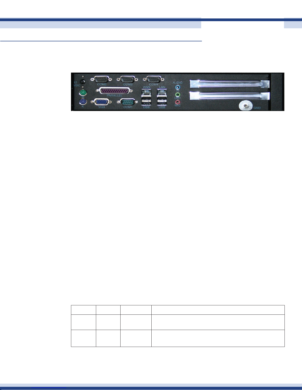
The rear panel of the Cortexa 7202 is shown below.
12VDC Power 12V DC power connection 12Volt 5 Amp (included)
K PS2 keyboard connection. Used only to reset the device back to factory
defaults
M Mouse connection. Not used
Com 1,2,3,4 Used to connect sub-systems
USB Two USB ports. Used to connect to USB-RS232 adapters for further
7
expansion
WAN Used to connect to a broadband connection (connects to Cable/DSL
modem)
LAN Used to connect to a local area network switch
VGA Monitor connection. Used only to reset the device back to factory defaults
Parallel Used to connect an 8-port parallel relay board
Out, In, Mic Audio connections are used for the built-in Cortexa Audio player
Gnd Used to ground the Cortexa
All network ports are 10/100 Mbps Ethernet. Each port supports only unshielded twisted
pair (UTP) cable using an 8-pin RJ-45 plug with standardized T568A or T568B Terminations.
Each port uses RJ-45 connectors that have two LEDs. The network access speed is automatically
sensed and displayed by the left or FDX LED color. The right or LINK LED is solid green when
properly linked to another network device and blinks during network activity.
Label Color Activity Description
FDX
Green
YellowOnOn
Link Green Blinking
The port is Linked and operating at 100 Mbps
The port is Linked and operating at 10 Mbps
Packet transmission or reception is occurring on the
port
Version 2.2
Page 8
GettinG to Know the Cortexa 7202
Continued
n front Panel
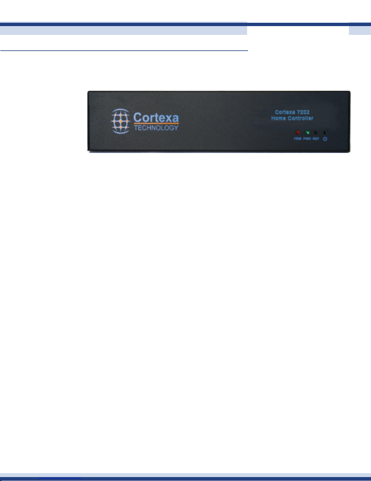
The front panel of the Cortexa 7202 is shown below.
FRW Indicates ash memory read/write activity
PWR Power on/off indicator
RST Resets the Cortexa
PWR SW Turns the Cortexa on/off. To turn off hold for four seconds
8
Version 2.2
Page 9

installinG and ConfiGurinG the system
A basic understanding of networking and the connected sub-systems is highly recommended
to ensure a smooth installation of this product. All systems connected should be installed
according to the respective manufacturer’s recommendations.
In addition, ensure qualied personnel are used to install equipment where required. For
example, a licensed electrical contractor will be required to install all line voltage devices
such as light switches, and a licensed security contractor will be required to install or modify
your security system.
The following is an overview of the basic steps in setting up a system for the rst time. More
detail is provided in the respective sections of this guide. It is important that you follow the
steps below in order to ensure the installation goes smoothly.
n Pre-wiring
9
Ensure all pre-wiring is in place, based on which sub-systems you intend to automate. Pre-
wire requirements for all sub-systems are detailed in the Cortexa Pre-Wire Guide, available
from www.cortexatechnology.com.
n installing sub-system deviCes
Physically install all sub-system devices. Here we are talking about security systems, lighting
devices, thermostats, irrigation modules, surveillance cameras, audio system.
Be sure to ensure all sub-systems and devices are working satisfactorily before you start
integrating them into your Cortexa distribution system, etc.
n ConneCting to the Cortexa 7202
Physically connect the RS232 connector for each of the following sub-systems (Security,
Lighting, Irrigation, HVAC, Audio), as applicable in your case, to a Com port on the back
of the Cortexa 7202. It does not matter which sub-system connects to which port, however
note which port each sub-system is connected to for the next step in the process. The only
exception to this is HVAC, which must be congured to Com1, 2, 3, or 4.
Version 2.2
Page 10

installinG and ConfiGurinG the system
Continued
n ConneCting the Cortexa to the network
This step establishes the Cortexa to your network and the accessibility to the Internet. In
most cases, the Cortexa will come plug and play out of the box, without requiring any
network conguration. If this is not the case, refer to Section 4, Initial Network Setup, for
more information.
n Configuring the sub-systems
From the Sub-System Setup tab on the Conguration Utility Page, congure each sub-system
to the Com port to which it is physically connected. Com ports are selected by clicking on
the drop down box beside the port. This will display all available Com ports. Simply click
on the Com port desired and the Cortexa will then recognize that particular sub-system.
n setting uP the sub-systems
Within each sub-system, all of its specic devices must then be added to the Cortexa. This
10
is a simple process, and varies by sub-system. Details on how to do this are provided in the
section of this Owners Guide pertaining to each sub-system. The following is an overview by
sub-system to help explain what information and conguration we are talking about here.
Security: Security zone information is entered into the Security Manager
HVAC: Each thermostat must be physically congured to have a unique address and
entered in the Device Manager
Lighting: Specic lighting devices are congured into Areas (Rooms) in the Cortexa
Device Manager
Irrigation: Irrigation zones are added to and labeled in the Cortexa Device Manager
Cameras: Names associated with each camera must be assigned and entered into the
Cortexa Camera Manager
Audio: Zone names and source names are congured into the sub-systems setup
page (advanced button)
IR Control: Infra-red (IR) codes are learned into the Cortexa Device Manager (IR), and
custom remote controls are congured in the Device Manager
Version 2.2
Page 11

installinG and ConfiGurinG the system
Continued
n writing events
When everything is congured in the Cortexa Conguration Utility, you are ready to start
writing events. This is the fun part, where the system starts to come alive and automate your
home. The extent to which you can have the system automate the sub-systems in your home
is limited only by your imagination and creativity, so many scenarios are possible.
The way to think about your new integrated home is that every device congured into
the Cortexa is “connected” to every other device. So, thermostats, lights, security zones,
cameras, audio, TVs/DVDs (through IR control) are “connected” – your vision of living in a
digitally connected home is becoming a reality.
Here is one simple example of the integration of the sub-systems. Think about all the things
you do when you go to bed at night; arm the security system, turn lights off, check garage
doors are closed, adjust thermostat(s), turn TVs and other devices off. With one simple event
11
in the Cortexa, just arming the security system will trigger all of these other things to happen
automatically, within seconds.
Event writing is simple; there is no programming language to learn. Events are written using
selections provided in drop-down boxes and we feel sure you will easily master writing your
own events.
Be sure to name your events logically so you can easily identify each event and remember
the function that each event performs.
There is a detailed section on event writing, including several sample events, in the Home
Management section of this Owners Guide.
Version 2.2
Page 12

initial networK setup
n setuP your loCal area network (lan)
First, connect the broadband modem to the WAN port on the back of the Cortexa 7202.
A PC should then be connected to a port on a network switch, and the network switch
connected to the LAN port of the Cortexa. You will use standard Category 5, or better,
cables to do this. The link light for each port will be lit when you are properly connected
and all devices are turned on. A direct connection may also be made from the Cortexa LAN
to a PC, however this requires Cat5 crossover cable.
n start uP sequenCe
Power up your broadband modem rst and wait approximately one minute for it to
1.
complete diagnostics as indicated by the panel lights. If you have been connected
to another router previously, make sure to leave the modem power off for 1 to 2
minutes to refresh the router table.
After your modem is ready, start the Cortexa 7202 by pushing the power button.
2.
12
Wait approximately 2 minutes for the operating system to load.
Start your Computer. When ready, open your Internet Explorer web browser.
3.
n logging into the Cortexa
The Cortexa factory default settings issue DHCP addresses for the default gateway IP range
that is 192.168.10.100 to 192.168.10.150. If your computer is congured to receive a
DHCP address then you should have received an address in that range. If it is not congured
to receive a DHCP address, then you can manually set your IP address. Defaults for manual
TCP/IP conguration are as follows:
IP Address 192.168.10.x, with x being any number between 2 and 99
Subnet Mask 255.255.255.0
Gateway 192.168.10.1
DNS Server 192.168.10.1
Open your browser and enter the following into the address bar of your browser:
http://cortexa. This will take you to the login page. If not, try using http://192.168.10.1
If this does not work please see the troubleshooting section of this Owner’s Guide.
Version 2.2
Page 13
initial networK setup
n Configuring the router
This section details how to congure the Router within the Cortexa to manage your network
and gain access to the Internet through your Internet Service Provider (ISP). Your ISP may
require the use of a Host Name and Domain Name. You will need this information from
your ISP. If you do not have this information, please contact your ISP before proceeding.
Document any changes from default by printing the page before saving, and making notes
of passwords that are not displayed.
13
Continued
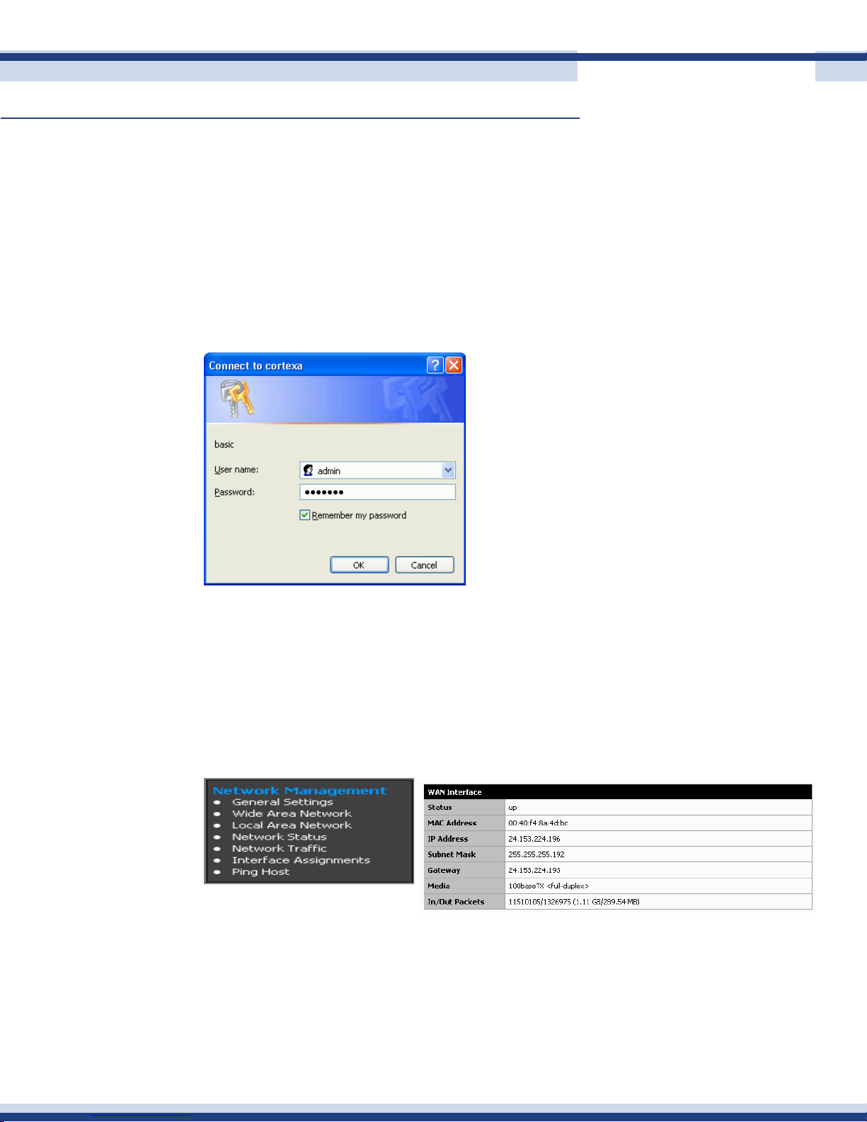
You will get a new login screen to gain access to the Cortexa 7202 Conguration Utility. Use
the same User name and Password as above. You will now be in the Cortexa Conguration
Utility. On the left of the screen each menu section will be highlighted in Blue with sub pages
below. Click on Network Management Network Status.
The Cortexa 7202 WAN Interface Status will appear at the top of the page.
You should now be at this login page. Enter admin
You should now be at this login page. Enter admin
in the User Name eld, and cortexa (the default
in the User Name eld, and cortexa (the default
password) in lowercase letters in the Password
password) in lowercase letters in the Password
eld. Optionally click on the box to remember
eld. Optionally click on the box to remember
this password for subsequent logins with this user
this password for subsequent logins with this user
name. Then click OK.
name. Then click OK.
The Cortexa My Home Home Page will appear.
The Cortexa My Home Home Page will appear.
Click on Settings Setup.
Click on Settings Setup.
If the IP address has a valid address then you should be able to connect to the Internet.
Open another browser window and try to log on to a site you don’t normally visit, to avoid
loading a cached page.
Version 2.2
Page 14
initial networK setup
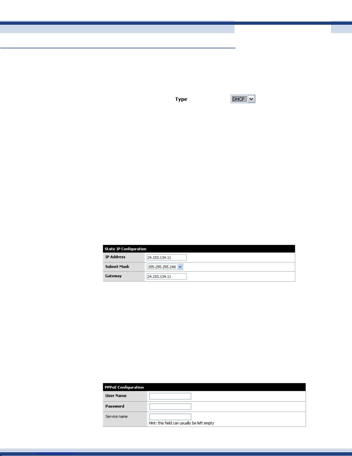
dhCP
If you are connecting through DHCP or a dynamic IP address from your ISP, perform these
steps:
Select DHCP as the TYPE.
1.
Click the Save button to save this setting.
2.
statiC iP
If you are connecting through a static or xed IP address from your ISP, perform these
steps:
Select Static IP as the TYPE
1.
Enter the IP Address
2.
Select the Subnet Mask
3.
14
Continued
Enter the Gateway
4.
Enter the DNS in the 1, and/or 2 elds. You need to enter at least one DNS
5.
address
Click the Save button to save the settings
6.
PPPoe
If you are using DSL and are connecting through PPPoE and if you normally enter a user
name and password to access the Internet, perform these steps:
Select PPPoE as the TYPE
1.
Enter the User Name provided by your ISP
2.
Enter the Password provided by your ISP
3.
Optionally enter the Service Name
4.
Click the Save button to save the setting
5.
Version 2.2
Page 15
initial networK setup
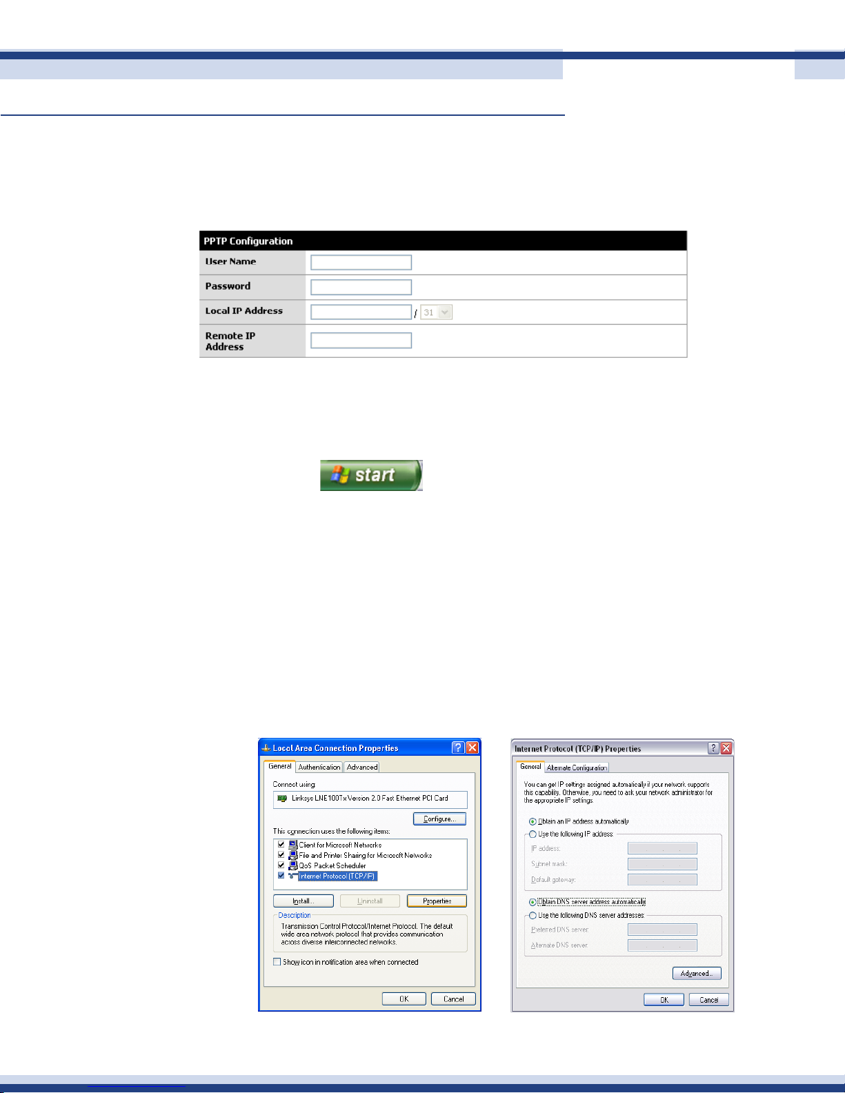
PPtP
PPTP is a service used mainly in Europe. If you are using a PPTP connection, check with your
ISP for the necessary conguration information.
n Configuring your PCs to ConneCt to the Cortexa 7202
Now that your router is congured, congure all PCs on the network to accept the IP addresses
that the Cortexa 7202 will assign.
15
Continued
Select the button, click Settings and open the Control Panel. From
1.
there, double-click the Network and Dial-up Connections icon. This will display the
Network screen.
Right click on Local Area Connection icon for the applicable Ethernet adapter
2.
(usually it is the rst Local Area Connection listed), then select Properties.
In the Conguration window, select the Internet Protocol (TCP/IP) and select
3.
Properties.
Select Obtain an IP address automatically.
4.
Verify that Obtain DNS server address automatically is selected. Then click the OK
5.
buttons on this and subsequent screens to complete the PC conguration.
Version 2.2
Page 16
Cortexa 7202 ConfiGuration utility
n main menu
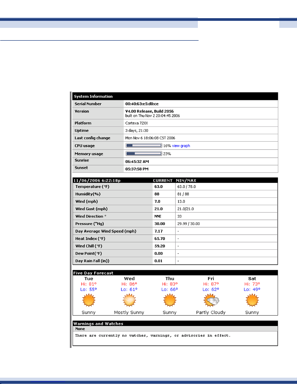
system information
The home page provides detailed system information. Here you see the resources that are
being used, the status of the Cortexa hardware, and weather data that is being received.
16
Version 2.2
Page 17

Cortexa 7202 ConfiGuration utility
Continued
Change Password
The password section allows the current user to change passwords. If logged in as admin,
this will change the admin password.
liCense keys
All access points other than a web browser require a License Key. All Cortexa access points
and access point software is shipped with a license key. This key is added in the License Keys
section of the Main Menu of the Cortexa Conguration Utility.
Click on the “+” button, enter the key and click Save. The key will then be added and
associated with the hardware device or software application. All keys are generic and
any key may be associated with any access point. Upon association, the parameters of the
access point will be listed; Key Date, Product, Version, IP Address, Report Date.
17
License keys may also be edited using the “e” button, or deleted with the “x” button.
n administration
The Administration section allows you to congure who has access to your Cortexa Home
Control system, and what permissions are allowed. This section is also used to update
rmware, and to backup and restore your settings.
user maintenanCe
Add a list of users that are allowed to access the Cortexa. This gives better security control
without having to give out the master password. This also provides the ability to determine
which, if any, of the conguration functions within the Cortexa each user may access.
baCkuP / restore
This section will allow you to back up and restore all of your settings. You should backup
your data after you have initially congured the Cortexa, and then at frequent intervals
thereafter. We recommend that you use the current date in the backup lename.
software uPdates
In our drive to continually improve this product, frequent software updates will be released.
All software updates are free to existing users, and easy to install. We want all users to
enjoy the latest software and the functionality and reliability it provides. First check to see
Version 2.2
Page 18
Cortexa 7202 ConfiGuration utility
Continued
if new software is available by clicking the Check Now button. If a later release of rmware
is available, simply click the Update Now button. The new software will now be downloaded
to your Cortexa. This will take approximately one minute. You will then be prompted to
reboot the Cortexa. Upon reboot, the new software will be installed and running.
reboot system
Select reboot system and click YES. A reboot will take approximately one minute.
faCtory defaults
If you require to restore the factory defaults settings, click the YES button. You will clear all
current Cortexa settings and restore factory default settings.
n home management
event manager
18
Events allow the automation of all sub-systems and devices throughout the home, in a
completely integrated way. This section will cover the key parameters involved in event
writing, followed by some examples to illustrate their uses.
Writing events with the Cortexa system does not require the learning of a programming
language unlike many systems. At every step, the system presents the user with valid choices
from drop-down menus. Do not think this is complicated, or beyond you. Many of our
customers start off saying they will not write their own events, then actually do when they
see how simple it is. Events may be written and executed from anywhere you have access
to your Cortexa.
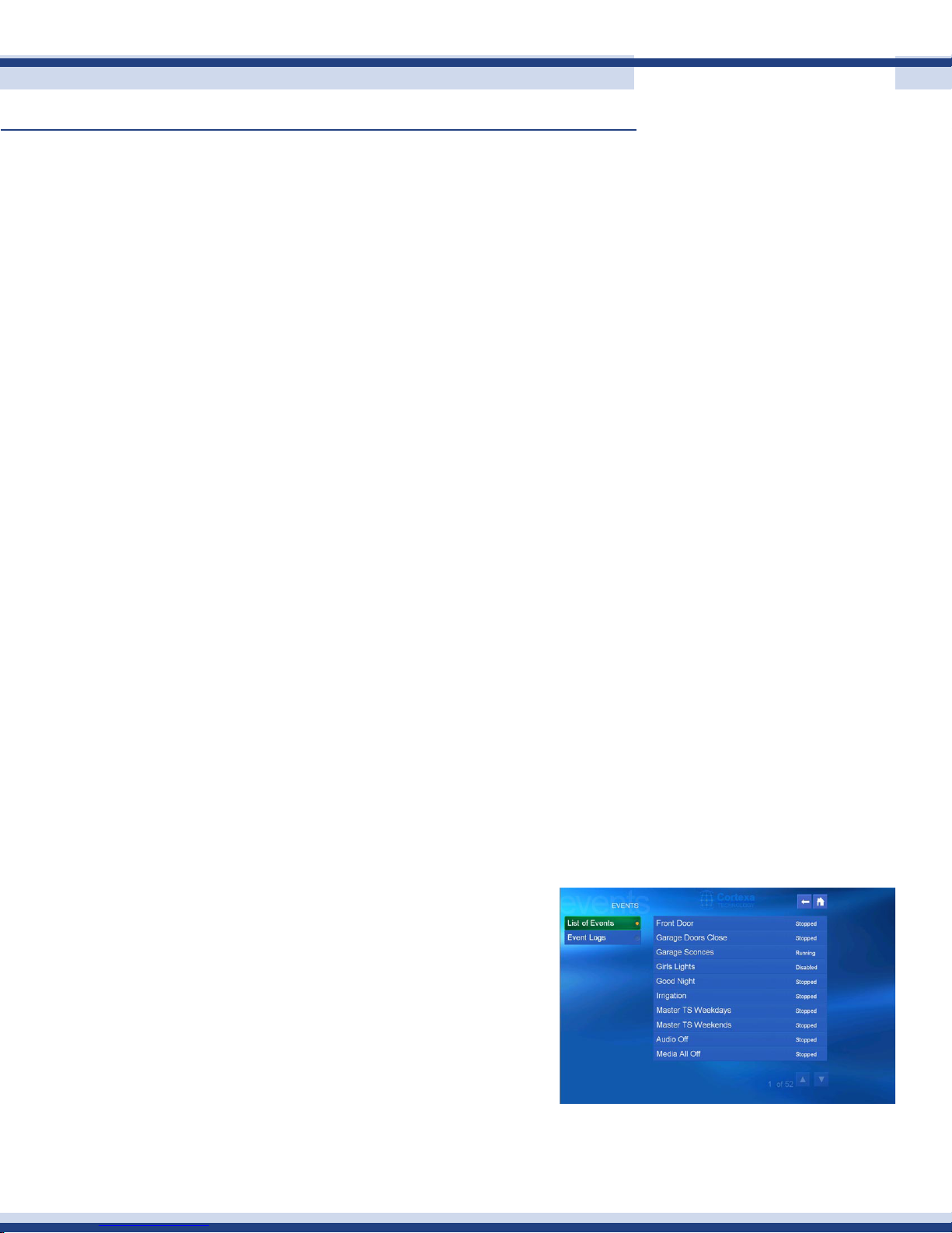
event user interfaCe
On the right is the Event page from the
Cortexa User Interface. From My Home,
you can view a list of all events within the
system, and run an event by pressing the
play button. You can also view the status
of an event, enable an event, or disable
an event. For example, you may have a
morning event that automatically turns on
music throughout the home at 6.30am every
weekday. On vacation days you may not want the event to run, so simply pressing disable
will stop the event from running until it is re-enabled.
Version 2.2
Page 19

Cortexa 7202 ConfiGuration utility
Continued
event management utility
Located in the Home Management section of the Cortexa Conguration Utility, the Event
Manager is used to create and modify events. To create an event, enter the desired event
name in the event description eld and click Add New Event.
Having created the event, you can then add a trigger (optional), case statements (optional)
and lines of macros to make the event carry out the desired function. You may rename or
delete events using the buttons beside the event name. There is also an option to hide or
show the event. If there is no need for the event to be visible on the main user interface, you
may want to hide the event in order not to have too many events on the user interface. This
is typically used for events that have a built-in trigger and will never require to be manually
triggered.
Events may be organized using the Organize Events function at the bottom of the events
19
page. To re-order an event, select that event in the left drop-down box, then select the
event above the desired destination from the right drop-down box. Click Move and the
event will immediately move to its new location. This will determine the order in which they
appear in the My Home user interface. You may wish to list events in alphabetical order, or
perhaps in the order of most frequent use.
Names, Triggers, Cases aNd aCTioNs
These are the four things to consider in event writing. Here’s what they are and how they
are used:
name
Each event must have a unique name. Be sure to name events with a name that indicates
what they do. For example, an event run before going to bed might be called “Goodnight”.
After a while you will have many events in your system.
Version 2.2
Page 20

Cortexa 7202 ConfiGuration utility
Continued
triGGer
Events may or may not have a trigger. The trigger is what will start the event running. There
are many possible triggers; time, sunrise/sunset, weather condition and so on. For example,
a lighting scene may be triggered by sunset. Most events have triggers. Without a trigger,
an event will only run when manually initiated. There are events where you will want this
to be the case. An example might be audio events. Other than perhaps turning on audio
when you wake in the morning, for the most part it will be a spontaneous decision to listen
to music throughout the home. But when that time comes, just start the event and the music
can be playing in every room, from the same or different sources, at the desired volume in
each room.
Case
Events may or may not make use of case statements. A case is a condition that will be tested,
then dependent on the outcome of the condition, the action will or will not execute. A good
20
example is with irrigation events. You have an event that turns on your sprinkler zones,
however you don’t want to water your yard if the wind is blowing at 25 mph just when you
are ready to water. The condition of the case would then be to check wind speed. We will
look at this specic example later in this section.
aCtion
All events will have at least one action statement. Without an action statement an event
would not perform any function. Action statements will typically involve one or more devices.
For example, turn light(s) on, set thermostat temperature, set audio source, record video
from a camera. There are also situations, such as having the system send you an email,
where no device is involved, however this is still an action.
Version 2.2
Page 21
Cortexa 7202 ConfiGuration utility
Continued
examples of eveNTs
Here we will look at four actual events to help you see how the above parameters work
together. In each case, we will explain what the event does, followed by screen shots and
some brief explanations of what each screen is doing. To create an event, simply go to
the Event Manager within Home Management, enter the name of the event in the Event
Description eld, and click Add New Event. You will then be able to congure the event
trigger, case and actions. Case and Actions are accessed through the “Edit Macro” button.
front door arChive
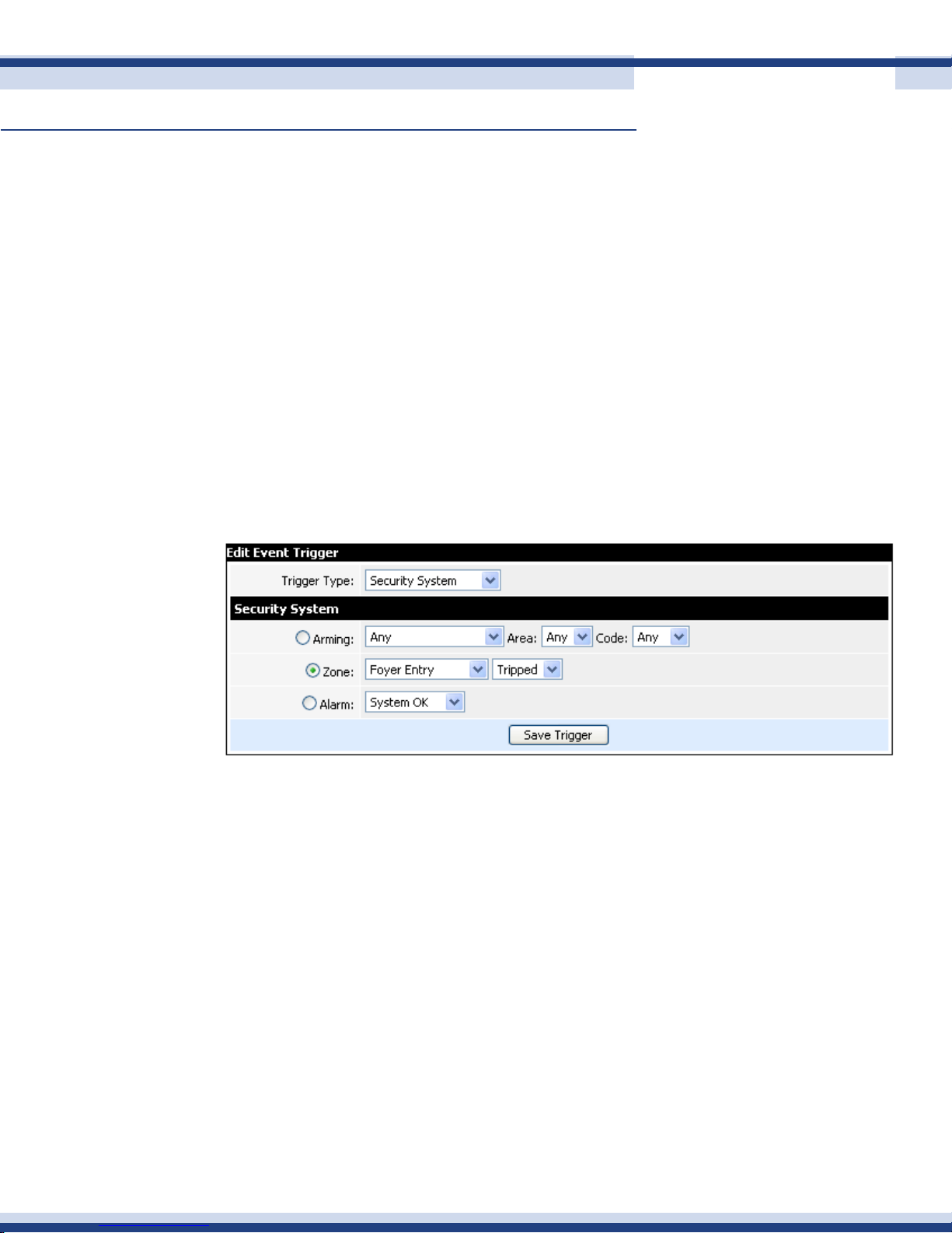
This event records video from a camera every time the front door is opened. Below is the
trigger. This is from the Security System, and specically the zone called Foyer Entry and
when the zone is tripped, i.e. the door is opened. Every time the door this opened, the
trigger will initiate this event.
21
Having established the trigger, we then think about whether we want to have a case condition.
In this situation, the answer is no. Every time the door opens, we want this to execute, so there
is no case involved. We then move to Action. This is where we tell the system what we want
the event to do, having been triggered.
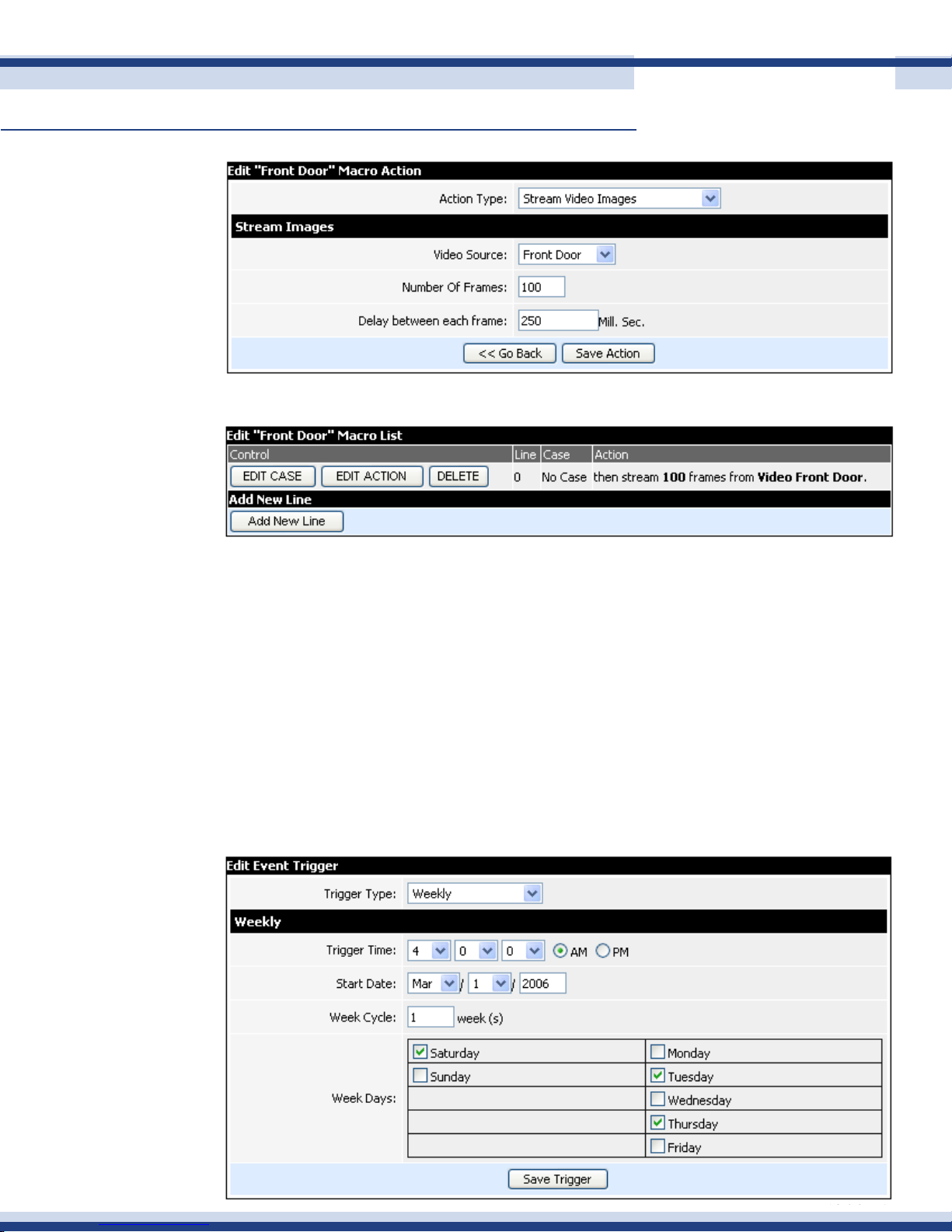
On the next page, you will see that in this case, our action is “Stream Video Images”, i.e. start
the camera recording. The system then asks which video source. We select Front Door (the
name of the camera over the front door). The system then gives us the option to select the
number of frames and the frame rate. These will obviously determine the quality and length
of the recording. Here we have selected 100 frames at 250 milli second (one quarter of a
second) intervals. This will give us 25 seconds of good quality video.
Version 2.2
Page 22
Cortexa 7202 ConfiGuration utility
Continued
The event is now complete and looks simply like this.
22
This is not a very complicated event, however we hope you can see how simple and fast it
is to create, and not one line of programming code involved! When you become procient
with the system, events like this can be created in just a few seconds.
irriGation
This event turns on two zones of irrigation, however we care about the environment (and our
water bill), so have added some intelligence in the form of two cases.
Firstly, the trigger. This is time based; specically we want to irrigate three days per week.
The trigger type is Weekly, and as you can see we have entered our desired parameters in
terms of which days and what time we would like to start watering.
Version 2.2
Page 23
Cortexa 7202 ConfiGuration utility
Continued
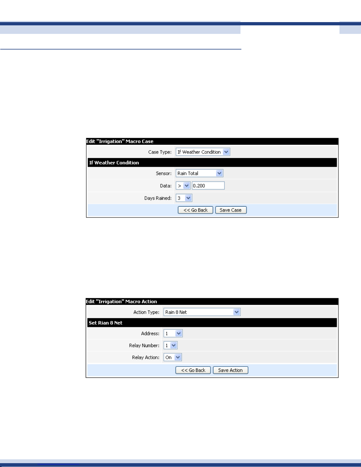
We now click Edit Case. In this situation, our case is a Weather Condition. That condition is
based on Rain Fall. Since the Cortexa is collecting local weather data every fteen seconds,
not only does it know current weather conditions, it is also able to calculate historical data.
We decided our criteria to be based on 0.2” over the last three days.
We also added another case condition based on current wind speed. You will see that when
we look at the nished event.
23
Having established our trigger and cases, we are ready for action. The action is to water
the yard. The Action type is “Rain 8 Net”, the name of our Irrigation system. The Irrigation
module comes in 8 zone increments, each one having a unique address. The relay number
then corresponds to the irrigation zone. Here we are turning on zone 1, i.e. Address 1, Relay
1. As an example, zone 9 would be Address 2, Relay 1.
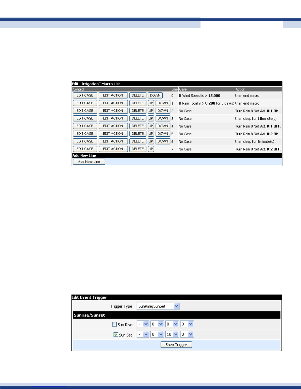
The following screenshot is the completed event. After each case statement, we selected
End Macro. End macro immediately halts the entire event, i.e. none of the actions commands
are executed. Obviously this is what we want here. If rst condition is true, i.e. the wind is
blowing at more that 15 mph, we do not want to water the yard, no matter what else is true
or false.
Version 2.2
Page 24
Cortexa 7202 ConfiGuration utility
Continued
The command “Sleep For” is used to let the sprinkler zone run. So for zone 1, we open it,
then the event goes to “sleep” for 10 minutes. After exactly 10 minutes, the event “wakes
up” and turns off that sprinkler zone.
24
sunset liGhtinG
This is a very simple event which we will use to highlight one of very useful features of
Cortexa event writing; the use of ags. Flags can be used within cases to add some form
of condition or additional intelligence to the event.
The event simply turns on our desired lights, to their desired intensity level, at sunset each
day.
Here we are using sunset as our trigger. We also have the option to set variances from
both sunrise and sunset. We have decided that we’d like the lights to come on before sunset
as at sunset it is already a little dark in the house. We can set variances + or – and with
hours, minutes and seconds. In this case we are telling the event to launch 10 minutes before
sunset.
Version 2.2
Page 25
Cortexa 7202 ConfiGuration utility
Continued
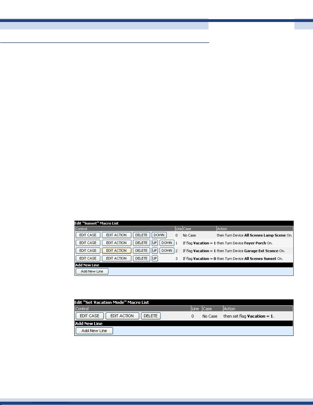
Our ag is called “Vacation”. Flags are setup up in the Flag Manager, again within Home
Management. Our vacation ag, as you might imagine, indicates whether we are home,
or on vacation. We would like a different lighting scenario to take place when we are on
vacation, i.e. less lights to come and not be wasteful of energy.
Flags have a value, which can set in the Flag Manager. They can also be modied by an
action in an event. In this case, we have the ag set up such that when we go on vacation
its value is 1, otherwise it is 0.
So let’s look at the event. Both “Lamp Scenes” and “Sunset” are pre-dened lighting scenes
that have already been set up. Line 0 in this event will always run, i.e. whether we are on
vacation or not, we want the lamps to come on.
Lines 1& 2 will run if we are on vacation (because the vacation ag will be set to 1), but
25
not if we are not.
Line 3 is the opposite of 1&2. It runs when we are home. This turns on lights throughout the
home, just as we want, but only if we are home!
To set the vacation ag, use a simple action statement as below.
Version 2.2
Page 26
Cortexa 7202 ConfiGuration utility
Continued
GoodniGht
This event runs last thing at night. We will use it to highlight another nice feature; the ability
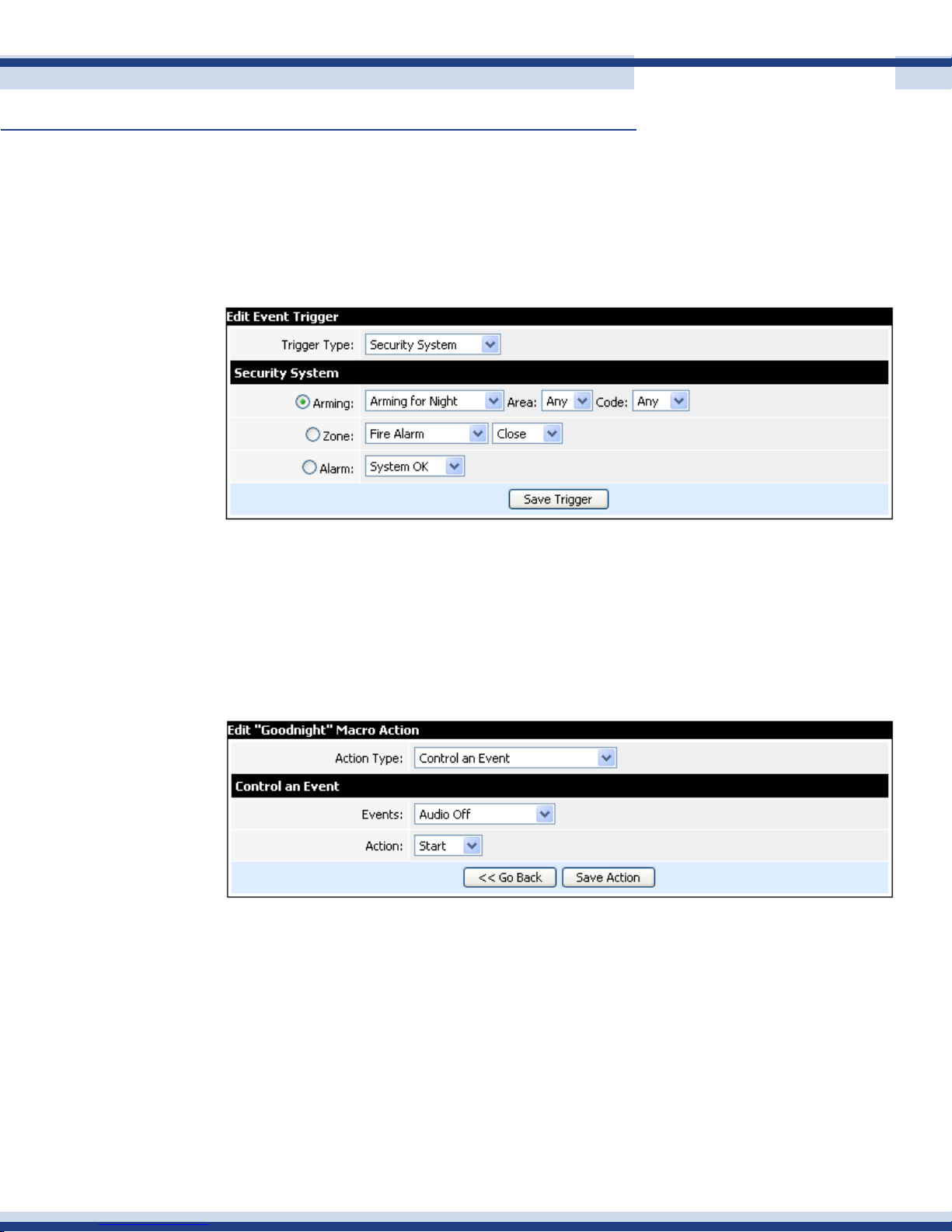
to run an event from within another event. The trigger is the arming of the Security System
with any user code. If you have multiple codes, you can write events specic to the code
used to arm, or disarm, the system.
26
We have an existing event called “Audio Off” that turns off all audio throughout the home.
We’d like to do that as part of this event. Instead of having to write the actions for that
event again, we simply select “Control an Event”. The system then prompts us for the name
of the event from a drop-down menu with the names of all of our events. We select “Audio
Off”, then tell the system to start the event.
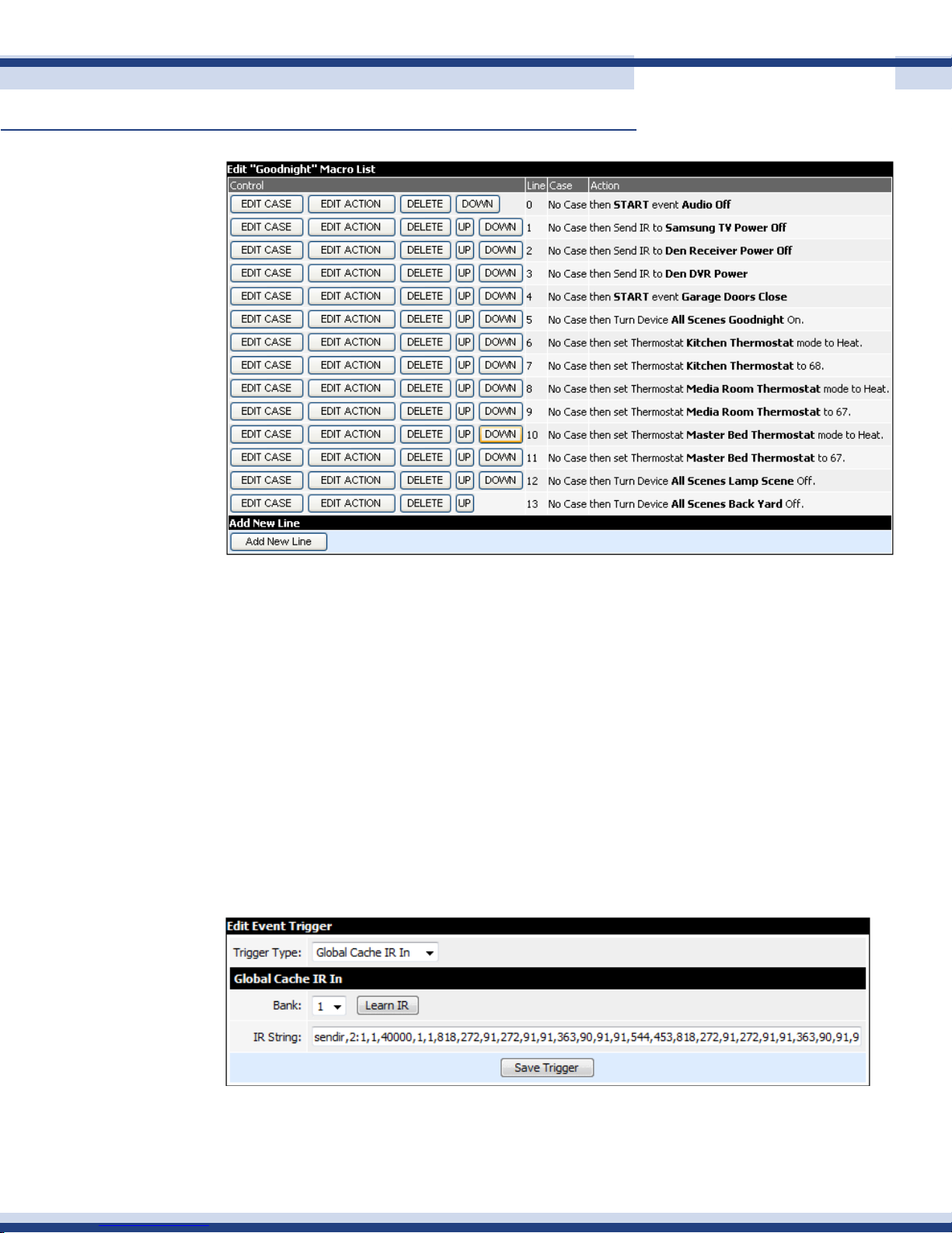
The entire event is below. After turning off our audio, we send commands to a TV, Receiver
and DVR to turn off. We then run another event that we have previously written, “Garage
Doors Close”. This event checks to see if all doors are closed and closes any that are open.
We then adjust three thermostats for comfortable sleeping temperatures, and nally run two
lighting actions to congure the lights how we like them during the night.
Version 2.2
Page 27
Cortexa 7202 ConfiGuration utility
Continued
27
A useful event trigger is an IR command. Essentially any button on an IR remote control can
be set to trigger any Cortexa event. For example, an unused button may be “mapped” to
the “Goodnight” event, shutting the house down for the evening from one button press.
The event is very simple to congure, essentially just a trigger and an action. On the trigger
page, the Learn IR button is used to capture the trigger IR. With the IR receiver attached
to the Global Cache device in line of sight to the remote control, click on Learn IR then push
the remote control button to be captured. The IR string will then be populated in the space
provided. Click on save and the trigger is complete. As with any other event, select the
desired action to be triggered. The event will now run every time the IR receiver detects
this IR command.
Version 2.2
Page 28
Cortexa 7202 ConfiGuration utility
Continued
deviCe manager
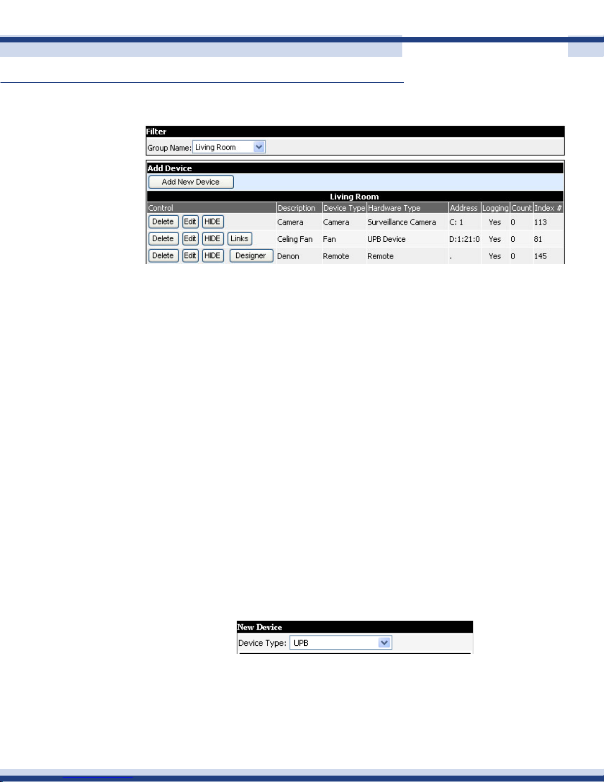
• Control: Enables selection of the module you would like to delete or edit
• Description: The description you give the device
• Device Type: The type of device that is being controlled
• Hardware Type: The type of hardware used
28
• Address: The current address of the hardware
• Logging: It will log the action to the log le, when an action from the module is
received
• Count: The number of times the device has been turned on
• Index #: The database index number
Each device added is associated with a room. In the My Home user interface under Rooms,
you will then see and have control of each device within that specic room.
It is possible to associate one device with multiple areas. This is useful for thermostats, for
example, where one thermostat may control multiple rooms.
ediT deviCe page
Once you click add new device, or edit device, you will be taken to the Edit Device Page.
If this is a new device, rst select the type of device to be added. The device types listed
will be determined by the sub-systems congured into the system.
Version 2.2
Page 29
Cortexa 7202 ConfiGuration utility
Continued
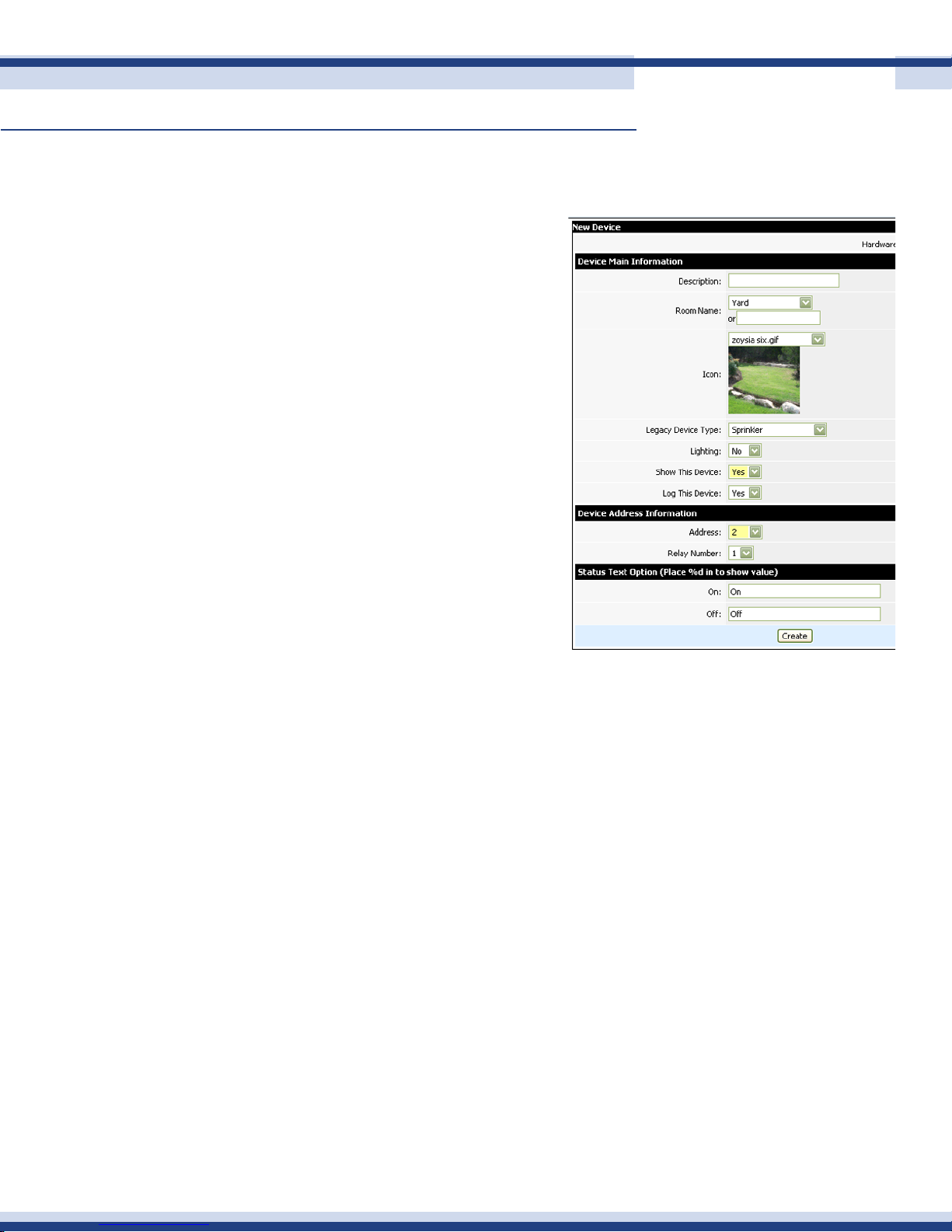
deviCe maiN iNformaTioN
Here you will enter information about the device:
• Description: This is what you wish the
device to be named. The number of
characters is limited in order that it
displays properly in My Home.
• Room Name: Select the room in
which the device is installed. If the
room does not yet exist, select New.
• Icon: Select a graphic to represent
the device or room.
• Lighting: Select Yes if you want to
see this device in the lighting section
of My Home.
29
• Show This Device: If you are using
My Home, you may disregard this
setting. If selected, the device will
be displayed in the My Home user
interface.
• Log This Device: If selected, the device will be logged every time it changes
status.
• Device Address Information: This is the conguration data associated with the
device. Required parameters will vary depending on the device type.
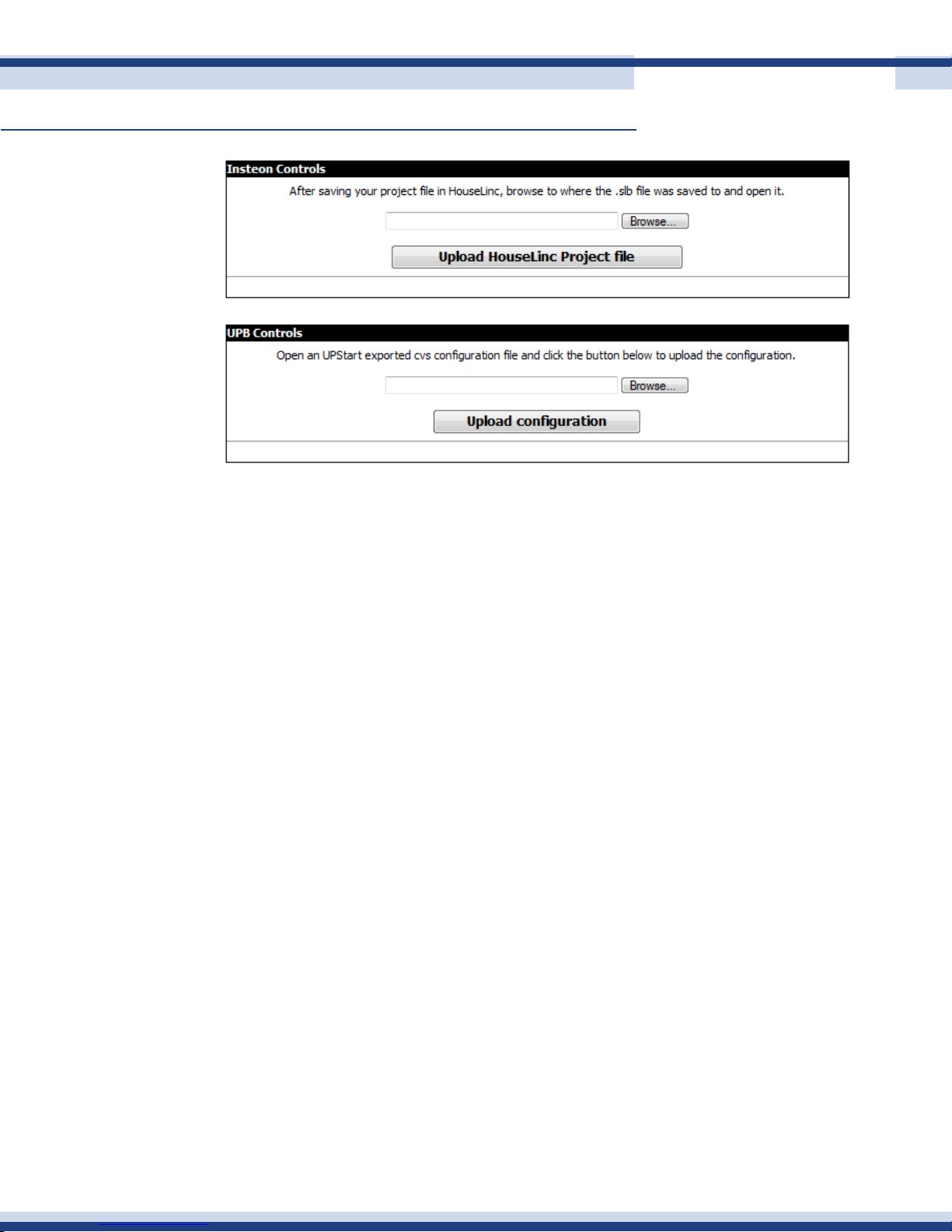
imporTiNg CoNfiguraTioN files from oTher appliCaTioNs
Insteon and UPB lighting systems offer conguration tools called Houselinc and UpStart
respectively. The Cortexa system is able to import the output of the these applications,
eliminating the need to create both individual lighting devices and lighting groups or
scenes.
The screen shot on the next page shows the simple import process. If Houselinc or UpStart
congurations are changed, a subsequent import will simply modify any devices that were
changed.
Version 2.2
Page 30
Cortexa 7202 ConfiGuration utility
Continued
orgaNize rooms aNd deviCes
The order in which both rooms and devices appear in the user interface may be altered
30
using this function. To re-order a device within a room, select that device in the left drop-
down box, then select the device above the desired destination from the right drop-down
box. Click Move and the event will immediately move to its new location.
To re-order rooms, select the rst device in the room from the left drop-down menu, then
select the rst device in the room above the desired destination from the right drop-down
box. Click Move and all devices within the room will immediately move to their new location.
This will determine the order in which rooms and devices appear in the My Home user
interface. You may wish to list rooms and devices in alphabetical order, or perhaps in the
order of most frequent use.
graPhiCs manager
This utility allows photos or other graphics to be uploaded to the Cortexa for use in the
representation of devices or rooms in the user interface. These custom images will be
displayed in the Rooms and Lighting areas of My Home.
The functionality of the utility, as well as the requirements for importing images is detailed
on the Graphics Manager page.
Images may be associated with devices using the Device Manager.
Version 2.2
Page 31
Cortexa 7202 ConfiGuration utility
Continued
deviCe manager (ir)
learNiNg ir CommaNds
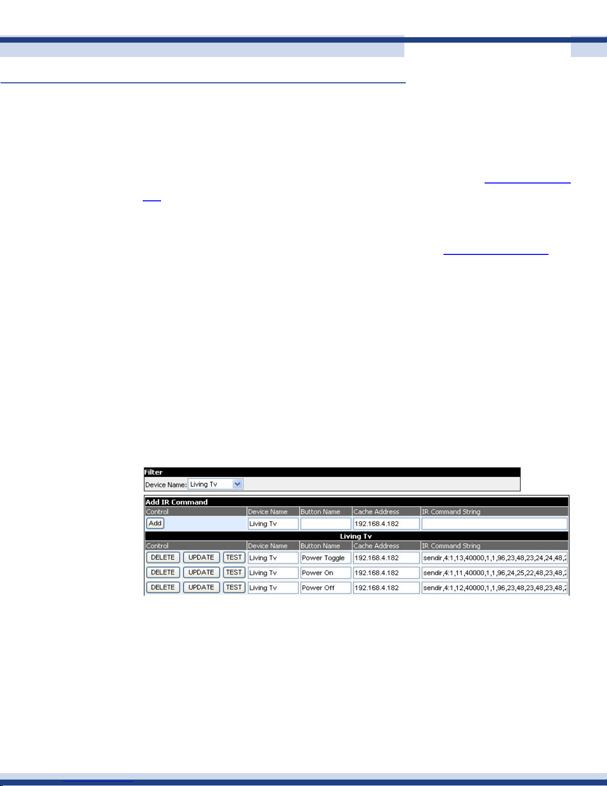
This section allows you to create a list of IR Commands to control your IR devices. If you have
not already done so, connect your Global Cache module to a network switch and congure
to a specic IP address. Details on how to set the IP can be found at www.globalcache.
com.
IR commands are learned using a Global Cache GC-IRL IR Learner. The IR learner is
rst connected to a PC through a serial interface. Then go to www.globalcache.com and
download the learner application to your PC. Launch the application, making sure you
see “connected” in the bottom bar of the application window. This indicates the Learner is
communicating with the PC serial port, and is ready to learn IR strings. Set the output type
to GC-100.
31
Now point your remote at the Learner and press the desired button. You will see the IR
string appear on the screen. This string is automatically in the clipboard. From there, go
to the IR screen below and simply paste the string into the eld. Make sure you name the
device to which the string relates and the specic button name. The more descriptive you
make these names; the easier it will be when you are recalling them to build a customized
remote control.
• Control: Enables selection of module you would like to delete or edit
• Device Name: The name of the device to be controlled
• Button Name: The name of the button to be controlled
• Address: The IP Address of the global cache device where the commands are
going to be sent
• IR Command String: The string that is created by the Global Cache IR Learner
Version 2.2
Page 32
Cortexa 7202 ConfiGuration utility
Continued
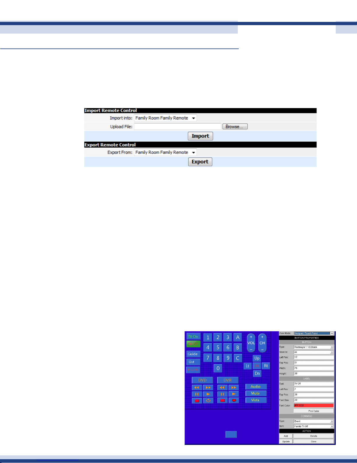
imporTiNg aNd exporTiNg remoTes
This function allows importing and exporting entire remote control congurations. Remotes
may be copied (imported) to another room within the current Cortexa system, or exported
to another Cortexa system. Once imported, the remote may be edited as normal.
BuildiNg a CorTexa remoTe CoNTrol
Building a remote control customized to your needs is easy with the Cortexa’s Remote
Control Designer. First go to Add Devices, add a Remote and associate it with the room of
32
your choice. Then go the Edit Devices, and beside the entry for that remote you will see a
button labelled Designer. This takes you into an application to congure a Cortexa Remote
Control.
Select View Mode. The rst selection is for both Media Center and a web browser, and the
second for a touch panel or webpad. These selections adjust the real estate available to
position remote buttons.
Below is an example of a remote controlling multiple components; TV, receiver, DVD, DVR,
PC, all from one single screen. Some of these buttons will send a single IR command to a
component, while others will execute an event.
The remote designer is very exible
with numerous variable parameters
to tailor buttons based on personal
preference; horizontal and vertical
positioning, size, text, font size and
color. Buttons may be dragged and
dropped anywhere on the screen.
Note: it is recommended that you
save the remote as you build it,
and obviously save it at the end of
the design.
Version 2.2
Page 33
Cortexa 7202 ConfiGuration utility
Continued
The Designer is highly intuitive and allows you to add buttons, either custom labeled or xed
such as Power, then drag and drop them to the desired position on the screen. You can
program any button to associate with any IR string you have learned, as above. Also, not
only can the remote activate an IR command string, it can also initiate any Cortexa event.
For example, in a home theatre setting, you might have an event that turns on a DVD player,
sets the channel on a receiver, dims lights and adjusts thermostat settings. This event could
then be activated by a “DVD” button on the custom remote. As you spend time creating
remotes, we think you will nd this functionality easy to use, exible and powerful.
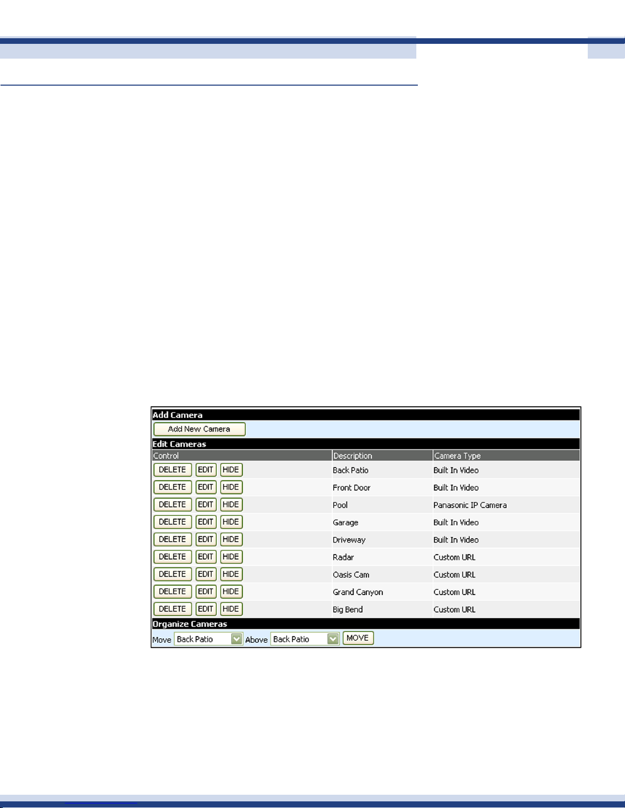
Camera manager
The edit video list page allows you to manage the video source.
• Control: Allows the video source information to be deleted, edited, hidden, or
shown.
33
• Description: A description of the video source.
• Camera Type: The template used to get camera images.
Version 2.2
Page 34
Cortexa 7202 ConfiGuration utility
Continued
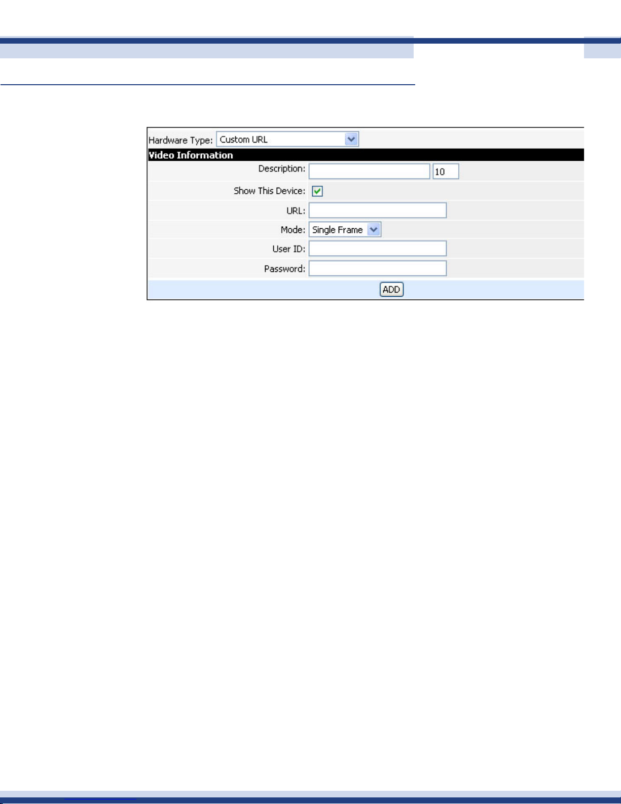
ediT Camera
• Hardware Type: Select camera type or a URL as the video source.
• Description: A description for the video source.
34
• Show This Device: This allows you to hide the camera from the My Home user
interface.
• Mode: Still images will take a single shot, and require a screen refresh to view a
new image, while Streaming will continually stream camera images.
• User ID: The user ID for the image source if required.
• Password: The password for the image source if required.
Note: If your Cortexa 7202 has a video server board installed, select Built In Video as the
Hardware Type. You will then enter the channel number for each camera.
orgaNize Cameras
Cameras may be organized using the Organize Cameras function at the bottom of the
page. To re-order cameras, select a camera in the left drop-down box, then select the
camera above the desired destination from the right drop-down box. Click Move and the
camera will immediately move to its new location. This will determine the order in which they
appear in the My Home user interface. You may wish to list cameras in alphabetical order,
or perhaps in the order of most frequent viewing.
Version 2.2
Page 35
Cortexa 7202 ConfiGuration utility
Continued
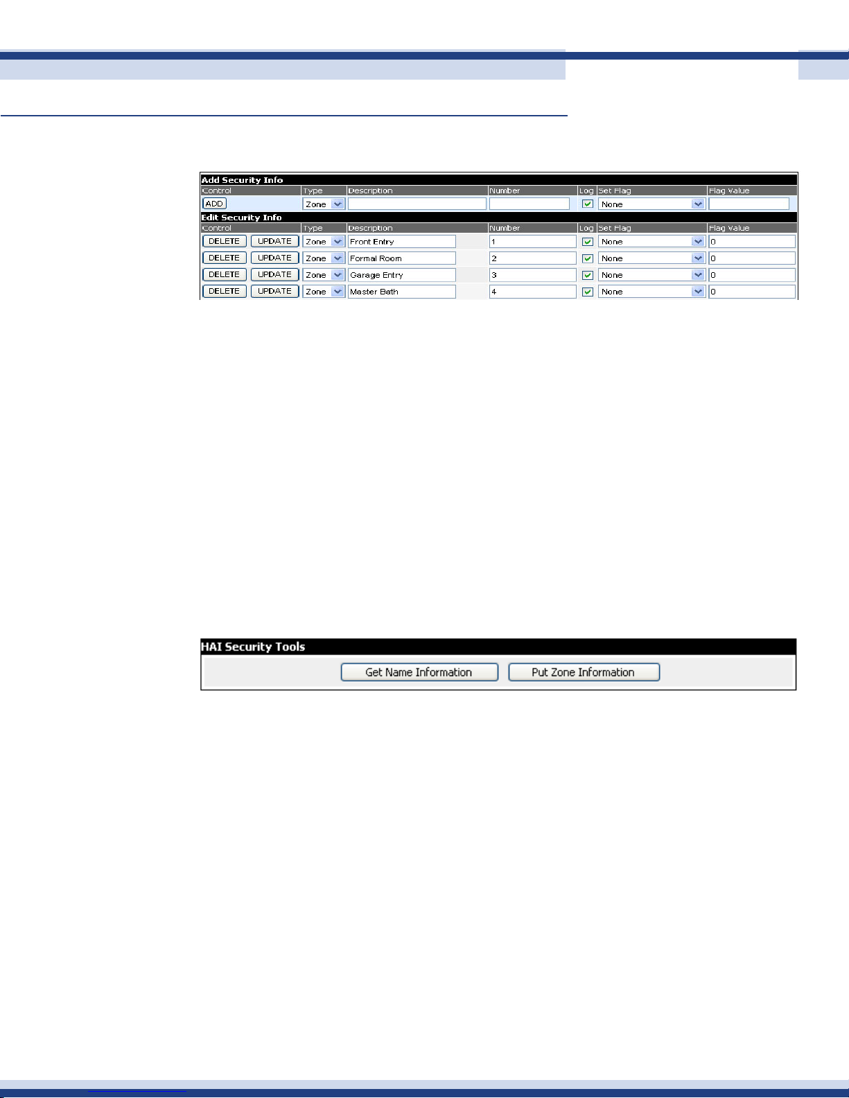
seCurity manager
The security system zone information from your security system is entered here:
• Type: The type of zone information
• Description: The name of the zone
• Number: What zone number this is associated with
• Log: Log this zone on activity. You may wish to not log motion sensors
• Set Flag: This is useful for events. For example, you can keep setting a ag to a
35
value as long as the activity is happening so that a light might stay on
• Flag Value: If setting a ag, this is the desired value to set the ag
hai seCuriTy Tools
If you have a HAI Omni security system, you can upload and download zone information
automatically between HAI Omni and the Cortexa 7202.
Click on Get Name Information to retrieve all zone and device data from the HAI system.
When retrieved, click Put Zone Information to automatically load the data into the Cortexa
Security Manager. All current security data will now be displayed in My Home under
Security.
flag manager
Flags can be useful with events. The Cortexa comes with 128 usable ags. There are two
types of ags; Static, and Second Counter. The Static ag is useful for status on something
that will have only two states, e.g. vacation mode. The Second Counter is useful for keeping
lights on for specic periods of time. The Second Counter is a down counter only.
Static ags are stored in ash memory, so if power fails, when the Cortexa comes back up it
will continue where it left off. Second Counters are not stored in ash, so when the Cortexa
comes backup, the current value will be set to 0. Once the down counter reaches 0, the
counter will stop.
Version 2.2
Page 36
Cortexa 7202 ConfiGuration utility
Continued
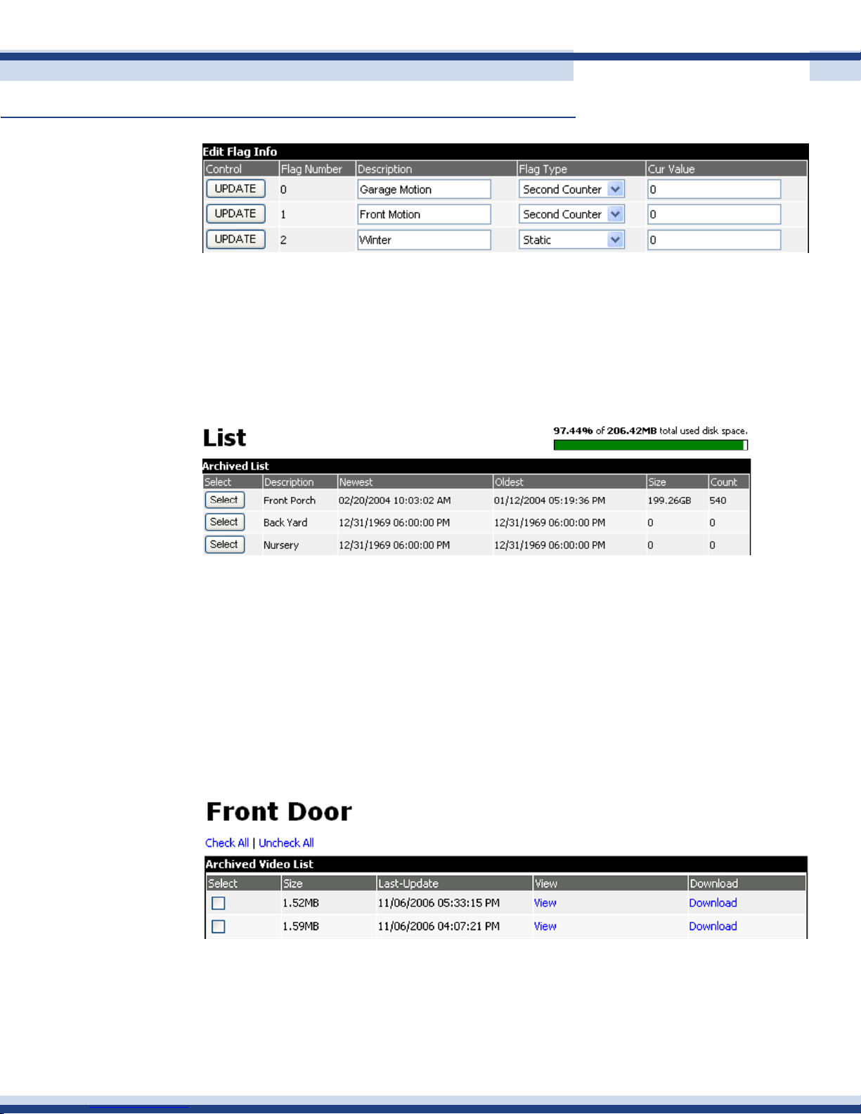
video arChives
This section allows you to view and manage the archived video stored on the built in ash
memory.
The bar graph (top right) shows how much disk space is left on the built in ash memory.
36
• Select: Allows you to select the camera to view
• Description: The name of the camera
• Newest: The time and date of the newest archive
• Oldest: The time and date of the oldest archive
• Size: The size of the archive le
• Count: The number of les stored for the specic camera
Once a camera is selected, you will see the list of archived les. You will be able to view
25 at a time.
• Select: Select the images to be deleted
• Size: The size of the image les
• Last-Update: The date and time of the last archive
• View: Click to view the archive
• Download: Click to download the archive to an alternative storage location
Version 2.2
Page 37
Cortexa 7202 ConfiGuration utility
Continued
n rePorting
deviCe logs
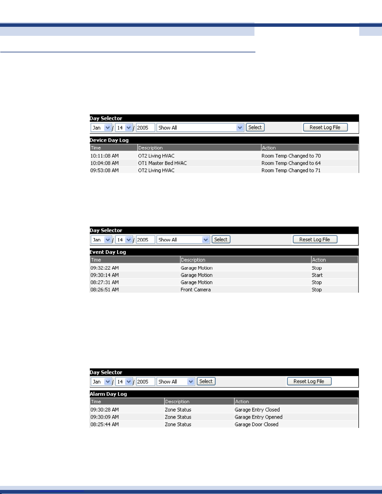
The device logs display all device status changes. The day selector may be used to go back
to a specic date to review the activity.
event logs
The event logs display all event activity and status changes. Again the day selector may be
used to go back to a specic date to review your activity.
37
seCurity logs
The alarm logs display all alarm status changes. Again the day selector may be used to go
back to a specic date to review your activity. As previously mentioned, you may want to
disable logging of high activity devices such as motion detectors. This is done in the Security
section by un-checking the Log Device box.
Version 2.2
Page 38
Cortexa 7202 ConfiGuration utility
Continued
system logs
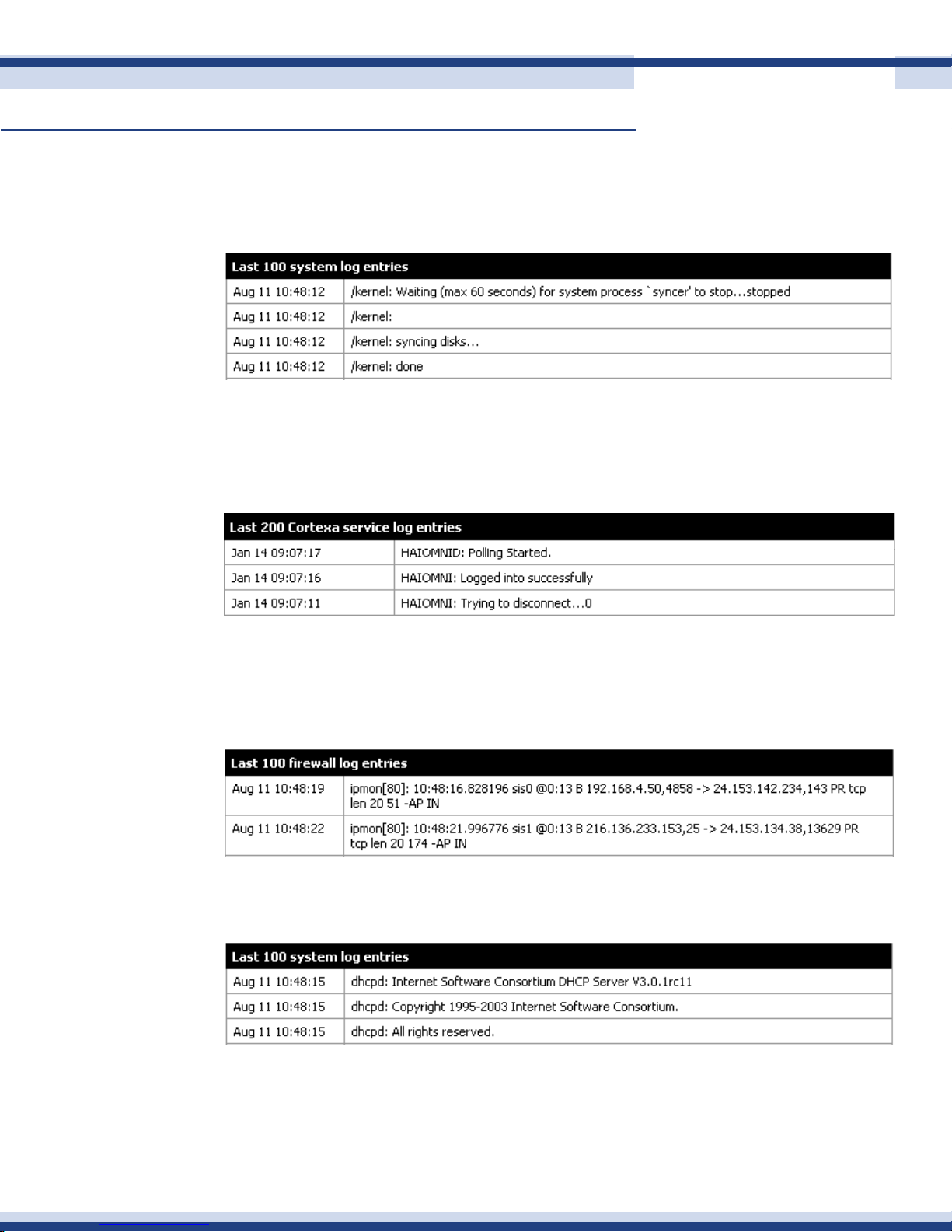
The system log is a list of warnings, and errors from the internal operating system. If a
problem arises, this is the most logical place to start trouble-shooting.
Cortexa logs
The Cortexa log will display any errors or warnings and errors coming from the home control
software.
38
firewall logs
The rewall logs show packets that where blocked by the rewall. Activity as below is
normal.
dhCP logs
The DHCP log shows the DHCP connections that are being requested by LAN clients.
Version 2.2
Page 39
Cortexa 7202 ConfiGuration utility
Continued
storage status
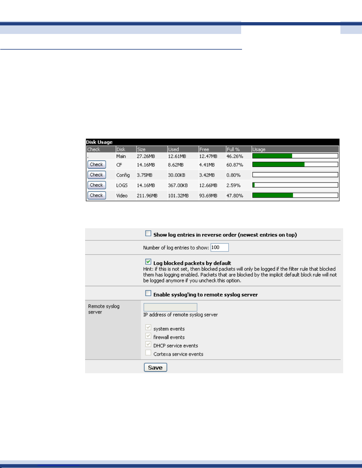
Shows the status of memory storage within the Cortexa 7202. Memory is split into several
partitions to keep write conicts down to a minimum. Most of the time the Cortexa does not
write to memory, so it is in read only mode. If logging information is being written to the
log partition, the Cortexa will only unlock the log partition to perform this operation, then
relocks the partition. This makes it safe to turn the Cortexa off without telling it to turn off. If
a power outage occurs, memory integrity should not be compromised.
39
rePorting settings
Version 2.2
Page 40
Cortexa 7202 ConfiGuration utility
Continued
n setuP oPtions
sub-system setuP
40
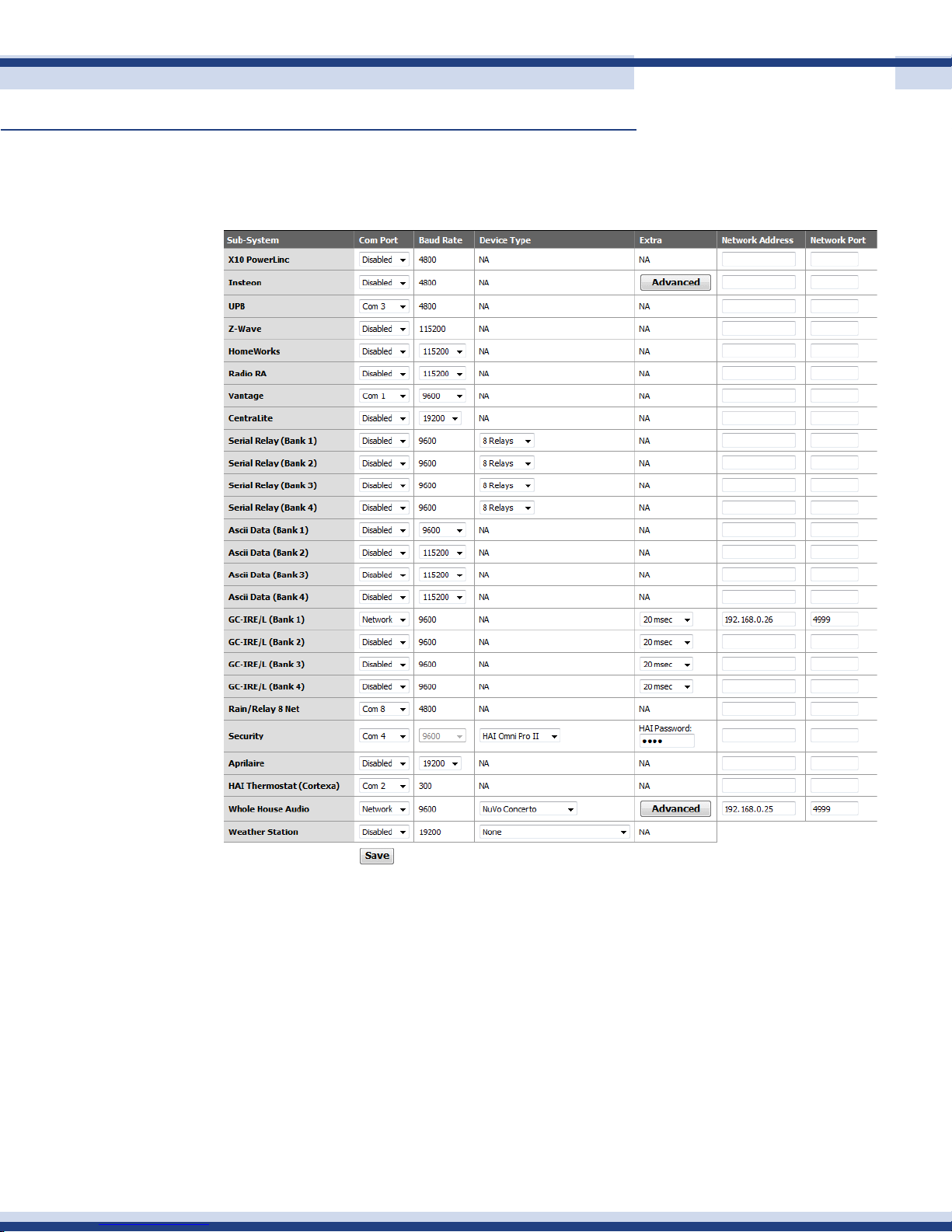
This section allows conguration of all sub-systems to the Cortexa controller. Any sub-
system may be congured to any Com port. The only exception here is HVAC, which must
be congured to either Com1, 2, 3, or 4. The port list will only show the available ports
attached to the Cortexa. The Cortexa 7202 comes with four ports, as standard with an
expansion board available to add another four, for a total of eight.
All sub-systems that are not congured into the system should be set to Disabled. Also
ensure that all required parameters are entered. For example, HAI security requires the
master security code to be entered. Some sub-systems may be congured to different baud
rates. In these cases ensure that the baud rate congured in the Cortexa matches that of
the actual sub-system, e.g. Vantage lighting controller. Lastly, click on Save after making
any conguration changes.
Version 2.2
Page 41
Cortexa 7202 ConfiGuration utility
Continued
The Ascii data sub-system is used where there is a need to have a RS-232 connection to a
device, but there is no sub-system interface built into the Cortexa. An example could be a
CE device such as a receiver or DVD player. In this case a physical RS-232 connection is
made between the device and the Cortexa and the Com port is congured appropriately.
The sending of the ascii data is then set up using events.
The GC-IRE/L sub-system is used to congure the Global Cache to be able to detect incoming
IR (a button press on a remote control. The conguration parameters are shown above with
the Com port set to Network and the IP address and port (4999) numbers of the Global
Cache devices being used entered in their respective boxes.
The application of this using the Global Cache controller is to enable buttons on IR remote
controls to run Cortexa events. For example, an unused button may be “mapped” to the
“Goodnight” event, shutting the house down for the evening from one button press. See the
41
Event Management section for more details on how to set up the IR trigger.
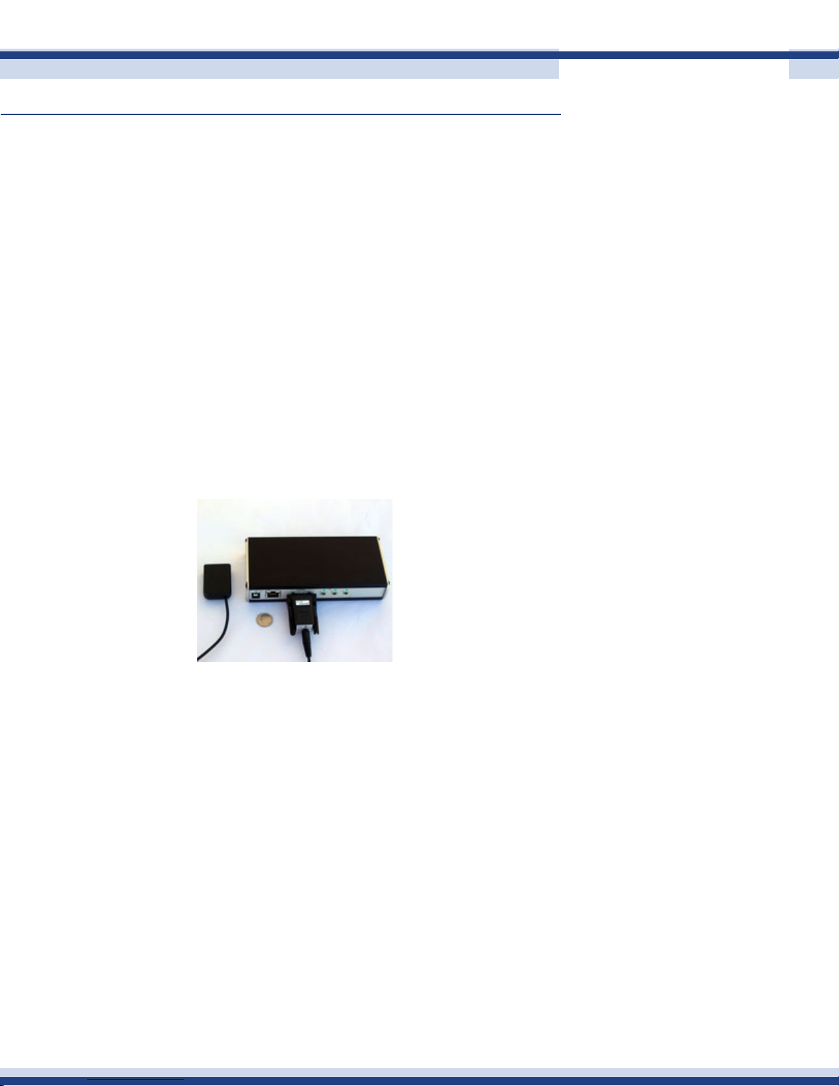
This functionality is achieved using a standard Global Cache network controller, with the
addition of two other pieces of hardware; the GC-IRE and the GC-RG1, shown above. The
IRE attaches to the Global Cache serial port and the RG1 plugs into the IRE. The RG1 is
an IR receiver and is used to receive the IR signal from the remote control which is then sent
through the Global Cache serial port to the Cortexa.
ConneCting to deviCes over ethernet
While most sub-systems are connected to the Cortexa Home Controller using RS-232
connections, the Cortexa software also supports the connection of devices over Ethernet.
Two such devices able to take advange of this are the Elk security system, and the Global
Cache network controller.
This effectively enables the RS-232 port on the device to be utilized as an additional serial
port. This may be particularly useful in situations where the sub-system to be connected is
Version 2.2
Page 42
Cortexa 7202 ConfiGuration utility
Continued
located close to the Global Cache device, e.g. audio distribution controller, but far from the
Cortexa controller.
The screen shot above shows Whole House Audio sub-system congured in this way. The
physical connection is therefore between the RS-232 port on the audio controller to the
RS-232 port of the Global Cache device. Above you can see how this is congured in
Sub-system Setup conguration page. The Com port is set to Network, and the IP address
and port number (4999) of the Global Cache to which the audio controller is connected are
entered. Some Global Cache devices have two serial ports, in which case the second port
number would be set here to be 5000.
email & weather
smTp server seTup
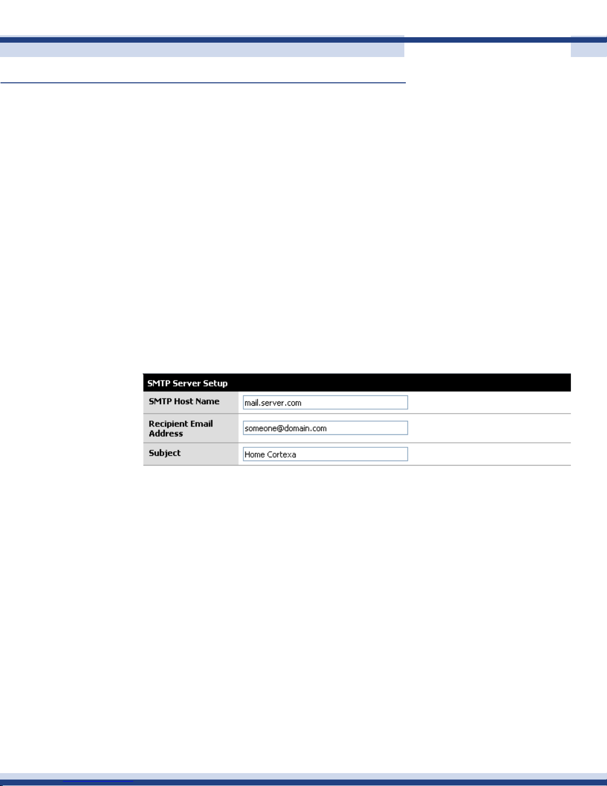
To utilize the Send Mail function within an event, email details must be entered here. Consult
42
your ISP if you do not have the required information.
• SMTP Host Name: The address to the SMTP server you are connecting to. This can
also be an IP address.
• Recipient Email Address: The E-Mail address that the email will be sent under.
• Subject: The subject line that will be sent with each email.
Version 2.2
Page 43
Cortexa 7202 ConfiGuration utility
Continued
WeaTher seTup
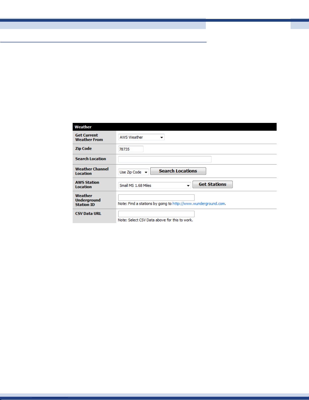
My Home has built-in a Weather function, with three pages of weather data for your selected
location; current weather, four day forecast and current weather alerts. All weather data is
obtained real time through the Internet.
The screen shot below shows varies options for the setup of Weather, depending on your
location and your preference on the source of weather data.
43
The conguration of weather sources is as follows:
Get Current Weather From
Select one of four options as your source of weather data:
American Weather Service (AWS) – data provided by the US Government service for US
only
The Weather Channel – world-wide data provided by TWC
Weather Underground – data captured from weather stations operated by companies or
individuals world-wide
CSV – used to utilize data from your own weather station and typically used in conjunction
with Ambient software and a web server
Version 2.2
Page 44
Cortexa 7202 ConfiGuration utility
Continued
ZIP Code
This is used by for US locations only Search Locations. Select the location you desire and
click save.
Search Location
This is used by The Weather Channel and supports world-wide weather. Enter city information,
select The Weather Channel as the source, then click on
AWS Station Location
If AWS is selected as the chosen source, click on Get Stations and a list of the closest weather
stations will be displayed. Select your desired station and click save.
Weather Underground
Determine the station ID of the desired weather station from the WU website, enter it into
44
the box provided and click save.
CSV Data
Enter the URL where CSV data is located. This is only used to utilize data from your own
weather station.
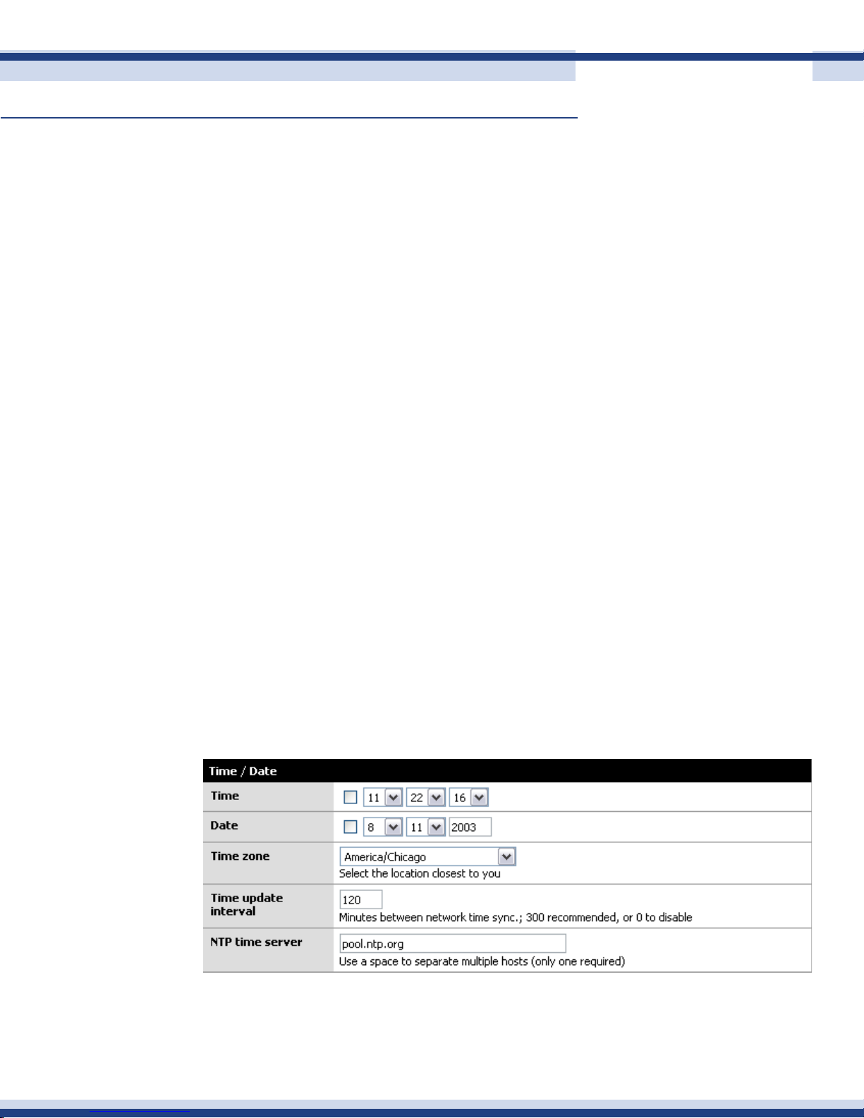
time & loCation
Set the current time, date and time zone for the Cortexa. Also, the location of an atomic
clock to keep the time synchronized. Note: if the NTP timer server is enabled, you will not
be able to manually set the time.
Version 2.2
Page 45
Cortexa 7202 ConfiGuration utility
Continued
• Time: Set the current time
• Date: Set the current date
• Time zone: Set the current Time Zone you are in
• Time update interval: How often the Cortexa will go to the Internet to get the
current time
• NTP Time Server: The time server from which the Cortexa sources time information
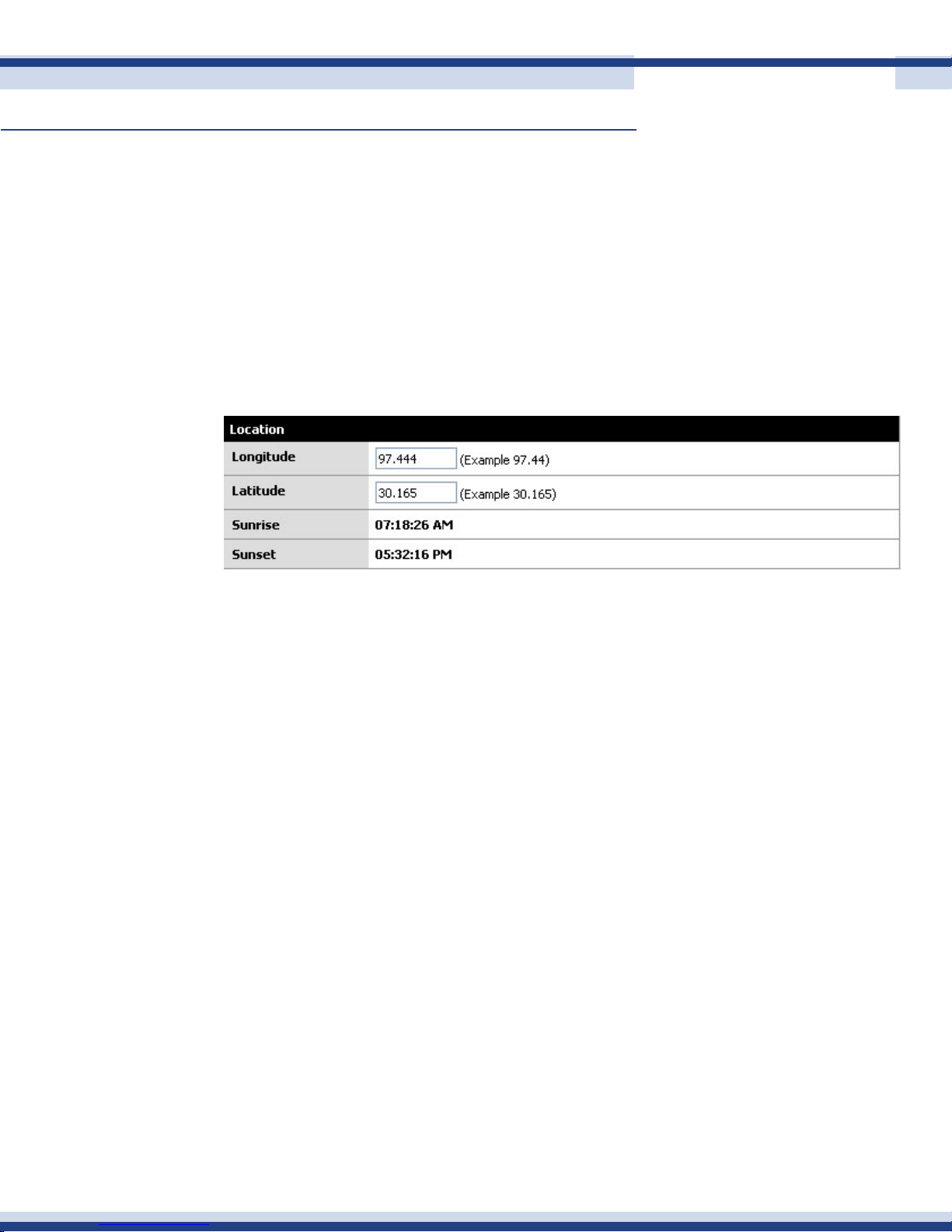
Setting longitude and latitude enables the Cortexa to calculate the current Sunrise and
Sunset time. Sunrise and Sunset are often useful triggers for events.
45
Version 2.2
Page 46
Cortexa 7202 ConfiGuration utility
Continued
n network management
general settings
46
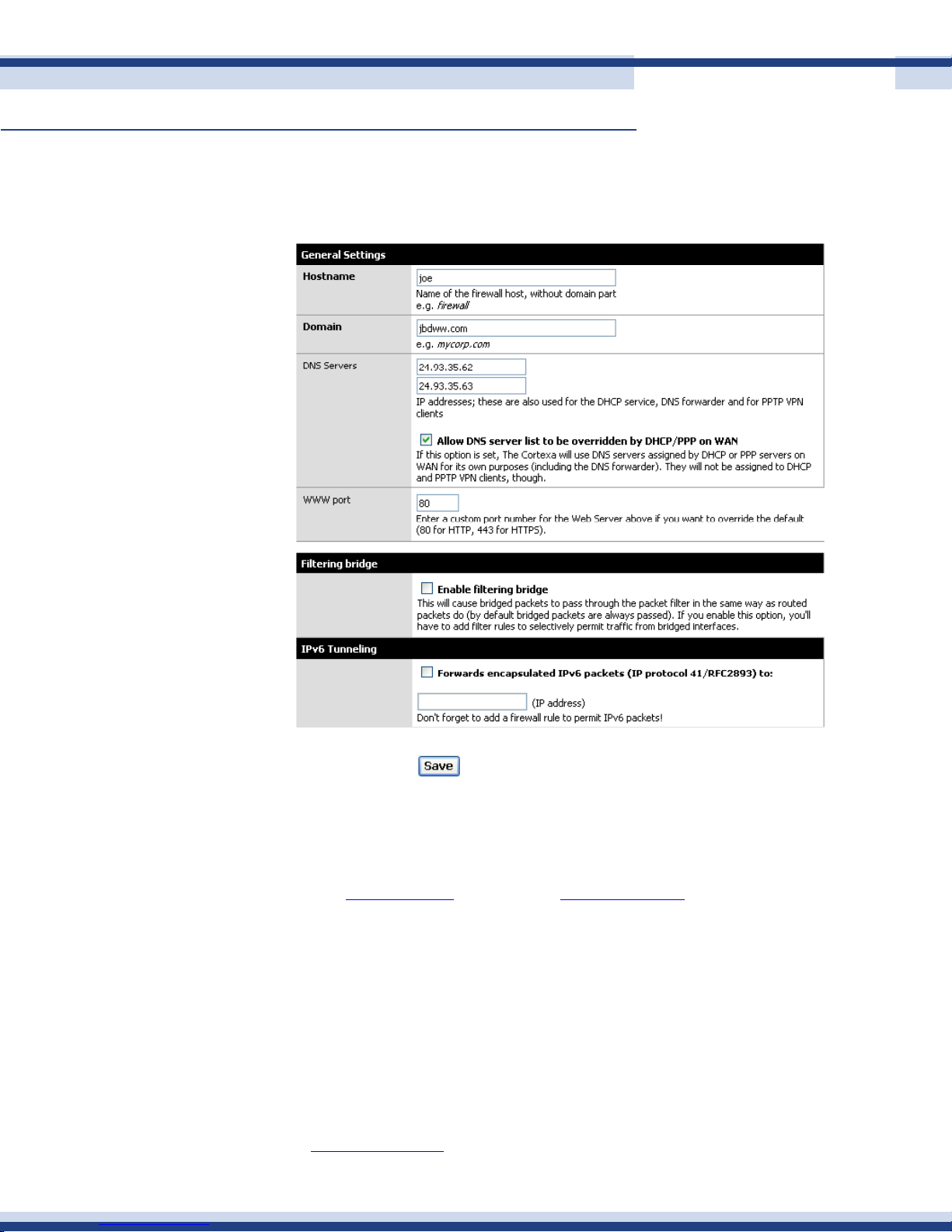
The general settings allow setup of the miscellaneous network information.
• Hostname: The name of the Cortexa 7202. Instead of connecting to the Cortexa
7202 as http://cortexa, you may use http://yourname. Note: The host name must
be all one word, no spaces
• Domain: The domain name with which the Cortexa 7202 is associated
• DNS The Domain Name System (DNS) is how the Internet translates domain or
website names into Internet address or URLs. Your ISP will provide you with at least
one DNS Server IP Address. If you wish to utilize another, enter that IP address in
one of these elds.
• WWW Port: The port number to connect to the Cortexa 7202. If using a port other
than 80 in the browser to connect, you must specify the port number. For example
use: http://cortexa:81 to utilize port 81.
Version 2.2
Page 47
Cortexa 7202 ConfiGuration utility
Continued
wide area network
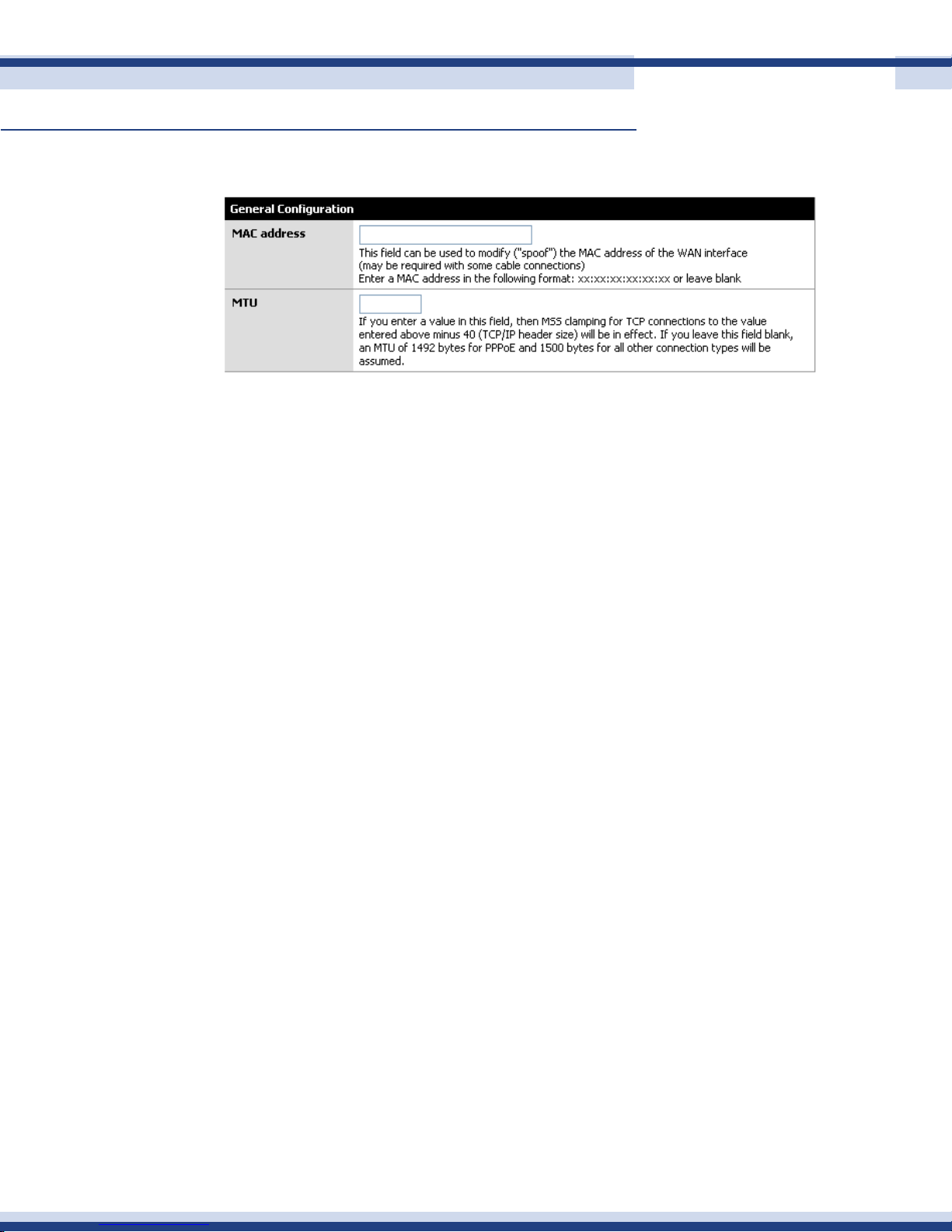
Media Access Control address: this is a hardware address that uniquely identies each
node of a network
With the MAC address eld, you can assign the Cortexa 7202 a MAC address, which is a
12-digit code assigned to a unique piece of hardware for identication. Some ISPs require
47
that you register the MAC address of your network adapter that is connected to your cable
or DSL modem.
Therefore, in order to connect the Cortexa 7202 to your cable or DSL modem instead of
the PC (network card or adapter), you must change the Cortexa 7202 MAC to duplicate
(or clone) your network card/adapter. You can nd your adapter’s MAC address by doing
the following:
• If you are running Windows 95,98 or Millennium: Go to the Start, Run, type in
command, and press Enter. At the DOS prompt type winipcfg
• If you are running Windows NT 4.0, 2000 or XP: Go to Start, Run, type in
command, and press Enter. At the DOS prompt type ipcong /all.
The Physical Address with 12 digits is your adapter’s MAC address. Enter those 12 digits
into the MAC Address elds, and click Apply. This “clones” your network adapter’s MAC
address to the Cortexa 7202, and prevents you from having to call your ISP to change the
registered MAC address to the adapter’s MAC address.
MTU is a limit, expressed in bytes, on the size of data sent over a network. It is the maximum
size of a single unit (e.g., an Ethernet frame) of digital communications.
Version 2.2
Page 48
Cortexa 7202 ConfiGuration utility
Continued
Type
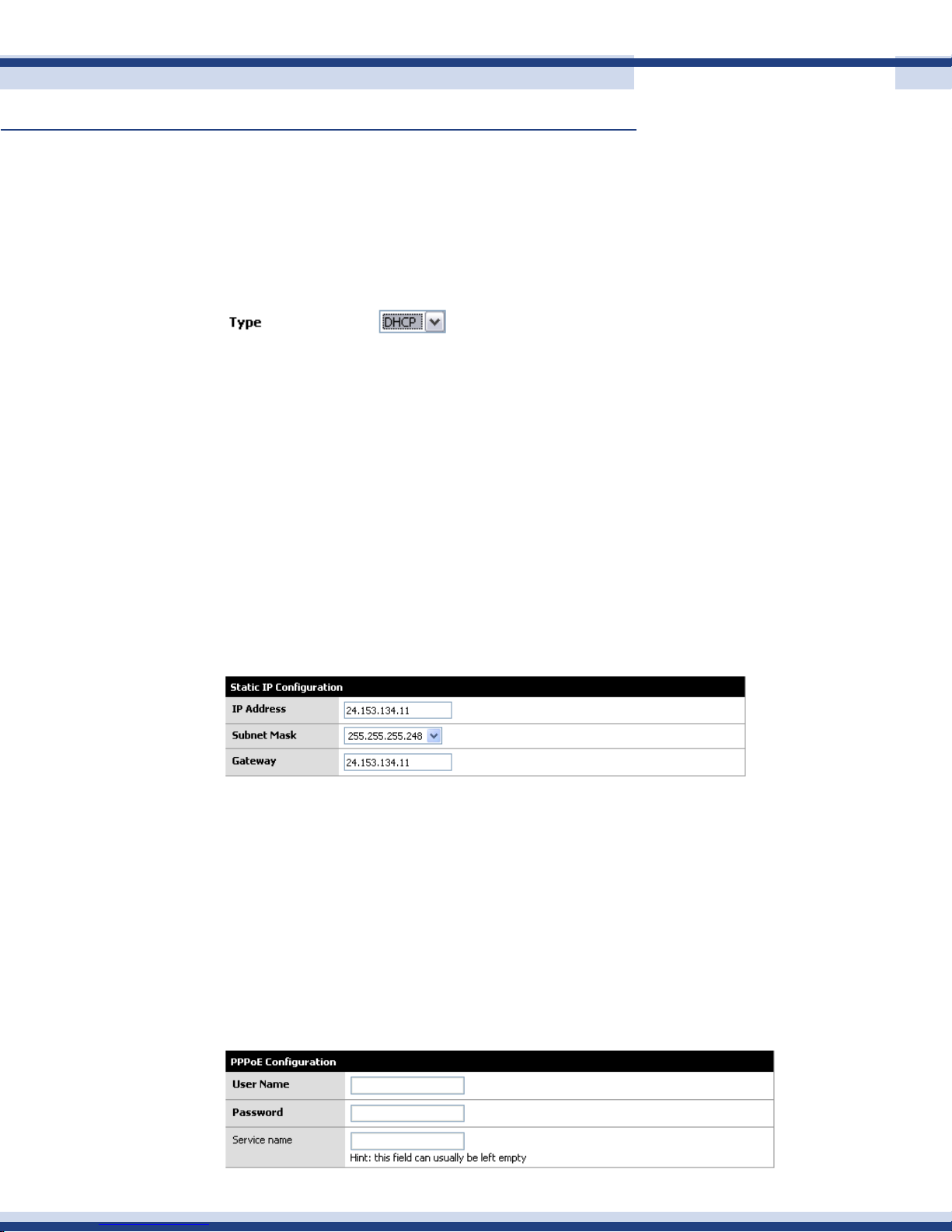
The Cortexa 7202 supports three connection types: DHCP (obtain an IP automatically),
PPPoE, Static IP Address, and PPPRP. These types are selected from the drop-down menu.
The available features will differ depending on what kind of connection type you select.
Each option is described below.
sTaTiC ip
If you are connecting through a static or xed IP address from your ISP, perform these
steps:
Select Static IP as the TYPE
1.
Enter the IP Address
2.
Select the Subnet Mask
3.
48
Enter the Gateway
4.
Enter the DNS in the 1, and/or 2 elds. You need to enter at least one DNS
5.
address
Click the Save button to save the settings
6.
pppoe
If you are using DSL and are connecting through PPPoE and if you normally enter a user
name and password to access the Internet, perform these steps:
Select PPPoE as the TYPE
1.
Enter the User Name provided by your ISP
2.
Enter the Password provided by your ISP
3.
Optionally enter the Service Name
4.
Click the Save button to save the settings
5.
Version 2.2
Page 49
Cortexa 7202 ConfiGuration utility
Continued
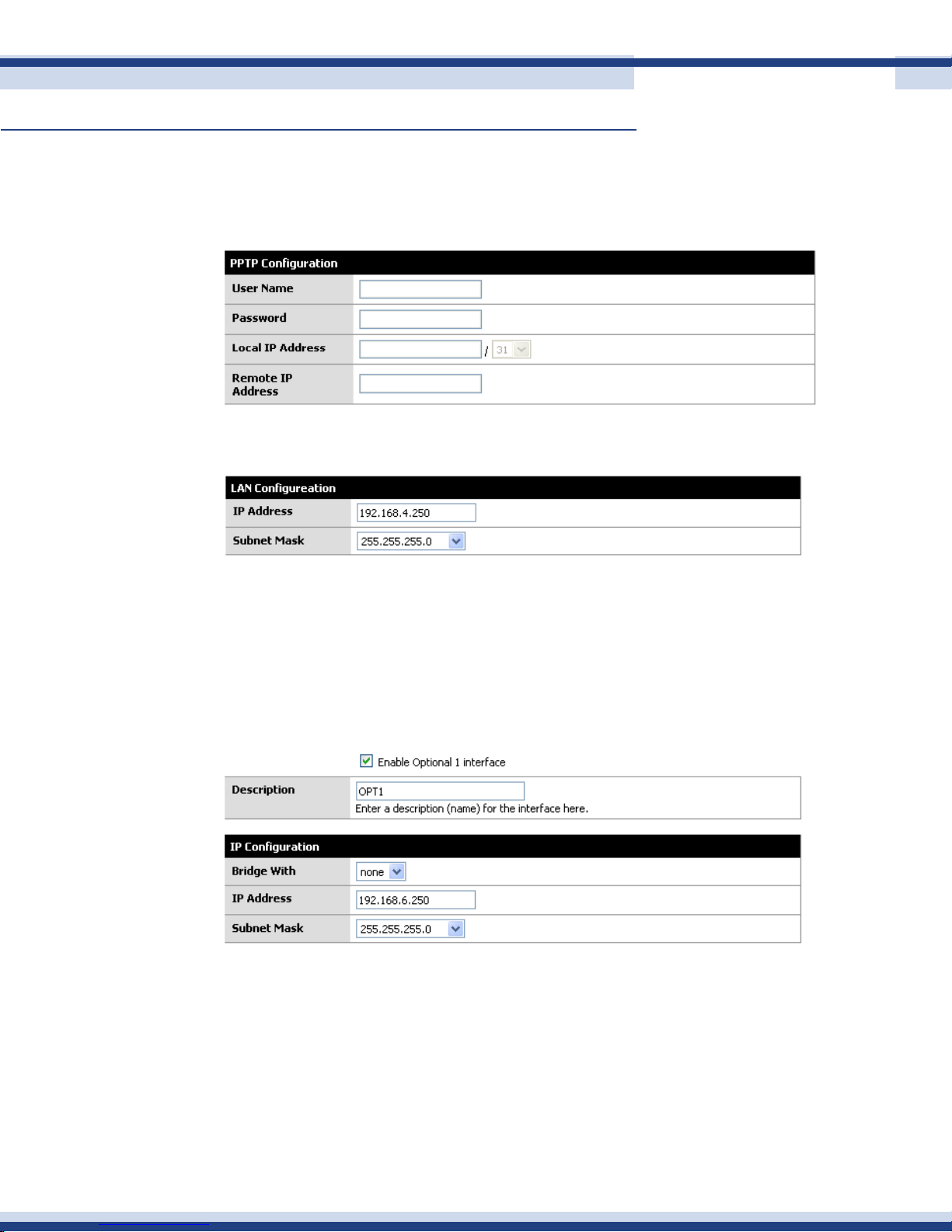
ppTp
PPTP is a service used in Europe only. If you are using a PPTP connection, check with your ISP
for the necessary setup information.
loCal area network
49
This is the Cortexa 7202 IP address and Subnet Mask as seen on the internal LAN. The
default is 192.168.10.1 for IP address and 255.255.255.0 for Subnet Mask.
oPt1
This option will only appear on the Interfaces menu if a network card is added to the
Cortexa
The OPT 1 is used for the video server data
The OPT 1 port is like having two separate internal networks
Bridge with: Select the interface that you would like to bridge with. If an interface is
selected, then the IP address and Subnet Mask will be the same as the bridged interface.
Version 2.2
Page 50
Cortexa 7202 ConfiGuration utility
Continued
If you opt not to bridge with another interface, you will need to setup an IP address and
Subnet Mask for the new local area network.
You may also change the description of the interface to make it easier to identify when
setting up rules and forwards.
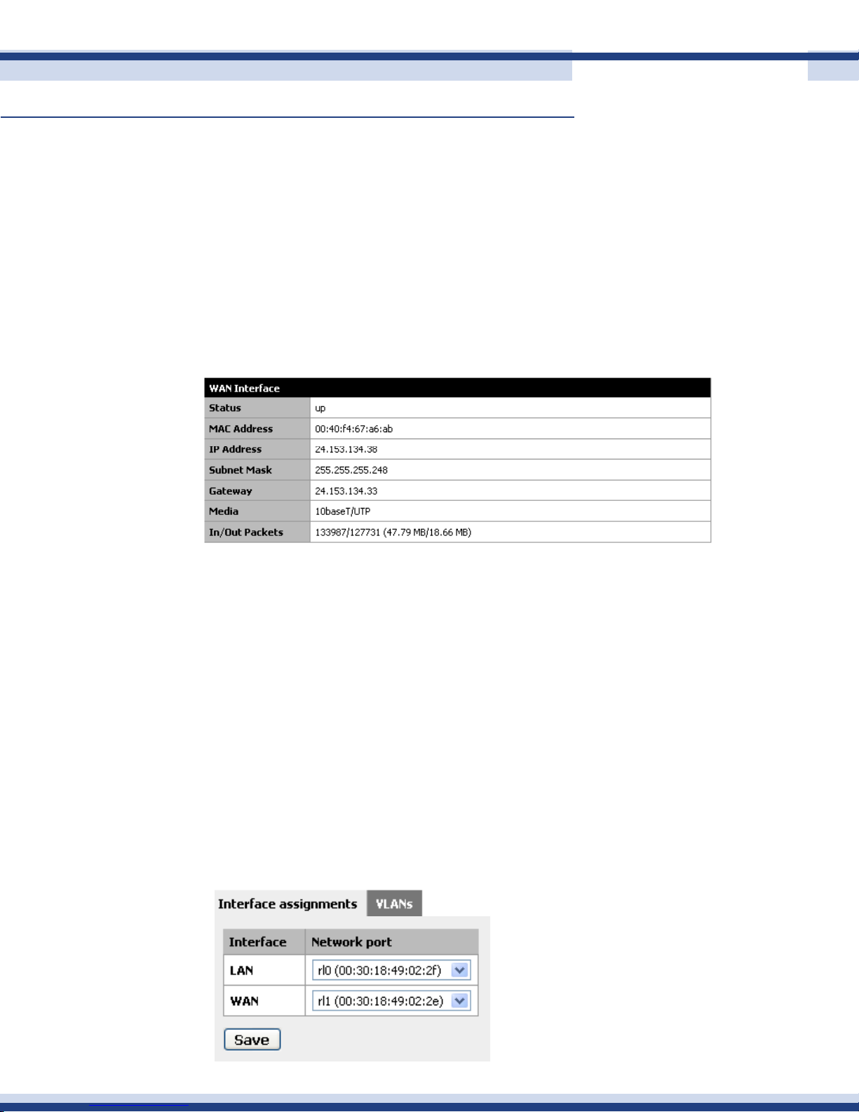
network status
The Status page displays the Cortexa 7202 current status. It reects the data and selections
entered using the setup pages.
50
network traffiC
This allows you to view real-time network trafc on all interfaces, WAN and LAN. In order
to utilize this function, install the plug-in as directed. If using Mozilla Firefox, the following
step also needs to be performed.
Copy NPSVG6.dll and NPSVG6.zip to your browser’s plug-ins folder. These les are normally
located in C:\Program Files\Common Files\Adobe\SVG Viewer 6.0\Plugins\
interfaCe assignments
This allows you to assign network ports to an Interface. You may also assign Virtual
networks.
Version 2.2
Page 51
Cortexa 7202 ConfiGuration utility
Continued
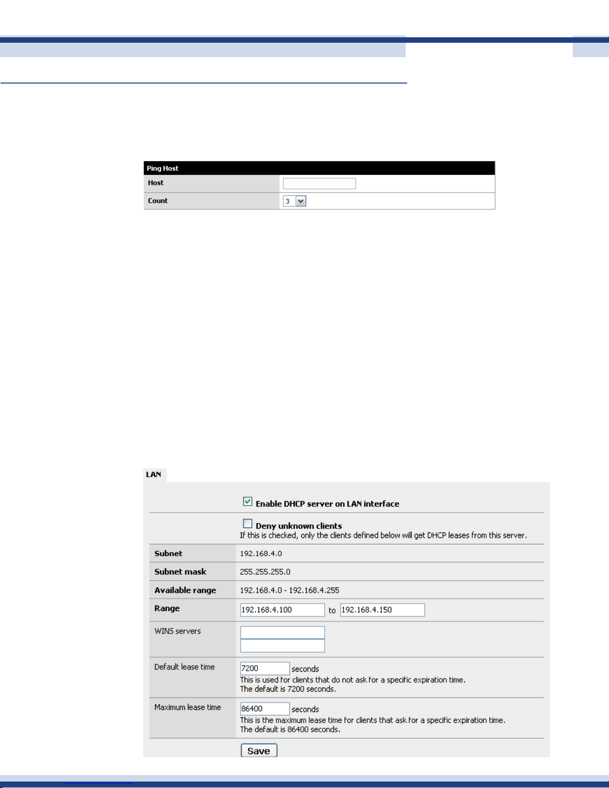
Ping host
Ping is a trouble-shooting tool to see if you can ping other systems connected to the
Cortexa.
n serviCes
dhCP server
The Cortexa can be congured as a DHCP Server from the DHCP Screen. The Dynamic
Host Conguration Protocol (DHCP) – A protocol that lets network administrators centrally
manage and automate the assignment of Internet Protocol (IP) addresses in an organization’s
network using the Internet’s set of protocol (TCP/IP). Each machine that connects to the
Internet needs a unique IP address.
51
When an organization sets up its computer users with a connection, the IP address must be
entered manually at each computer and, if computers move to another location in another
part of the network, a new IP address must be entered. DHCP lets a network administrator
supervise and distribute IP addresses from a central point and automatically sends a new IP
address when a computer is plugged into a different place in the network.
Version 2.2
Page 52

Cortexa 7202 ConfiGuration utility
Continued
Enabling the DHCP Server
To enable the DHCP server on a particular interface, click on the appropriate tab for the
interface and check the “Enable DHCP server on interface” box.
Deny Unknown Clients
With this option selected, the DHCP server will issue IP addresses to known MAC
addresses.
Range
In the rst box, enter the starting address of your DHCP range. In the second box, enter
the ending address of the range. Note that you do not want to make this the same as the
available range, as this includes the subnet address and broadcast address, which are
unusable. Also, the address of the Cortexa interface cannot be in the range.
52
WINS Servers
If you use an NT 4 domain, or have pre-Windows 2000 clients that need to access an Active
Directory domain, you will need to ll in your WINS server IP addresses in these boxes. If
you only have one WINS server, leave the second box blank.
Default and Maximum Lease Time
The default lease time is the length of the DHCP lease on any clients that do not request a
specic expiration time on their DHCP lease. The default is 7200 seconds, or two hours. For
the vast majority of network environments, this is too low. We recommend setting this to one
week; 604,800 seconds.
The maximum lease time must be more than the default lease time. Most networks will not
use this value at all. In most instances, you can set this to one second longer than the default
lease time.
Click Save to save your changes, then Apply to enable the DHCP server.
Version 2.2
Page 53
Cortexa 7202 ConfiGuration utility
Continued
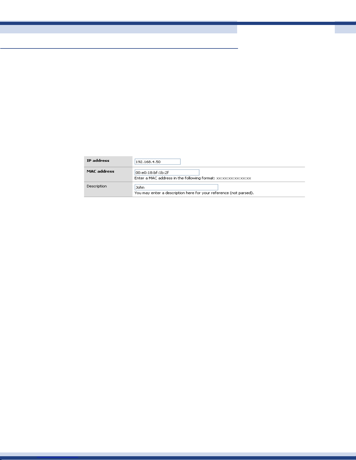
sTaTiC dhCp mappiNg
Static DHCP mappings can be used to assign the same IP address every time to a particular
host. This can be helpful if you dene access rules on the rewall or on other hosts on your
LAN based on IP address, but still want to use DHCP. Alternatively, you can keep the IP
address box blank to assign an IP out of the available range, when you are using the “Deny
unknown clients” option.
Click the + icon at the bottom of the DHCP conguration page to add a static DHCP
mapping.
53
In the MAC address box, ll in the system’s MAC address in the format xx:xx:xx:xx:xx:xx.
For Windows NT/2000/XP clients, you can get determine the MAC address by opening up
a command prompt and typing ‘ipcong’. For Windows 95/98/ME clients, go to Start, Run,
winipcfg. For Unix clients, use ifcong. In the IP address box, ll in the IP address you want
to be assigned to the client, or leave it blank to automatically assign one from the available
DHCP range. If you enter a static IP address, it must not be within the range of the DHCP
server.
It is recommended you ll in a description in the Description box to remind you what this
entry is for, though this is optional.
Click Save when you are nished and the mapping will be added.
Version 2.2
Page 54
Cortexa 7202 ConfiGuration utility
Continued
dns override
DNS – The Domain Name System (DNS) is the method by which Internet domain names are
located and translated into Internet Protocol (IP) addresses. A domain name is a meaningful
and easy-to-remember name for an Internet Address.
If there are certain DNS host names you want to override for your internal DNS clients, add
them under DNS overrides on this page. For example, if you want www.yourcompany.com to
point to a different site internally than it does from the Internet, enter an override for www.
yourcompany.com with the appropriate IP address.
This can also be used as a rudimentary, and easy to bypass, lter on web sites LAN clients
can visit by assigning the undesired host name to an invalid IP address. For example, to
block www.example.com, put in an override to redirect it to an invalid IP address, such as
1.2.3.4. Note that using a different DNS server or editing the hosts le on the client machine
54
gets around this restriction, but doing this is sufcient to block the site for the vast majority
of users.
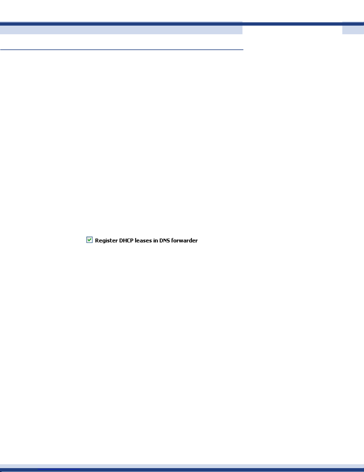
If your Cortexa acts as the DHCP server for your LAN, and you need name resolution
between hosts on the LAN, check the “Register DHCP leases in DNS forwarder” box. This will
append the default domain in Interfaces: General Setup. For example, if your PC name is
my-pc and your default domain is example.com, it will register my-pc.example.com with the
IP address assigned from DHCP, so the other hosts on your LAN can locate your machine by
that name.
Version 2.2
Page 55
Cortexa 7202 ConfiGuration utility
Continued
addiNg dNs overrides
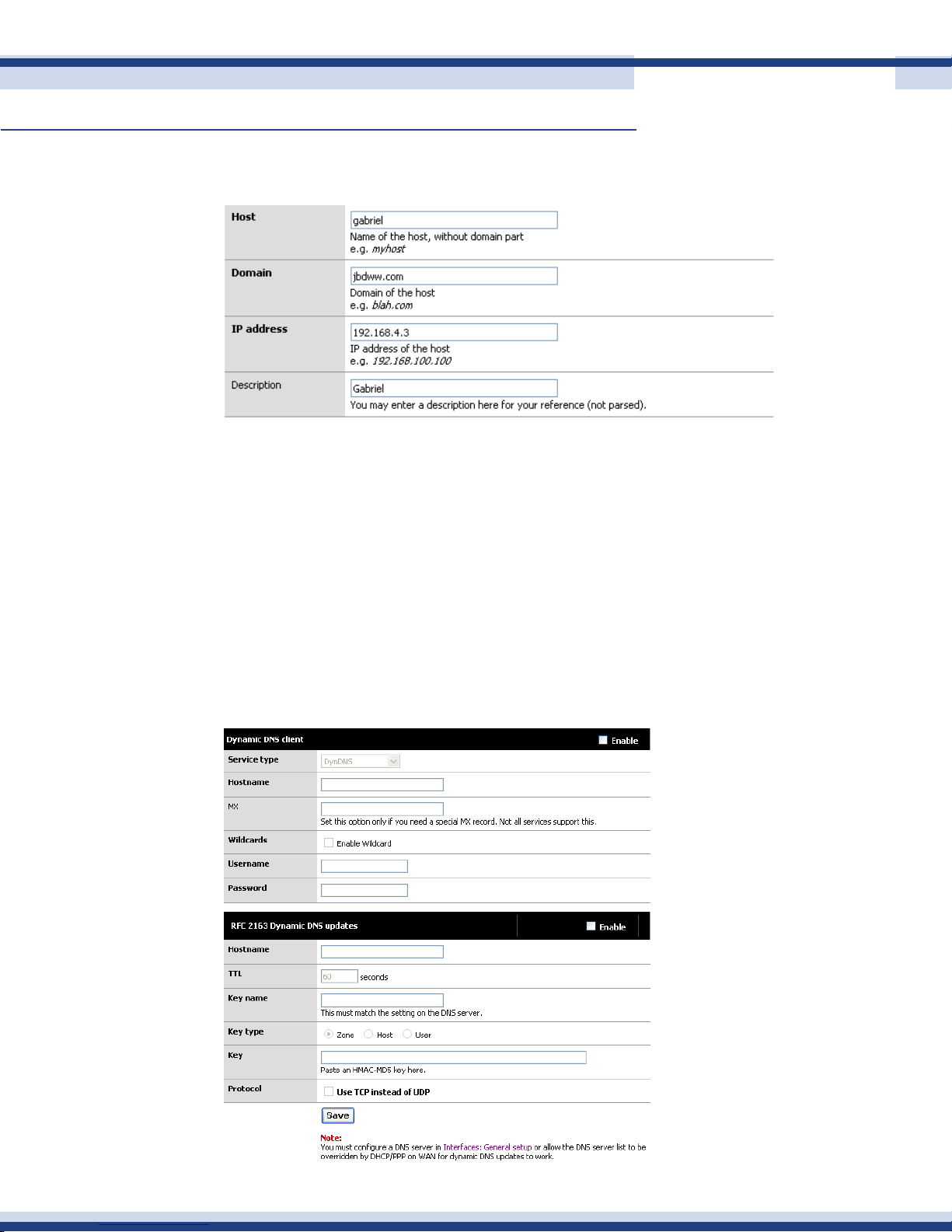
The Edit Screen allows the ability to add and change your current rules.
• Host: The host name on the domain without the domain part.
• Domain: The domain name of the host.
55
• IP: The new assigned IP address.
• Description: Gives the override a name for easy identication.
dynamiC dns
This screen allows you to congure Dynamic DNS. Dynamic DNS gives you the ability to nd
your Network over the Internet even though you do not have a static IP.
Version 2.2
Page 56

Cortexa 7202 ConfiGuration utility
Continued
CoNfiguriNg The dyNamiC dNs ClieNT
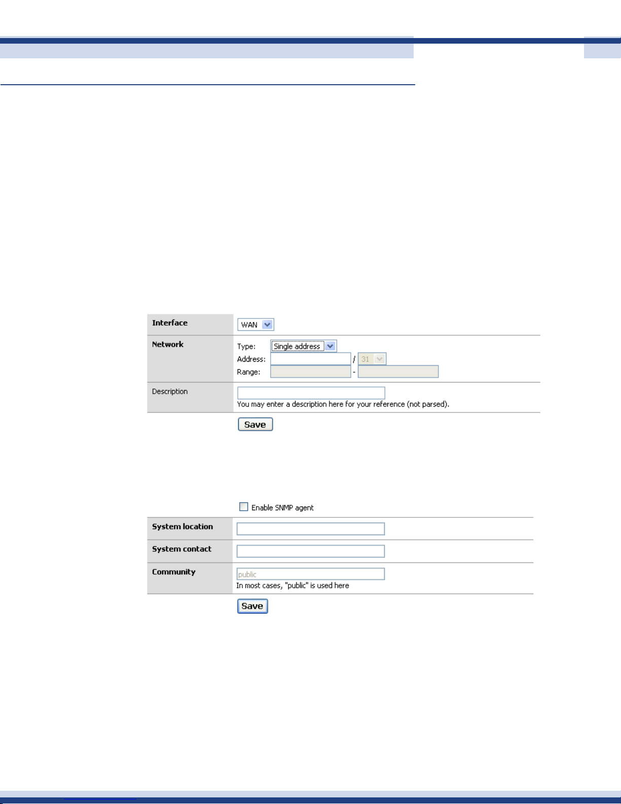
To start, rst check the “Enable Dynamic DNS client” box at the top of the page.
In the “Service type” drop down box, select the service you are using.
Some services support MX DNS records on dynamic DNS sub-domains. This helps ensure you
can get email to your host name. If your service supports this (dyndns.org is one that does,
others do as well), ll in your mail server’s host name in that eld. If you do not need an MX
record, or if your provider does not support them, just leave the eld blank.
Wildcards - If you want to enable wildcard on your dynamic DNS host name, check this
box. This means all host names not specically congured are redirected to your dynamic
DNS name. So if your dynamic DNS is example.homeip.net, and you enable wildcards,
www.example.homeip.net, mail.example.homeip.net, anything.example.homeip.net, etc. (i.e.
56
*.example.homeip.net) will all resolve to example.homeip.net.
The next two boxes are for your username and password. Enter your account information
from the Dynamic DNS provider.
Click Save. Your dynamic DNS host name should immediately be updated with your WAN IP
address. To verify this, ping your dynamic DNS host name. It should resolve to the IP address
of the WAN interface of your Cortexa. If not, check Diagnostics: System Logs for information
on why it failed.
Proxy arP
Proxy ARP means that a particular system, such as a rewall, will respond to ARP requests
for hosts other than itself. This can be used to make a rewall mostly disappear from the
systems on a network.
For example, if you had a /28 subnet from your ISP that is routed through the Cortexa
router, your router appears at the IP of x.x.x.97 with a network address of x.x.x.96 and
a broadcast address of x.x.x.111. This leaves a usable chunk of 14 addresses for your
hosts.
Version 2.2
Page 57
Cortexa 7202 ConfiGuration utility
Continued
If you wanted to rewall these hosts from the Internet without using Proxy ARP, you would
need to subnet your addresses and therefore lose two more addresses for the new network
and broadcast, plus half of your remaining IP’s would be in the non-rewalled half.
Another method would be to have the rewall do port forwarding between all of the
addresses to non-routed IP’s (192.168.x.x) for your servers. Done properly, this would be
work. It isn’t as transparent and may break some protocols like active FTP.
By using Proxy ARP, you can set up your systems in a DMZ to separate them from your client
systems. This is also the least invasive method to set up, since you can keep the same IP’s on
all of the servers as you had when things were not rewalled.
57
snmP
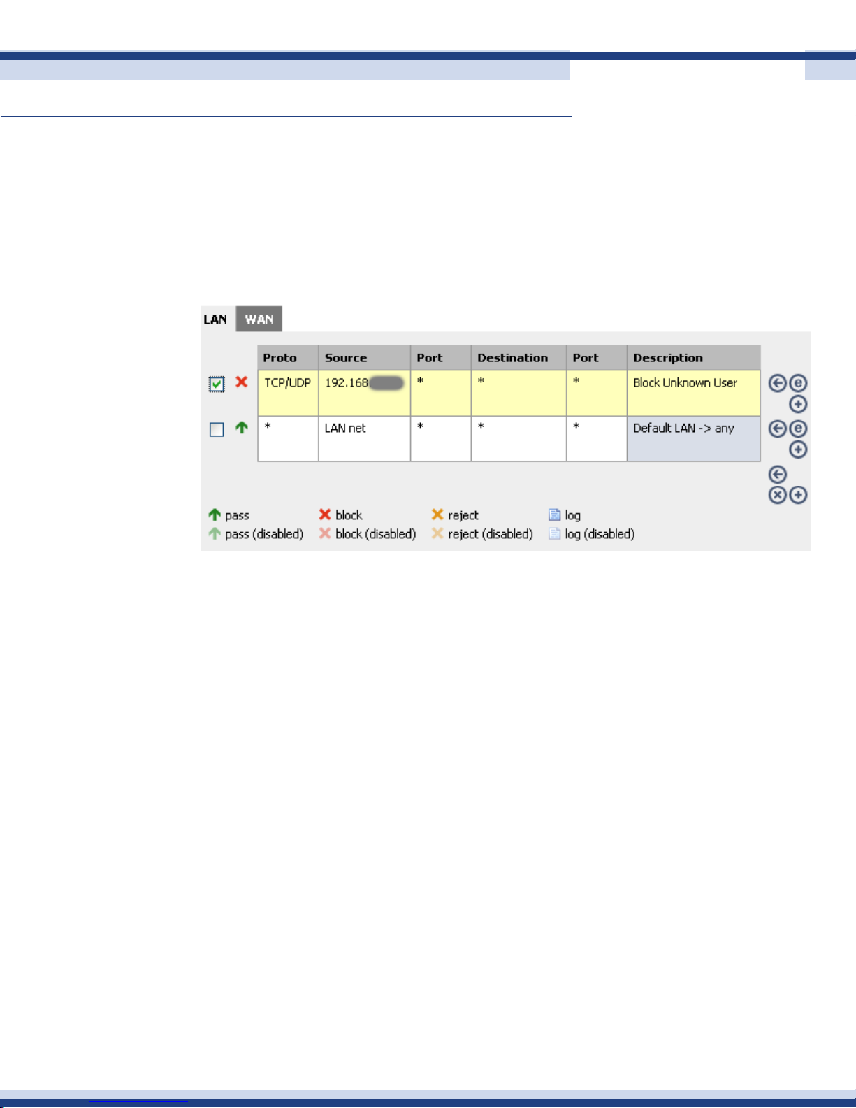
You can enable SNMP on your LAN interface on this screen. This is useful if you have a
network management or monitoring system that takes advantage of it.
The System location and System contact boxes can be left blank, but can assist you in
determining which device you are monitoring if you have several monitored hosts.
The Community is generally set to public, but if you are concerned about security, you should
set this to something difcult to guess, containing numbers and letters. This community name
is still passed over the network in clear text, so it could be intercepted, though the most
anyone could get with that community name is information on the setup and utilization of
your rewall. In most environments, this is likely to be of little to no concern, but is something
to keep in mind.
Version 2.2
Page 58
Cortexa 7202 ConfiGuration utility
Continued
After setting the values as you desire, click Save and your changes will be applied.
n firewall
rules
Rules allow the ability to control the data processed through the Cortexa 7202. This control
gives you the option to limit Internet access for specic systems on your network.
58
The table shows the following.
• Proto: The protocol that is being analyzed
• Source: The source of the trafc that is to be analyzed
• Port: The port that is being analyzed
• Destination: The destinations that the source is allowed to go to
• Port: The ports that the source is allowed to connect to
• Description: An easy way to identify the rule
Rules may be prioritized with the arrows, and are evaluated on a rst-match basis (i.e. the
action of the rst rule to match a packet will be executed). This means that if you use block
rules, you will have to pay careful attention to the rule order. Everything that is not explicitly
passed is blocked by default.
Version 2.2
Page 59
Cortexa 7202 ConfiGuration utility
Continued
59
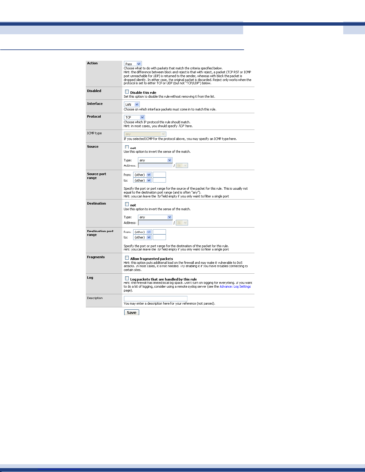
The Edit screen allows the ability to add and change your current rules:
• Action: Determines if the rule is a Passing or a Blocking rule.
• Disable: Allows you to disable the rule so you can save the settings for a later time.
• Interface: The interface that the packets must come in to match this rule.
• Protocol: The IP protocol that the packets must match for this rule.
• Source: Packet source.
• Source Port Range: The port that the packet is on and must match for this rule.
• Destination: Destination address the packets are trying to reach and if matched,
will be denied.
• Destination Port Range: The range of ports that are allowed for this rule.
• Fragments: Allows fractional packets to pass through.
• Description: Gives the rule a name to help nd it.
Version 2.2
Page 60
Cortexa 7202 ConfiGuration utility
Continued
forwards
iNBouNd forWards
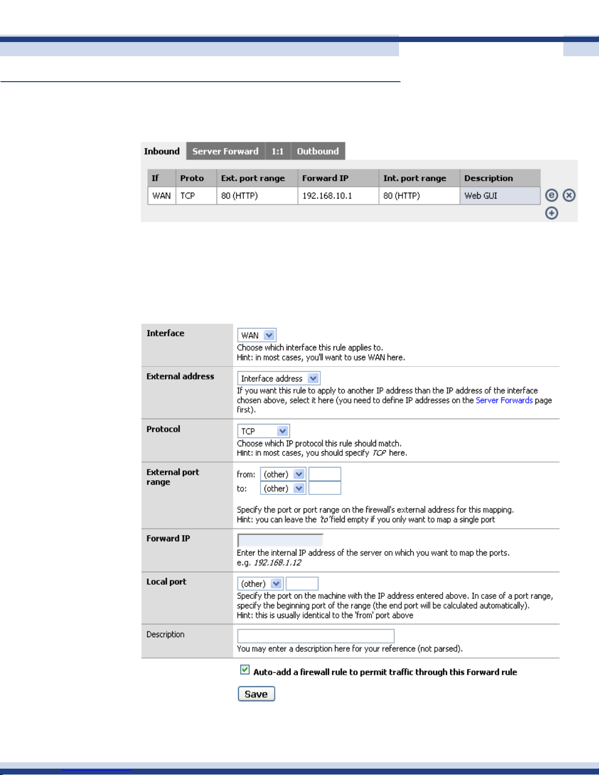
Forwards Rules allow you to set up public services on your network, such as web servers,
ftp servers, or e-mail servers. When users send this type of request to the network via the
Internet, the Cortexa 7202 will forward those requests to the appropriate PC.
addiNg iNBouNd forWards
60
Version 2.2
Page 61

Cortexa 7202 ConfiGuration utility
Continued
Interface
Interface is generally set to WAN in order to permit trafc coming from the Internet. You can
also select any optional interfaces here.
Optional interfaces might be useful on a DMZ interface to allow access from the DMZ to a
port on a host on your LAN. For example, if you want to use a LAN DNS server, you could
put an Inbound NAT rule in on the DMZ interface opening UDP port 72 to your DNS server’s
LAN IP address, and use Cortexa’s DMZ interface IP address as your DNS server on DMZ
hosts. There is no real advantage doing this versus putting in a rewall rule to permit this
trafc, and using the LAN IP address of the DNS server.
External address
External address is set to the WAN interface IP address. If you have multiple public IP’s, you
can use other addresses here that you have previously dened on the Server NAT tab.
61
Protocol
Choose which IP protocol the service you are using requires, TCP, UDP or TCP and UDP.
External port range
Either select the desired protocol from the drop down box, or type in the port range in the
text boxes. You can leave the “to” eld empty if you only want to map a single port.
Forward IP
This is the internal IP address of the machine to which you are mapping the ports. In the
given example, the LAN IP address of the web server is 192.168.10.4. This can also be a
host on an optional network, and ideally it will be to a host on a DMZ. You should avoid
opening ports to your LAN if possible.
Local port
This is the port on the Forward IP dened above to which we want to translate the connection.
In this case it is the same as the external port, but it doesn’t have to be.
Description
Optional, however we strongly recommend putting in a description so you remember the
purpose of this entry, and to make your rules easier to read and comprehend.
Version 2.2
Page 62
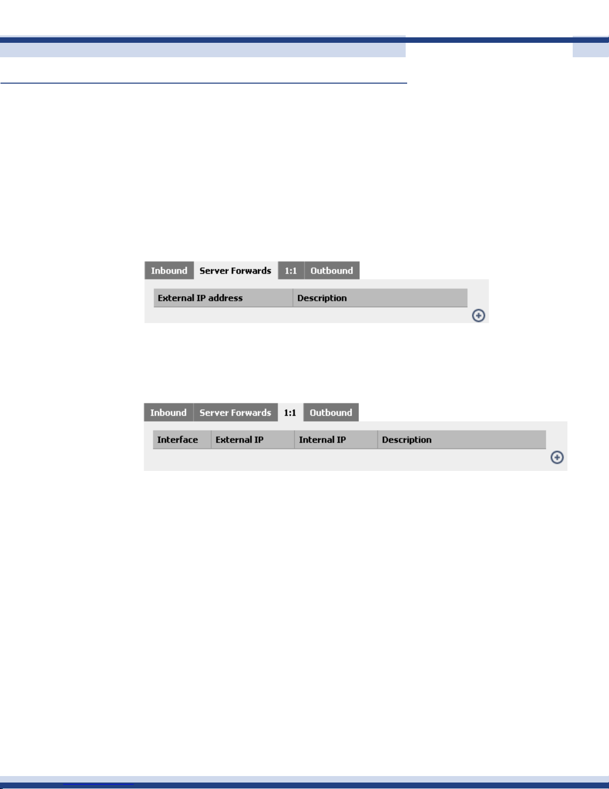
Cortexa 7202 ConfiGuration utility
Continued
Auto-add a rewall rule to permit trafc through this Forward rule
We recommend you check this box in all circumstances. If you need to tighten the default
rule, you can do so later. If you don’t let the webGUI create the rule automatically, it’s more
likely to be incorrect or problematic.
Click Save, then Apply Changes. You will then see the result, similar to the following.
server forWards
If you want to use a public IP address other than the WAN interface address with Inbound
62
Forwards, you need to dene the address in Server Forwards rst.
1:1 forWard
1:1 Forward maps an internal IP to external IP, generally mapping a public IP address to
a private IP address and vice versa. When you assign a 1:1 Forward mapping, any trafc
coming from that host to the Internet will be NAT’ed to the dened external IP, and any
trafc coming into the external IP will be NAT’ed and passed to the internal IP if rewall
rules permit. (by default, the rewall rules do not allow any inbound trafc to 1:1 Forward
mappings). You can also map entire subnets with one entry.
Version 2.2
Page 63
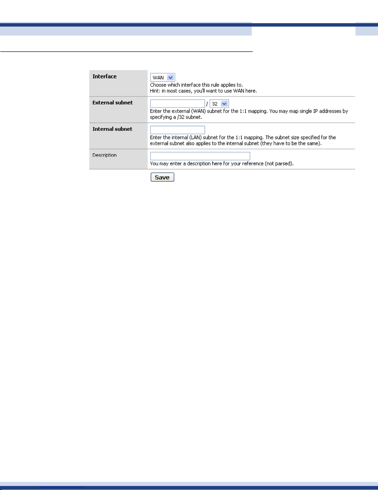
Cortexa 7202 ConfiGuration utility
Continued
addiNg 1:1 forWards
Interface
Interface will be WAN in most cases.
63
External IP
The external IP will be set to the IP address you wish to map.
Internal subnet
In most cases this will be a single IP address on either your LAN or an optional interface like
a DMZ.
Description
Description is optional but recommended. After verifying your entries, click Save and Apply
Changes.
aliases
Aliases act as placeholders for real IP addresses and can be used to minimize the number of
changes that have to be made if a host or network address changes. You can enter the name
of an alias instead of an IP address in all address elds that have a blue background. The
alias will be resolved to its current address according to the list below. If an alias cannot be
resolved, e.g. because it has been deleted, the corresponding element will be considered
invalid and skipped.
statiC route
Paths through the network must be found and made available to the router so it knows the
best path on which to forward a packet to its destination. Static routing is the process a
network administrator uses to manually congure network routes.
Version 2.2
Page 64
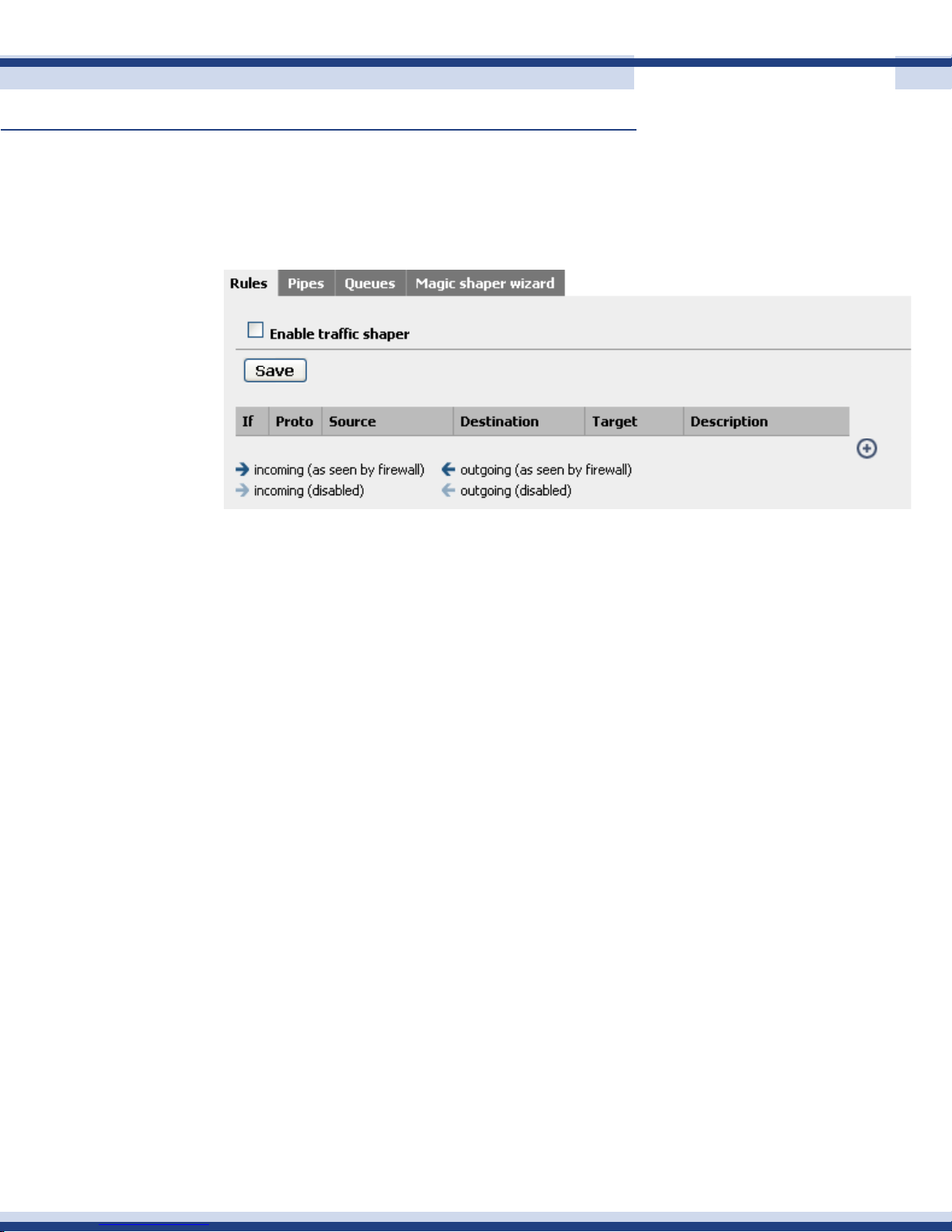
Cortexa 7202 ConfiGuration utility
Continued
traffiC shaPer
Trafc shaping gives you the ability to allow a specic amount of bandwidth for each device
on the LAN.
Current Rules:
64
• If: The interface packets must go through
• Proto: The protocol being analyzed
• Source: The source of the trafc to be analyzed
• Port: The port being analyzed
• Destination: The destination being analyzed
• Port: The destination port being analyzed
• Bandwidth: The amount of bandwidth allowed for this rule
• Delay: The amount of delay before packets are allowed through
• Mask: Dynamic rule with the bandwidth given above
• Description: An easy way to identify the rule
Version 2.2
Page 65
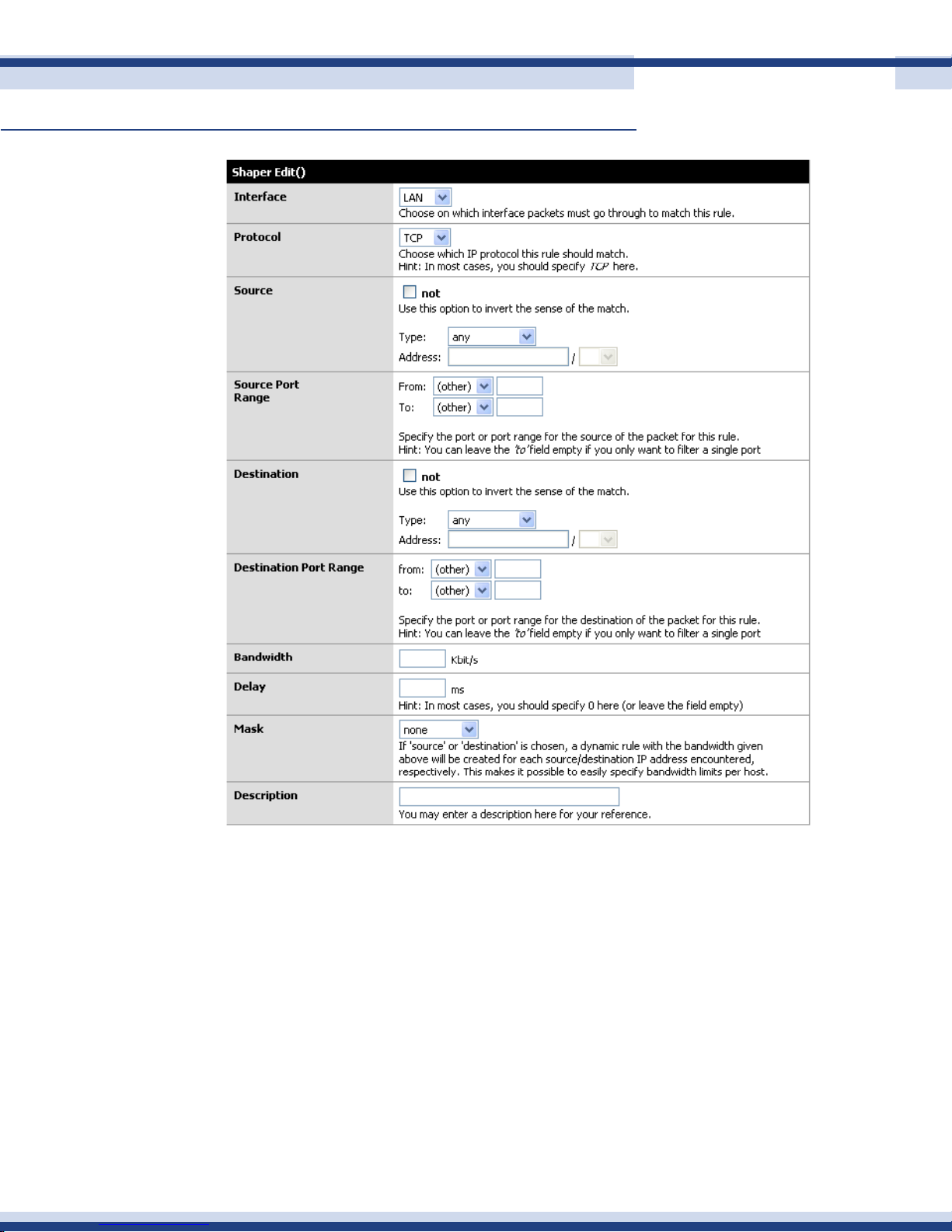
Cortexa 7202 ConfiGuration utility
Continued
65
The Edit screen allows the ability to add and change current Rules:
• Interface: The interface packets must match
• Protocol: The IP protocol packets must match
• Source: The source of the packets must match. You may use the “not” function so
everything else will match, but not the source
• Source Port Range: The port the packet is on must match
• Destination: The destination address that the packets are trying to reach and, if
matched, the packets will be shaped
• Destination Port Range: If the ports are matched, the packets will be shaped
• Bandwidth: The amount of bandwidth that is allowed
• Delay: Holds the packets for a specic amount of time. In most cases it is 0 or
blank
Version 2.2
Page 66
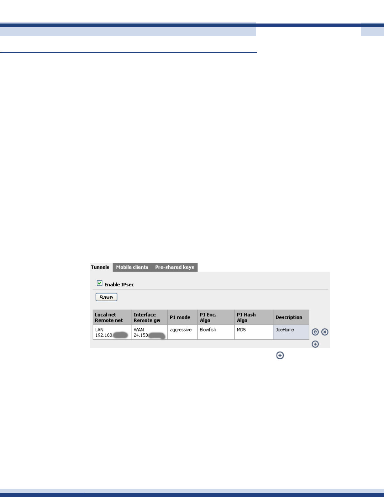
Cortexa 7202 ConfiGuration utility
Continued
• Mask: If ‘source’ or ‘destination’ is chosen, a dynamic rule with the bandwidth
given above will be created for each source/destination IP address encountered
respectively, which makes it possible to easily specify bandwidth limits per host
• Description: Gives the rule a name to make them easier to locate
n vPn (virtual Private network)
Virtual Private Networking (VPN) is a security measure that basically creates a secure
connection between two remote locations. The connection is very specic as far as its settings
are concerned; and creates the security. The VPN screen allows you to congure your VPN
setting to make your network more secure.
iPseC
This is used if you decide to build an IPSEC tunnel between your rewall and some other
network. The most common uses we see are connecting home networks to the ofce, or
66
setting up private WANs.
There is only one section of the Cortexa interface that you need to use to do this.
Now we need to add a VPN connection, to do this click on the icon.
The rst area is the one you use to establish what network ranges will use this IPSEC tunnel.
Version 2.2
Page 67
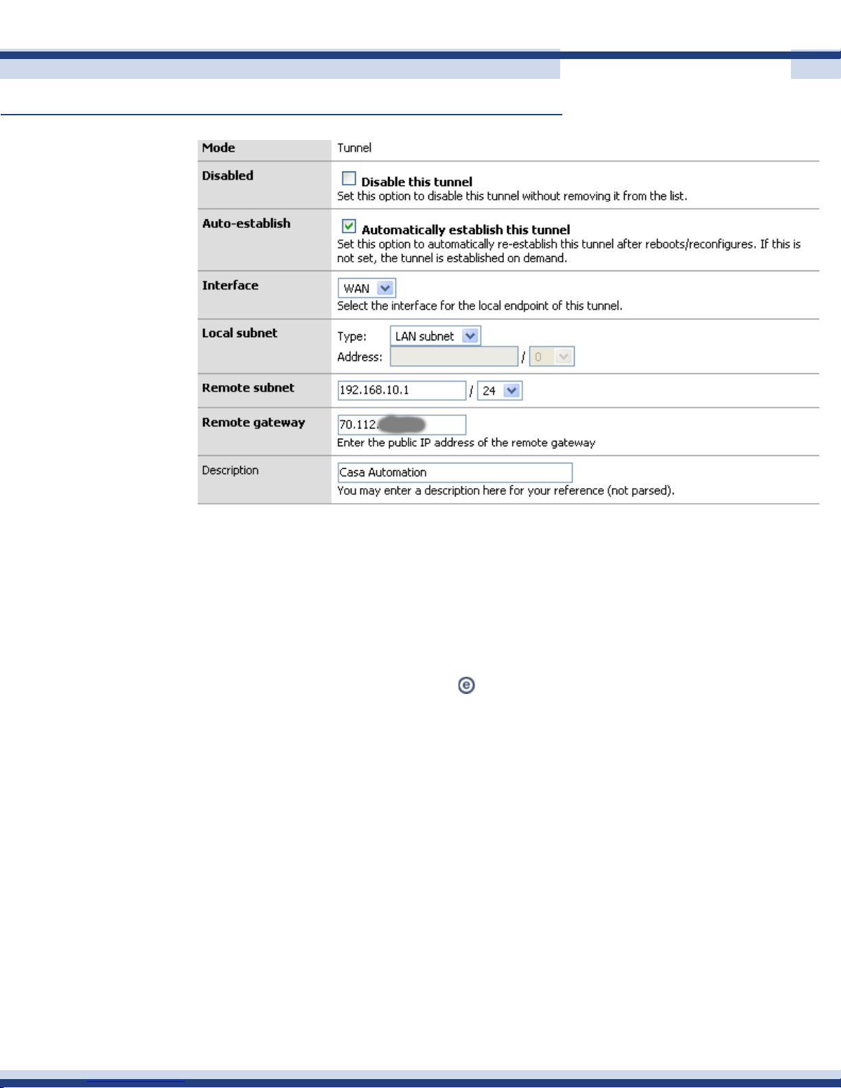
Cortexa 7202 ConfiGuration utility
Continued
67
This is the rst set of elds that we need to concentrate on. Later, when testing your tunnel,
you can actually fail to establish level 2 connection if this data is incorrect. We will note what
to pay particular attention to as we go along.
Mode: This cannot be changed.
1.
Disabled: This is an “on / off” button if you need to disable the tunnel for whatever
2.
reason. Simply select the edit or from the main VPN: IPsec window and click this
checkbox element, then select Apply at the bottom of the page. When you need
the tunnel again, reverse the process.
Interface: This is how you determine which part of your network will be the
3.
termination point end point for the VPN Tunnel. If you are connecting to a remote
server, then WAN is your option.
Local subnet. This is where you can set which parts, hosts, or the entire LAN, can
4.
be accessed from the other side of the VPN tunnel. The easiest thing to do is to set
the LAN subnet as the option; this means your entire LAN will be accessible from
the remote network. IMPORTANT: The other end of the tunnel has this same eld.
Make sure the other end is set exactly as you set this end. For example, if you
selected “Single host” in this section and entered the IP address of that host, the
other person would set that host in their “Remote Subnet” eld.
Version 2.2
Page 68
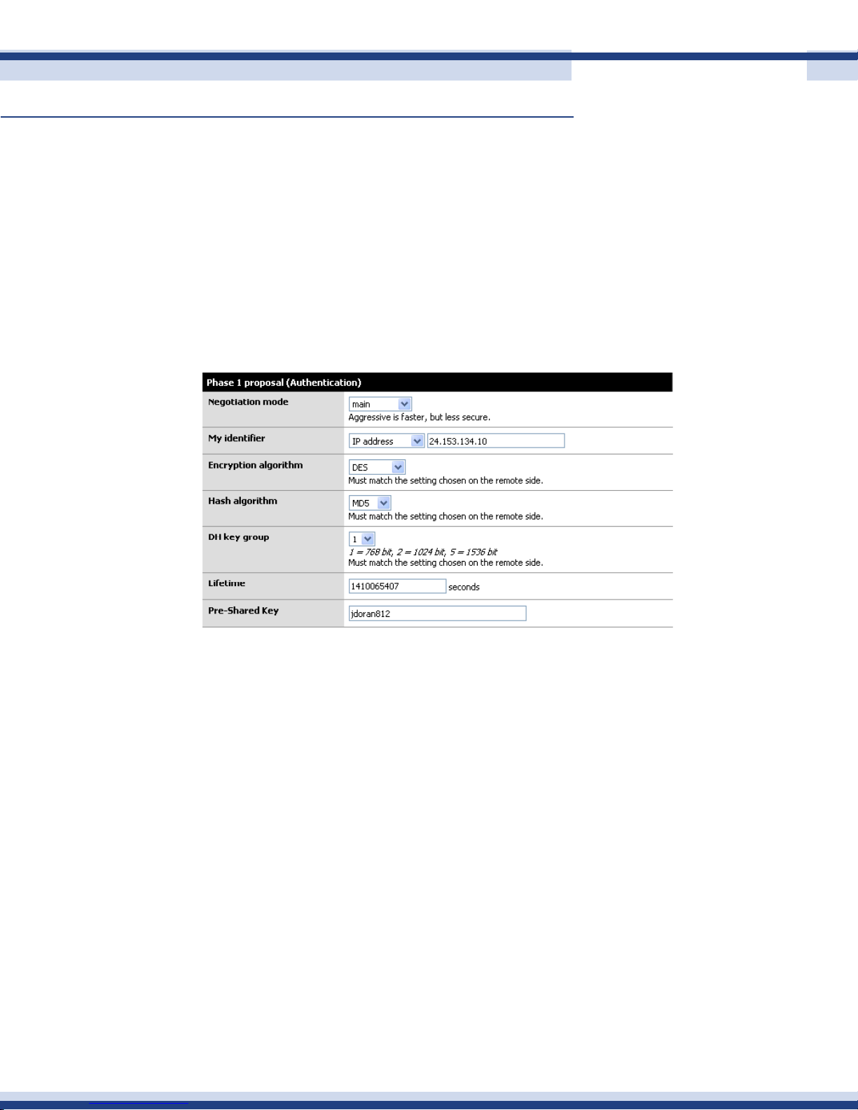
Cortexa 7202 ConfiGuration utility
Continued
Remote Subnet. This is more than just labeling which host(s) you want to access on
5.
the other network. As mentioned in item 4 it is paramount that you set this exactly
like the “local subnet” section. If not, level 2 of the VPN connection will fail and
trafc will not pass from one VPN segment to the other.
Description: We strongly encourage some documentation here.
6.
Now that the basics for the routing have been established. We can now move to phase 1 of
the VPN authentication process.
68
Here, and even in phase 2, it is vital to ensure both VPN servers have EXACTLY the same
settings for all of these elds.
Negotiation mode: This is the type of authentication security that will be used.
1.
Unless you are extremely concerned about security, leave this as aggressive. It is
signicantly faster and will ensure that your VPN tunnel will rebuild itself quickly
and probably won’t timeout an application if the tunnel was down when the
resource on the other end was requested.
My Identier: This is the key to probably 90% of problems where the VPN tunnel
2.
is not established. Very simply, set your identier to something that isn’t going to
change. So if you leave it as My IP address, then make sure that IP is static and
persistent. If you use a DHCP assigned address then we suggest using domain name
instead. This is because the domain name can be completely your own, even if you
do not own the domain name.
Version 2.2
Page 69
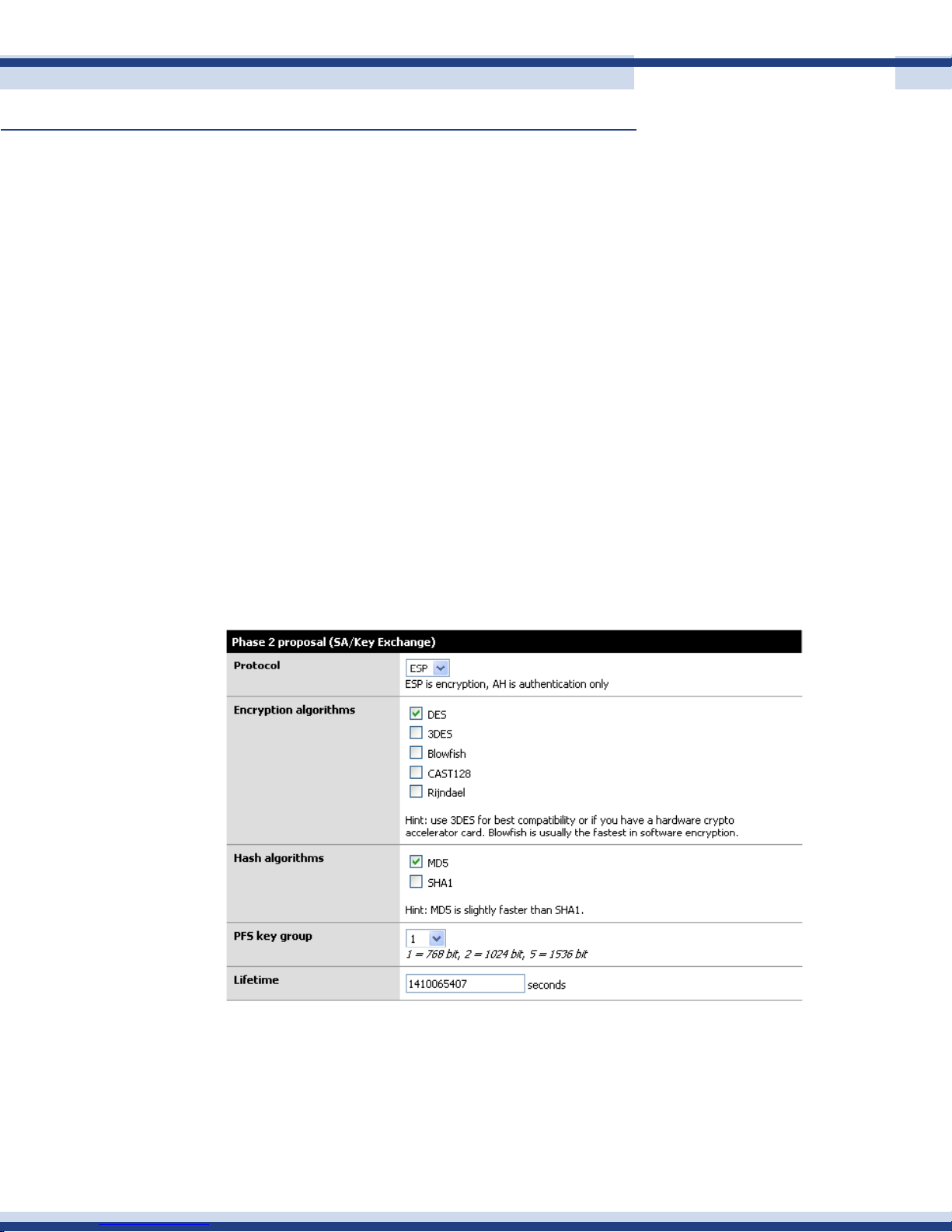
Cortexa 7202 ConfiGuration utility
Continued
Encryption Algorithm: 3DES is the de facto standard if you are connecting to
3.
another Cortexa, or a system that will support it, change this to Blowsh. It is more
secure and about twice as fast! If you are trying to connect to a VPN device that
only supports DES then you will need to downgrade and hope no one decrypts
your key exchange. MAKE SURE BOTH VPN DEVICES ARE USING THE SAME
ENCRYPTION ALGORITHM.
Hash Algorithm: this is the hash used for checksum. MD5 is a good choice, SHA1
4.
is another algorithm, but not everything supports it. Again make sure you are using
the same setting as the other end of the tunnel.
DH Key Group: Most systems will support at least up to 1024 bit. This is what we
5.
recommend using.
Lifetime: This eld is more important than it appears. This lifetime, as opposed to
6.
the one in phase 2, is how long your end will wait for phase 1 to be completed. We
suggest using 28,800 in this eld.
69
Pre-Shared Key: This key must be exactly the same on both VPN routers. It is case
7.
sensitive, and it does support special characters. We suggest using both.
Phase 2 is what builds the actual tunnel, sets the protocol to use, and sets the length of time
to keep the tunnel up when there is no trafc on it.
Version 2.2
Page 70
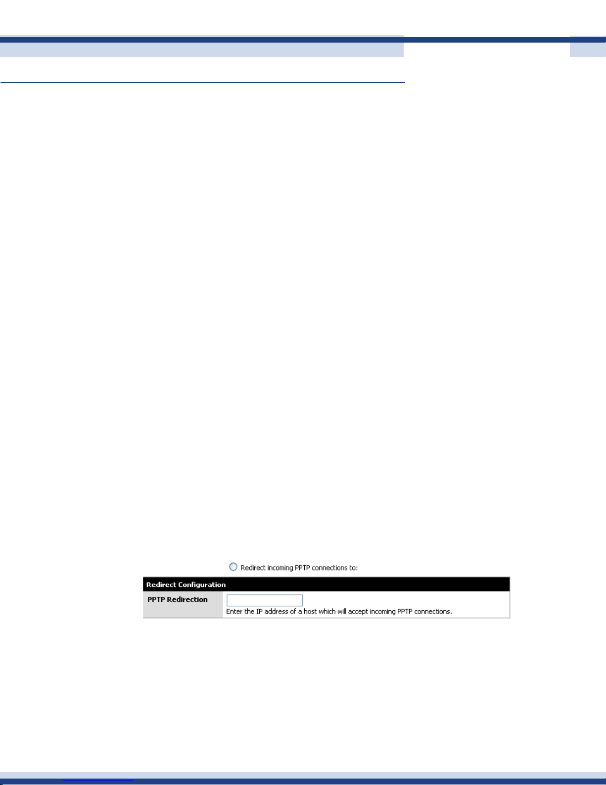
Cortexa 7202 ConfiGuration utility
Continued
Protocol: ESP is the de facto VPN transport protocol. We suggest leaving this as is.
1.
Note: The system should auto-generate a rewall rule for you to allow ESP or AH
to the endpoint of the VPN. We will check this later. If it does not, you will need to
make a rewall rule allowing ESP (or AH if you changed this) trafc to the interface
you established as your end point of the tunnel. We will outline that later.
Encryption algorithms: As before in phase 1, make sure you are setting the
2.
algorithm exactly as it is set on the other VPN server. You can use several, and
when you do so everything you select is available for use. We recommend keeping
things simple so only check the one you are going to use.
Hash algorithms: Just as in phase 1, make sure your selected hash matches
3.
on both ends. And as in step 2, don’t add things you don’t need. SHA1 is the
suggestion if you can, but MD5 is always a good alternative.
PFS key group: this works exactly like it does in phase 1. We suggest using 1024
4.
bit, the default is off.
70
Lifetime: This is the lifetime the negotiated keys will be valid for. Do not set this to
5.
too high. We suggest one day, 86,400. A value larger than this will be less secure.
PPtP
PPTP Point to Point Tunneling Protocol – A protocol that allows the Point to Point Protocol
(PPP) to be tunneled through an IP network. PPTP does not specify any changes to the PPP
protocol, but rather describes a “tunneling service” for carrying PPP (a tunneling service
is any network service enabled by tunneling protocols such as PP2P, L2F, L2TP , and IPSEC
tunnel mode). One example of a tunneling service is secure access from a remote small
ofce network to a headquarters corporate intranet via a Virtual Private Network (VPN)
that traverses the Internet. However, tunneling services are not restricted to corporate
environments and may also be used for personal (i.e., non-business) applications.
If you have your own internal PPTP server, you may redirect the PPTP request to your
internal PPTP server.
Version 2.2
Page 71
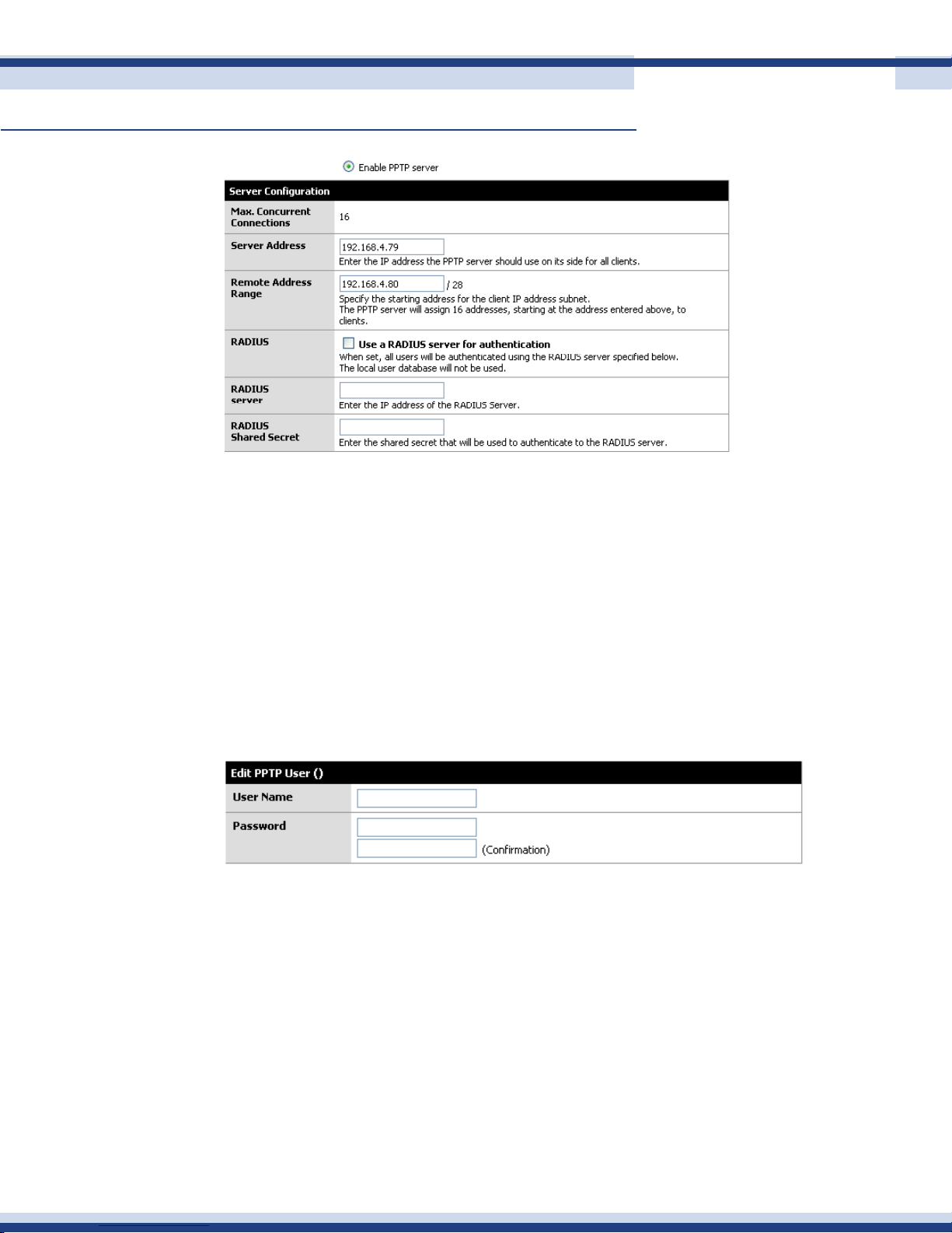
Cortexa 7202 ConfiGuration utility
Continued
• Max Connections: The maximum allowed tunnels at any time
• Server Address: The IP address that the PPTP server should use for all clients
71
• Remote Address Range: The range of IP addresses given to clients
• RADIUS: If you wish to use a RADUIS server to handle all users’ authentications
• RADIUS server: The IP address of the RADIUS Server
• RADIUS Shared Secret: The shared secret that the RADIUS server is using
PPtP users
Allows you to add PPTP users to gain access to the network through the PPTP tunnel.
Version 2.2
Page 72
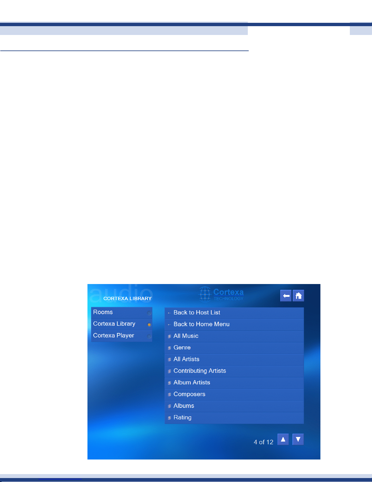
Cortexa audio player
n Cortexa library
The Cortexa Home controller has a built-in audio player, and also supports the Universal
Plug and Play (UPnP) protocol. This means that music may be streamed from any compatible
device or application and played using the audio out port on the Cortexa controller. We
have tested the Library and Player functionality with many hardware devices and software
applications and recommend using Windows Media Player 11 unless you have a preference
for an alternative platform.
The library that you are sharing from must be congured to share les with the Cortexa.
This is done within the application, e.g. WMP11. Multiple libraries on the same network
may be shared.
Having congured your music library to share, the Cortexa Library and Player functionality
72
is highly intuitive.
1. Click on Cortexa Library. This will display a list of “hosts” discovered by the
Cortexa.
2. Select a host and then click on Music or Playlist. Selecting Music will display the
screen below.
Version 2.2
Page 73
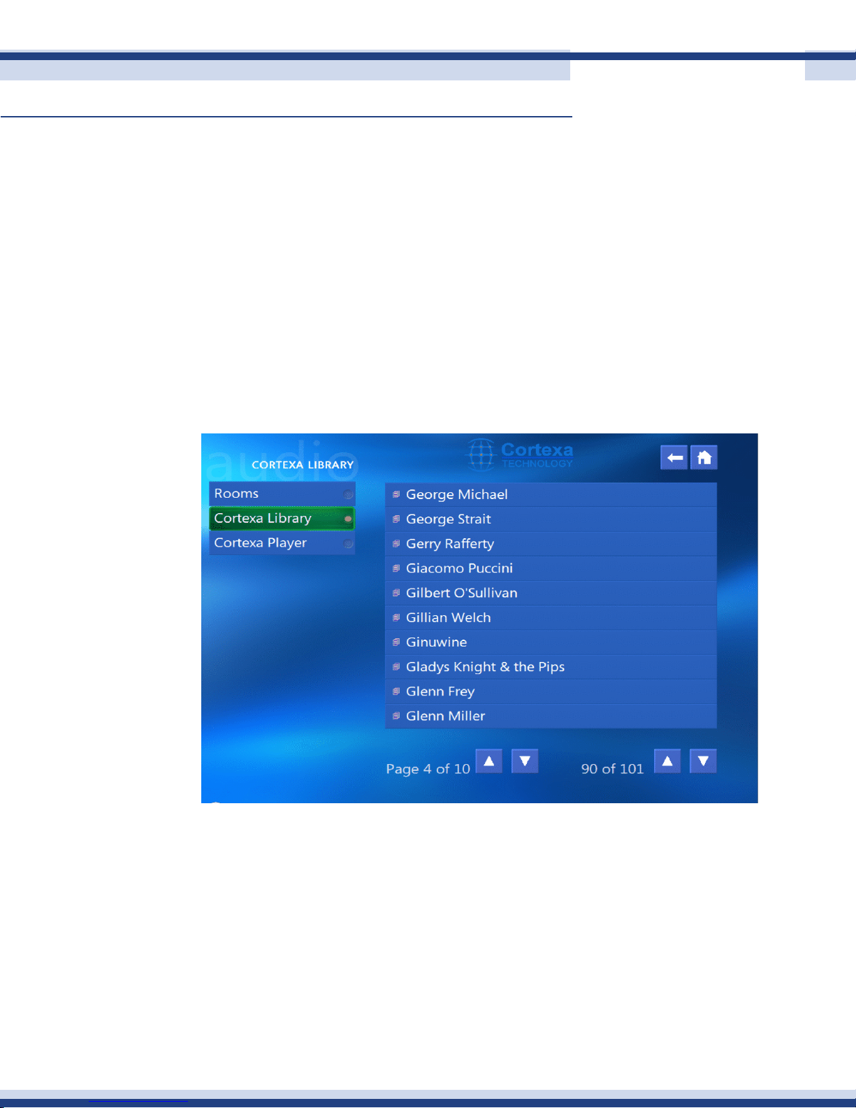
Cortexa audio player
Note: this screen may vary slightly depending on which application is being used, in our case
WMP11.
Selecting “All Artists” will list all artists found in the format below. For large lists, there are
two sets of scroll keys. The keys on the right scroll up and down individual pages, while the
keys on the left scroll up or down 100 entries.
There is a limit of 10,000 entries. For most libraries this will not be a factor, however with
large music libraries this could become an issue if All Songs is selected. In this case, the
library may still be accessed but must be listed using a parameter other than songs, e.g.
artist or genre.
73
Continued
3. Select the song or playlist to be played and click on it. You will see the bar highlight
when clicked, but no other indication that the song is playing.
Version 2.2
Page 74
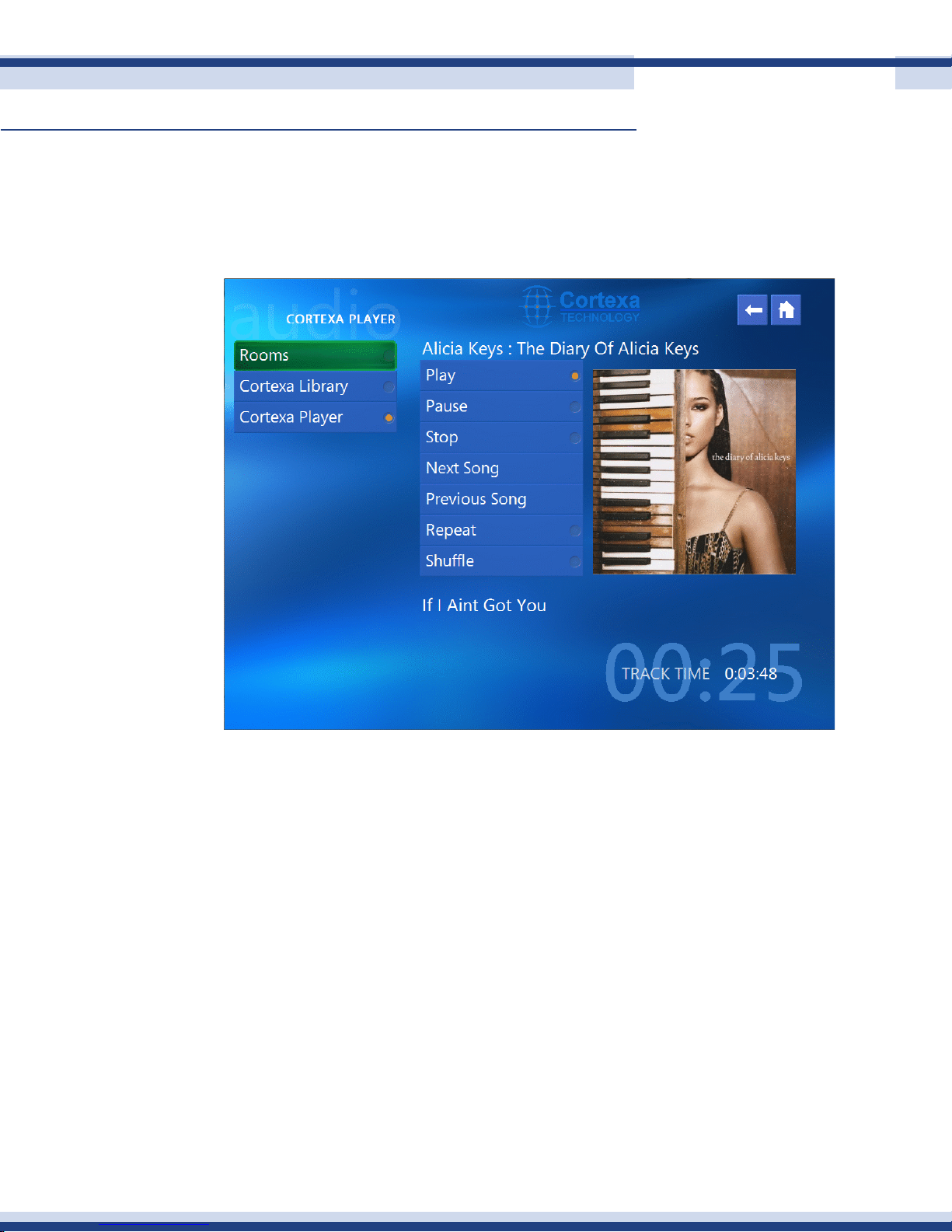
Cortexa audio player
n Cortexa Player
You can view and control the currently playing song or playlist by clicking on the Cortexa
Player.
74
Continued
The Player allows full control of songs and playlists with intuitive buttons in the center of the
screen. Also, if the song has associated cover art, this will be displayed in the panel to the
right of the control buttons.
Version 2.2
Page 75

appendix a
75
n Network troubleshootiNg
This appendix consists of frequently asked questions, and may provide possible solutions to
problems regarding the installation and operation of the Cortexa.
If you need further support, please contact us at [email protected].
I need to set a static IP address on a PC
The Cortexa, by default, assigns an IP address range of 192.168.10.100 to 192.168.10.150
using the DHCP server in the Cortexa. To set a static IP address, you can only use the ranges
192.168.10.2 to 192.168.10.99 and 192.168.10.151 to 192.168.10.254. Each PC or
network device that uses TCP/IP must have a unique address to identify itself in a network.
If the IP address is not unique to a network, Windows will generate an IP conict error
message. You can assign a static IP address to a PC by performing the following steps:
For Windows 95, 98, and Me:
A. Click Start, Settings, and Control Panel. Double-click Network.
B. In The following network components are installed box, select the TCP/IP-
>associated with your Ethernet adapter. If you only have one Ethernet adapter
installed, you will only see one TCP/IP line with no association to an Ethernet
adapter. Highlight it and click the Properties button.
C. In the TCP/IP properties window, select the IP address tab, and select Specify an
IP address. Enter a unique IP address that is not used by any other computer on
the network connected to the Router. You can only use an IP address in the ranges
192.168.10.2 to 192.168.10.99 and 192.168.10.151 to 192.168.10.254. Make
sure that each IP address is unique for each PC or network device.
D. Click the Gateway tab, and in the New Gateway prompt, enter 192.168.10.1,
which is the Cortexa’s default IP address. Click the Add button to accept the entry.
E. Click the DNS tab, and make sure the DNS Enabled option is selected. Enter the
Host and Domain names (e.g., John for Host and home for Domain). Enter the DNS
entry 192.168.10.1 (Cortexa’s default IP address).
F. Click the OK button in the TCP/IP properties window, and click Close or the OK
button for the Network window.
G. Restart the computer when asked.
Version 2.2
Page 76

appendix a
76
Continued
For Windows XP:
The following instructions assume you are running Windows XP with the default interface. If
you are using the Classic interface (where the icons and menus look like previous Windows
versions), please follow the instructions for Windows 2000.
A. Click Start, Settings, and Control Panel. Double-click Network and Dial-Up
Connections.
B. Right-click the Local Area Connection that is associated with the Ethernet adapter
you are using, and select the Properties option.
C. In the Components checked are used by this connection box, highlight Internet
Protocol (TCP/IP), and click the Properties button. Select Use the following IP
address option.
D. Enter a unique IP address that is not used by any other computer on the
network connected to the Router. You can only use an IP address in the ranges
192.168.10.2 to 192.168.10.99 and 192.168.10.151 to 192.168.10.254.
E. Enter the Subnet Mask, 255.255.255.0.
F. Enter the Default Gateway, 192.168.10.1 (Cortexa’s default IP address).
G. Toward the bottom of the window, select Use the following DNS server addresses,
and enter the Preferred DNS server, 192.168.10.1 (Cortexa’s default IP address).
H. Click the OK button in the Internet Protocol (TCP/IP) Properties window, and click
the OK button in the Local Area Connection Properties window.
I. Restart the computer if asked.
For Windows NT 4.0:
A. Click Start, Settings, and Control Panel. Double-click the Network icon.
B. Click the Protocol tab, and double-click TCP/IP Protocol.
C. When the window appears, make sure you have selected the correct Adapter for
your Ethernet adapter.
D. Select Specify an IP address, and enter a unique IP address that is not used by
any other computer on the network connected to the Router. You can only use an
IP address in the ranges 192.168.1.2 to 192.168.1.99 and 192.168.1.151 to
192.168.1.254.
E. Enter the Subnet Mask, 255.255.255.0.
F. Enter the Default Gateway, 192.168.1.1 (Router’s default IP address).
Version 2.2
Page 77

appendix a
77
Continued
G. Click the DNS tab, and enter the Host and Domain names (e.g., John for Host
and home for Domain). Under DNS Service Search Order, click the Add button.
Enter the DNS IP address 192.168.10.1 (Cortexa’s default IP address) in the DNS
Server eld, and click the Add button.
H. Click the OK button in the TCP/IP Protocol Properties window, and click the Close
button in the Network window.
I. Restart the computer if asked.
I want to test my Internet connection
A. Check your TCP/IP settings.
For Windows 95, 98, and Me:
Make sure Obtain IP address automatically is selected in the settings.
For Windows 2000:
• Click Start, Settings, and Control Panel. Double-click Network and Dial-
Up Connections.
• Right-click the Local Area Connection that is associated with the Ethernet
adapter you are using, and select the Properties option.
• In the Components checked are used by this connection box, highlight Internet
Protocol (TCP/IP), and click the Properties button. Make sure 58 that
Obtain an IP address automatically and Obtain DNS server address
automatically are selected.
• Click the OK button in the Internet Protocol (TCP/IP) Properties window, and
click the OK button in the Local Area Connection Properties window.
• Restart the computer if asked.
For Windows XP:
The following instructions assume you are running Windows XP with the default
interface. If you are using the Classic interface (where the icons and menus look
like previous Windows versions), please follow the instructions for Windows 2000.
• Click Start and Control Panel.
• Click the Network and Internet Connections icon and then the Network
Connections icon. Right-click the Local Area Connection that is associated
Version 2.2
Page 78

appendix a
78
Continued
with the Ethernet adapter you are using, and select the Properties option.
• In the This connection uses the following items box, highlight Internet Protocol
(TCP/IP), and click the Properties button. Make sure that Obtain an IP
address automatically and Obtain DNS server address automatically
are selected.
• Click the OK button in the Internet Protocol (TCP/IP) Properties window, and
click the OK button in the Local Area Connection Properties window.
• Restart the computer if asked.
For Windows NT 4.0:
• Click Start, Settings, and Control Panel. Double-click the Network icon.
• Click the Protocol tab, and double-click on TCP/IP Protocol.
• When the window appears, make sure you have selected the correct
Adapter for your Ethernet adapter and set it for Obtain an IP address
from a DHCP server.
• Click the OK button in the TCP/IP Protocol Properties window, and click the
Close button in the Network window.
• Restart the computer if asked.
B. Open a command prompt.
• For Windows 95, 98, and Windows Me, click Start and Run. In the Open eld,
type in command. Press the Enter key or click the OK button.
• For Windows NT, 2000, and XP, please click Start and Run. In the Open eld,
type cmd. Press the Enter key or click the OK button.
C. In the command prompt, type ping 192.168.10.1 and press the Enter key.
• If you get a reply, the computer is communicating with the Cortexa.
• If you do NOT get a reply, please check the cable, and make sure Obtain an IP
address automatically is selected in the TCP/IP settings for your Ethernet adapter.
D. In the command prompt, type ping followed by your WAN IP address and press the
Enter key. The WAN IP Address can be found in Cortexa’s Web-based Utility. For
example, if your WAN IP address is 1.2.3.4, you would enter ping 1.2.3.4 and press
the Enter key.
Version 2.2
Page 79

appendix a
79
Continued
• If you get a reply, the computer is connected to the Cortexa.
• If you do NOT get a reply, try the ping command from a different computer to
verify that your original computer is not the cause of the problem.
E. In the command prompt, type ping www.yahoo.com and press the Enter key.
• If you get a reply, the computer is connected to the Internet. If you cannot open
a web page, try the ping command from a different computer to verify that your
original computer is not the cause of the problem.
• If you do NOT get a reply, there may be a problem with the connection. Try the
ping command from a different computer to verify that your original computer is
not the cause of the problem.
I am not getting an IP address on the WAN with my Internet connection
A. Refer to “Problem #2, I want to test my Internet connection” to verify that you have
connectivity.
B. If you need to register the MAC address of your Ethernet adapter with your
ISP, please see “Appendix G: Finding the MAC address and IP Address for Your
Ethernet Adapter.” If you need to clone the MAC address of your Ethernet adapter
onto the Cortexa, see the MAC Address Clone section of “Section 6.2.2: WAN” for
details.
C. Make sure you are using the right WAN settings. Contact your ISP to see if your
WAN connection type is DHCP, Static IP Address, or PPPoE (commonly used by DSL
consumers). Please refer to the Setup section of “Section 6.2.2: WAN” for details
on WAN settings.
D. Make sure you have the right cable. Check to see if the WAN port has a solidly lit
Link LED.
E. Make sure the cable connecting from your cable or DSL modem is connected to the
Cortexa’s LAN 1 port. Verify that the Status page of the Cortexa’s Web-based
Utility shows a valid IP address from your ISP.
F. Turn off the computer, Cortexa, and cable/DSL modem. Wait 30 seconds, and then
turn on the Cortexa, cable/DSL modem, and computer. Check the Status tab of the
Cortexa’s Web-based Utility to see if you get an IP address.
Version 2.2
Page 80

appendix a
80
Continued
I am not able to access the Web-based Utility’s Setup page
A. Refer to “Problem #2, I want to test my Internet connection” to verify that your
computer is properly connected to the Cortexa.
B. Refer to “Appendix G: Finding the MAC Address and IP address for Your Ethernet
Adapter” to verify that your computer has an IP Address, Subnet Mask, Gateway,
and DNS.
C. Set a static IP address on your system; refer to “Problem #1: I need to set a static
IP address.”
D. Refer to “Problem #6: I need to remove the proxy settings or the dial-up pop-up
window (for PPPoE users).”
I need to set up a server behind my Router
To use a server like a web, ftp, or mail server, you need to know the respective port
numbers they are using. For example, port 80 (HTTP) is used for web; port 21 (FTP) is used
for FTP, and port 25 (SMTP outgoing) and port 110 (POP3 incoming) are used for the
mail server. You can get more information by viewing the documentation provided with the
server you installed. Follow these steps to set up port forwarding through the Cortexa’s
Web-based Utility. We will be setting up web, ftp, and mail servers.
A. Open the Router’s Web-based Utility, as shown in “Section 6:” and go to the
Advanced section.
B. Now select forwards under the Firewall column.
C. With the Inbound tab selected, click on the button.
D. Select the Protocol type for the packets.
E. Either select an existing port, or place your own custom port in.
F. Put the IP address of the server in the Forwards IP box.
G. Select the port to forward the packets to. Most of the time this should be the same
as the External Port.
H. Give the forwarding rule a description to make it easy to nd.
I. Select auto-add to make the rule work right away.
J. When you have completed the conguration, click the Save button.
Version 2.2
Page 81

appendix a
81
Continued
I am a PPPoE user, and I need to remove the proxy settings or the dial-up popup
window
If you have proxy settings, you need to disable these on your computer. Because the
Cortexa is the gateway for the Internet connection, the computer does not need any proxy
settings to gain access. Please follow these directions to verify that you do not have any
proxy settings and that the browser you use is set to connect directly to the LAN.
For Microsoft Internet Explorer 5.0 or higher:
A. Click Start, Settings, and Control Panel. Double-click Internet Options.
B. Click the Connections tab.
C. Click the LAN settings button and remove anything that is checked.
D. Click the OK button to go back to the previous screen.
E. Click the option Never dial a connection. This will remove any dial-up pop-ups for
PPPoE users.
For Netscape 4.7 or higher:
A. Start Netscape Navigator, and click Edit, Preferences, Advanced, and Proxies.
B. Make sure you have Direct connection to the Internet selected on this screen.
C. Close all the windows to nish.
I can’t access my email, web, or VPN, or I am getting corrupted data from the Internet
The Maximum Transmission Unit (MTU) setting may need to be adjusted. By default,
the MTU is set at 1500. Most DSL users should use MTU 1492. If you are having some
difculties, perform the following steps:
A. To connect to the Cortexa, go to the Web-based Utility, as shown in “Section 6.2”.
B. Click the Advanced => Wan tab.
C. Look for the MTU option, and in the Size eld, enter 1492.
D. Click the Save button to continue.
Version 2.2
Page 82

appendix a
82
Continued
If your difculties continue, change the Size to different values. Try this list of values, one
value at a time, in this order, until your problem is solved:
1462
1400
1362
1300
When I enter a URL or IP address, I get a time-out error or am prompted to retry
A. Check if other PCs work. If they do, ensure that your workstation’s IP settings
are correct (IP Address, Subnet Mask, Default Gateway, and DNS). Restart the
computer that is having a problem.
B. If the PCs are congured correctly, but still not working, check the Cortexa. Verify
that it is connected and ON. (If you cannot connect to it, check the LAN and power
connections.)
C. If the Cortexa is congured correctly, check your Internet connection (DSL/cable
modem, etc.) to see if it is working correctly. You can remove the Cortexa to verify
a direct connection.
D. Manually congure the TCP/IP with a DNS address provided by your ISP.
E. Make sure that your browser is set to connect directly and that any dial-
up is disabled. For Internet Explorer, click Tools, Internet Options, and then
the Connection tab. Make sure that Internet Explorer is set to Never dial a
connection. For Netscape Navigator, click Edit, Preferences, Advanced, and
Proxy. Make sure that Netscape Navigator is set to Direct connection to the
Internet.
What is the maximum number of IP addresses that the Router will support?
Cortexa will support up to 272 IP addresses.
Version 2.2
Page 83

appendix a
83
Continued
Where is the Cortexa installed on the network?
In a typical environment, the Cortexa is installed between the cable/DSL modem and the
LAN. Plug the Cortexa into the cable/DSL modem’s Ethernet port.
Does the Cortexa support IPX or AppleTalk?
No. TCP/IP is the only protocol standard for the Internet and has become the global
standard for communications. IPX, a NetWare communications protocol used only to route
messages from one node to another, and AppleTalk, a communications protocol used
on Apple and Macintosh networks, can be used for LAN to LAN connections, but those
protocols cannot connect from WAN to LAN.
Does the Cortexa’s WAN connection support 100 Mbps Ethernet?
Yes, it does support 100 Mbps over its auto-sensing 10/100 port.
What is Network Address Translation and what is it used for?
Network Address Translation (NAT) translates multiple IP addresses on the private LAN
to one public address that is sent out to the Internet. This adds a level of security since
the address of a PC connected to the private LAN is never transmitted on the Internet.
Furthermore, NAT allows the Router to be used with Internet accounts such as DSL or cable
modems, when only one TCP/IP address is provided by the ISP. The user may have many
private addresses behind this single address provided by the ISP.
I am not able to access Cortexa’s Web-based Utility. What can I do?
You may have to remove the proxy settings on your Internet browser, e.g., Netscape
Navigator or Internet Explorer. Or remove the dial-up settings on your browser. Check with
your browser documentation, and make sure that your browser is set to connect directly
and that any dial-up is disabled. Make sure that your browser is set to connect directly
Version 2.2
Page 84

appendix a
84
Continued
and that any dial-up is disabled. For Internet Explorer, click Tools, Internet Options, and
then the Connection tab. Make sure that Internet Explorer is set to Never dial a connection.
For Netscape Navigator, click Edit, Preferences, Advanced, and Proxy. Make sure that
Netscape Navigator is set to Direct connection to the Internet.
Does the Cortexa pass PPTP packets or actively route PPTP sessions?
The Cortexa allows PPTP packets to pass through.
Does the Cortexa replace a modem? Is there a cable or DSL modem in the Cortexa?
No, the Cortexa must work in conjunction with a cable or DSL modem.
Version 2.2
Page 85
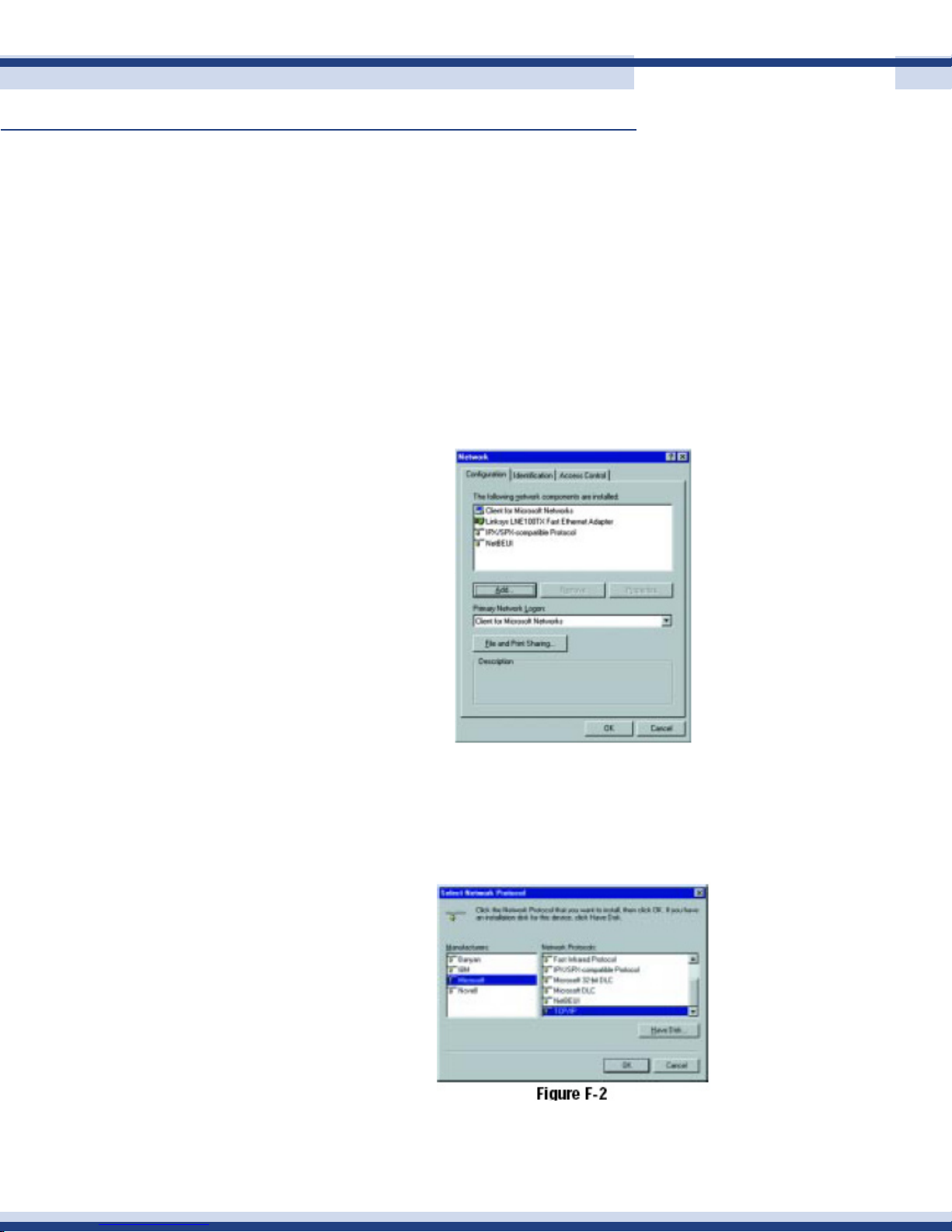
appendix b
85
n installing the tCP/iP ProtoCol
Follow these instructions to install the TCP/IP Protocol on one of your PCs only after a
network card has been successfully installed inside the PC. These instructions are for
Windows 95, 98, and Millennium. For TCP/IP setup under Windows NT, 2000, or XP,
please refer to your Windows documentation.
1. Click the Start button. Choose Settings, and then Control Panel.
2. Double-click the Network icon. Your Network window should pop up. Select the
Conguration tab.
3. Click the Add button.
4. Double-click Protocol.
5. Highlight Microsoft under the list of manufacturers.
6. Find and double-click TCP/IP in the list to the right in Figure F-2.
Version 2.2
Page 86
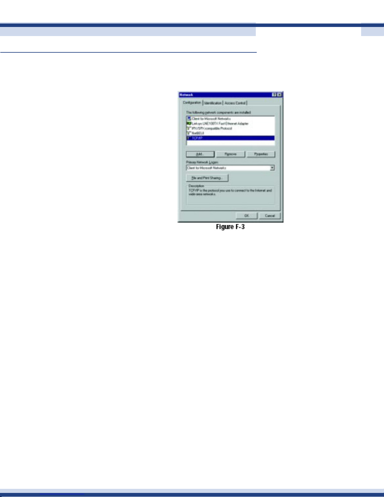
appendix b
86
Continued
7. After a few seconds you will be brought back to the main Network window. The
TCP/IP Protocol should now be listed.
8. Click OK. Windows may ask for original Windows installation les. Supply them as
needed (e.g.: c:\windows\options\cabs, D:\win98, D:\win95, D:\win9x, etc.)
9. Windows will ask you to restart the PC. Click Yes.
The TCP/IP Installation is complete
Version 2.2
Page 87

appendix C
87
n warranty information
This product is covered by a limited warranty for a period of 12 months from date of
purchase.
Version 2.2
Page 88

appendix d
88
n ContaCt information
For help with the installation or operation of this product, contact Cortexa Technology Inc.
Technical Support at [email protected].
Version 2.2
 Loading...