

Page 1
NOTE: This manual may be subject to updates or changes. Up to date manuals are available through our website at www.lifespanfitness.com.au
Product may vary slightly from the item pictured due to model upgrades
Read all instructions carefully before using this product. Retain this owner’s manual for future
reference.
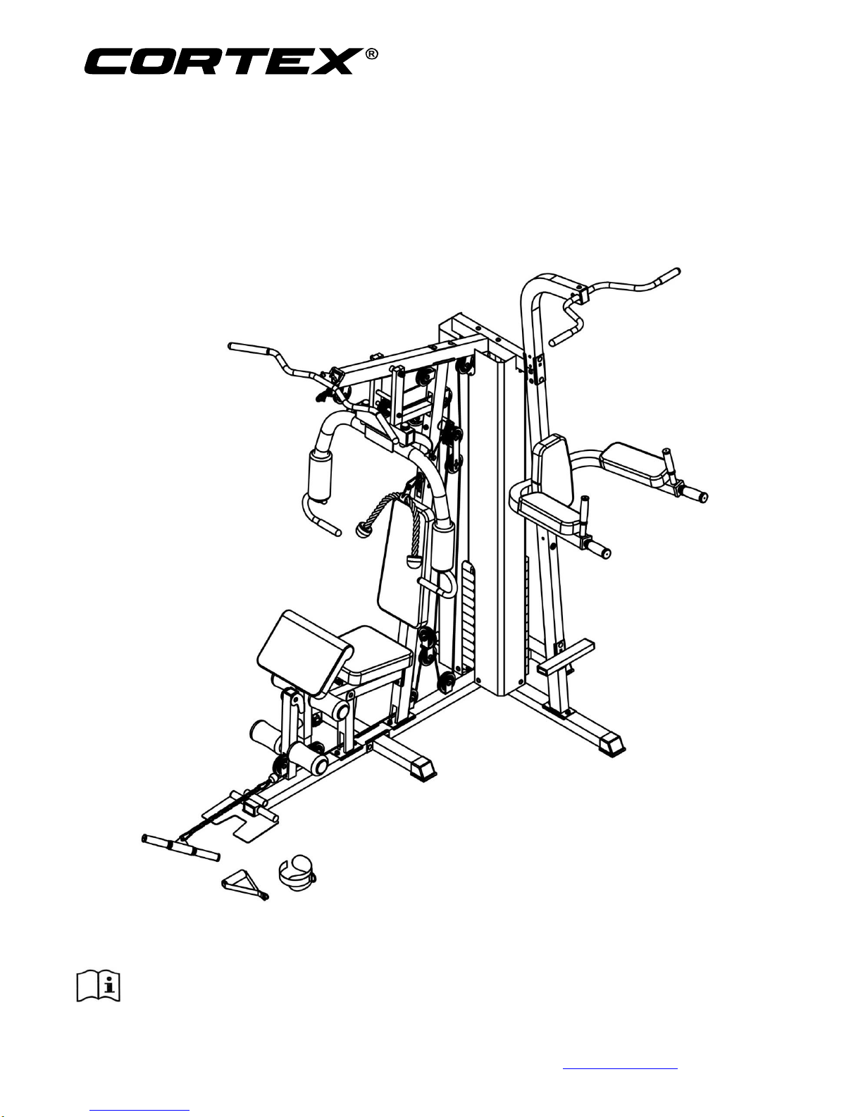
GS6 MULTI STATION OWNER’S
MANUAL
Page 2

2
GS6 MULTI STATION
TABLE OF CONTENTS
1. IMPORTANT SAFETY INSTRUCTIONS 3
2. PARTS LIST 4
3. ASSEMBLY INSTRUCTIONS 8
4. WARRANTY 20
Page 3
3
GS6 MULTI STATION
1. IMPORTANT SAFETY INSTRUCTIONS
WARNING - Read all instructions before using this machine.
Install the product on a flat level surface
Place your unit on a solid, level surface when in use
Never allow children on or near the machine.
Keep hands away from all moving parts.
Never drop or insert any object into any openings.
Care must be taken when lifting or moving the equipment so as not to injure your back. Always use
proper lifting techniques and/or seek assistance if necessary.
Keep children and pets away from the machine at all times. DO NOT leave children unattended in the
same room with the machine.
Only 1 person at a time should use the machine.
If the user experiences dizziness, nausea, chest pain, or any other abnormal symptoms, STOP the
workout at once. CONSULT A PHYSICIAN IMMEDIATELY
Do not use the machine near water or outdoors.
Keep hands away from all moving parts.
Always wear appropriate workout clothing when exercising. DO NOT wear robes or other clothing that
could become caught in the machine. Running or aerobic shoes are also required when using the
machine.
Use the machine only for its intended use as described in this manual. DO NOT use attachments not
recommended by the manufacturer.
Do not place any sharp objects around the machine.
Disabled person should not use the machine without a qualified person or physician in attendance.
Never operate the machine if the machine is not functioning properly.
A spotter is recommended during exercise.
Page 4
4
GS6 MULTI STATION
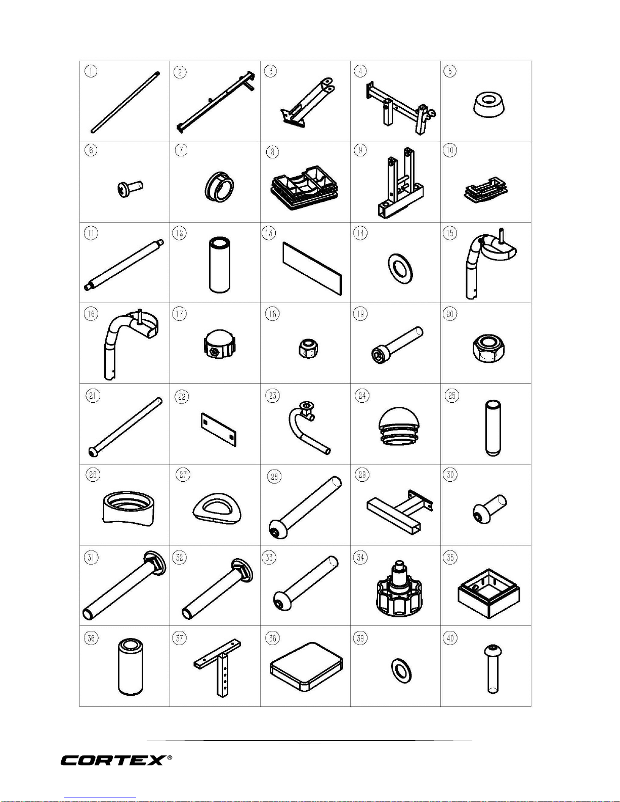
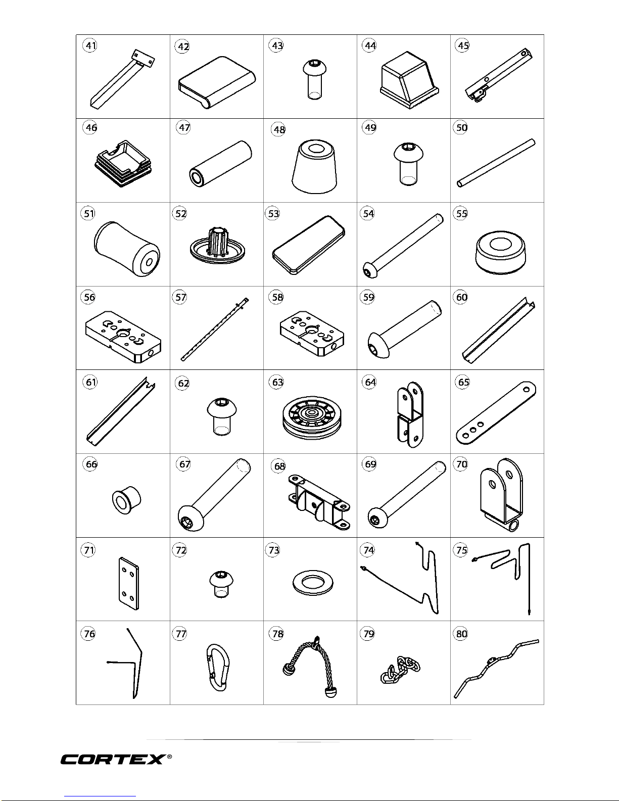
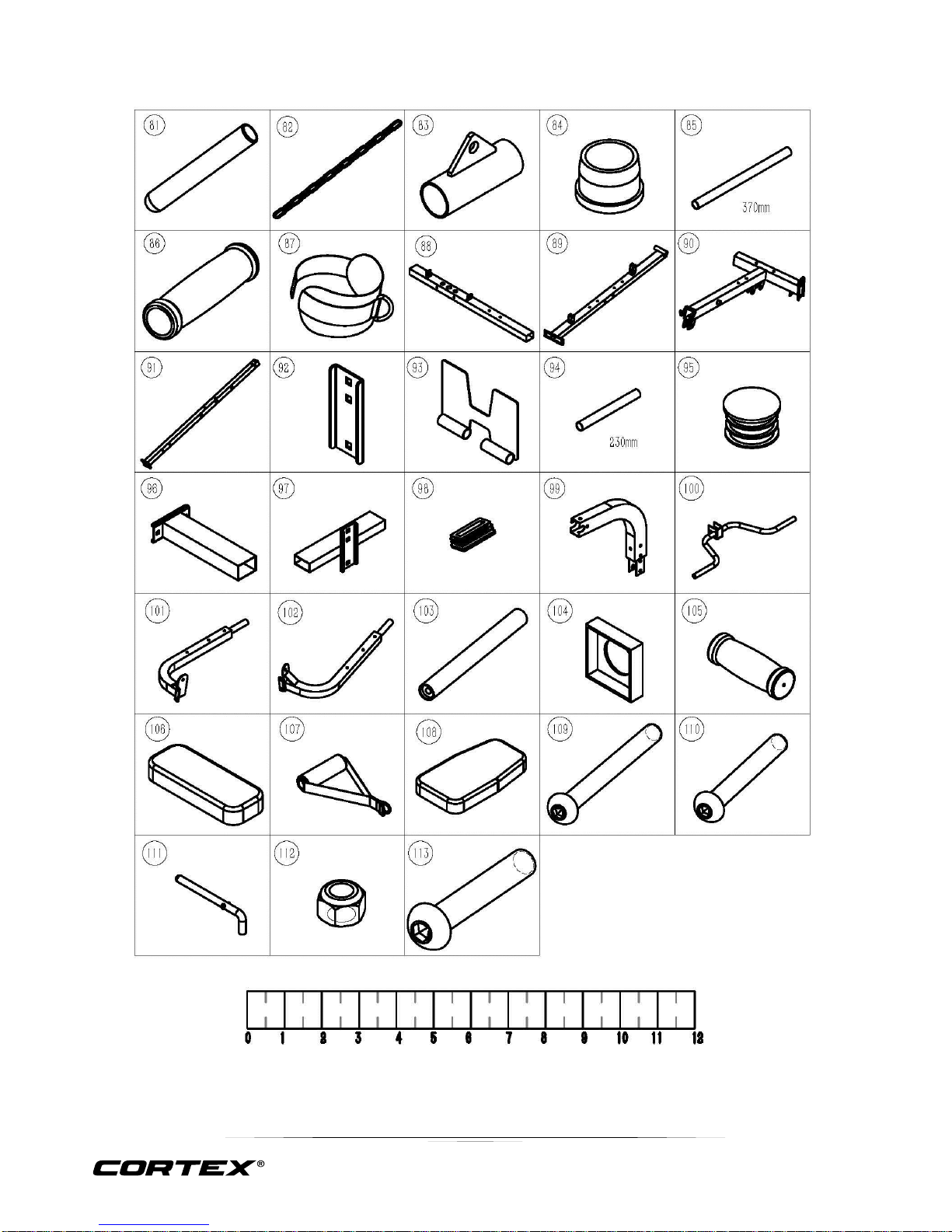
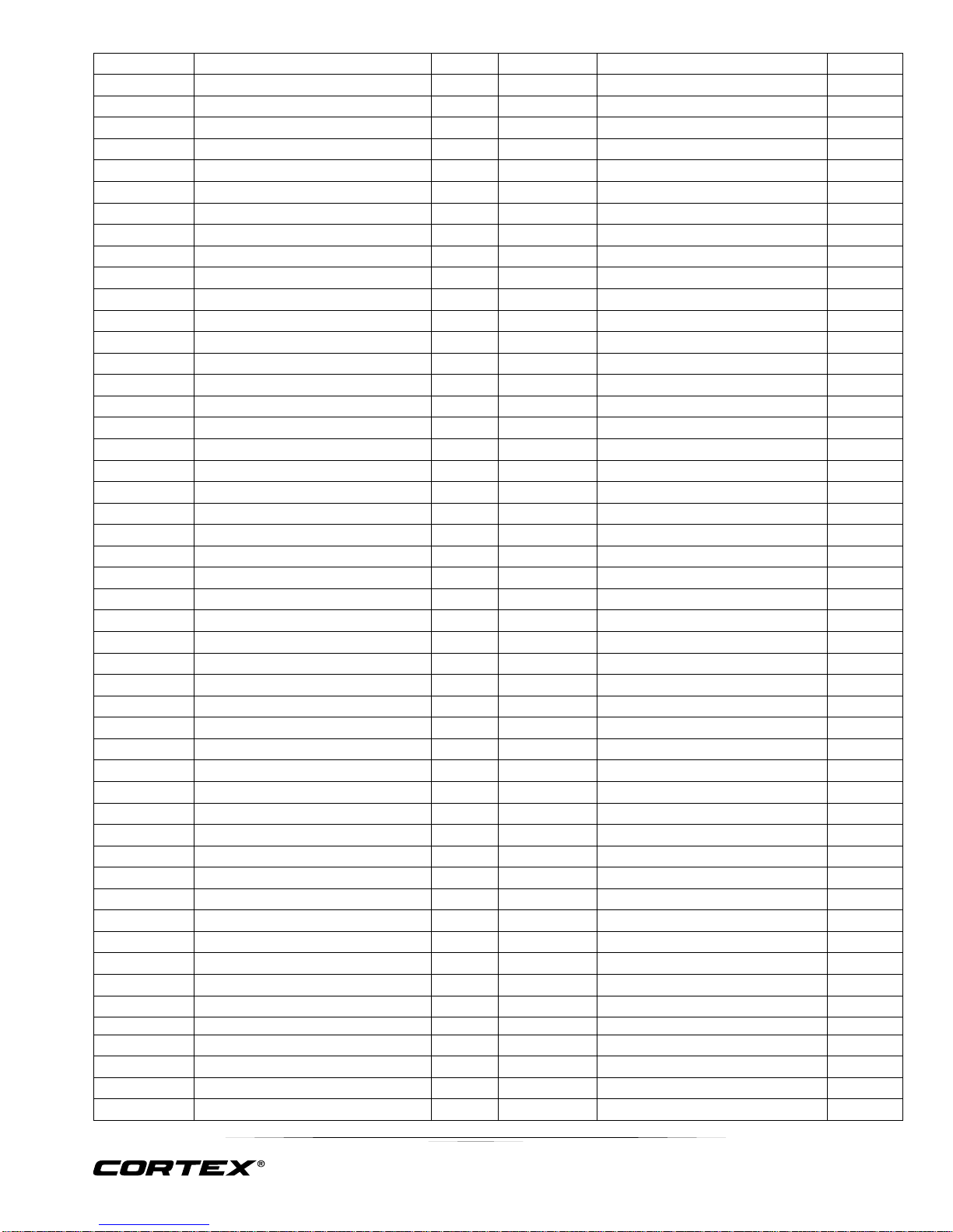
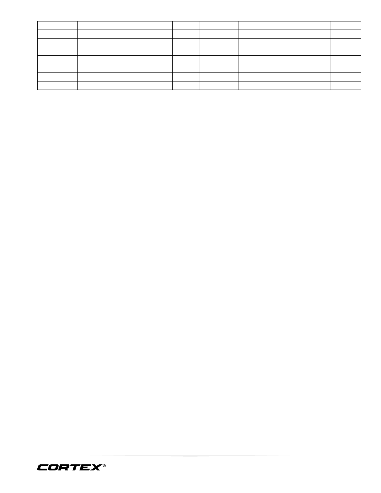
2. PARTS LIST
Page 5
5
GS6 MULTI STATION
Page 6
6
GS6 MULTI STATION
Page 7
7
GS6 MULTI STATION
Key No.
Description
Qty.
Key No.
Description
Qty.
1
Guide Rods
2
58
Selector Stem
1
2
Front Vertical Frame
1
59
Hex Bolt M10x45
16
3
Main Seat Support
1
60
Weight Plate Cover
1
4
Support Tube
1
61
Weight Plate Cover
1
5
Rubber Bumper
1
62
Hex Bolt M10x16
3
6
Bolt M6x16
2
63
Pulley
18
7
PlugΦ25x3xΦ22x7
8
64
Pulley Set
1
8
Plug 50x70
4
65
Pulley Bracket
2
9
Front Press Base
1
66
Pulley Bushing
2
10
Plug 50x25
4
67
Hex Bolt M10x65
3
11
Long Axle
1
68
Pulley Bracket
1
12
Let Developer Axle
1
69
Hex Bolt M10x110
1
13
Adhesive Label
1
70
Pulley Bracket
2
14
Washers Φ10
81
71
Plate (4 holes)
1
15
Left Butterfly Set
1
72
Hex Bolt M8x10
4
16
Right Butterfly Set
1
73
Washers Φ12
2
17
Lock Ring
2
74
Triceps Cable (4040mm)
1
18
Nut M6 2 75
Lat Cable (3450mm)
1
19
Hex Bolt M6x35
2
76
Butterfly Cable 3020
1
20
Nut M10
42
77
C-clip 5 21
Hex Bolt M10x175
1
78
Triceps Rope
1
22
Plat (hole to hole 110mm)
6
79
6 Chain 1 23
Press Bar Set
2
80
Lat Bar 1 24
Plug Φ25
3
81
Bar Grip 2 25
Dipping Sleeve
4
82
15 Chain 1 26
Butterfly Bushing
2
83
Small Bar Set
1
27
Washer 10-R12.5
2
84
Bushing Φ38x5xΦ27x26
2
28
Hex Bolt M10x85
2
85
Small Bar Tube
1
29
Rare Support Tube
1
86
Grip
4
30
Hex Bolt M10x25
6
87
Ankle Strap
1
31
Carriage Bolt M10x90
12
88
Rar Base Frame
1
32
Carriage Bolt M10x70
6
89
Base Frame
1
33
Hex Bolt M10x70
1
90
Upper Frame
1
34
Ring Knob
2
91
Vertical Frame
1
35
Plug 50x45
2
92
Board 1 36
Press Foam
2
93
Foot Plate
1
37
Seat Frame
1
94
Foot Plate Tube 270mm
1
38
Lampstand
1
95
Pipe Bushing
2
39
Washers Φ8
12
96
Support Tube
2
40
Hex Bolt M8x40
2
97
Foot Tube
1
41
Arm Frame
1
98
Tube Plug 60x30
2
42
Arm Pad 1 99
Parallel Support
1
43
Hex Bolt M8x20
2
100
Lat Bar 1 44
Tube Cover
6
101
Left Support Tube
1
45
Leg Developer
1
102
Right Support Tube
1
46
Tube Plug 口 50
1
103
Vertical Tube Bar
2
47
Axle 1 104
Bushing
2
48
Bummper Φ45xΦ35x33
1
105
Pipe Grip 2 49
Hex Bolt M10x20
10
106
Arm Cushion
2
Page 8
8
GS6 MULTI STATION
50
Foam Tube
2
107
Pull Handle
1
51
Foam 4 108
Back Pad
1
52
Foam Cover
4
109
Hex Bolt M8x90
2
53
Back Pad
1
110
Hex Bolt M8x65
4
54
Hex Bolt M8x85
2
111
L-Pin
1
55
Bummper Φ61xΦ58xΦ26x25
2
112
Nut M12
1
56
Weight Plates
13
113
Hex Bolt M12x75
1
57
Selector Rod
1
Page 9
9
GS6 MULTI STATION
3. ASSEMBLY INSTRUCTIONS
NOTE: �
1. Washers are pushed at two ends of bolts.
2. Some parts has been assembled at the factory.
3. It is strongly recommended this machine to be assembled by two or more people to avoid possible
injury.
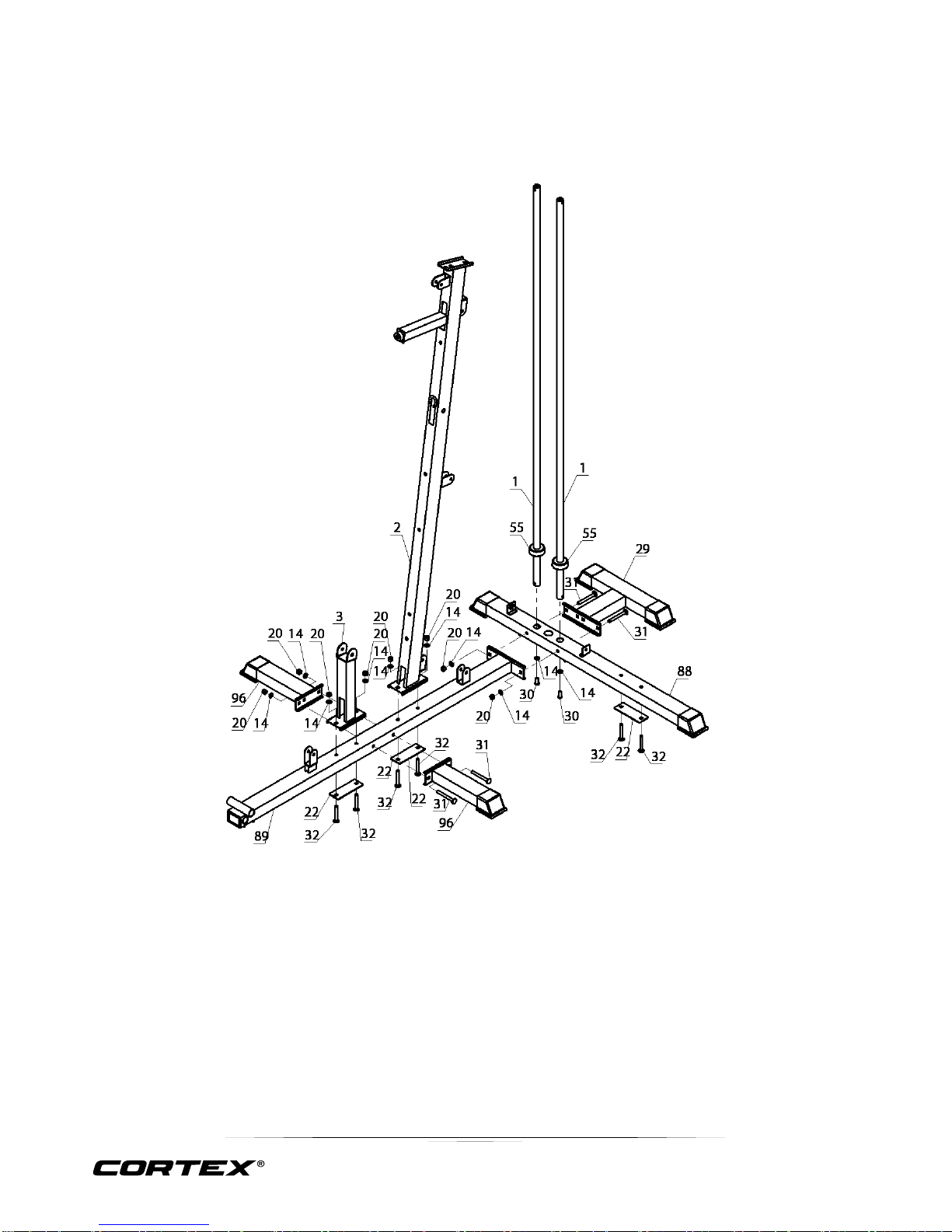
STEP 1
1. Insert the Guide Rode (#1) into the holes on the Main Base Frame (#88). Secure it with 2x Allen Bolt
M10*25mm (#30) and 2x Washer Φ10 (#14).Push the Rubber Dumper (#55) onto the Guide Rods (#1)
2. Attach the Rear Base Frame (#29) to the Front Base Frame (#89) and Main Base Frame (#88). Secure it
with 2x Carriage Bolt M10*90mm (#31), Aircraft Nut M10mm (#20) and 4x Washer Φ10 (#14).
3. Attach the Front Vertical Frame (#2) to the Front Base Frame (#89). Secure it with 2x Washer Φ10 (#14)
and 2x Aircraft Nut M10mm (#20), 2x Carriage Bolt M10*70mm (#32) and Bracket (#22).
4. Attach the seat support tube (#3) to the Front Base Frame (#89), secure with 2x Washer Φ10 (#14) and
2x Aircraft Nut M10mm (#20), 2x Carriage Bolt M10*70mm (#32).
5. Attach the Left and Right Base Tube (#96) to the Front Base Frame (#89). Secure it with 2x Carriage Bolt
M10*90mm (#31), 4x Washer Φ10 (#14) and 2x Aircraft Nut
Page 10
10
GS6 MULTI STATION
STEP 2
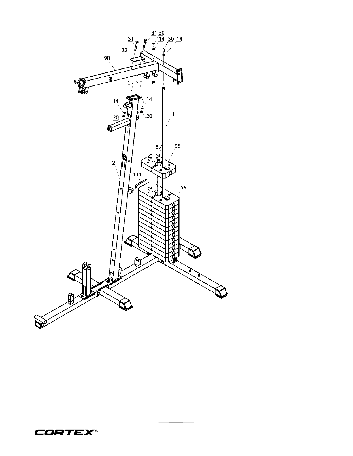
1. Slide the 13 Weight Plates (#56)
onto the Guide Rods (#1). (Note:
The groove side faces down).
Insert the Selector Rod (#57)
through the centre hole.
2. Slide the Selector Stem (#58) onto
the Guide Rod (#1). Insert the Lshaped Pin (#111).
3. Attach the Upper Frame (#90) to
the Guide Rods (#1). Secure it with
2x Allen Bolt M10*25mm (#30) and
2x Washer Φ10 (#14).
4. Secure the Upper Frame (#90) to
the Front Vertical Frame (#2) with
2x Carriage Bolt M10*90mm (#31),
2x Washer Φ10 (#14), Bracket
(#22) and 2x Aircraft Nut M10mm
Page 11
11
GS6 MULTI STATION
STEP 3
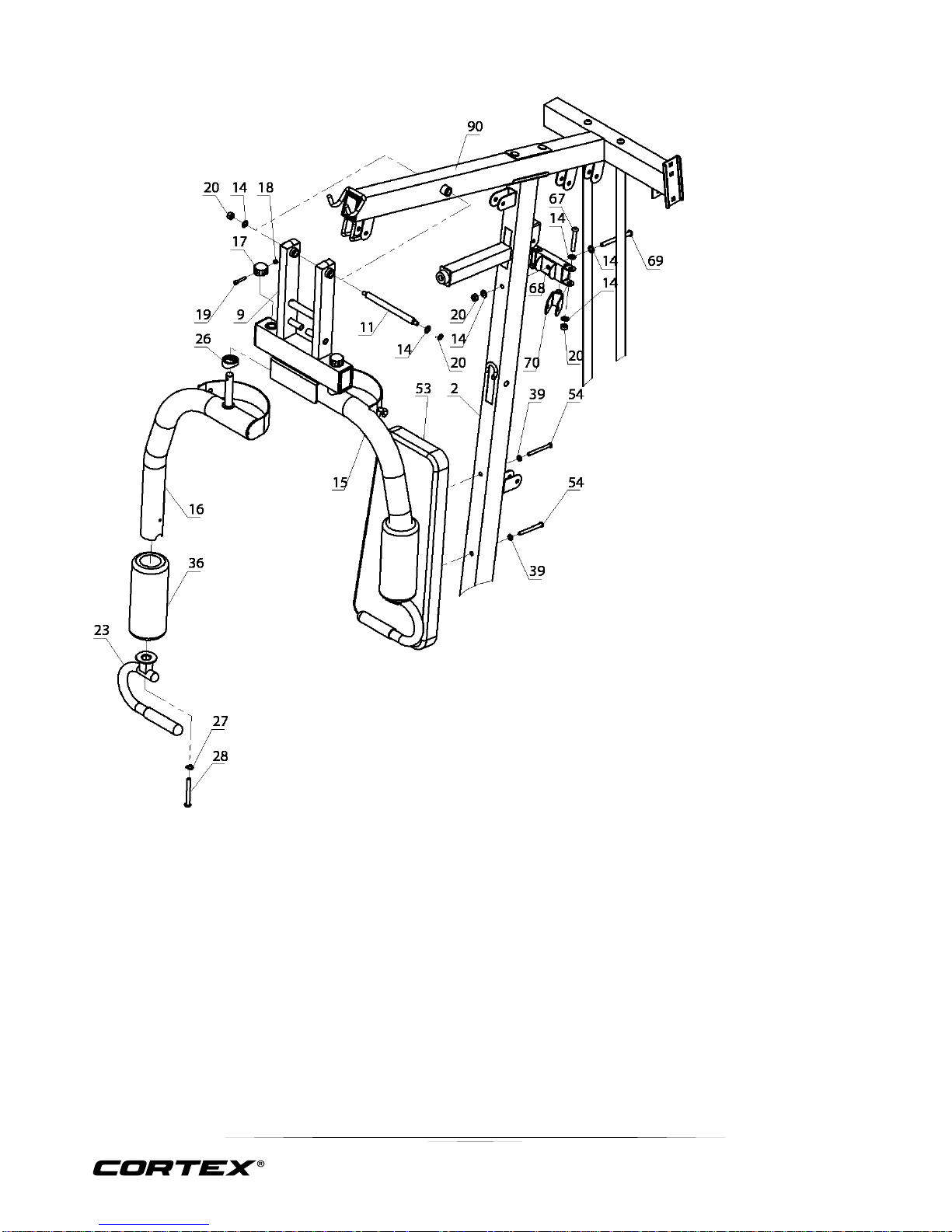
1. Attach the Front Press Base (#9) to the Upper Frame (#90). Secure it with 1x Long Axle (#11), Washer
(#14) and Aircraft Nut M10mm (#20).
2. Slide a Butterfly Foam Roll (#36) onto the Butterfly arm (#16) and (#15). Attach the 2x Front Press Handle
(#23) to the Left & Right Butterfly (#16 & #15) with Allen Bolt M10*85mm (#28) and Washer Φ10 (#27).
3. Attach the Butterfly arm (#16) and (#15) to the Front Press Base (#9), secure them with Butterfly Bushing
(#26), Aircraft Nut M6mm (#18) and Lock Ring (#17), Bolt M6*35mm (#19).
4. Attach the Pulley Bracket (#68) to the Front Vertical Frame (#2), secure with Hex bolt (#69), Washer (#14)
and Aircraft Nut M10mm (#20). Attach the pulley bracket (#70) to the (#68), secure with Hex Bolt M10x65
(#67), Washer (#14) and Aircraft Nut M10mm (#20).
5. Attach the Back pad (#53) to the Front Vertical Frame (#2), secure with Hex Bolt M8x85 (#54), Φ8Washer
(#39).
Page 12
12
GS6 MULTI STATION
STEP 4
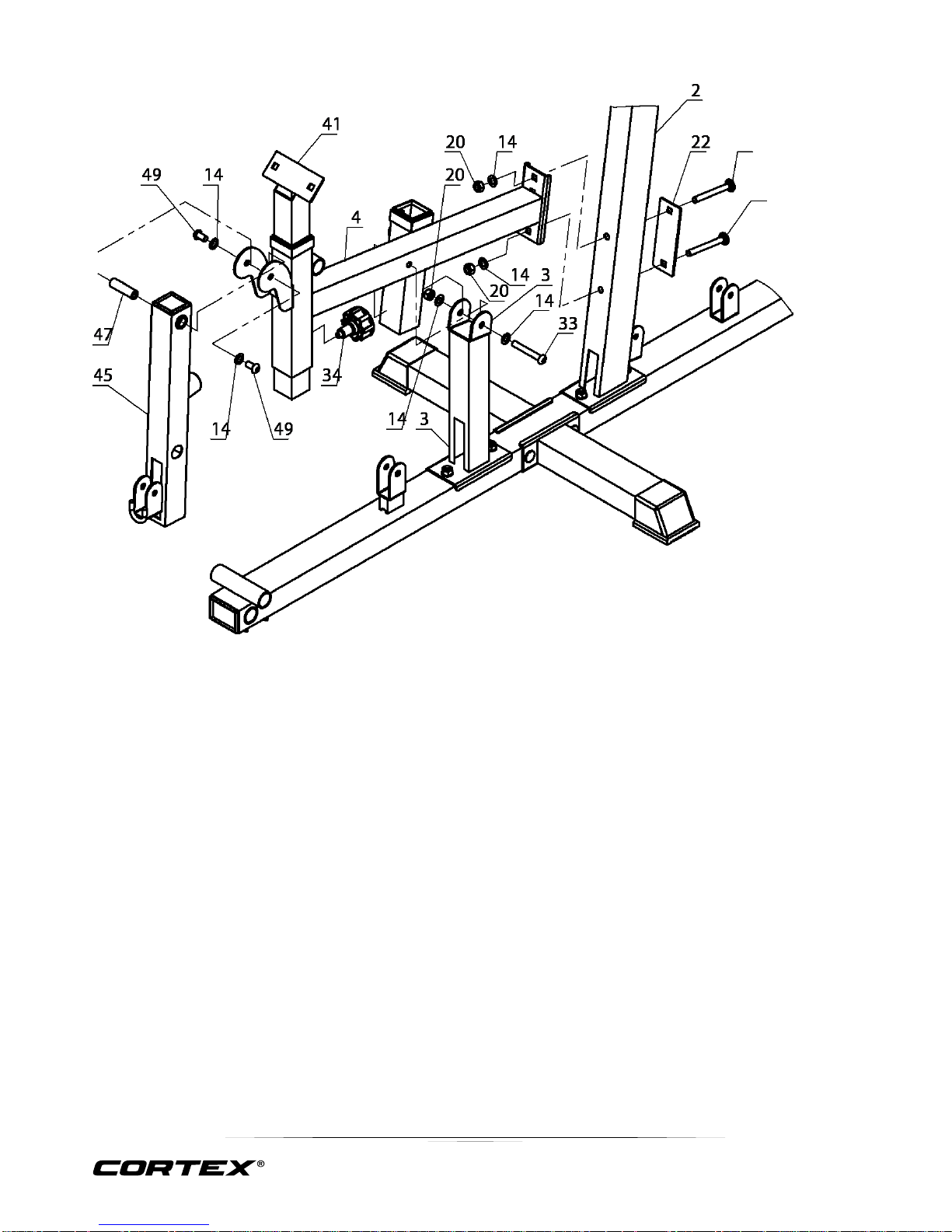
1. Attach the Main Seat Support (#4) to the Front Vertical Frame (#2). Secure it with Washer Φ10 (#14) and Aircraft
Nut M10mm (#20), Carriage Bolt M10*90mm (#31), and Plate (#22).
2. Attach the Main Seat Support (#4) to the Front Base Frame (#3). Secure it with Washer Φ10 (#14) and Aircraft Nut
M10mm (#20), Hex Bolt M10x70.
3. Attach the Leg Developer (#45) to the Main Seat Support (#4). Secure it with a Leg Developer Axle (#47), Allen Bolt
M10*20mm (#49) and Washer Φ10 (#14).
4. Attach Lock Knob (#34) to Main Seat Support (#4). Insert the Tube (#41).
Page 13
13
GS6 MULTI STATION
STEP 5
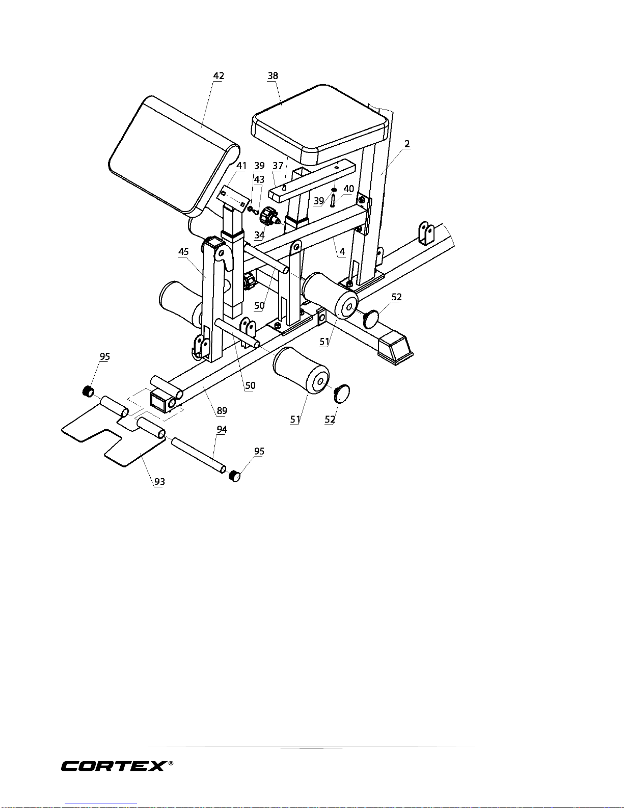
1. Place the Seat (#38) onto the Seat Stand (#37). Secure it with Allen Bolt M8*40 (#40) and WasherΦ8 (#39).
Insert the Seat Stand (#37) into the Main Seat Support (#4). Secure it with Lock Knob (#34).
2. Attach the Arm Curl Pad (#42) to the Arm Curl Stand (#41). Secure it with Allen Bolt M8*20mm (#43) and
Washer Φ8 (#39).
3. Insert 2x Foam Tubes (#50) halfway through the holes on the Leg Developer (#45) and the Main Seat Support
(#4), push Foam Rolls (#51) onto the Foam Tubes (#50) from both ends. Plug the 4x Foam Roll End Caps
(#52) onto the ends.
4. Attach the Foot Plate (#93) to the Front Base Frame (#89), secure with Tube (#94), then plug the two Caps
(#95).
Page 14
14
GS6 MULTI STATION
STEP 6
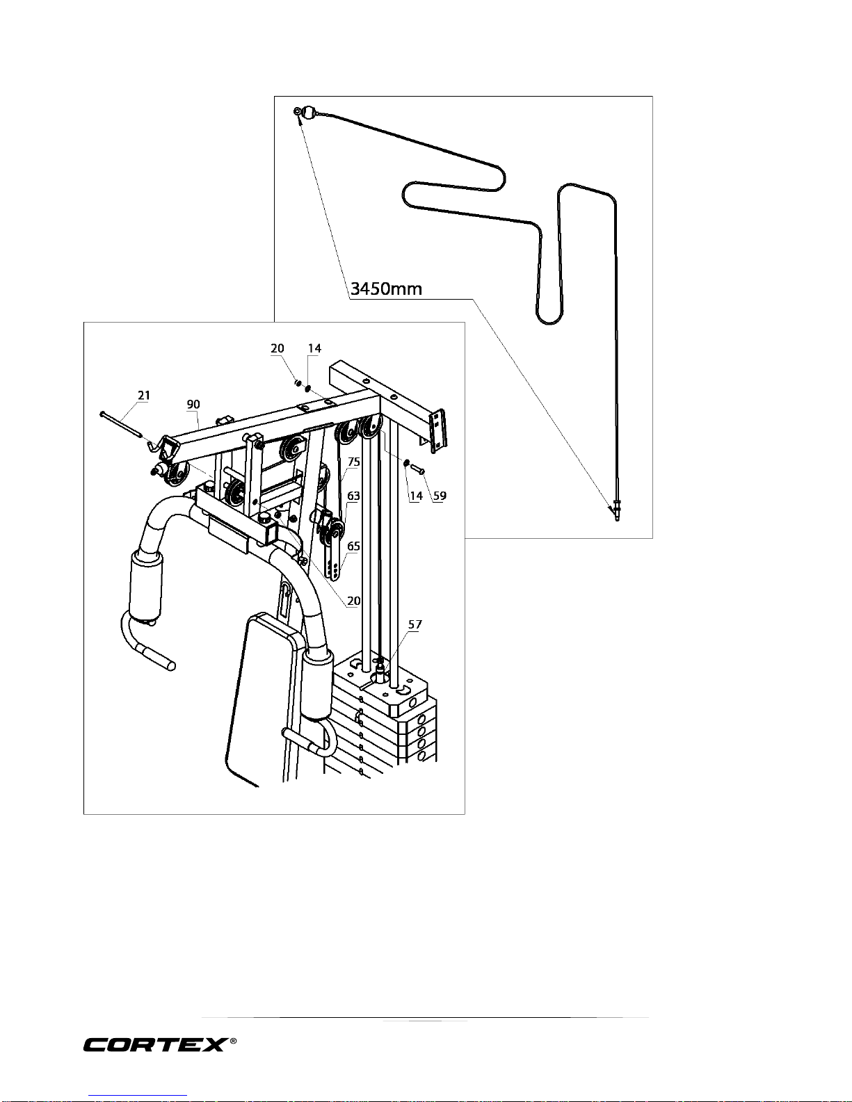
1. Feed the Lat Cable (3450mm)(#75) through 7 xPul ley ( #63) as shown in im age following, secure with 12 Washers Φ10 (#14), 6 H ex BoltsM10 ×45 (#59) , 1 Hex Bolt M10x175(#21), 7 Nu t M10 (#20) , 2 Pulley plate (#65). Connec t the end whic h is bolt to the(#57).
1. Feed the Lat Cable (3450mm)(#75) through 7x Pulley (#63) as shown in image following, secure with 12
Washers Φ10 (#14), 6 Hex BoltsM10×45 (#59), 1 Hex Bolt M10x175(#21), 7 Nut M10 (#20), 2 Pulley plate
(#65). Connect the end which is bolt to the (#57).
Page 15
15
GS6 MULTI STATION
STEP 7
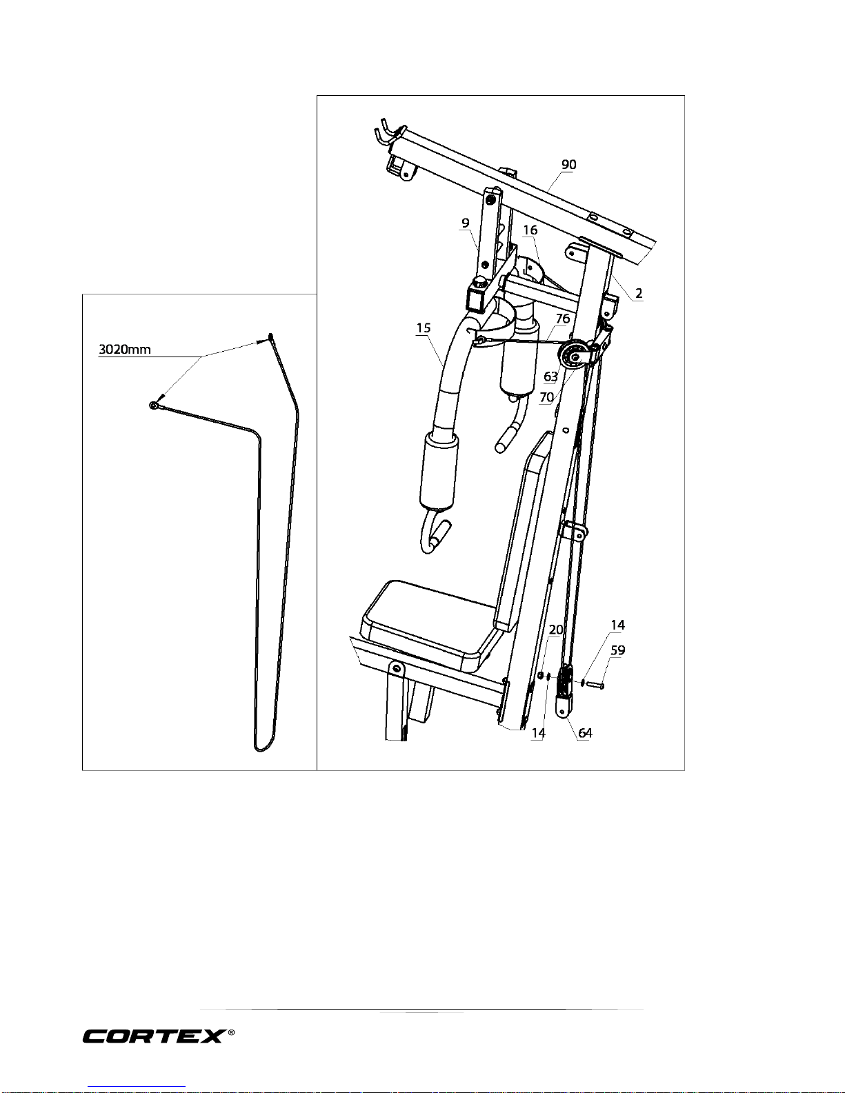
1. Connect the Butterfly Cable (3020mm) (#76) to Right Butterfly (#16) and Left Butterfly (#15) as shown in
image, secure with 1 Pulley Set(#64), 3 Pulley (#63), 3 Hex Bolts M10x45 (#59), 6 Φ10 washers (#14), 3
Nuts(#20).
Page 16
16
GS6 MULTI STATION
STEP 8
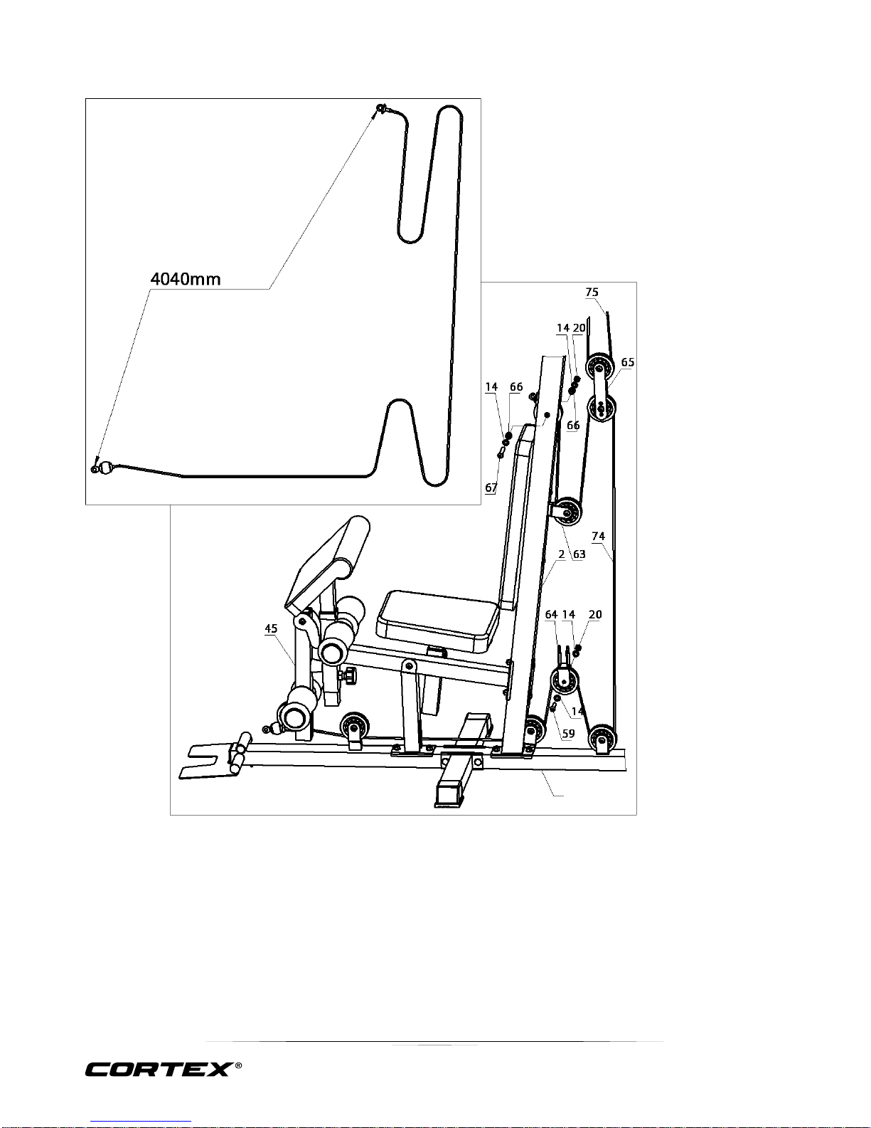
1. Fix the Triceps Cable (4040mm) (#74) as shown in image, secure with 2 Pulley Set(#66), 8 Pulley (#63), 7
Hex Bolts M10x45 (#59), 1 Hex Bolt M10x65 (#67), 16 Φ10 washers (#14), 8 Nuts(#20).
Page 17
17
GS6 MULTI STATION
STEP 9
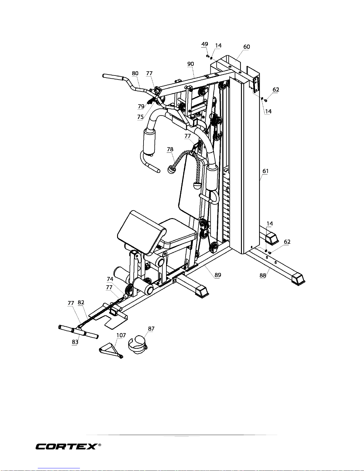
1. Attach Right Weight Plate Cover (#60) and (#61) to frame (#88) and (#90), secure with 1 M10x20
(#49), 1 Hex Bolt M10x16mm (#62), 2 WashersΦ10 (#14) and Aircraft Nut M6mm (#56).
2. Attach Lat Bar (#80) to the Lat Cable (3450mm) (#75) though 6 Chains (#34) with 2 C-clip (#77).
3. Attach Small Bar Set (#80) to the Triceps Cable (4040mm) (#74) though 15 Chains (#82) with 2 Cclip (#77).
Page 18
18
GS6 MULTI STATION
STEP 10
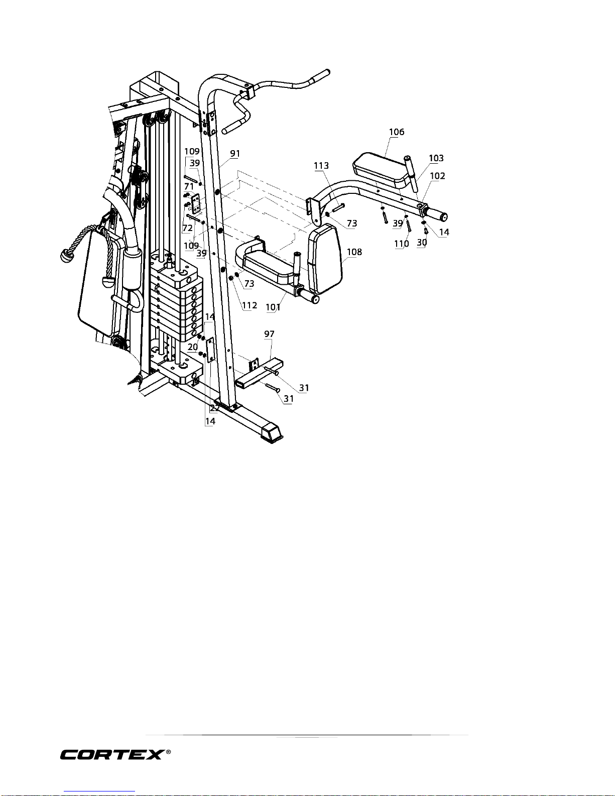
1. Attach the Left Dip Arm (#101) and the Right Dip Arm (#102) to the Vertical Frame (#91). Secure it with 1x
Carriage Bolt M12*75mm (#113), 2x Washer Φ10 (#73), 1x Aircraft Nuts M12mm (#112). Connect the two
arms (#101) and (#102) together by 4 Hex Bolts M8x10 (#72), 4 washers Ф8 (#39), 1 Plate (4 holes) (#71).
2. Plug the Handle Bar (#103) into the hole of Right Dip Arm (#101) and (#102) with 2 Hex bolts M10x25 (#30).
3. Attach the Arm Pad (#106) to the Right and left Dip Arm. Secure it with 4 Allen Bolts M8*65mm (#110), 4x
WasherФ8 (#39).
4. Attach the Padded Back Support (#108) to the Vertical Frame (#91). Secure it with 2x Allen Bolts M8*90mm
(#109), 2x Washer Ф8 (#39).
5. Attach the Foot Stand (#97) to the Vertical Frame (#91). Secure it with 2x Carriage Bolt M10 x 90mm (#31),
bracket (#22), 2x Washer Φ10 (#14), 2x Aircraft Nuts M10 (#20).
Page 19
19
GS6 MULTI STATION
STEP 11
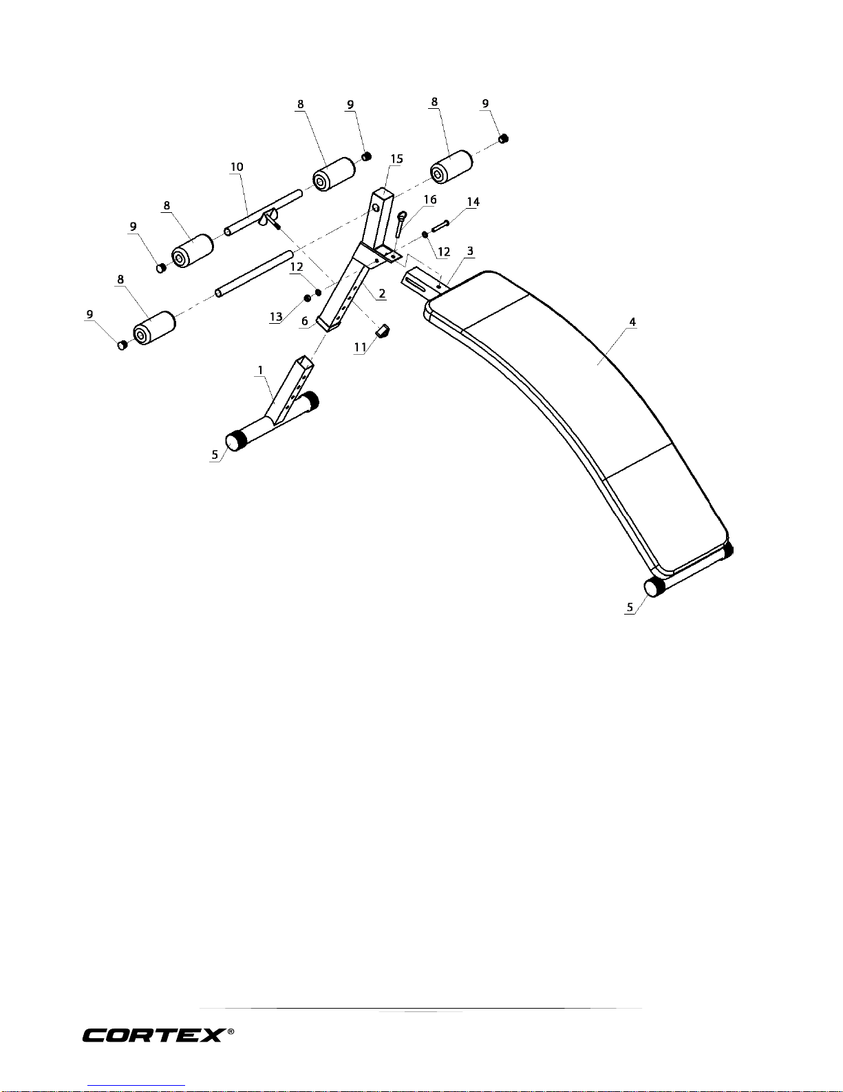
1. Attach 1x Arch Frame (#3) to the Front Vertical Stand (#2). Secure it with 1x Carriage Bolt M10 x 70mm (#14),
2x Washerφ10 (#12) and 1x Allen Bolt M10mm (#13).
2. Attach the 1x Base Frame (#1) to the Front Vertical Stand (#2). Adjust the height and secure it with 1x
Adjustable Position Foam Tube (#10) and 1x Lock Knob (#11).
3. Push 4x Foam Rolls (#8) onto Long Foam Tube (#7) and Adjustable Position Foam Tube (#10).
4. Put Plus (#9) onto the two ends of Long Foam Tube (#7) and Adjustable Positional Foam Tube (#10).
5. Check that all the parts is tight.
Page 20
20
GS6 MULTI STATION
4. WARRANTY
AUSTRALIAN CONSUMER LAW
Many of our products come with a guarantee or warranty from the manufacturer. In addition, they come with
guarantees that cannot be excluded under the Australian Consumer Law. You are entitled to a replacement
or refund for a major failure and compensation for any other reasonably foreseeable loss or damage.
You are entitled to have the goods repaired or replaced if the goods fail to be of acceptable quality and the
failure does not amount to a major failure. Full details of your consumer rights may be found at
www.consumerlaw.gov.au
Please visit our website to view our full warranty terms and conditions:
http://www.lifespanfitness.com.au/warranty-repairs
Warranty and Support:
Please email us at [email protected] for all warranty or support issues.
For all warranty or support related enquiries an email must be sent to lodge a support case in our system.
Head Office and Customer Service:
Global Fitness and Leisure Pty Ltd
17 Fordson Rd
Campbellfield
VIC, 3061
Australia
PH: 03 9357 2166
 Loading...