

Page 1
Datalog 3 - SMS Software A pplicat ion Sheet
Microtech Galaxy 500/512 Panel
Introduction
This Datalog 3 software version has been modified to incorporate a driver to comm unicate with
Ademco Microtech Galaxy alarm panels 500 and 512 (V1.25 or later). The pa nel must have an
RS232 module fitted ( V1.20 or later). T he Galax y panel can be connec ted direct ly to a Data log PC
in local mode where the Datalog has control over the Galaxy panel or remotely via a
communication dev ice such as Adpro VST-10 or DVST, wher e the Datalog will only monitor the
panel. In both insta nces, keypad em ulation is available to a llow programm ing and set/res et of the
panel from the PC.
Installation
Connections
The alarm system needs to be installed as per manufacturer's requirements with the RS232
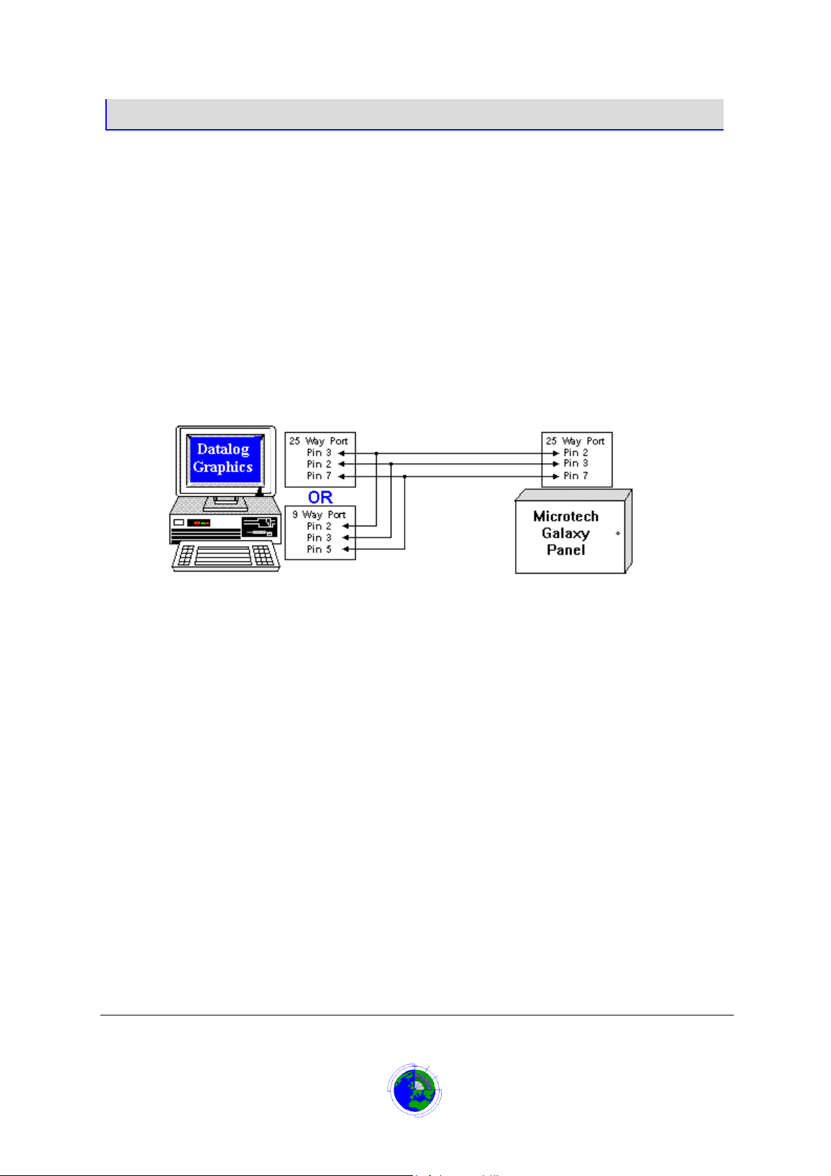
module on line 1. A cable sho uld be inst alled bet ween the Dat alog P C Com m Port and the Ga laxy
Panel’s RS232 module using the connections in the diagram below.
The default speed for communications to the Galax y is 9600 baud, at this setting the cable length
should not exceed 15 Metres unless a line dri ver is used. The defau lt settings for communication
are 9600 Baud, 8 Data bits, 1 Stop B it and No Pari t y. For th is c onf igura tio n, the dip switches on t he
RS232 module should be:
1,2,3,4,5,7 Off
6,8 On
Communication Baud rat e and parity Settings can be chan ged in the Data log’s initia lisation f iles to
suit remote configurations.
Module Tamper alarms
The panel is unable to report module tamper alarms directly to the Datalog when directly
connected, to achieve this the tamper switch must be wired to an input on a RIO.
Configuring Panel
Once communic ation is setup, the Datalo g PC wil l configur e the zones on the panel for alarm t ype
and enter the first 16 characters of the Datalo g zone description as the Galaxy zo ne description.
The system will set a ll zones to the ‘26=LOG’ alarm type unless requested otherwise. The LOG
alarm type guarantees sending all alarms regardless of the set/unset condition of the panel
.
Microtech Galaxy 500/512 Panel
Page 1 of 8
CORTECH DEVELOPMENTS LTD
Downloaded from: http://www.guardianalarms.net
Page 2

Datalog 3 - SMS Software A pplicat ion Sheet
Panel Programming
The Panel Communications
Enter Engineers mode with default passcode 112233 [ent]
On a Galaxy 512 the engine er’s code may have to be enable d first. (Managers password
then option 48)
Select Option 56=COMMUNICATION [ent]
Select 2=RS232 [ent]
Select 1=MODE [ent]
Select 1=Direct [ent]
Select 2=FORMAT [ent]
Select 2=Microtech [ent]
The keypad will the n display 16 alarm type options for triggering alarm messages to be output to
the Panel’s Log.
If the panel is to be used as a remote dial-up unit then the following triggers
12 MODULES/COMMS ON
13 ELEC.STATUS ON
15 TROUBLE ON
16 LOG ON
All others should be set to OFF unless a different alarm type is used.
To change:
Select trigger type with A or B keys [ent]
Press 1 for ON or 2 for OFF [ent]
Press [esc]
To exit this option:
Press [esc] until 56=COMMUNICATION is displayed.
must
be programmed for RS232 configuration as follows:
must
be set to ON:
Also if the panel is to be used as a remote dial-up unit, t he cor r ect ac c ou nt c od e must be assigned.
To do this:
Select Option 56=COMMUNICATION [ent]
Select 2=RS232 [ent]
Select 3=ACCOUNT Number [ent]
Enter panel number preceded by zeros to a maximum of 6 characters [ent]
e.g. 000001 for panel 1, 000011 for panel 11.
Press [esc] until 56=COMMUNICATION is displayed.
Enable Groups
The Datalog system is able to ut ilise t he Galax y Panel gr oups f eature. In order to achieve this, the
panels Group function must be enabled. To enable groups:
Select Option 63=PROGRAM O/P [ent]
Select 1=Groups [ent]
Select 1=Group mode [ent]
Press 1 to enable [ent]
To exit this option:
Press [esc] until returned to Engineer Mode banner.
See Also Groups
Microtech Galaxy 500/512 Panel
Page 2 of 8
CORTECH DEVELOPMENTS LTD
Page 3
Datalog 3 - SMS Software A pplicat ion Sheet
Completing Setup
If the panel is directl y connected (a Local panel) then the Datalog system will progr am the panel
with zone and output data, it will assign the zones to groups and autom atically switch outputs on
alarm. If the panel is to be used as a remote dial-up unit then the panel will have to be fully
programmed by the installer, with its own zone input and output data, outputs will have to be
switched using links.
Do not change the Remote passcodes.
Remember to enable the batteries on the main panel PCB (SW1 link) and the RS232 module (SW1
Link) so that the programmed data remains in memory if power fails.
Finally ensure that the panel is not left in Engineer mode by:
Press [esc] until ENGINEER MODE is displayed
Enter Engineer Passcode [esc]
If the panel is left in Engineer mode tamper alarms will not be reported
.
Operation
Initialisation
On program start-up any directl y connected pane ls will be in itial ised. Ini tial isation c an tak e up to 1 3
minutes for each panel depending on the number of zones per panel setup value.
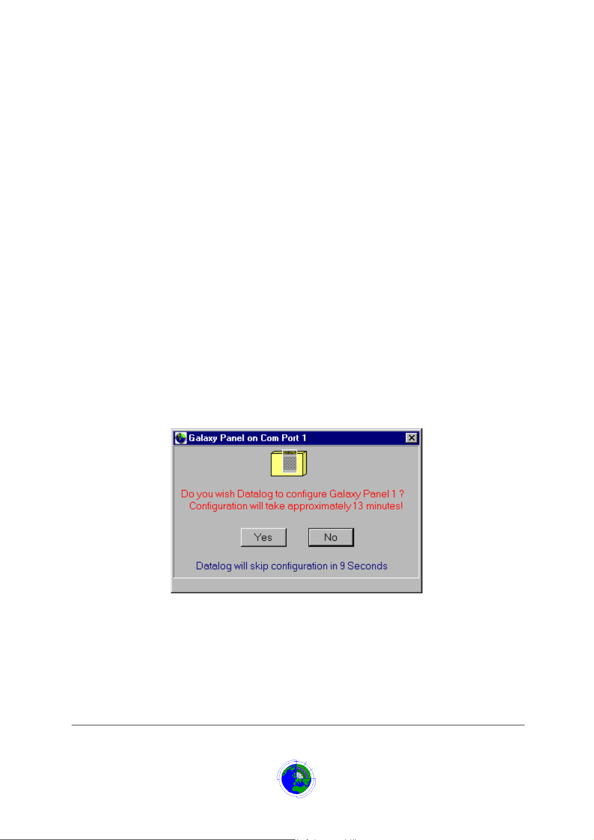
On start-up a form is displayed that will allow 10 sec onds to decide whether to program the panel
or not. If the Yes button is clicked before the 10 seconds completes then initialisation begins,
otherwise if the No button is clicked or th e 10 seconds elaps es then initialisa tion is skipped apar t
from setting the panels time and date.
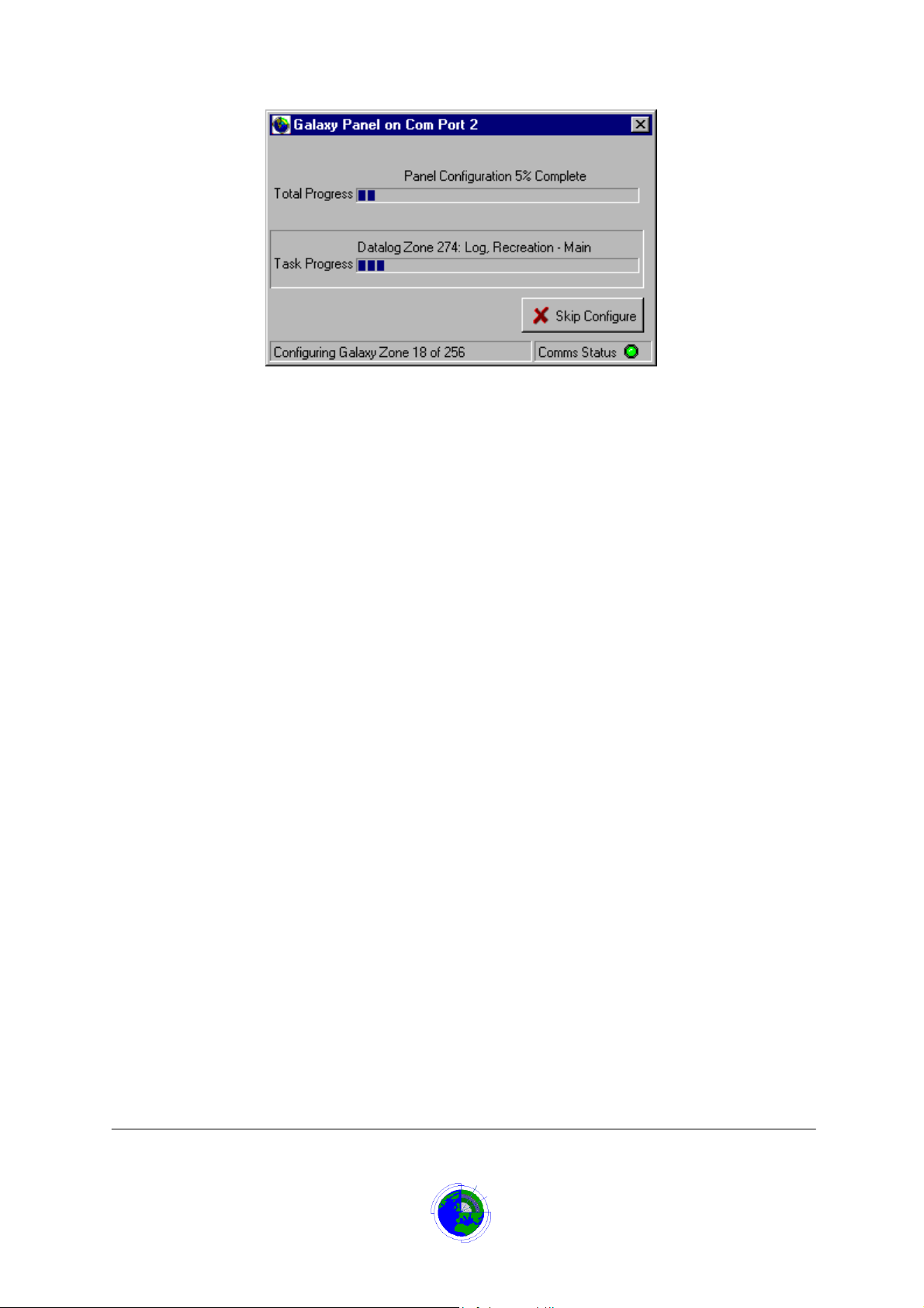
If the Yes button is clicked within the 10-s econ d per iod, init ia lisat ion wi ll dis pla y a for m showing the
progress of configuration for the Galaxy alarm panel.
Microtech Galaxy 500/512 Panel
Page 3 of 8
CORTECH DEVELOPMENTS LTD
Page 4
The initialisation procedure will:
•
Program all zones to a specific type (normally LOG type).
•
Give each zone a description using the first 16 characters of the Datalog zone text.
•
Program all relays on the panel to a specific type, Attribute and polarity.
•
Synchronise the panel’s date and time to the Datalog system’s time.
•
Reset all output relays.
Datalog 3 - SMS Software A pplicat ion Sheet
At any time, the panel configuration can be aborted by clicking the Skip Configure button, which will
cause the initialisation to skip to setting the panel’s date and time and exiting. This form will
disappear when the panel’s configuration is complete.
If more than one panel exists on the system, then this procedure is repeated for each panel.
If panel initialisation is skipped the following still occur:
•
Synchronise the panel’s date and time to the Datalog system’s time.
•
Reset all output relays.
Operation
If the Galaxy panel is connected directl y to a Datalog PC then when the Datalo g 3 application is
started the Galaxy Panel will be initialised. If the Galaxy panel is connected remotely via a
communication device suc h as Adpro V ST - 10 or DVST , then the panel will ha ve t o b e pro gr am med
via its own keypad.
When communication is started following initialisation on a dir ect connect system , the system wil l
check the state of each zone, and if not secure , alarms will b e annunciated b y the Datalog. W hen
communication is s tarted f ollo wing a d ial-up link , if rem ote, the Data log will re ad t he event log f rom
the Galaxy panel and annunciate alarm, short, tamper and reset conditions on the graphical
display.
In addition fault alarms will be reported for panel and module tamper conditions, module
disconnection and b attery failures. Should c ommunication be lost with a panel, a Comm unication
failure alarm will occur and the failure will be flashed on the s ystem status bar. T he alarm will b e
repeated every 15 minutes while communications are lost.
An option is available, mainly for engineering test purposes to program a panel via a Remote
Keypad, switch output relays and read the events log as it is transmitted to the Datalog.
Microtech Galaxy 500/512 Panel
Page 4 of 8
CORTECH DEVELOPMENTS LTD
Page 5
Datalog 3 - SMS Software A pplicat ion Sheet
Groups
The Datalog allows for up to 100 input gr oups to be assigned to th e system with a text descr iption
to identify the group when disp layed on th e Input Gr oup form . The m ain purp ose of the group is t o
inhibit or activate al l the zones in that gro up. The Galaxy panel has 1 6 groups for a Galaxy 500,
and 32 groups for a Ga laxy 512. It is possible to s ynchronise Datalog grou ps with Galaxy Pa nel
groups. This will al low the Datalog zones within the Da talog group to be Acti ve/inhibited when the
Panel’s group is Set/Unset.
To do this requires the Data log ed itor pr ogram or the infor m ation being passed to the ins tall er pr ior
to installation. W hen adding Datalog Inp ut Groups, the Input Grou p description m ust be preceded
with a ‘#’ character followed by the panel number, then a ’G’ character followed by the group
number, followed by a space character, e.g. #1G3 First Floor Alarms, #2G12 Stores Alarms.
The Datalog group is then assigne d to the individual zones that are members of that group. On
panel initialis ation t he Pan el in put is assign ed to the re levant P anel gro up. Onc e ass igned the n th e
Datalog group and its mem ber zones will be inhibited when the Pane l’s group is Unset, and ac tive
when the panel’s group is Set.
Any zones assigned to a Datalog group with no prec eding panel identifier, or not assigne d to any
group will default to being on Panel Group 1. However, the active/i nhibit state of these zo nes will
not be affected by the Setting/Unsetting of Panel Group 1
.
Remote Keypad
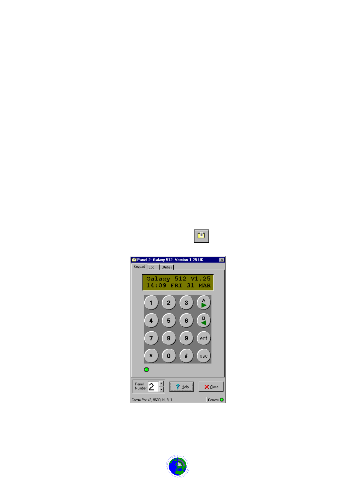
An option is available, mainl y for eng ineering p urposes t o progr am panels , which will switc h output
relays and read the events log as it is transmitted to the Datalog. To use this option, sign on with an
appropriate password and cho ose ‘Galaxy’ from the ‘Tools’ m enu or press the speed button with
the Microtech panel/keypad lo go
The Galaxy form will display press the Keypad tab if the form is not as below:
.
Microtech Galaxy 500/512 Panel
Page 5 of 8
CORTECH DEVELOPMENTS LTD
Page 6
Datalog 3 - SMS Software A pplicat ion Sheet
Log Tab Sheet
An option is available, mainl y for eng ineering p urposes t o progr am panels , which will switc h output
relays and read the events log as it is transmitted to the Datalog. To use this option, sign on with an
appropriate password and cho ose ‘Galaxy’ from the ‘Tools’ m enu or press the speed button with
the Microtech panel/keypad lo go.
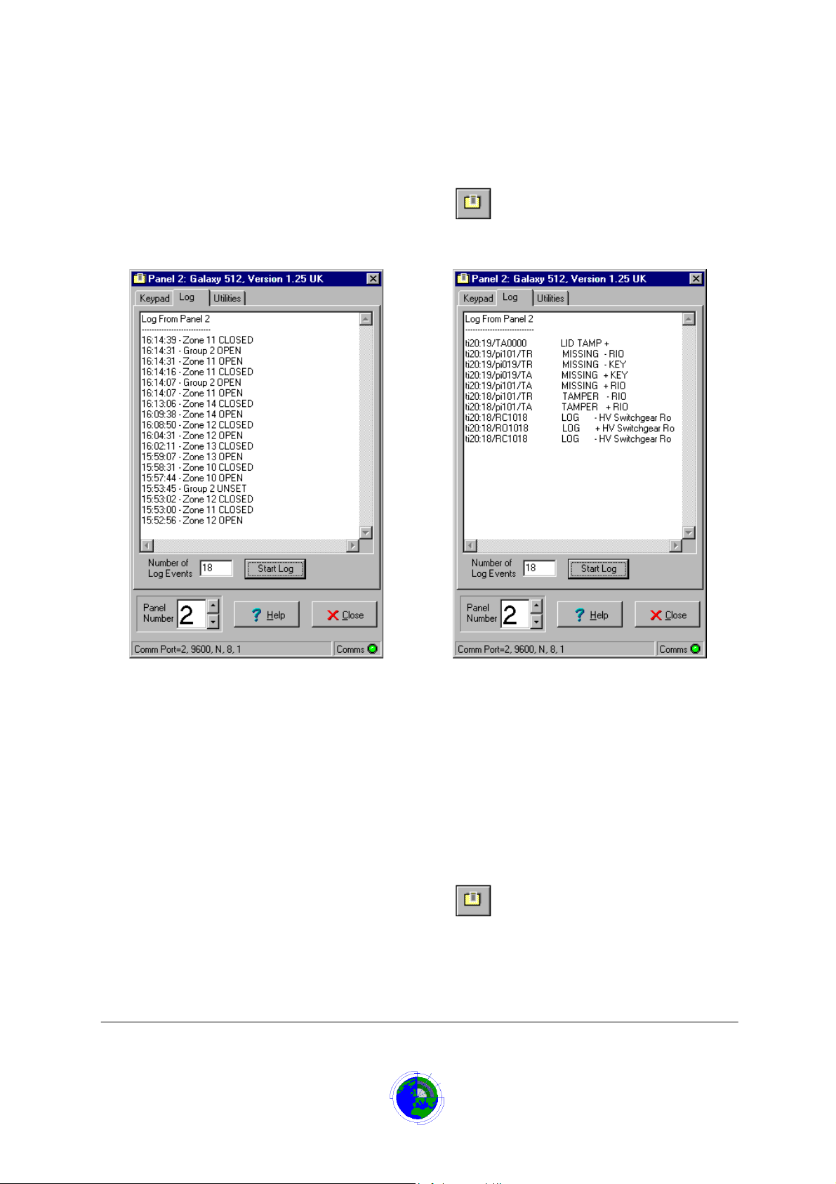
The Galaxy form will display, click the Log tab if the form is not as below
:
This option allows the Galaxy log events to be viewed as they are received by the Datalog system.
To display the log, ent er the number of events to display (maximum 100) in the Number of Log
Events then press the Start Log button. T he Log window will s tart d ispla ying log e vents as the y are
received, most rec ent at the top. W hen the num ber of events exceeds the ‘Num ber of Log ev ents’
the oldest will disappear from the bottom and be replaced with the latest at the top.
Utilities
An option is available, mainl y for eng ineering p urposes t o progr am panels , which will switc h output
relays and read the events log as it is transmitted to the Datalog. To use this option, sign on with an
appropriate password and cho ose ‘Galaxy’ from the ‘Tools’ m enu or press the speed button with
the Microtech panel/keypad lo go
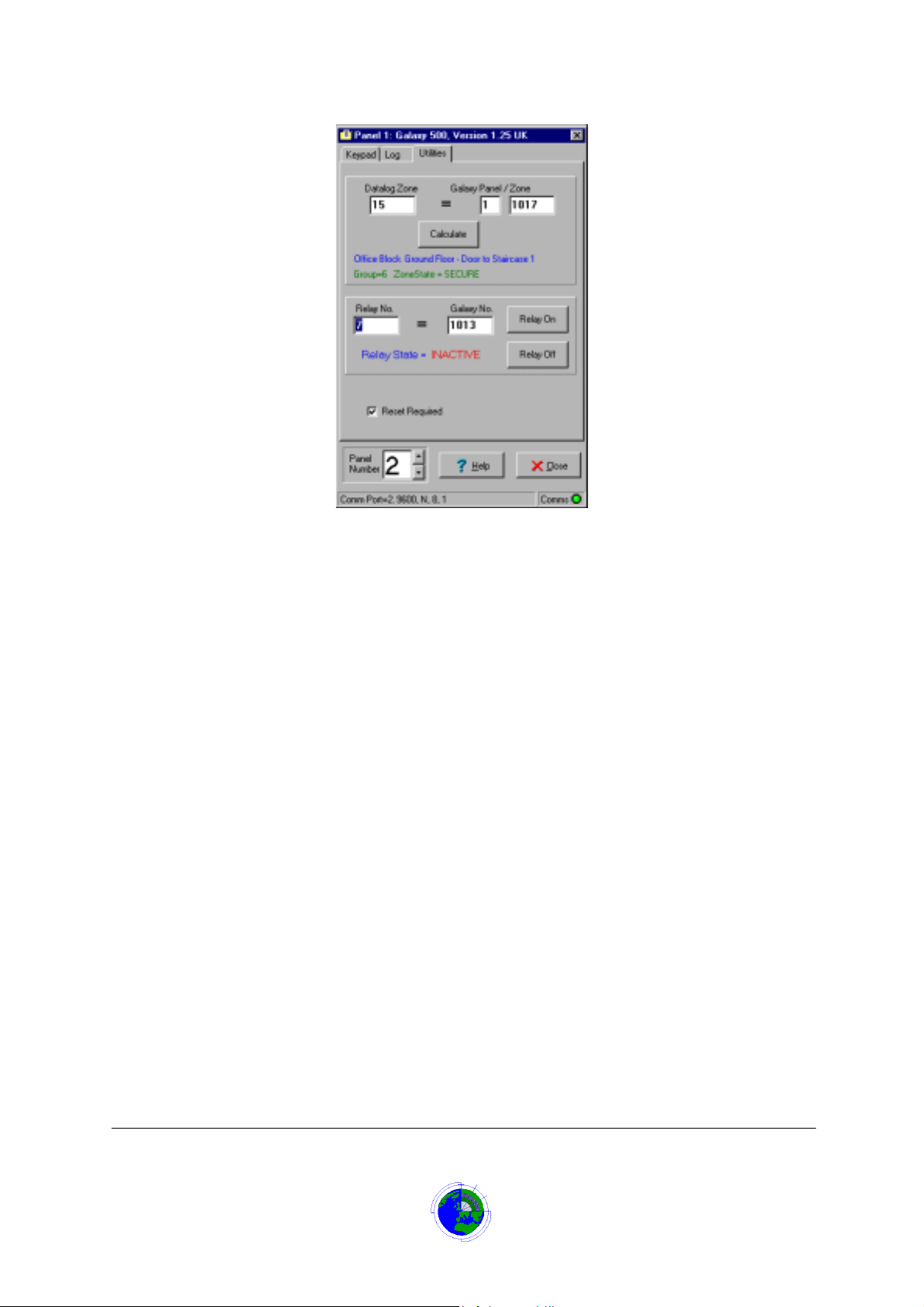
The Galaxy form will display, press the Utilities tab if the form is not as below:
.
/Cont’d
Microtech Galaxy 500/512 Panel
Page 6 of 8
CORTECH DEVELOPMENTS LTD
Page 7
Datalog 3 - SMS Software A pplicat ion Sheet
Panel Number Field
The panel number field is only visible if there is more than 1 Galaxy Panel connected to the
Datalog. Using the up /down buttons allows a differ ent panel to be selected. If using t he Remote
Keypad, viewing the event log or switching relays, the required panel must be selected first.
Datalog Zone
Entering a Datalog zone number in this field and clicking the calculate button, will display the
Galaxy panel number and equivalent Line/Module/Input Zone number in the Galaxy Panel and
Zone field as N LMMZ.
Galaxy Zone Field
The Galaxy Panel and Zone fields contains the panel zone number on the panel as N LMMZ
where N is the Panel n umber, L is the pane l line number , MM is the m odule num ber on that li ne,
and Z is the zone number on that module. Typing a relevant number and clicking the Calculate
button will display the equivalent Datalog zone number in the Datalog Zone field
.
Calculate Button
If a Datalog zone number has been entere d in the Datalog Zone field then cl icking the calculate
button, will display the Galaxy panel num ber and e quivalent L ine/Modu le/Input Z one num ber in th e
Galaxy Panel and Zone field as N LMMZ.
Alternatively if the Galaxy Panel and Zone fields contains the pan el zo ne number on the panel as N
LMMZ where N is the Panel num ber, L is t he p anel line number, MM is the m odule n um ber on that
line, and Z is the zone number on that module, then c licking the Calculate butt on will display the
equivalent Datalog zone number in the Datalog Zone field.
Zone Information
Entering a Datalog zone or Galax y panel and zone num ber then clicking the calc ulate button, will
display data about the zone. The line of data in blue text is the Da talog description for th at zone.
The line of text below the descriptio n will sho w the Pane l gro up to which th e zon e belo ngs, a nd th e
urrent state of that zone on the Datalog system.
Microtech Galaxy 500/512 Panel
Page 7 of 8
CORTECH DEVELOPMENTS LTD
Page 8

Datalog 3 - SMS Software A pplicat ion Sheet
Relay Number Field
The Relay No. field allows a relay number (1-256) to be entered.
On tabbing out of the field:
•
The Galaxy No. field will show the relay num ber on the panel as LMMR where L is the
panel line num ber, MM is t he m odule number on that lin e, an d R is the re la y num ber on
that module.
•
The system will check the relay state and display in the ‘State= ‘ field below.
•
Pressing the Relay On or Relay Off buttons will switch that relay.
Galaxy No. Field
The Galaxy No. field contains the r elay number on the panel as LMMR where L is the pane l line
number, MM is the module number on that line, and R is the rela y number on that m odule. T yping
a relevant number and tabbing out of this field will cause the Relay No. field to change to the
equivalent number, and the Relay state= XX will show the state of that relay according to the panel.
Pressing the Relay On or Relay Off buttons will cause the relay to set or reset on the panel.
Relay On Button
If the relay Number field contains a valid r elay number (1-256), pres sing the Relay On bu tton will
energise that relay.
Relay Off Button
If the relay Number field contains a valid r elay number (1-256), pres sing the Relay Off button will
de-energise that relay.
Panel Reset Required
If the Panel Reset Re quire d c hec k box is ticked then the system will sen d a r ese t back to the pa ne l
when a Datalog alarm reset (F2 Key pressed) is initiated.
Troubleshooting
No Communications
•
Ensure the ca ble betwee n the PC and th e RS23 2 m odule is wir ed as per the i nstallat ion
section of this document, and that it is connected.
•
Check the RS232 module is connected on L ine 1 of the Galaxy panel and en d of line
resistors fitted .
•
Ensure that the RS232 module switches are set for correct baud rate/Data bits/stop
bits/Parity as per the installation section of this document.
•
Check that the correct Comm port is being used.
•
Ensure that Engineer opt ion 56=COMMUNIC ATIONS has been set. Se e the installat ion
section of this document.
Communications but No Alarms On Remote Panel
•
Check that the panel address has been set using Engineer option
56=COMMUNICATIONS has been set. See the installation section of this document.
Panel 1 is 000001, Panel 2 is 000002 etc
•
Ensure the Alarm trigger(s) have been set to on using Engineer option
56=COMMUNICATIONS
Microtech Galaxy 500/512 Panel
Page 8 of 8
CORTECH DEVELOPMENTS LTD
 Loading...