

Page 1
C111 multImode
C111
DECAY / RELEASE
MULTIMODE CONTOUR GENERATOR
ATTACK
AD
ASR
LOOP
OFF
A
DECAY / RELEASE
ATTACK
AD
ASR
LOOP
OFF
B
DECAY / RELEASE
ATTACK
AD
ASR
LOOP
OFF
C
DECAY / RELEASE
ATTACK
AD
ASR
LOOP
OFF
D
GATE A
GATE B
OUT A
OUT B
A+B OUT
C+D OUT
GATE C
GATE D
OUT C
OUT D
BALANCE
BALANCE
CONTOUR GENERATOR
MIN MAX
MIN MAX
MIN MAX
MIN MAX
MIN MAX
A B
MIN MAX
MIN MAX
C D
MIN MAX
USER MANUAL
Page 2
c111 MULTIMODE CONTOUR GENERATOR
C111
DECAY / RELEASE
MULTIMODE CONTOUR GENERATOR
ATTACK
AD
ASR
LOOP
OFF
A
DECAY / RELEASE
ATTACK
AD
ASR
LOOP
OFF
B
DECAY / RELEASE
ATTACK
AD
ASR
LOOP
OFF
C
DECAY / RELEASE
ATTACK
AD
ASR
LOOP
OFF
D
GATE A
GATE B
OUT A
OUT B
A+B OUT
C+D OUT
GATE C
GATE D
OUT C
OUT D
BALANCE
BALANCE
C111 MULTIMODE
CONTOUR GENERATOR
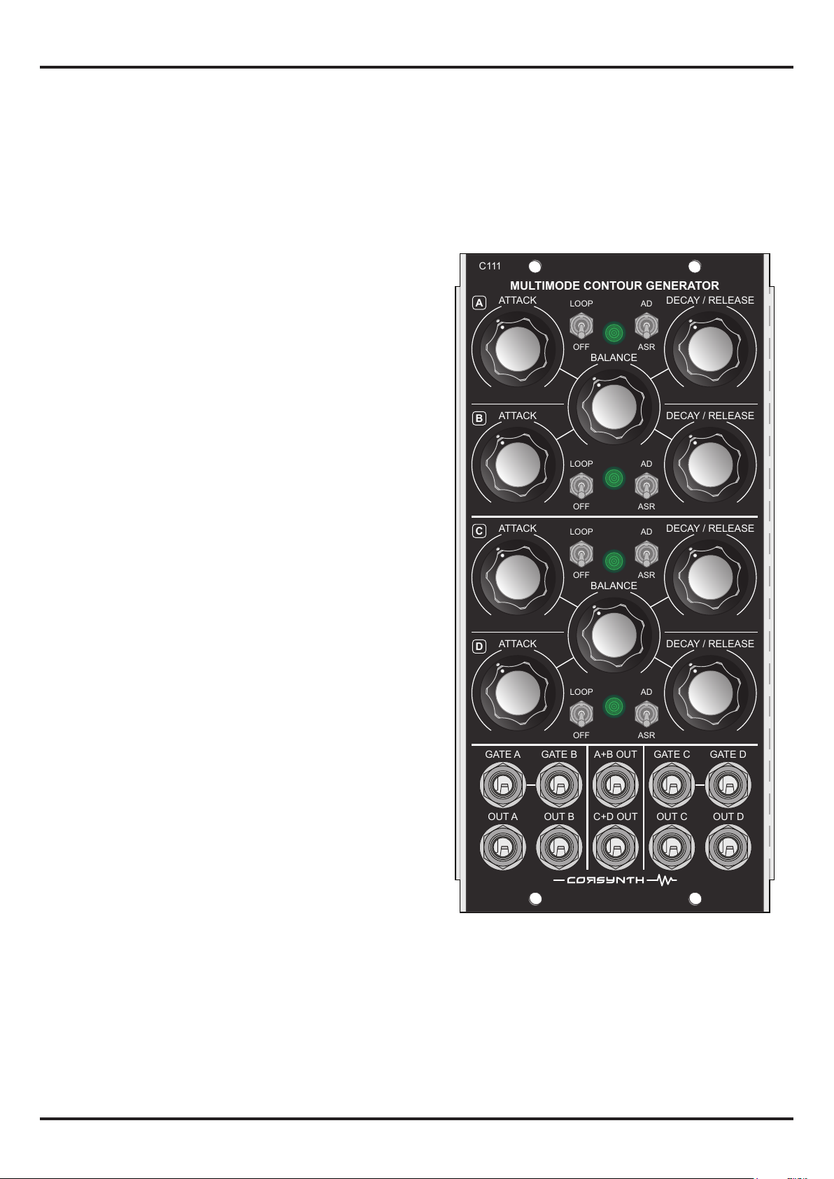
The C111 Multimode Contour Generator is a quad
analogue envelope generator and modulation source. It
can be congured to create dierent kind of envelopes,
from AD to ADSR and many more.
The module is composed by four identical envelopes with
two operation modes :
- AD : Attack - Decay
- ASR : Attack - Sustain - Release
MIN MAX
MIN MAX
A B
These envelopes can be combined by pairs to create
envelope shapes that are not possible using a regular
envelope generator. Up to six dierent envelopes are
available at the same time.
Other important feature is that each envelope can be set in
loop mode.This opens the possibility to use the envelopes
as a LFO. The frequency range goes from 60Hz to one cycle
every 15 seconds. It’s also possible to combine two
envelopes in loop mode to generate complex modulation
signals.
C111 main characteristics :
- Four independent envelopes with AD and ASR modes
- Each envelope can be set in Loop mode independently
- Attack time from 1mS to 5 seconds
- Decay time from 20 mS to 10 seconds
- Gate A-B and Gate C-D are internally connected
- Up to six envelopes available at the same time.
MIN MAX
MIN MAX
MIN MAX
MIN MAX
MIN MAX
C D
MIN MAX
All this features make the C111 Multimode Contour
Generator a really versatile module that can be used in
every patch in your system.
HTTP://WWW.CORSYNTH.COM
1
Page 3
c111 multImode CONTOUR GENERATOR
C111
DECAY / RELEASE
MULTIMODE CONTOUR GENERATOR
ATTACK
AD
ASR
LOOP
OFF
A
DECAY / RELEASE
ATTACK
AD
ASR
LOOP
OFF
B
DECAY / RELEASE
ATTACK
AD
ASR
LOOP
OFF
C
DECAY / RELEASE
ATTACK
AD
ASR
LOOP
OFF
D
GATE A
GATE B
OUT A
OUT B
A+B OUT
C+D OUT
GATE C
GATE D
OUT C
OUT D
BALANCE
BALANCE
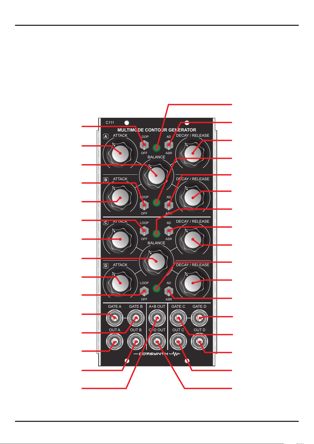
C111 Multimode Contour Generator
Front Panel
Env A - Output LED
Env A - Loop On / O
Env A - Attack time
Env A / B - Balance
Env B - Loop On / O
Env B - Attack time
Env C - Loop On / O
Env C - Attack time
Env C / D - Balance
MIN MAX
MIN MAX
MIN MAX
A B
MIN MAX
MIN MAX
MIN MAX
Env A mode - AD / ASR
Env A - Decay / Release
time
Env B - Output LED
Env B mode - AD / ASR
Env B - Decay / Release
time
Env C - Output LED
Env C mode - AD / ASR
Env C - Decay / Release
time
Env D - Output LED
Env D - Attack time
Env D - Loop On / O
MIN MAX
Evn A - Gate input
Evn B - Gate input
Env A - Out
Env B - Out
Env A+B - Out
HTTP://WWW.CORSYNTH.COM
C D
MIN MAX
Env D - Decay / Release
time
Env D mode - AD / ASR
Env D - Gate input
Env C - Gate input
Env D - Out
Env C - Out
Env C+D - Out
2
Page 4
c111 multImode CONTOUR GENERATOR
ATTACK
DECAY / RELEASE
LOOP
OFF
AD
ASR
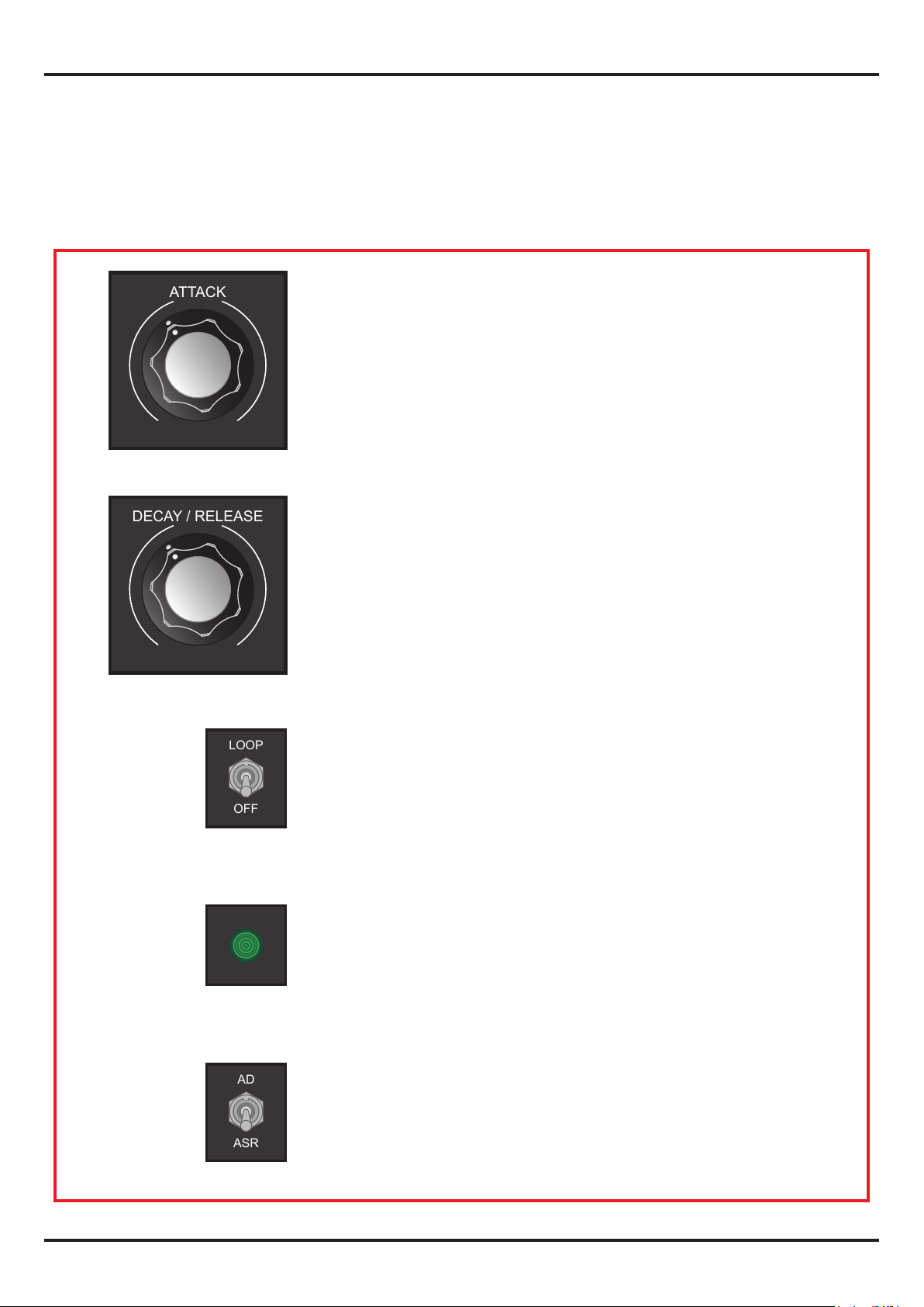
CONTROL DESCRIPTION
These controls have the same funtion in the A,B,C and D sections
AT TAC K
This control sets the Attack Time of the envelope. Attack times
goes from 1 milliseconds up to 5 seconds.
MIN MAX
MIN MAX
DECAY / RELEASE
This potentiometer sets the Decay / Release Time of the envelo-
pe. Decay / Release times goes from 15 milliseconds up to 10
seconds.
ENVELOPE LOOP ON/OFF SWITCH
LOOP: After reach the end of the Decay / Release phase the
envelope restarts automatically.
OFF: After reach the end of the Decay / Release phase the enve-
lope remains at 0V until another trigger/gate signal is received.
OUTPUT LED
LED brightness follows the envelope output.
HTTP://WWW.CORSYNTH.COM
ENVELOPE MODE SWITCH
This switch selects de envelope mode of operation.
AD: Attack - Decay mode
ASR: Attack - Sustain - Release mode
Operation modes are explained in detail in page 6.
3
Page 5
BALANCE
A B
BALANCE
GATE A
OUT B
OUT A
GATE B
C D
c111 multImode CONTOUR GENERATOR
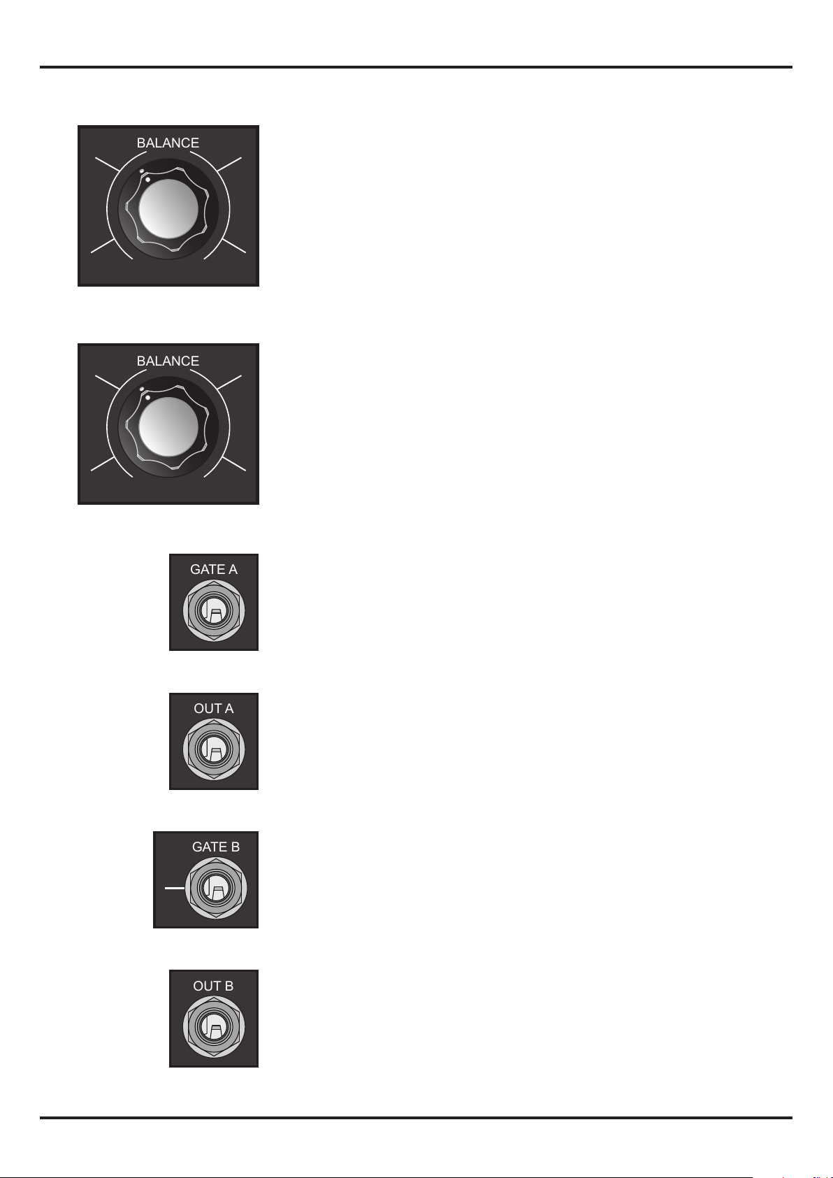
BALANCE ( A / B )
This potentiometer sets the balance between Envelope A and B
at the A+B output.
A : only Envelope A
B : only Envelope B
Middle : same amount of Envelope A and B
BALANCE ( C / D )
This potentiometer sets the balance between Envelope C and D
at the C+D output.
C : only Envelope C
D : only Envelope D
Middle : same amount of Envelope C and D
GATE A
Envelope A gate / trigger input. The gate / trigger signal should
have a positive voltage higher that 2.5V.
OUT A
Envelope A output.
GATE B
Envelope B gate / trigger input. The gate / trigger signal should
have a positive voltage higher that 2.5V. The Gate B input is internally connected to the Gate A input. This connection breaks
when a jack is inserted.
HTTP://WWW.CORSYNTH.COM
OUT B
Envelope B output.
4
Page 6
c111 multImode CONTOUR GENERATOR
GATE C
OUT D
OUT C
GATE D
A+B OUT
C+D OUT
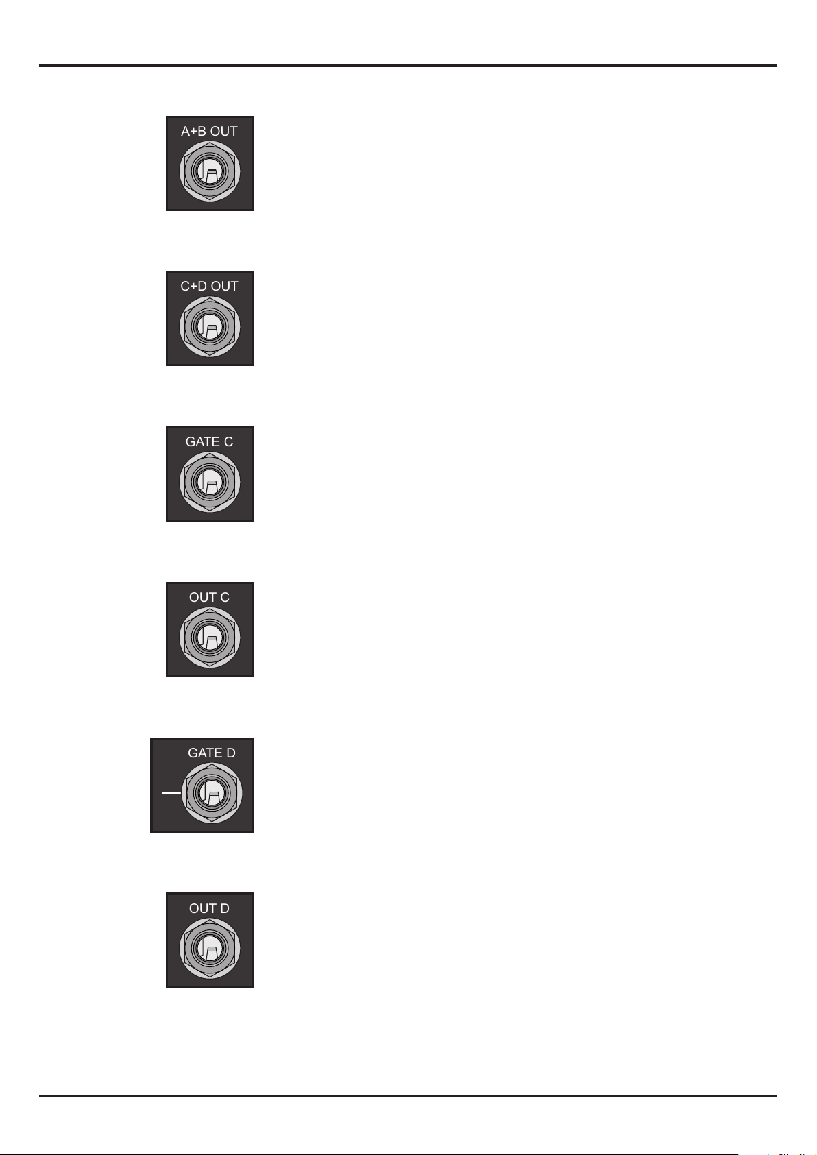
A+B OUT
Envelope A+B output.
C+D OUT
Envelope C+D output.
GATE C
Envelope C gate / trigger input. The gate / trigger signal should
have a positive voltage higher that 2.5V.
OUT C
Envelope C output.
GATE D
Envelope D gate / trigger input. The gate / trigger signal should
have a positive voltage higher that 2.5V. The Gate D input is internally connected to the Gate C input. This connection breaks
when a jack is inserted.
OUT D
Envelope D output.
HTTP://WWW.CORSYNTH.COM
5
Page 7
c111 multImode CONTOUR GENERATOR
Operation Modes
All four envelopes in the module have two basic operation modes selectable by one switch in the front
panel. This two modes are AD ( Attack / Decay ) and ASR ( Attack / Sustain / release ). The envelope will
behave dierent depending witch operation mode is selected.
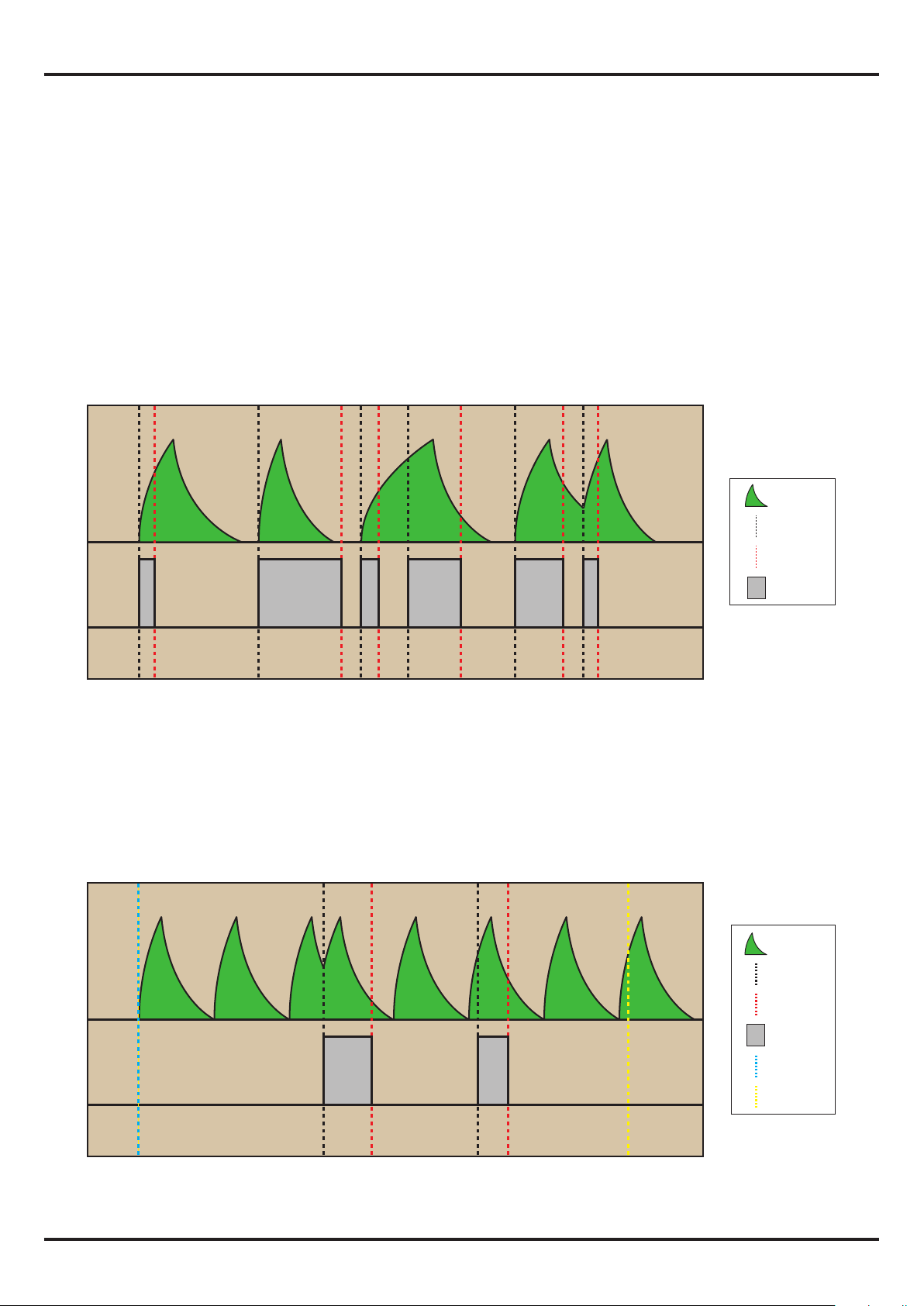
AD
In this mode the gate length is irrelevant. Once the gate signal is received the envelope will raise until
reach 5V and then will start to fall to 0V. In this mode the envelope can be re-triggered at any moment
of the Decay phase but if a gate signal is received during the Attack phase it will be ignored.
AD
Envelope
Gate ON
Gate OFF
Gate signal
Gate
Envelope in AD mode , loop OFF
When the loop switch is activated the envelope will start to cycle between the attack and decay phase
without the need of a gate signal. The envelope can be re-triggered at any moment of the Decay phase
but if a gate signal is received during the Attack phase it will be ignored. If the loop mode is disconnected during the Attack or Decay phase, the envelope will complete its full cycle and it will remain at 0V
until a new gate is received or the loop mode is activated.
AD
Loop ON
Envelope
Gate ON
Gate
Envelope in AD mode , loop ON
HTTP://WWW.CORSYNTH.COM
Gate OFF
Gate signal
Loop ON
Loop OFF
6
Page 8
c111 multImode CONTOUR GENERATOR
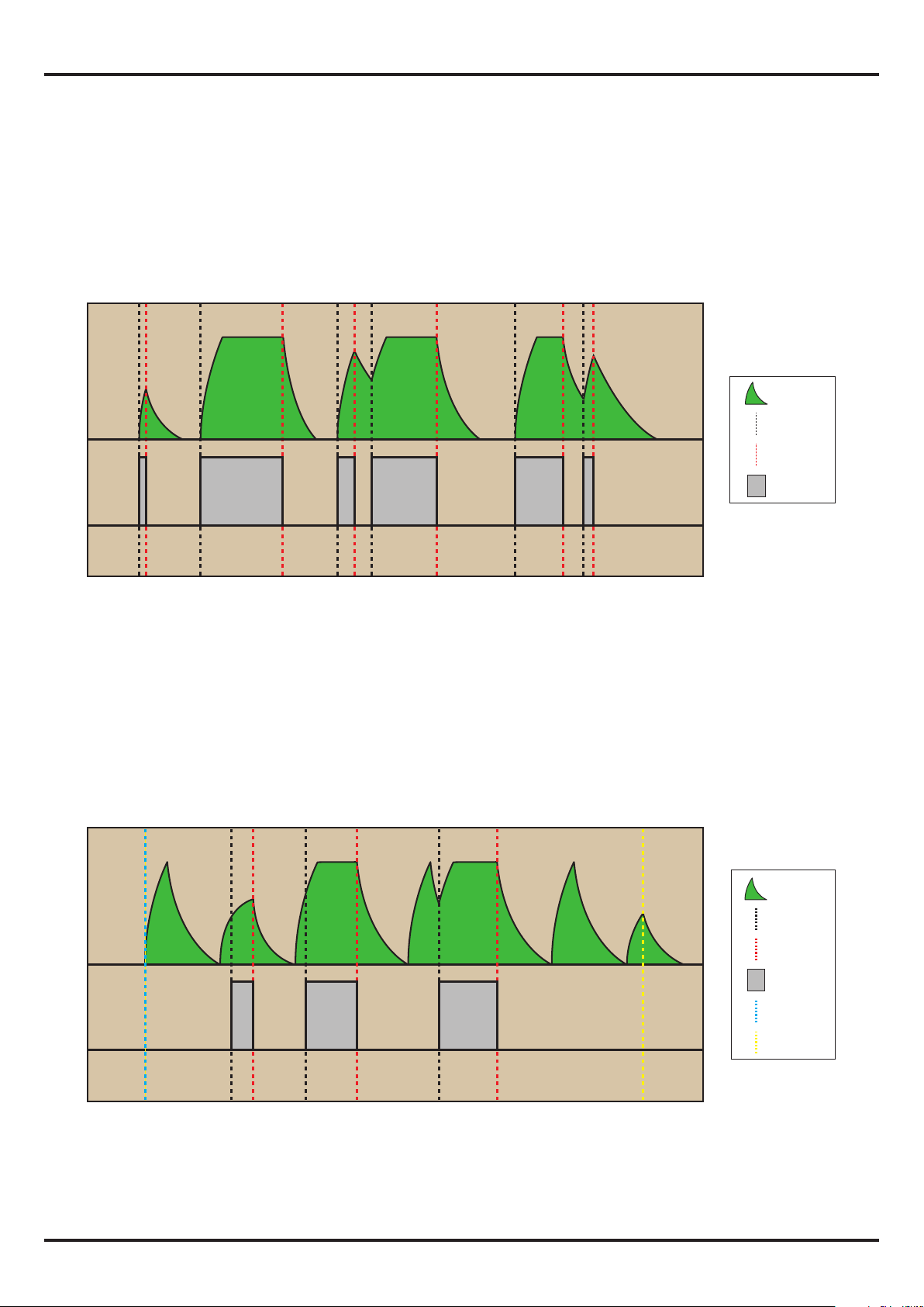
ASR
In this mode when a gate signal is received the envelope will raise until reach 5V and it will remain at
that level as long as the gate signal is active. After that, the envelope will start to fall to 0V. In case the
gate length is shorter than the Attack time, the envelope will start to fall to 0V as soon as the gate is
removed. In ASR mode the envelope can be re-triggered at any moment of the Decay phase.
ASR
Envelope
Gate ON
Gate OFF
Gate signal
Gate
Envelope in ASR mode , loop OFF
When the loop switch is activated the envelope will start to cycle between the attack and decay phase
without the need of a gate signal. In case a gate signal is received during the Attack phase, the envelope
will raise until reach 5V and it will remain at that level as long as the gate signal is active. In case the gate
length is shorter than the Attack time, the envelope will start to fall to 0V as soon as the gate is removed.
The envelope can be re-triggered at any moment of the Decay phase. If the loop mode is disconnected,
the envelope will start to fall to 0V it will remain at that level until a new gate is received or the loop
mode is activated.
ASR
Loop OFF
Envelope
Gate ON
Gate OFF
Gate
Envelope in ASR mode , loop ON
HTTP://WWW.CORSYNTH.COM
Gate signal
Loop ON
Loop OFF
7
Page 9
c111 multImode CONTOUR GENERATOR
DECAY / RELEASE
ATTACK
AD
ASR
LOOP
OFF
A
DECAY / RELEASE
ATTACK
AD
ASR
LOOP
OFF
B
BALANCE
DECAY / RELEASE
ATTACK
AD
ASR
LOOP
OFF
A
DECAY / RELEASE
ATTACK
AD
ASR
LOOP
OFF
B
BALANCE
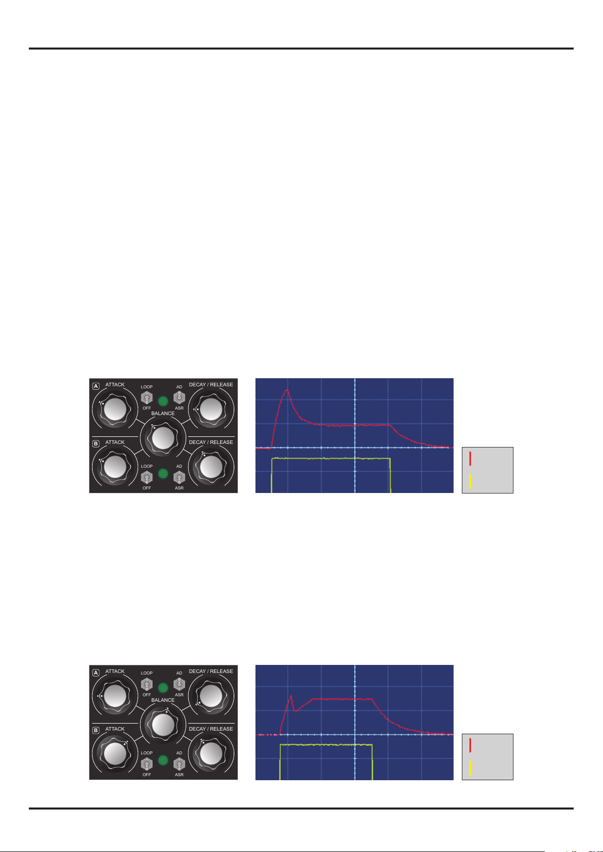
USING THE MIX OUTPUTS ( A+B , C+D)
One of the more interesting features of the C111 is the possibility to combine two envelopes to
create new envelope shapes. Using the A+B and C+D outputs is easy to obtain envelopes not possible using a normal envelope generator. This section explain how to set up the module to create those
kind of envelopes. The knobs in the examples, are set to obtain the envelope times shown in the
graphics. Shorter or longer times are possible for every kind of envelope. Since these envelopes are
obtained adding and subtracting signals, some of them will not reach the typical 5V peak. The
graphic resolutions are, vertical 2 volts/division and horizontal 1 second/division.
ADSR ( Attack - Decay - Sustain - Release )
The more typical synthesizer envelope. To obtain an ADSR, one envelope has to be set to AD and the
other to ASR. Attack times should be the same in both envelopes. The Decay time is determined by
the AD envelope and the release time by the ASR envelope. The BALANCE knob sets the Sustain level,
the more ASR envelope ( in this case B ) the sustain level will be higher. The only dierence with a
normal ADSR is that in case the gate signal is removed before the end of the attack phase , the AD
envelope will complete anyway its full cycle .
MIN MAX
A B
MIN MAX
MIN MAX
MIN MAX
Envelope
Gate
ADASR ( Attack - Decay - Attack - Sustain - Release )
This is a variation of the ADSR envelope. It has an Attack-Decay phase followed by a second Attack
until reach the Sustain level. As before one envelope has to be set to AD and the other to ASR. The
Attack and Decay time of the AD envelope should be short, especially the Decay time. In total the AD
envelope has to be shorter than the Attack time of the ASR envelope. The BALANCE knob sets the
Sustain level but it also aects the Attack phase, with more ASR envelope the rst Attack-Decay
phase will be less accentuated.
MIN MAX
MIN MAX
HTTP://WWW.CORSYNTH.COM
MIN MAX
A B
MIN MAX
Envelope
Gate
8
Page 10
c111 multImode CONTOUR GENERATOR
DECAY / RELEASE
ATTACK
AD
ASR
LOOP
OFF
A
DECAY / RELEASE
ATTACK
AD
ASR
LOOP
OFF
B
BALANCE
DECAY / RELEASE
ATTACK
AD
ASR
LOOP
OFF
A
DECAY / RELEASE
ATTACK
AD
ASR
LOOP
OFF
B
BALANCE
DECAY / RELEASE
ATTACK
AD
ASR
LOOP
OFF
A
DECAY / RELEASE
ATTACK
AD
ASR
LOOP
OFF
B
BALANCE
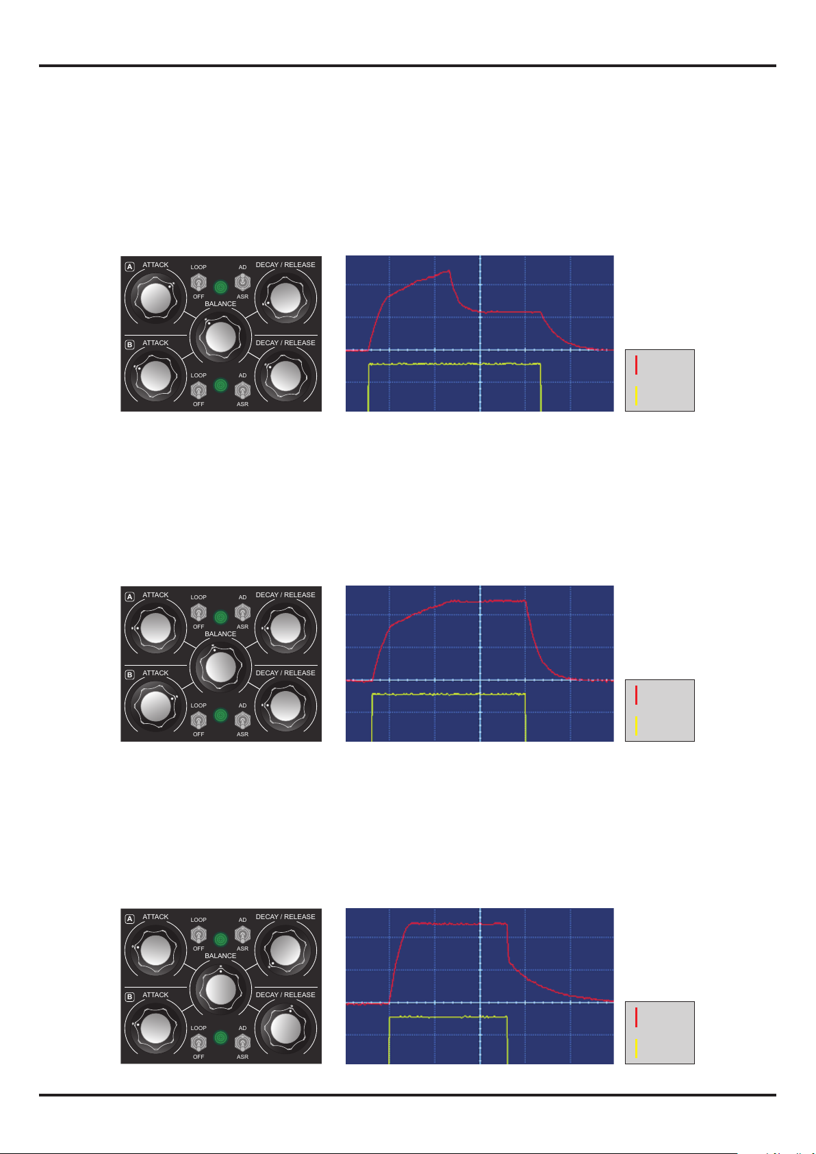
AADSR ( Attack - Attack - Decay - Sustain - Release )
This is another ADSR variation. This envelope has two Attack sections, the rst one faster than the
second one. As in the previous examples, one envelope has to be set to AD and the other to ASR. To
obtain the two attack phases, the Attack of the AD envelope has to be longer than the Attack time of
the ASR envelope. The Decay time is determined by the AD envelope and the release time by the ASR
envelope. The BALANCE knob sets the Sustain level, the more ASR the higher will be the sustain.It
also sets the break point of the two Attack phases.
MIN
MIN MAX
MAX
A B
MIN MAX
MIN MAX
Envelope
Gate
AASR ( Attack - Attack - Sustain - Release )
This envelope has two Attack sections, the rst one faster than the second one, followed by a sustain
and release sections. To obtain this kind of shape both envelopes have to be set to ASR and they must
have dierent Attack times and the same Release times. The BALANCE knob sets the break point of
the two Attack phases.
MAX
MIN
A B
MAX
MIN
Envelope
MIN MAX
MIN MAX
Gate
ASRR ( Attack - Sustain - Release - Release )
This envelope has an Attack and Sustain phases followed by a two Release sections with the rst one
faster than the second one. To obtain this kind of shape both envelopes have to be set to ASR and
they must have the same Attack times and the dierent Release times. The BALANCE knob sets the
break point of the two Release phases.
MAX
MIN
A B
MIN MAX
HTTP://WWW.CORSYNTH.COM
MIN MAX
MIN MAX
Envelope
Gate
9
Page 11
c111 multImode CONTOUR GENERATOR
DECAY / RELEASE
ATTACK
AD
ASR
LOOP
OFF
A
DECAY / RELEASE
ATTACK
AD
ASR
LOOP
OFF
B
BALANCE
DECAY / RELEASE
ATTACK
AD
ASR
LOOP
OFF
A
DECAY / RELEASE
ATTACK
AD
ASR
LOOP
OFF
B
BALANCE
DECAY / RELEASE
ATTACK
AD
ASR
LOOP
OFF
A
DECAY / RELEASE
ATTACK
AD
ASR
LOOP
OFF
B
BALANCE
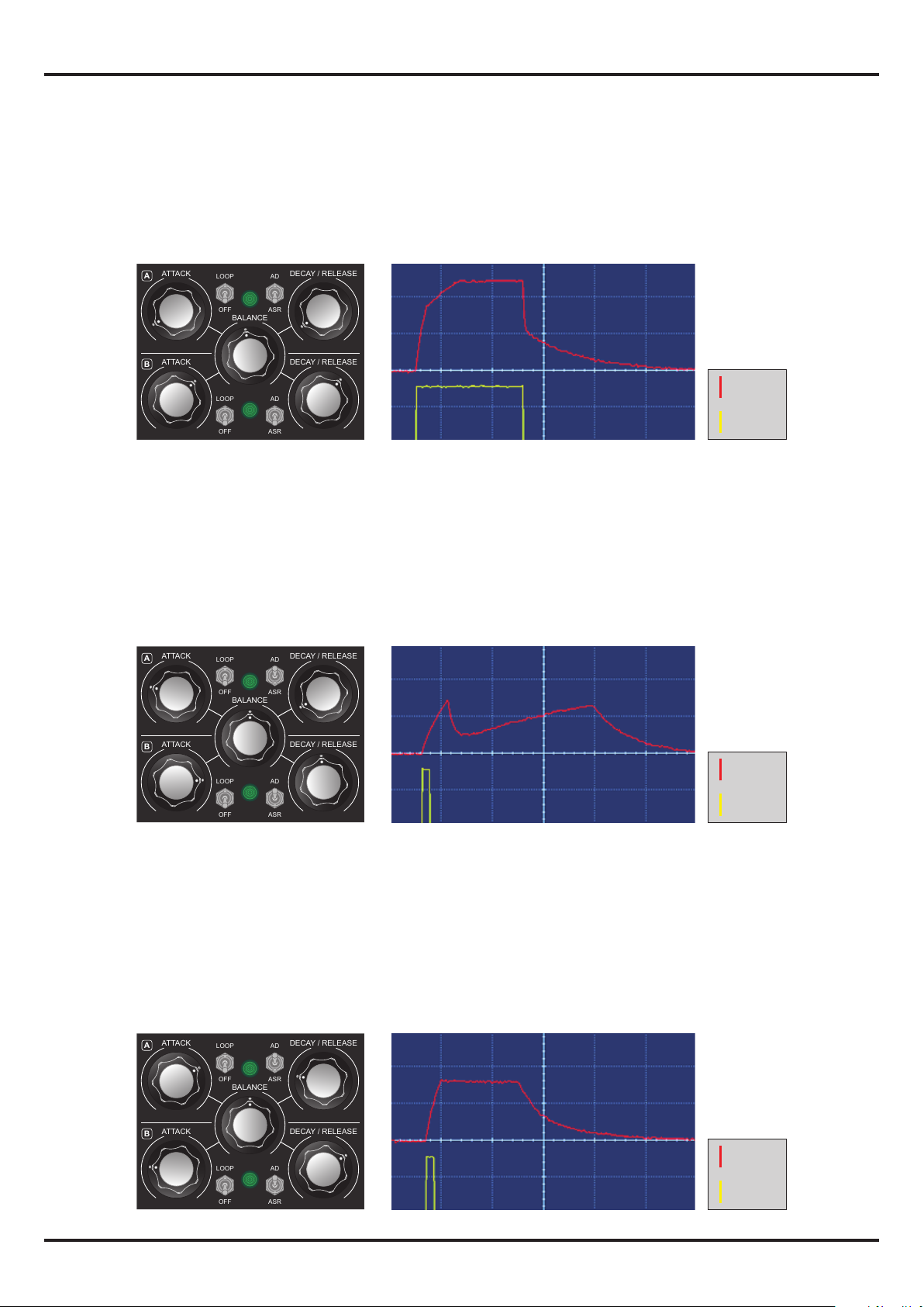
AASRR ( Attack - Attack - Sustain - Release - Release )
This envelope has two Attack sections followed by Sustain phase and two Release sections. The rst
Attack and Release sections are faster than the second ones. To obtain this kind of shape both envelopes must be set to ASR and they must have dierent Attack and Release times. The BALANCE knob
sets the break point for the Attack and Release phases.
MIN MAX
A B
MIN MAX
MIN MAX
MIN MAX
Envelope
Gate
ADD ( Attack - Decay - Attack - Decay )
This envelope is a combination of two AD envelopes. The Attack and Decay time of rst AD envelope
should be shorter than the Attack time of second AD envelope. The BALANCE sets the amount of
each envelope present in the nal envelope. Since they are both AD envelopes the gate length is not
important.
MAX
MIN
A B
MIN MAX
Envelope
MIN MAX
MIN MAX
Gate
ADD ( Attack - Hold - Decay )
This envelope has an Attack phase followed by a Hold time and a Decay phase. To obtain this shape
both envelopes must be in AD mode. The Attack time of the rst envelope must be equal to the
Release time of the second one. In the same way the Attack time of the second must be equal to the
Release time of the rst envelope. The BALANCE knob should be more or less in middle position .
MIN MAX
A B
MIN MAX
MIN MAX
MIN MAX
Envelope
Gate
HTTP://WWW.CORSYNTH.COM
10
Page 12
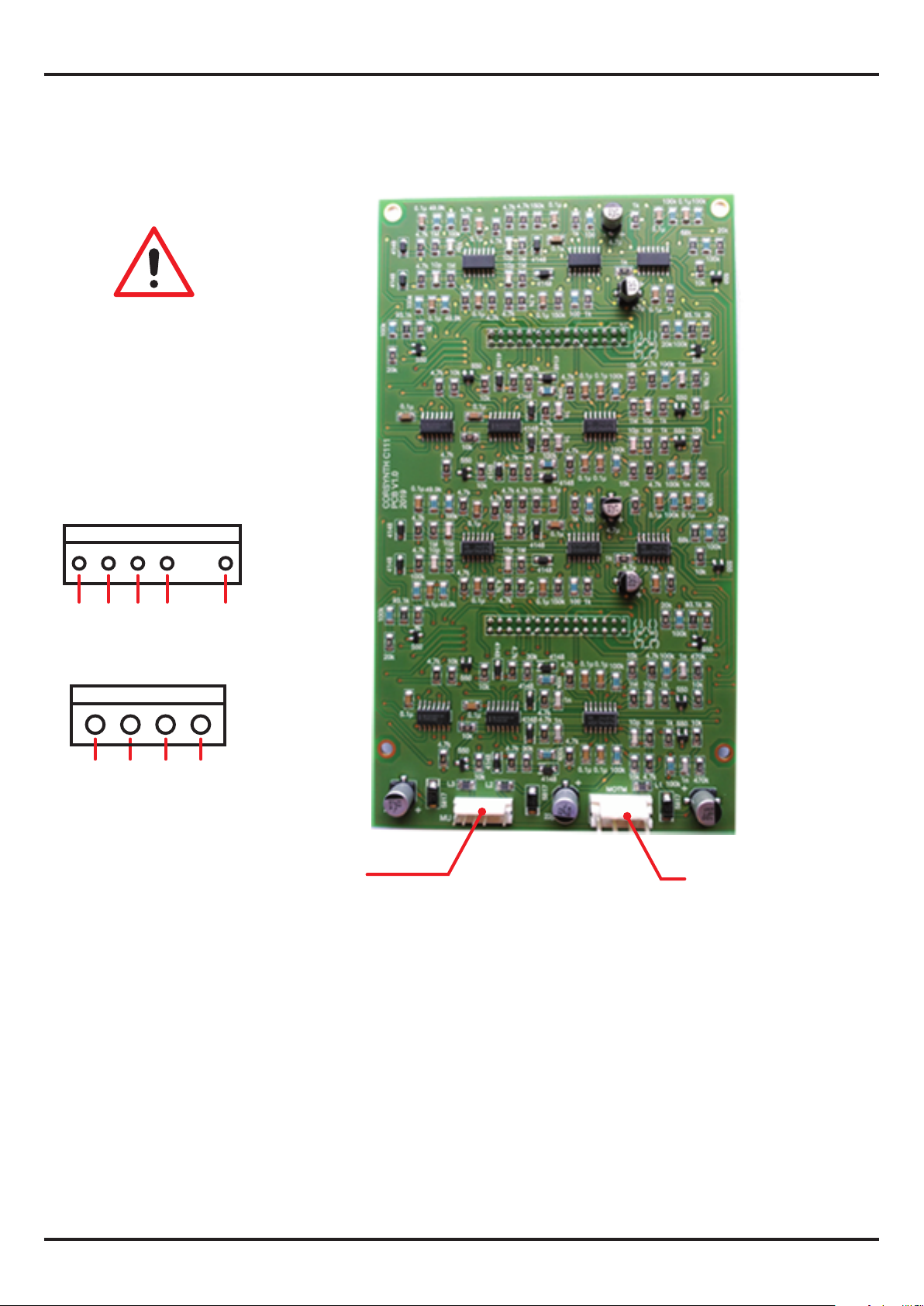
Trimmers and power connectors
IMPORTANT !!!!
This module has two power connectors
(MU and MOTM).
Only one is needed to power the
module. (MU or MOTM).
Never connect both at the
same time.
MU
c111 multImode CONTOUR GENERATOR
MOTM
GND +15V-15V
GND
+15V+5V-15VN/C GND
MU
power connector
TECHNICAL DATA
MOTM
power connector
Module Format : 5U, MU format ( Synthesizers.com, Moog )
Module Width : 2 MU ( Moog unit )
Module Depth : 52 mm ( 2,05 inches )
Power : +15V@65mA , -15V@64mA
Power connectors : MU, MOTM ( 4 pin )
HTTP://WWW.CORSYNTH.COM
11
Page 13
c111 multImode CONTOUR GENERATOR
MODULAR LEVEL
MIN MAX
MODULAR SYNTHS
HTTP://WWW.CORSYNTH.COM
12
 Loading...