

Page 1

corsair.com
TM
FACEBOOK: facebook.com/corsairmemory
© 2015 Corsair Components, Inc. All rights reserved. Corsair and the sails logo are registered trademarks, and Corsair is a trademark
in the United States and/or other countries. All other trademarks are the property of their respective owners. Product may vary slightly from those pictured.
EMAIL: support@corsair.com
BLOG: corsair.com/blog/
USA and CANADA: (510) 657-8747 | INTERNATIONAL: (888) 222-4346 | FAX: (510) 657-8748
47100 Bayside Parkway • Fremont • California • 94538 • USA
Document Number: 49-001430 rev AA
FORUM: forum.corsair.com
TWITTER: twitter.com/corsairmemory
H100i GTX PAGE: corsair.com/H100iGTX
QUICK START GUIDE
GUIDE DE DÉMARRAGE RAPIDE
SCHNELLSTARTANLEITUNG
GUÍA BREVE DE INICIO
КРАТКОЕ РУКОВОДСТВО
快速入门指南
H100i v2
EXTREME PERFORMANCE LIQUID CPU COOLER
Page 2
Note: Most newer PC cases include a CPU cutout to allow access to the bottom of
the motherboard. If your case does not include a cutout, you will need to remove
your motherboard from the case before installation.
Remarque : la plupart des nouveaux boîtiers de PC comportent un accès facilité au
processeur qui permet d'accéder à la base de la carte mère. Si aucun accès n'est
prévu sur votre boîtier, vous devrez retirer votre carte mère du boîtier avant de
procéder à l'installation.
Hinweis: Bei neueren PC-Gehäusen gibt in der Regel eine CPU-Önung Zugang zur
Unterseite der Hauptplatine. Falls Ihr Gehäuse keine derartige Önung aufweist,
müssen Sie vor der Installation die Hauptplatine ausbauen.
Nota: La mayoría de las carcasas de las nuevas PC incluyen una puerta trasera para el
CPU a fin de permitir el acceso a la parte inferior del motherboard. Si su carcasa no
tiene esta entrada, deberá retirar el motherboard de la carcasa antes de la instalación.
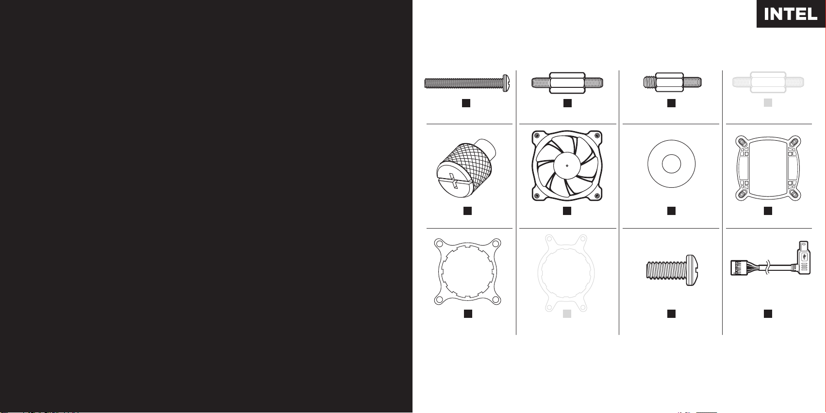
Included Hardware
Highlighted parts for Intel installation only • Les sections en surbrillance concernent
uniquement l'installation Intel • Die markierten Passagen beziehen sich nur auf die Intel
Componentes de instalación solamente para Intel • Части, выделенные цветом, только для у
становки Intel • 突出显示的部分仅限Intel安装
x8 LONG FAN SCREWS
A
x4 LGA 115X / 1366 STANDOFF
B
x4 LGA 2011 STANDOFF
C
x4 AMD BLACK STANDOFF
D
Примечание. На большинстве современных корпусов ПК имеется прорезь для предоставления
доступа к нижней части материнской платы. Если на вашем корпусе нет такой прорези, то перед
установкой необходимо удалить материнскую плату из корпуса.
注:大部分型号较新的PC机箱都配有CPU散热器更换口,可以在不移动主板的情况直接更换CPU散热器
,如果您的机箱未预留此空间,需要在水冷安装前取下主板。
E
x4 THUMBSCREWS
x1 INTEL MOUNTING BRACKET
Note: The H100i v2 comes with Intel mounting bracket pre-installed on the pump for quick installation.
Remarque : pour une installation plus rapide, le support de fixation Intel est déjà monté sur la pompe du dissipateur H100i v2.
Hinweis: Beim Hochleistungsprozessorkühler H100i v2 ist die Intel-Montagehalterung bereits auf der Pumpe vorinstalliert und
ermöglicht so eine besonders schnelle Montage.
Nota: El H100i v2 viene con un soporte de montaje Intel preinstalado en la bomba para una instalación rápida.
Примечание. H100i v2 поставляется с установленным на насос монтажным кронштейном Intel для быстрой установки.
注:H100i v2的泵机上预装了Intel安装支架,可进行快速安装。
I
(PRE-INSTALLED)
F
x2 SP120L FANS
J
x1 AMD MOUNTING
BRACKET
G
x16 WASHER
K
x8 SHORT SCREWS
x1 INTEL BACKPLATE
CORSAIR LINK USB CABLE
H
L
(Included)
Page 3

1
Installing the Intel Backplate
Installation de la plaque arrière Intel • Installation der Intel-Rückwand
Instalación de la placa de soporte para Intel • Установка опорной пластины Intel
安装Intel背板
LGA 1366
• For LGA 115X installation, slide the backplate
pins inside (figure 1).
• For LGA 1366 installation, slide the backplate
pins outside (figure 1).
• Install the assembled backplate (figure 2).
Note: Intel LGA 2011 does not require backplate
installation. Proceed to step 2.
• Pour l'installation sur un socket LGA 115x, faites glisser
les broches de la plaque arrière vers l'intérieur (figure 1).
• Pour l'installation sur un socket LGA 1366, faites glisser
les broches de la plaque arrière vers l'extérieur (figure 1).
• Installez la plaque arrière assemblée (figure 2).
Remarque: Le socket Intel LGA 2011 ne requiert pas
l'installation d'une plaque arrière. Passez à l'étape 2.
• Schieben Sie die Stifte der Rückwand nach innen,
um LGA 115X zu montieren (Abbildung 1).
• Schieben Sie die Stifte der Rückwand nach innen,
um LGA 1366 zu montieren (Abbildung 1).
• Montieren Sie die zusammengebaute Rückwand
(Abbildung 2).
Hinweis: Für den Intel LGA 2011 ist keine Rückwand
erforderlich. Fahren Sie mit Schritt 2 fort.
• Para instalación en LGA 115X, deslice la placa de soporte
con las patillas hacia dentro (figura 1).
• Para instalación en LGA 1366, deslice la placa de soporte
con las patillas hacia fuera (figura 1).
• Instale la placa de soporte ensamblada (figura 2).
Nota: Intel LGA 2011 no requiere que se instale
una placa de soporte. Siga con el paso 2.
• При установке LGA 115X задвиньте штырьки
внутрь (Рис. 1).
• При установке LGA 1366 задвиньте штырьки
наружу (Рис. 1).
• Установите собранную опорную пластину. (Рис. 2)
Примечание. Для Intel LGA 2011 установка опорной
пластины не требуется. Перейдите к шагу 2.
• 要安装LGA 115X,请将背板针脚插入(图1)。
• 要安装LGA 1366,请将背板针脚拔出(图1)。
• 安装组装好的背板(图2)。
注:Intel LGA 2011不需要安装背板。继续执行步骤2。
LGA
115X
figure 1
figure 2
Page 4

2
Installing the Intel Stando Screws
Installation des vis d'entretoise Intel • Installation der Intel-Abstandhalter
3
Instalación de los tornillos del separador para Intel • Установка опорных винтов Intel
安装Intel隔架螺丝
LGA 115X/1366
LGA2011
B
C
• Attach the provided Intel stando.
• Use (B) for LGA 115X / 1366, or (C)
for LGA 2011.
• Tighten all four screws until firmly secure.
• Fixez les entretoises Intel fournies.
• Utilisez-en (B) pour un socket LGA 115X / 1366
ou (C) pour un socket LGA 2011.
• Serrez les quatre vis jusqu'à ce qu'elles ne
puissent plus bouger.
• Befestigen Sie den im Lieferumfang
enthaltenen Intel-Abstandhalter.
• Verwenden Sie (B) für LGA 115X / 1366
oder (C) für LGA 2011.
• Ziehen Sie alle vier Schrauben fest.
• Conecte el separador para Intel suministrado.
• Utilice (B) para LGA 115X / 1366 o (C) para
LGA 2011.
• Apriete los cuatro tornillos hasta que estén
bien fijados.
• Прикрепите входящую в комплект опору
Intel.
• Для LGA 115X / 1366 используйте (B), а для
LGA 2011— (C).
• Хорошо затяните все четыре винта.
• 连接随附的Intel隔架。
• 为LGA 115X / 1366使用(B),或者为LGA 2011使
用(C)。
• 拧紧全部四个螺丝,直至牢牢地固定。
Install the Fans and Radiator
Installation des ventilateurs et du radiateur • Lüfter und Kühler einbauen
Instale los ventiladores y el radiador • Установка вентиляторов и радиатора
安装风扇和散热器
Attach the radiator and the fans as shown. For the best
cooling performance, we recommend mounting the fans
as an air-intake to your PC case.
Attachez le radiateur et les ventilateurs, comme illustré.
Pour des performances de refroidissement optimales,
nous vous recommandons d'installer les ventilateurs
E
J
D
comme une entrée d'air sur la tour de votre ordinateur.
Bringen Sie Kühler und Lüfter wie abgebildet an. Für
bestmögliche Kühlleistung empfehlen wir, die Lüfter als
Lufteinlass des PC-Gehäuses zu montieren.
Fije el radiador y los ventiladores tal como se muestra.
Para una refrigeración óptima, recomendamos montar los
ventiladores como entradas de aire en la carcasa del PC.
Установите радиатор и вентилятор, как показано на
рисунке. Для более эффективного охлаждения
рекомендуется установить вентиляторы таким образом,
чтобы они нагнетали воздух внутрь корпуса.
按图示方法连接散热器和风扇。为了达到最佳散热性能,
建议您将风扇作为进气口安装到PC机箱上。
Page 5

4 5
Installing the Pump Unit
Installation de la pompe • Montage der Pumpe • Instalación de la unidad de bomba
Установка насоса • 安装泵机装置
Connect Power to the Fans and Pump
Branchement des ventilateurs et de la pompe à l'alimentation • Lüfter und Pumpe anschließen
Conexión de la alimentación a los ventiladores y la bomba • Подключение питания вентиляторов
и насоса • 连接风扇和泵机电源
• Align the bracket and pump over the
stando screws as shown.
• Tighten the thumbs screws until all
four corners are firmly secured.
• Alignez le support et la pompe sur
les vis d'entretoises comme indiqué.
• Serrez les vis moletées jusqu'à ce que
les quatre coins soient bien fixés.
• Richten Sie die Halterung und Pumpe
über den Abstandhaltern aus, wie in der
Abbildung zu sehen.
• Ziehen Sie die Flügelschrauben an, bis alle
vier Ecken gesichert sind.
• Alinee el soporte y la bomba sobre los
tornillos del separador como se muestra.
• Apriete los tornillos de apriete manual hasta
que las cuatro esquinas estén bien fijadas.
• Поместите кронштейн и насос над опорными
винтами, как показано на рисунке.
• Затяните винты до полной фиксации всех
четырех углов.
• 如图所示,将支架和泵机在隔架上对齐。
• 拧紧指旋螺钉,直至全部四个角都牢牢固定。
• Connect the pump power cable to the
CPU_FAN header on your motherboard.
• Connect the fans to the two connectors
coming o the pump.
• Connectez le câble d'alimentation de la pompe
au cavalier CPU_FAN de la carte mère.
• Connectez les ventilateurs aux deux connecteurs
sortant de la pompe.
• Verbinden Sie das Stromkabel der Pumpe mit
dem CPU-Lüfterheader auf dem Mainboard.
• Schließen Sie die Lüfter an die beiden Anschlüsse
an der Pumpe an.
4-PIN 3-PIN
figure 1 figure 2
• 将泵机电源线连接至主板上的CPU_FAN接头。
• 将风扇连接至从泵机接出的两个连接器上。
• Conecte el cable de alimentación de la bomba al
cabezal CPU_FAN de la placa base.
• Conecte los ventiladores a los dos conectores que salen
de la bomba.
• Подключите кабель питания насоса к разъему
CPU_FAN на материнской плате.
• Подключите вентиляторы к двум разъемам на насосе.
Page 6

Included Hardware
Highlighted parts for AMD installation only • Les sections en surbrillance concernent
6
Connect Pump to USB Header
Branchement de la pompe à la fiche USB • Pumpe an USB-Header anschließen
Enchufe el conector USB a la bomba • Подключение насоса к разъему USB
将泵机连接至USB接头
uniquement l'installation AMD • Die markierten Passagen beziehen sich nur auf die AMD
Componentes de instalación solamente para Intel • Части, выделенные цветом, только для установки AMD
突出显示的部分仅限AMD安装
Using the included Corsair Link™ USB cable,
attach pump unit to a motherboard USB header.
Utilisez le câble USB Corsair Link
la pompe à une fiche USB de la carte mère.
Verwenden Sie das Corsair Link
Lieferumfang, um die Pumpe an einen USB-Header auf
der Hauptplatine anzuschließen.
Utilice el cable USB Corsair Link
unidad de la bomba en un conector USB del motherboard.
Используйте входящий комплект USB-кабель Corsair Link
чтобы присоединить насос к разъему USB на
материнской плате.
使用随附的Corsair Link
头上。
™
inclus pour brancher
™
USB-Kabel aus dem
™
incluido, para colocar la
™
USB线将泵机装置连接至主板USB接
x8 LONG FAN SCREWS
™
,
x1 INTEL MOUNTING BRACKET
Note: the H100i v2 comes with the INTEL mounting bracket pre-installed on the pump for quick installation.
Remarque : pour une installation plus rapide, le support de fixation AMD est déjà monté sur la pompe du dissipateur H100i v2.
Hinweis: Beim Hochleistungsprozessorkühler H100i v2 ist die AMD-Montagehalterung bereits auf der Pumpe vorinstalliert und
ermöglicht so eine besonders schnelle Montage.
Nota: El H100i v2 viene con un soporte de montaje AMD preinstalado en la bomba para una instalación rápida.
Примечание. H100i v2 поставляется с установленным на насос монтажным кронштейном AMD для быстрой установки.
注:H100i v2的泵机上预装了INTEL安装支架,可进行快速安装。
A
E
x4 THUMBSCREWS
I
(PRE-INSTALLED)
x4 LGA 115X / 1366 STANDOFF
B
F
x2 SP120L FANS
J
x1 AMD MOUNTING
BRACKET
x4 LGA 2011 STANDOFF
C
G
x16 WASHER
K
x8 SHORT SCREWS
x4 AMD BLACK STANDOFF
x1 INTEL BACKPLATE
CORSAIR LINK USB CABLE
D
H
L
(Included)
Page 7

1
Installing the AMD Stando Screws
Installation des vis d'entretoises AMD • Installation der AMD-Abstandhalter
Instalación de los tornillos del separador para AMD • Установка опорных винтов AMD
安装AMD隔架螺丝
• Remove the stock AMD top mounting
bracket(s) shown. (figure 1)
• Attach the provided AMD stando. (figure 2)
• Tighten all four screws until firmly secure. (figure 2)
Note: The stock AMD motherboard backplate is used
for AMD installation. AMD stando are black to
dierentiate between Intel stando.
• Retirez le ou les supports de fixation supérieurs du
dissipateur AMD standard. (figure 1)
• Fixez les entretoises AMD fournies. (figure 2)
• Serrez les quatre vis jusqu'à ce qu'elles ne puissent
plus bouger. (figure 2)
Remarque: Utilisez la plaque arrière standard de la
carte mère pour l'installation AMD. Les entretoises
AMD sont noires, pour éviter la confusion avec les
entretoises Intel.
• Entfernen Sie die angegebene/n
AMD-Montagehalterung/en. (abbildung 1)
• Befestigen Sie den im Lieferumfang enthaltenen
AMD-Abstandhalter. (abbildung 2)
• Ziehen Sie alle vier Schrauben fest. (abbildung 2)
Hinweis: Für die AMD-Montage wird die Rückwand der
AMD-Hauptplatine verwendet. Die AMD-Abstandhalter
sind schwarz, damit sie leichter von den
Intel-Abstandhaltern zu unterscheiden sind.
• Retire los soportes de montaje superiores de AMD de
serie que se muestran. (figura 1)
• Conecte el separador para AMD suministrado. (figura 2)
• Apriete los cuatro tornillos hasta que estén bien fijados.
(figura 2)
Nota: La placa de soporte de la placa base de AMD de
serie se utiliza para la instalación en AMD. El separador
para AMD es de color negro para diferenciarlo del
separador para Intel.
• Удалите стандартный монтажный кронштейн AMD для
верхнего крепления. (Рис. 1)
• Прикрепите входящую в комплект опору AMD. (Рис. 2)
• Хорошо затяните все четыре винта. (Рис. 2)
Примечание. Для установки AMD используется
стандартная опорная пластина для материнской
платы AMD. Опоры AMD черного цвета, что
позволяет отличать их от опор Intel.
• 拆下图示的备用AMD顶部安装支架。(图1)
• 连接随附的AMD隔架。(图2)
• 拧紧全部四个螺丝,直至牢牢地固定。(图2)
注:备用AMD主板背板用于AMD安装。AMD隔架为黑色
,以此区分Intel隔架。
D
figure 1 figure 2
Page 8

2
Installing the AMD Mounting Bracket
Installation du support de fixation AMD • Installation der AMD-Montagehalterung
Installazione della staa di montaggio AMD • Instalación del soporte de montaje para AMD
Установка монтажного кронштейна AMD安装AMD安装支架
Note: It is important that the AMD retention bracket be
evenly secured on all sides before installation!
• Remove the integrated Intel mounting bracket by
pushing on the metal piece, turning 1/8th turn,
and pulling away from the copper coldplate (figure 1).
• Install the AMD bracket by aligning the metal teeth,
pushing in, turning 1/8th turn the opposite direction,
and allowing bracket to secure (figure 2).
Remarque : il est important que le support de retenue
AMD soit bien sécurisé des deux côtés avant de
procéder à l'installation!
• Pour retirer le support de montage Intel intégré,
poussez-le sur la pièce en métal, tournez-le d'1/8 de
tour et éloignez-le de la plaque froide en cuivre (figure 1).
• Pour installer le support AMD, alignez-le avec les dents
en métal, poussez-le, tournez-le d'1/8 de tour dans le
sens inverse et vérifiez qu'il est bien immobilisé
(figure 2).
Hinweis: Es ist wichtig, dass der AMD-Montagebügel
vor der Installation an allen Seiten gleichmäßig
gesichert wird!
• Entfernen Sie die integrierte Intel-Halteklammer durch
Drücken auf das Metallteil. Machen Sie eine
Achteldrehung und ziehen Sie sie von der
Kupfergrundplatte (Coldplate) weg (abbildung 1).
• Bringen Sie die AMD-Halterung an, indem Sie die nach
innen drückenden Metallzinken ausrichten und dann mit
einer Achteldrehung in die entgegengesetzte Richtung
drehen, bis die Halterung sicher sitzt (abbildung 2).
Nota: Es importante que el soporte de retención
AMD esté uniformemente fijado a todos los lados
antes de la instalación.
• Extraiga el soporte de montaje Intel integrado
presionando en la pieza de metal, girando 1/8 de vuelta
y desprendiéndolo de la placa refrigerante de cobre
(figura 1).
• Instale el soporte AMD alineando los dientes metálicos
aplicando presión y girándolos 1/8 de vuelta en la
dirección opuesta hasta que el soporte quede
totalmente asegurado (figura 2).
Примечание. Очень важно перед установкой
равномерно закрепить крепежный кронштейн
AMD на всех сторонах!
• Извлеките встроенный монтажный кронштейн Intel. Для
этого нажмите на металлическую часть, поверните на
1/8 оборота и извлеките его из медной платы
охлаждения (Рис. 1).
• Установите кронштейн AMD. Для этого выровняйте
металлические зубцы, нажмите, поверните на 1/8
оборота в противоположном направлении и закрепите
кронштейн (Рис. 2).
注:安装前,请务必将AMD挡圈平稳地固定在所有侧面
上。
• 拆卸集成式Intel安装支架时,轻推动金属片,旋转1/8圈
,并将其从铜质冷排上取下(图1)。
• 安装AMD支架时,对齐金属齿,推入支架,反方向旋转
1/8圈,使支架固定(图2)。
figure 1 figure 2
1/8
1/8
I
J
Page 9

3
Install the Fans and Radiator
4
Installation du ventilateur et du radiateur • Lüfter und Kühler einbauen
Instale el ventilador y el radiador • Установите вентилятор и радиатор
Installing the Pump Unit
Installation de la pompe • Montage der Pumpe • Instalación de la unidad de bomba
Установка насоса • 安装泵机装置
安装风扇和散热器
Attach the radiator and the fan as shown. For the best
cooling performance, we recommend mounting the fans
as an air-intake to your PC case.
Attachez le radiateur et les ventilateurs, comme illustré.
Pour des performances de refroidissement optimales,
nous vous recommandons d'installer les ventilateurs
E
J
D
comme une entrée d'air sur la tour de votre ordinateur.
Befestigen Sie wie abgebildet den Kühler und die Lüfter.
Für bestmögliche Kühlleistung empfehlen wir, die Lüfter
als Lufteinlass des PC-Gehäuses zu montieren.
Fije el radiador y los ventiladores tal como se muestra.
Para una refrigeración óptima, recomendamos montar los
ventiladores como entradas de aire en la carcasa del PC.
Установите радиатор и вентиляторы, как показано
на рисунке. Для более эффективного охлаждения
рекомендуется установить вентиляторы таким образом,
чтобы они нагнетали воздух внутрь корпуса.
按图示方法连接散热器和风扇。为了达到最佳散热性能,
建议您将风扇作为进气口安装到PC机箱上。
• Align the bracket and pump over the
stando screws as shown.
• Tighten the thumb screws until all four
corners are firmly secured.
• Alignez le support et la pompe sur les vis
d'entretoises comme indiqué.
• Serrez les vis moletées jusqu'à ce que les
quatre coins soient bien fixés.
• Richten Sie die Halterung und Pumpe über den
Abstandhaltern aus, wie in der Abbildung zu sehen.
• Ziehen Sie die Flügelschrauben an, bis alle vier
Ecken gesichert sind.
• Alinee el soporte y la bomba sobre los tornillos
del separador como se muestra.
• Apriete los tornillos de apriete manual hasta que
las cuatro esquinas estén bien fijadas.
• Поместите кронштейн и насос над опорными
винтами, как показано на рисунке.
• Затяните винты до полной фиксации всех
четырех углов.
• 如图所示,将支架和泵机在隔架上对齐。
• 拧紧指旋螺钉,直至全部四个角都牢牢固定。
Page 10

5 6
Connect Power to the Fans and Pump
Branchement des ventilateurs et de la pompe à l'alimentation • Lüfter und Pumpe anschließen
Conexión de la alimentación a los ventiladores y la bomba • Подключение питания вентиляторов
и насоса • 连接风扇和泵机电源
Connect Pump to USB Header
Branchement de la pompe à la fiche USB • Pumpe an USB-Header anschließen
Enchufe el conector USB a la bomba • Подключение насоса к разъему USB
将泵机连接至USB接头
• Connect the pump power cable to the
CPU_FAN header on your motherboard.
• Connect the fans to the two connectors
coming o the pump.
• Connectez le câble d'alimentation de la pompe
au cavalier CPU_FAN de la carte mère.
• Connectez les ventilateurs aux deux connecteurs
sortant de la pompe.
• Verbinden Sie das Stromkabel der Pumpe mit dem
CPU-Lüfterheader auf dem Mainboard.
• Schließen Sie die Lüfter an die beiden Anschlüsse an
der Pumpe an.
4-PIN 3-PIN
figure 1 figure 2
• Conecte el cable de alimentación de la bomba
al cabezal CPU_FAN de la placa base.
• Conecte los ventiladores a los dos conectores
que salen de la bomba.
• Подключите кабель питания насоса к разъему
CPU_FAN на материнской плате.
• Подключите вентиляторы к двум разъемам на насосе.
• 将泵机电源线连接至主板上的CPU_FAN接头。
• 将风扇连接至从泵机接出的两个连接器上。
Using the included Corsair Link™ USB cable,
attach pump unit to a motherboard USB header.
Utilisez le câble USB Corsair Link
la pompe à une fiche USB de la carte mère.
Verwenden Sie das Corsair Link
Lieferumfang, um die Pumpe an einen USB-Header auf
der Hauptplatine anzuschließen.
Utilice el cable USB Corsair Link
unidad de la bomba en un conector USB del motherboard.
Используйте входящий комплект USB-кабель Corsair Link
чтобы присоединить насос к разъему USB на
материнской плате.
使用随附的Corsair Link
头上。
™
inclus pour brancher
™
USB-Kabel aus dem
™
incluido, para colocar la
™
USB线将泵机装置连接至主板USB接
™
,
Page 11

FAQ
1. How do I know the direction of the air flow of the fan?
An arrow located on the side of the fan indicates the direction of air flow.
2. Can I reuse the pre-applied thermal paste on the H100i v2 for a re-installation?
Re-installation of the H100i v2 cooler will require you clean o the pre-applied thermal paste and apply an aftermarket paste.
1. Comment savoir dans quelle direction le flux d'air du ventilateur se déplace ?
Une flèche située sur le côté du ventilateur indique la direction du flux.
2. Est-il possible de réutiliser la pâte thermique pré-appliquée sur le H100i v2 en vue d'eectuer une nouvelle installation ?
Pour réinstaller le dissipateur thermique H100i v2, il vous faudra d'abord nettoyer la pâte thermique pré-appliquée pour la
remplacer par une autre pâte neuve.
1. Wie erkenne ich die Richtung des Luftstroms, der durch den Lüfter erzeugt wird?
Die Richtung des Luftstroms wird durch einen Pfeil auf der Seite des Lüfters signalisiert.
2. Kann ich die auf dem H100i v2 aufgetragene Wärmeleitpaste bei einer Neuinstallation wiederverwenden?
Bei der Neuinstallation des H100i v2-Kühlsystems muss die aufgetragene Wärmeleitpaste entfernt und eine
neue Paste aufgetragen werden.
1. ¿Cómo puedo saber el sentido en que circula el aire del ventilador?
En el lateral del ventilador hay una flecha que indica el sentido del flujo de aire.
2. ¿Puedo reutilizar la pasta térmica que venía aplicada en el H100i v2 para volver a instalar el refrigerador?
Para volver a instalar el refrigerador H100i v2 es preciso limpiar a fondo la pasta térmica que venía aplicada de fábrica
y aplicar una capa de pasta nueva, adquirida a tal efecto.
1. К ак определить направление воздушного потока вентилятора?
Стрелка на боковой части вентилятора обозначает направление воздушного потока.
2. Можно ли повторно использовать нанесенную термопасту для переустановки H100i v2?
Переустановка системы охлаждения H100i v2 требует удаления остатков нанесенной термопасты и нанесения новой термопасты.
1. 如何知道风扇气流的方向?
风扇一侧上标识的箭头会指示气流方向。
2. 我可以重用H100i v2上的预涂硅脂进行重新安装吗?
重新安装H100i v2散热器需要清理掉预涂的硅脂并重新涂上硅脂。
Page 12

Thank you for purchasing the Corsair Hydro Series
H100i v2 Extreme Performance Liquid CPU Cooler.
Please visit: corsair.com to download a detailed user guide or to obtain technical support.
The software can be downloaded from the following location: www.corsair.com/linksw
Merci d'avoir acheté le dissipateur à liquide pour processeur
hautes performances Corsair Hydro Series H100i v2.
Rendez-vous sur corsair.com pour télécharger un guide d'utilisation
complet ou pour obtenir de l'assistance technique.
Le logiciel se trouve à l'adresse ci-dessous: www.corsair.com/linksw
Vielen Dank, dass Sie sich für den Corsair Hochleistungs-Prozessorkühler
Hydro Series H100i v2 mit Kühlmittel entschieden haben.
Auf corsair.com können Sie ein umfassendes Benutzerhandbuch
herunterladen und technischen Support erhalten.
Die Software können Sie hier herunterladen: www.corsair.com/linksw
Gracias por adquirir el sistema de enfriamiento líquido de máximo
rendimiento Hydro Series H100i v2 de Corsair.
Si desea descargar una Guía del usuario detallada o solicitar asistencia técnica, visite corsair.com
El software se puede descargar desde la ubicación siguiente: www.corsair.com/linksw
Благодарим за приобретение высокопроизводительной системы
охлаждения процессора
Загрузить подробное руководство пользователя и получить техническую поддержку можно на веб-сайте corsair.com
Программное обеспечение можно загрузить по следующему адресу: www.corsair.com/linksw
Corsair Hydro Series H100i v2.
感谢您购买Hydro Series H100i v2极佳性能液体CPU散热器
请访问:corsair.com下载详细用户指南或获取技术支持。软件下载位置如下:www.corsair.com/linksw
 Loading...