

Corsa 14247, 14246, 14249, 14248 Installation Instruction
Exhaust System Installation: Cat-Back Exhaust System
2007-08 Avalanche/Suburban/Yukon XL 5.3L GMT900
Single Side Exit
Twin Pro-Series 4.0” Tips / SPORT PN 14246 / TOURING PN 14247
Hydroformed Oval Tip / SPORT PN 14248 / TOURING PN 14249
Please take time to read and understand these installation instructions.
CORSA recommends that installation of this system be performed by a qualified service center or professional
muffler installer who has the necessary equipment, tools and experienced personnel. However, if you decide
to perform this install, the use of a hoist and an additional person will be required.
CAUTION:
Never work on a hot exhaust system. Allow time for the vehicle to cool. Always wear eye protection
when working under a vehicle.
Please confirm that all parts are present before beginning the factory exhaust system removal
and CORSA exhaust system installation.
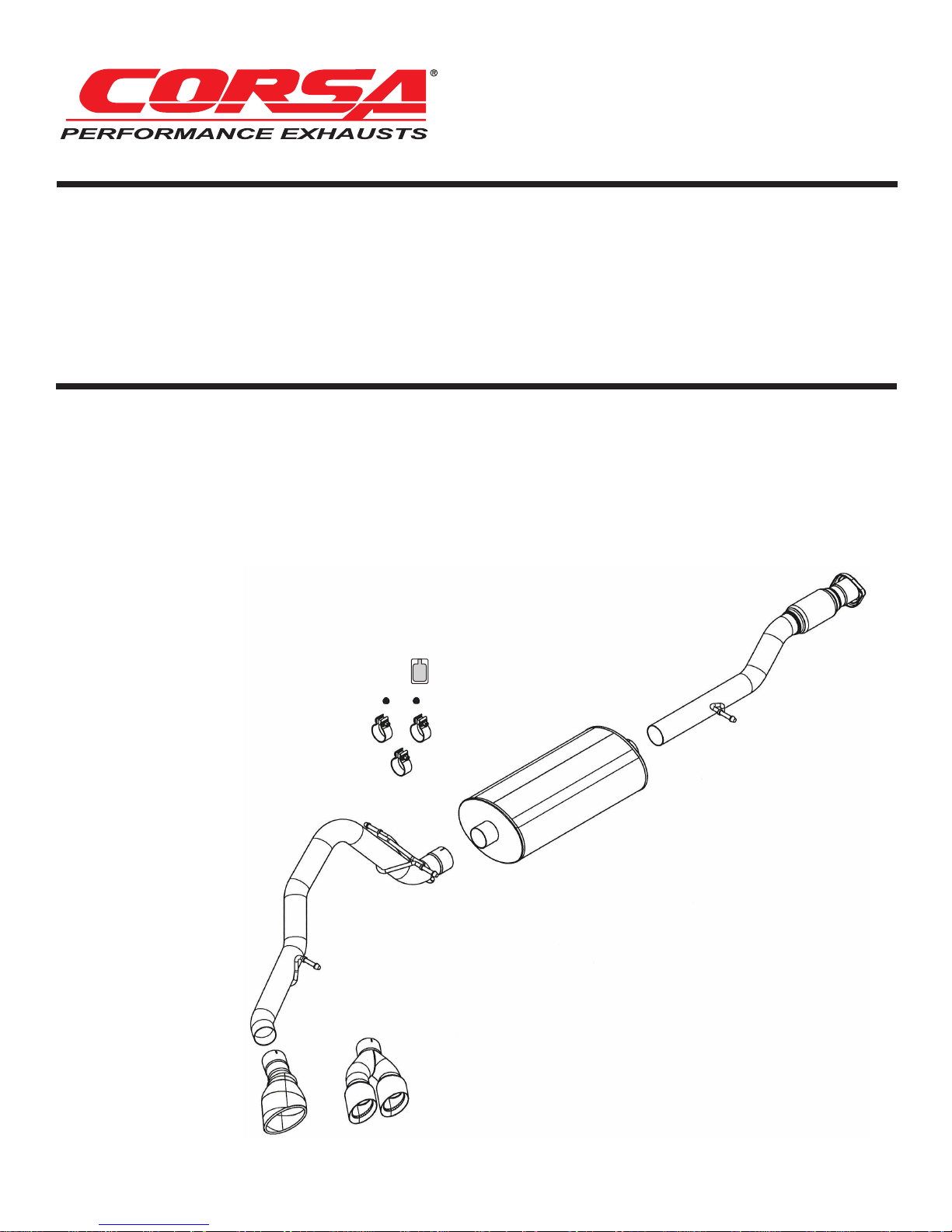
Bill of Materials:
• Head Pipe Assembly
(16A
V4004)
• Touring Muffler 14661 or
Sport Muffler 14638
Recommended Tools:
• Safety Glasses
• 15mm socket and ratchet
• Chain style pipe cutter
• Grommet pullers
• V
ehicle Spare tire removal kit
• Soapy water
• Torque wrench
• Tailpipe Assembly
(16AV4005)
• Side Swept 4.0” Pro-Series Tip
Assembly (16TA3000) or
Hydroformed Tip Assembly
(16SE3006)
• Hardware Kit
(16TA7018)
Anti-Seize
Lubricant
Hardware Kit
(16T
A7018)
Head Pipe Assembly
(16A
V4004)
• (1) Packet Anti-Seize
Lubricant
Tailpipe Assembly
V4005)
(16A
Hydroformed Tip
Assembly (16SE3006)
Touring Muffler 14661
Sport Muffler 14638
Side Swept Pro-Series 4.0”
ip Assembly (16TA3000)
T
Exhaust System Installation: Cat-Back Exhaust System
2007-08 Avalanche/Suburban/Yukon XL 5.3L GMT900
Single Side Exit
Twin Pro-Series 4.0” Tips / SPORT PN 14246 / TOURING PN 14247
Hydroformed Oval Tip / SPORT PN 14248 / TOURING PN 14249
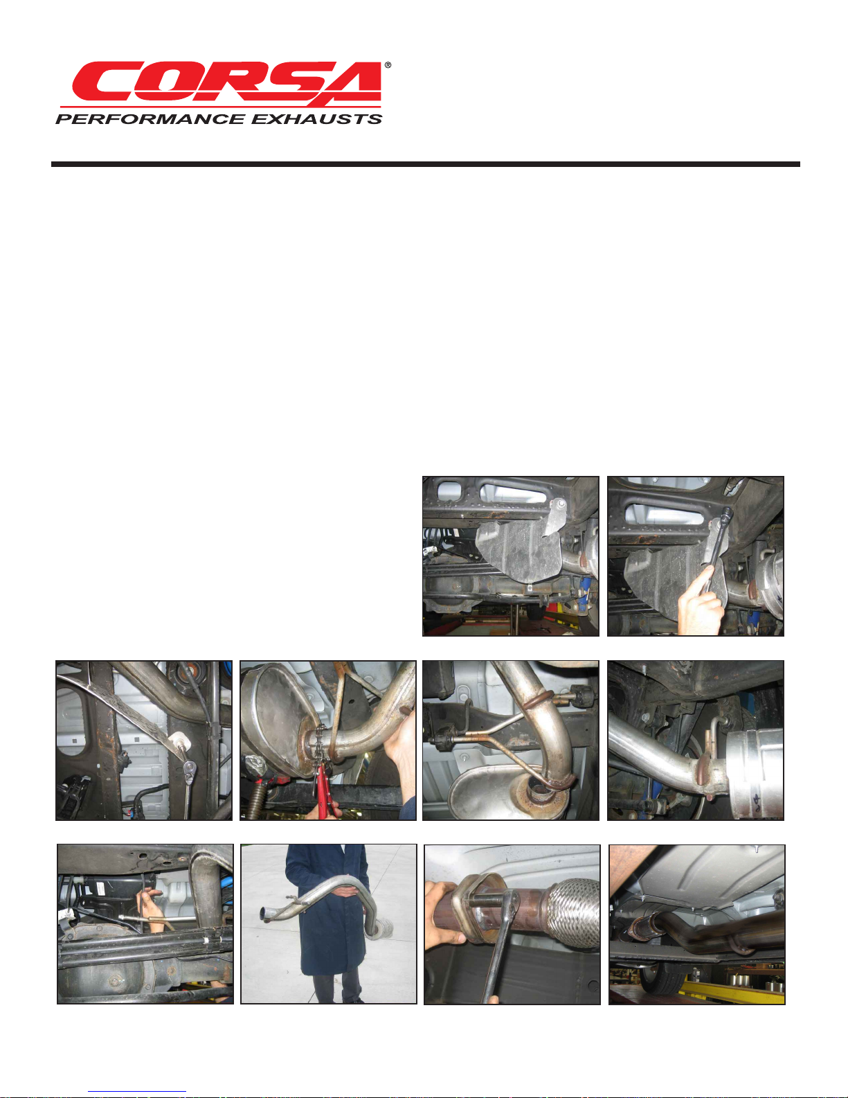
Removal of Stock System:
1) Lower the spare tire by following the instructions in the owner’s manual.
2) Remove the heat shield using a 15mm socket and ratchet.
(See Fig’s A, B & C)
3) Place a chain style cutter around the tailpipe at the tunnel muffler exit and cut the tailpipe
at this location. (See Fig. D)
4) Remove the grommets from the tailpipe hangers using grommet pullers or similar device.
(See Fig’s E & F) NOTE: Using a soapy water solution on the grommet hole will make
the job easier.
5) Remove the tailpipe section from the vehicle by lifting the tailpipe over the rear axle and
backwards under the rear bumper. Be sure to move the rear differential vent hose out of the
way when performing this operation. (See Fig’s G & H)
6) Use a 15mm socket and ratchet to remove
the flange nuts at the flange connection of
the head-pipe. Then remove the grommet at
the hanger location and remove the tunnel
muffler section away from the vehicle. This
completes the removal of the stock system.
(See Fig’s I & J) NOTE: Using a soapy
water solution on the grommet hole will
make the job easier.
FIG. A
FIG. B
FIG. C FIG. D
FIG. G FIG. H
FIG. E FIG. F
FIG. I FIG. J
 Loading...