

Page 1
HomeVision® Pro/Lite
© Corroventa Avfuktning AB
Rev A
1 (30)
User Manual
HomeVision®
Pro/Lite
Page 2

HomeVision® Pro/Lite
© Corroventa Avfuktning AB
Rev A
2 (30)
Table of Contents
Intended use ........................................................................................................................................ 3
Manufacturing Directive ..................................................................................................................... 3
Safety Information............................................................................................................................... 5
Relative humidity and its effect on substances ................................................................................... 6
Control of crawl space humidity ......................................................................................................... 6
Fixed RH control .............................................................................................................................. 6
Mould Growth Index RH control ..................................................................................................... 8
Delivery inspection ............................................................................................................................ 10
Product Overview .............................................................................................................................. 11
Installation ......................................................................................................................................... 12
Installation of Control Unit ............................................................................................................ 12
Installation of Control Panel .......................................................................................................... 13
To use HomeVision® Pro ................................................................................................................... 14
Default view and setup menus, Pro .............................................................................................. 15
To use HomeVision® Lite ................................................................................................................... 20
Default view and setup menus, Lite .............................................................................................. 21
Alarms and service reminders, Pro and Lite ...................................................................................... 24
How to read the log, PRO .............................................................................................................. 26
Service and maintenance .................................................................................................................. 28
Fault finding ....................................................................................................................................... 29
Technical data ................................................................................................................................... 30
Page 3
HomeVision® Pro/Lite
© Corroventa Avfuktning AB
Rev A
3 (30)
User Manual HomeVision®
Intended use
HomeVision® is developed and intended for wireless control and supervision of Corroventa CTR STD-
TT and CTR 300TT2 crawl space dehumidifiers.
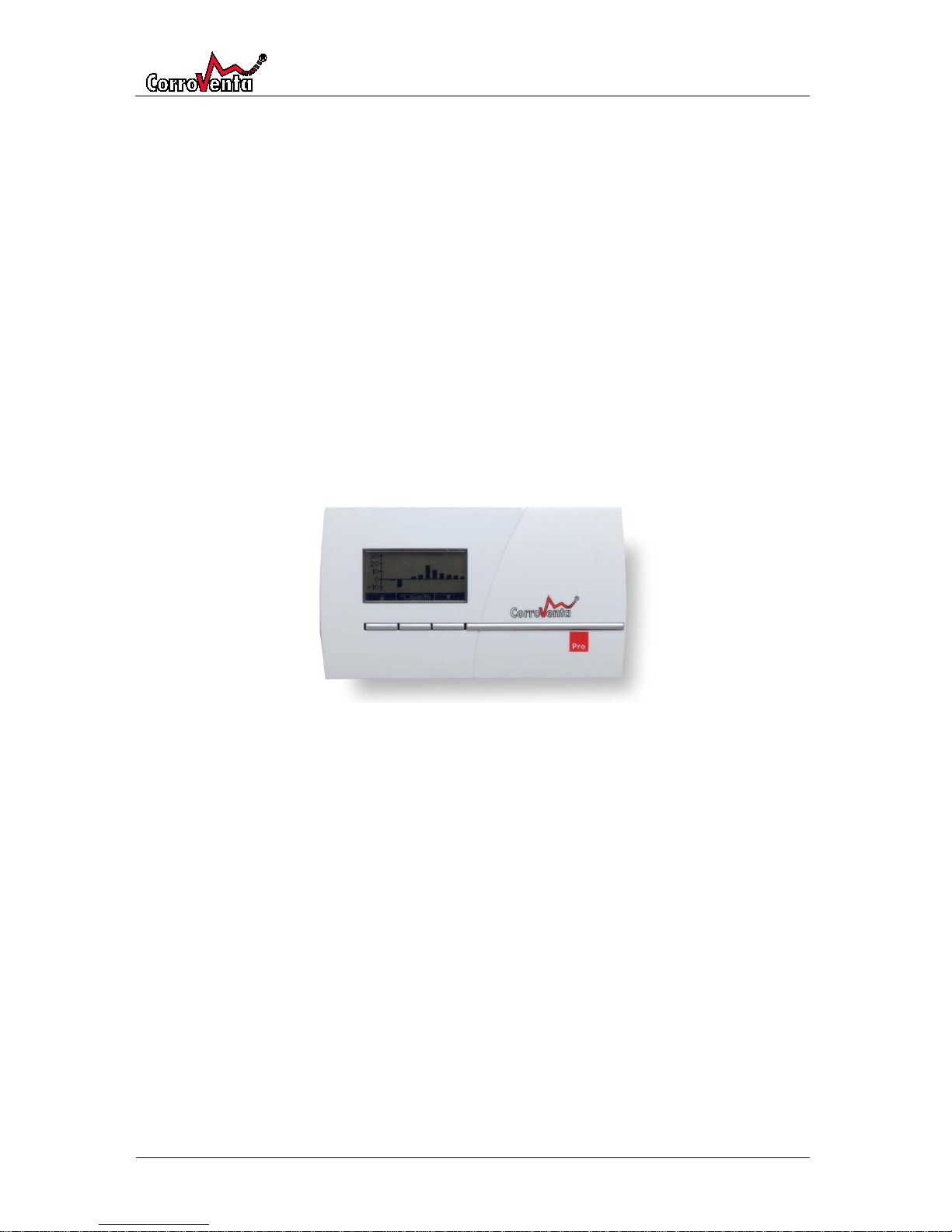
HomeVision® consists of a Control Unit and a wireless Control Panel. The Control Unit is equipped
with built-in temperature and humidity sensor and is mounted in the crawl space and connected to
the dehumidifier. Through use of the Control Panel mounted in the in the apartment the system can
be monitored and its settings adjusted. The Control Panel also displays alarms in case of failures as
well as service reminders for changing filter.
Both versions, Lite and Pro, store log data on USB-stick, supporting service technicians’ in their
installation follow-up and their trouble shooting. The Pro variant also stores a log file in a user
readable format that homeowner himself can use for his own follow-up and analysis.
The Pro version, in addition to all the features of the Lite, also supports Mould Growth Index based
control which for certain installations and circumstances has the potential to lower the energy
consumption even further. Furthermore, the Pro version also has graphic presentation of hours of
operation, average temperature and average humidity.
Features:
• Control and supervision of crawls
space climate, temperature and
relative humidity
• Logging of operation and climate data on USB-
stick – available for users of the Pro version
• Operation indicators and alarms
• Easy to install – wireless Control Panel
• Service reminders
• Graphical display with an easy interface
Manufacturing Directive
HomeVision® Pro and Lite are tested in accordance with LVD and EMC directives. HomeVision® is CE
approved.
Waiver of Liability
• Faulty, incorrect installations and/or incorrect use can cause damage to property and human
injury.
• The manufacturer assumes no responsibility or liability for damages or injuries caused by
non-compliance with the instructions herein, use for other purposes than the intended, or
failure to observe its warnings. Such damage, injuries or liabilities are not covered by the
product warranty.
• The product warranty does not cover consumables or normal wear and tear.
• It is the responsibility of the buyer to inspect the product at time of delivery and before use
to ensure its good function. The product warranty does not cover damage resulting from use
of faulty products.
• Changes or modifications to the equipment must not be made without written consent by
Corroventa Avfuktning AB.
• The product, technical data and/or installation and operation instructions can be changed
without prior notice.
• This manual contains information that is protected by the Intellectual Property laws. No part
of this manual may be copied, stored in an information system or transferred in any form or
in any way without the written consent of Corroventa Avfuktning AB.
Page 4

HomeVision® Pro/Lite
© Corroventa Avfuktning AB
Rev A
4 (30)
Any comments on the contents of this document shall be sent or addressed to:
Corroventa Avfuktning AB Tel 036-37 12 00
Mekanikervägen 3 Fax 036-37 18 30
564 35 Bankeryd E-post [email protected]
SWEDEN
Page 5

HomeVision® Pro/Lite
© Corroventa Avfuktning AB
Rev A
5 (30)
Safety Information
This equipment is not intended to be used by individuals with physical or mental disabilities impeding
their operation or understanding of it or by individuals lacking required knowledge or experience
unless they are supervised and instructed by another person with responsibility for their safety.
Children must only use this equipment under supervision of an adult to ensure that it is not used as a
toy, something that it is not designed for.
Electrical installations made in connection with the installation of the dehumidifier or the
HomeVision® shall be made by authorized personnel in accordance with local and national
regulations.
1. Read and observe the Safety Information in the user manual of the dehumidifer that is to be
installed and/or used.
2. Incorrect settings in HomeVision® can result in damage to property and/or the equipment as
well as too high energy consumption.
3. The Control Unit is connected to the dehumidifier with its cable and is mounted in the crawls
space at approximately half the height in such a way that it is not affected by:
a. The dry air from the dehumidifier.
b. The wet air from the dehumidifier.
c. Radiation from surfaces warmer than ambient air.
d. Radiation from surfaces colder than ambient air.
4. Place and mount the Control Panel:
a. In hallway or similar space where it is often passed and seen so that any appearing
alarm is spotted shortly.
b. Beyond the reach of small children in order to avoid unintentional changes to system
settings.
5. As the Control Panel is intended to be continuously powered through included AC/DC
adapter, do not leave batteries in the Control Panel as many makes and types have a
tendency to leak as they age.
6. To use electrical equipment i a very humid or wet environment can be dangerous. Do not use
or operate the dehumidifier if it, or its Control Unit are in water.
7. Water must not come in contact with or reach the electrical components of the dehumidifier
or the HomeVision®. If this still happens, make sure they are dry before the system is
powered and used again.
8. It is recommended that the power socket used to supply the dehumidifier is protected
through a residual current device / ground fault circuit interrupter.
9. Be careful not to damage the cables. They must not be submerged in water or pass sharp
edges.
10. HomeVision® must not be used with any other accessories than those presented in this
manual or that are explicitly approved by Corroventa Avfuktning AB.
For further advice on product safety and use, please contact the supplier.
Page 6
HomeVision® Pro/Lite
© Corroventa Avfuktning AB
Rev A
6 (30)
Relative humidity and its effect on substances
All air contains more or less moisture but the naked eye cannot see it until it condensates in small
droplets on for instance a metal or glass surface. Already before it is visible however, the moisture
affects substances and production processes, causes corrosion and micro organism growth. In the
Nordic climate in particular, one must always count on ambient humidity due to the large water
surfaces of the many thousands of lakes and of the surrounding sea.
Air humidity is measured and referred to in terms of relative humidity (%RH) which is a measure how
much water it contains relative how much it can contain at given temperature. The higher the
temperature, the more water the air can contain but it is still the Relative Humidity that counts and
that needs to be controlled.
At RH 100% the air is saturated – there is fog and the moisture condensates in small droplets.
Already at RH 60% steel corrodes and at 70% there is a risk for mould growth. As a rule of thumb, RH
50% is a good climate for most substances but in the Nordic countries the humidity is rarely that low.
The yearly average for most places is closer to 80% and it can be as high both summer and winter.
Control of crawl space humidity
When a dehumidifier is installed in the crawl space in accordance with instructions in manual, vents,
cracks and other openings are sealed and the ground is covered with non-aging plastic foil, all
prerequisites are there for achieving and sustaining a good climate where rot, mould and bad smell
are prevented. As an extra prevention, downpipes that end by the foundation wall should be
modified so that the water is lead away from the building and do not leak into the crawl space.
HomeVision® with its wireless Control Panel offers easy and convenient monitoring of the crawls
space environment and allows the user to set desired operating parameters for Fixed RH control and,
for Pro also Mould Growth Index RH control.
Fixed RH control
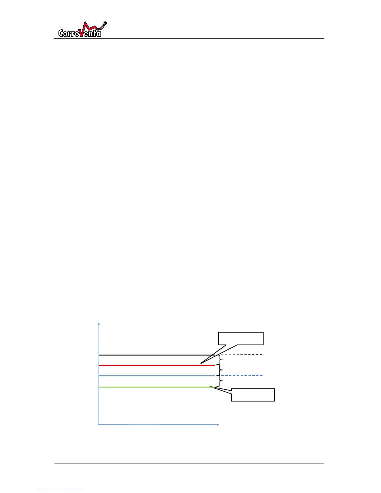
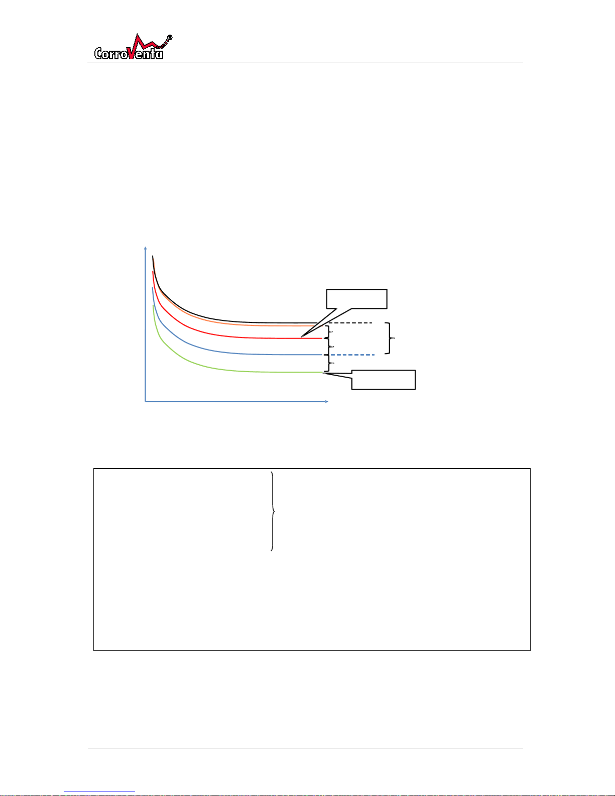
With RH control a setpoint is selected, a relative humidity one wants the system to use as basis for its
dehumidification. Furthermore, one defines an upper and a lower hysteresis as well as an alarm limit,
the latter defining an alarm level at which, should it ever be reached, an automatic alert is triggered
on the Control Panel. The diagram is not to scale but only intended as an illustration of the principle
presented and its different parameters.
% - RH
Temperature
Hysteresis Upper
Hysteresis Lower
Dehumidification On
Dehumidification Off
Alarm +%RH
Alarm level
Setpoint
Page 7
HomeVision® Pro/Lite
© Corroventa Avfuktning AB
Rev A
7 (30)
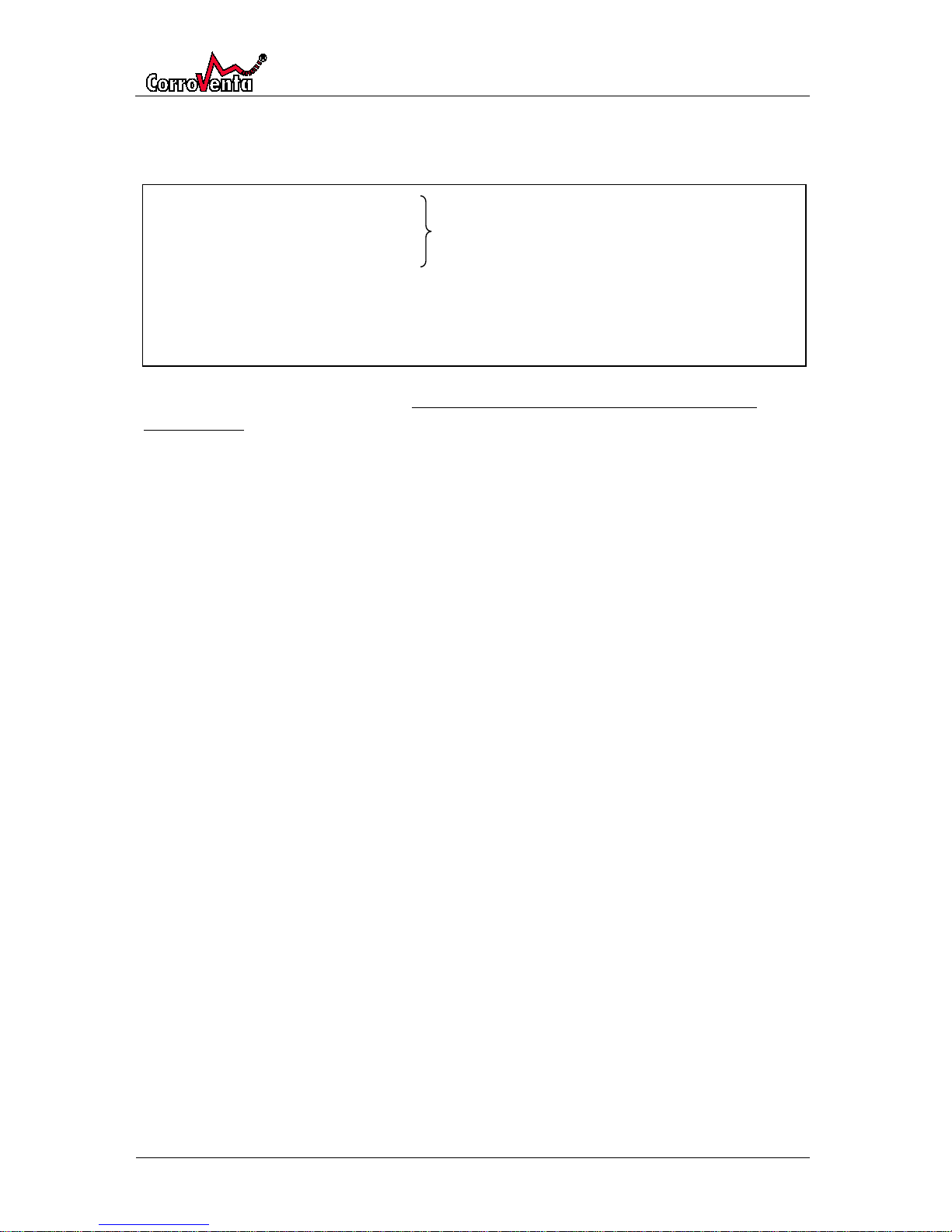
To further facilitate the understanding of the principal, the example below presents all the
parameters and explains how they are applied.
As can be seen from the example above, the setpoint shall not be seen as, or confused with, a
maximum level as it is exceeded with Hysteresis Upper before the dehumidifier is even activated. At
times of high moisture load, the relative humidity can climb even further before it starts declining.
Consequently, the setpoint is, if not perfectly correct, more to be seen as an upper limit for the
average relative humidity and therefore there must always be a margin bigger than the Hysteresis
Upper between the setpoint and the level at which damage arises.
The reason for HomeVision® allowing the user to set the hysteresis is to allow for each and every
installation to be optimized. A too narrow span results in many starts and stops of the dehumidifier
with increased wear on the equipment. A too wide span normally results in the system drying the
crawls space to unnecessarily low levels which consumes more energy than necessary.
Setpoint, %RH: 65%
Activation: Setpoint+Hysteresis Upper = 65% + 4% = 69%
Deactivation: Setpoint +Hysteresis Lower = 65% - 4% = 61%
Hysteresis Upper/Lower: + 4%, -4%
Alarm, +%RH: 10% Added to the activation level to give the Alarm Level.
Alarm Level = Setpoint + Hysteresis Upper + Alarm =
65% + 4% + 10 % = 79%
Page 8
HomeVision® Pro/Lite
© Corroventa Avfuktning AB
Rev A
8 (30)
Mould Growth Index RH control
In addition to Fixed RH control, HomeVision® Pro also implements Mould Growth Index, MGI,
control. The control mechanism makes use of the fact that mould growth, in addition to being
humidity dependant also is temperature dependant. At lower temperatures, higher humidity can be
tolerated without causing mould growth, the positive side of which is of course the potential to save
further energy.
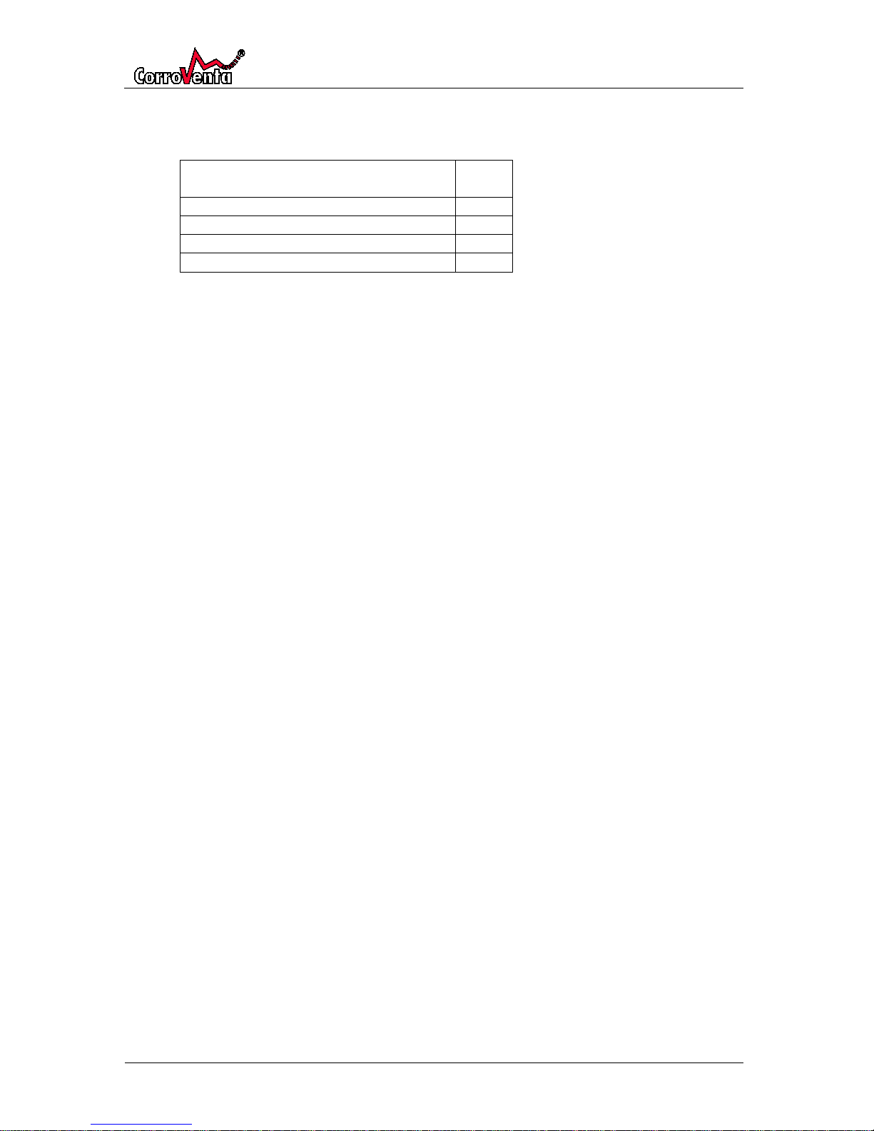
The MGI control principle, as explained implemented in HomeVision® Pro for its energy saving
potential, is visualized in the schematic diagram below. The diagram is not to scale but intended only
to explain and clarify the principle and its parameters.
The upper curve, the Mould Growth Index curve, is programmed in HomeVision® Pro and is not
affected by user settings. The user is instead allowed to set RH safety margin, Hysteresis Upper and
Lower and alarm limit, the meanings of which are explained by the following example.
The principals are familiar to those acquainted the Fixed RH control but instead of a setpoint a safety
margin is defined. As with the Fixed setpoint, the RH safety margin is exceed by the Hysteresis Upper
before the dehumidifier is activated. The RH safety margin does thus not constitute a maximum
level. As for Hysteresis and the Alarm, these function the same way with MGI as with Fixed.
RH safety margin, %RH: -15% Activation:
Current MGI– RH safety margin + Hysteresis Upper =
= Current MGI – 15% + 4%
Hysteresis Upper/Lower: + 4%, -4% Deactivation:
Current MGI – RH safety margin – Hysteresis Lower =
= Current MGI– 15% - 4%
Alarm, +%RH: 10% Added to activation to level to give Alarm level.
Alarm level:
Current MGI – RH safety margin + Hysteresis Upper + Alarm=
= Current MGI – 15% + 4% + 10 %
Current MGI = The relative humidity that for current temperature is the lower limit for mould growth.
% - RH
Temperature
Mould Growth Index curve
RH - MGI
Safety Margin
-
Hysteresis Upper
Hysteresis Lower
Dehumidification Off
Dehumification On
Alarm, +%RH
Page 9

HomeVision® Pro/Lite
© Corroventa Avfuktning AB
Rev A
9 (30)
As the reader has understood already, it is in the lower temperature interval that the relative
humidity supported by Mould Growth Index can be allowed to rise somewhat higher and thus
achieve an energy saving. For higher temperatures, the two control modes coincide and the energy
consumption is thus identical.
Page 10
HomeVision® Pro/Lite
© Corroventa Avfuktning AB
Rev A
10 (30)
Delivery inspection
HomeVision® is delivered with the following items included:
Control Unit with cable connection to CTR
STD-TT or CTR 300TT2 dehumidifier
1 pc
Control Panel with USB memory stick
1 pc
Power adaptor for Control Panel
1 pc
Batteries for Control Panel, AAA cells
2 pcs
User Manual
1 pc
*) Please note that the batteries are already mounted in the Control Panel. To use them, the isolating
piece of plastic between the battery pole and the contact spring must be removed. The batteries are
intended for use during installation of the equipment. For normal use, the Control Panel shall be
powered through the power adaptor.
Page 11
HomeVision® Pro/Lite
© Corroventa Avfuktning AB
Rev A
11 (30)
Product Overview
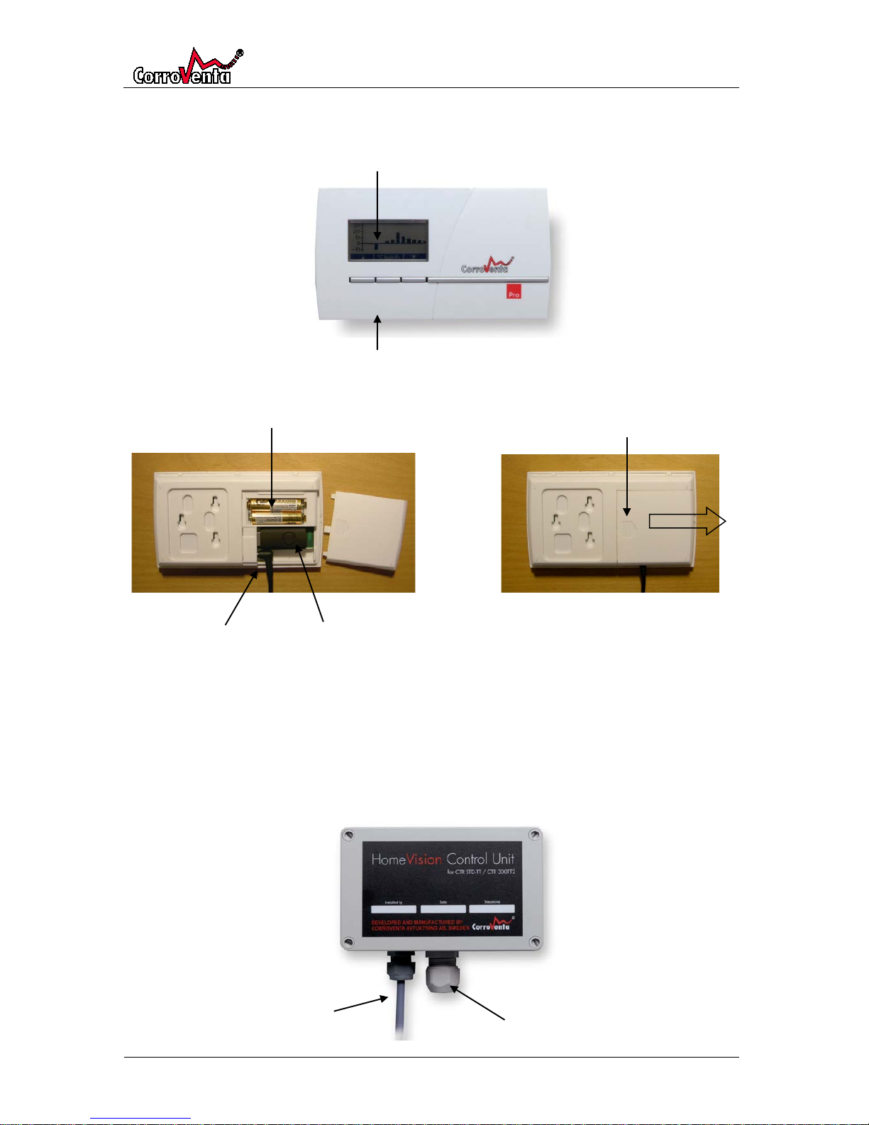
Control Panel
The battery compartment is opened by pushing by the arrow symbol and simultaneously sliding the
lid in the arrow direction as shown in the picture below.
Control Unit
Control unit is mounted with sensor downwards.
Push arrow symbol and
slide the lid to the right
Batteries, AAA cells, 2pcs
Connector for
power adaptor
USB memory stick
Display
Three push buttons
Temperature and humidity sensor
Cable for connection to
dehumidifier
Page 12
HomeVision® Pro/Lite
© Corroventa Avfuktning AB
Rev A
12 (30)
Installation
Installation of Control Unit
When installing the Control Unit, prepare the Control Panel by removing the battery protection and
bring it to the crawl space.
1. Mount the Control Unit where its cable can reach the dehumidifier and where its
measurements of temperature and relative humidity will be representative of the ambient
crawl space environment, securing that:
• The unit is at approaximately half the height of the crawl space.
• The unit is not directly affected by the dry air from the dehumidifier.
• The unit is not directly affected by the wet air from the dehumidifier.
• The unit is not affected by radiation from heat sources/surfaces hotter than ambient air.
• The unit is not affected by radiation from surfaces colder than ambient air.
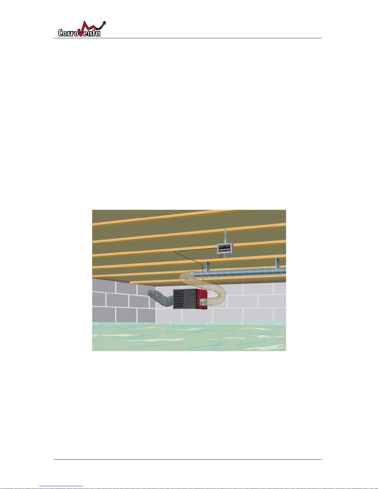
The Control Unit is mounted in bracket, part of the installation kit (Monteringskit TT Multi)
with the sensor downwards. The bracket is preferably fixed as depicted below.
Page 13
HomeVision® Pro/Lite
© Corroventa Avfuktning AB
Rev A
13 (30)
2. Connect the Control Unit cable to the dehumidifier.
3. Provided that the dehumidifier installation is completed, connect its power cable. Take the
Control Panel and:
a) In the default view,push <Setup>.
b) When the Adminstration view to the right is
presented, push <Change>.
c) Push down arrow and verify that the “Connect
new unit ” alternative “Standard” is selected.
d) Push <Select> and when ”Standard” is visible,
push <Save>.
The display now shows the text ”Attempting to pair up…” and as soon as connection is
established “Pairing successful” is presented which is acknowledged by pushing <OK>.
The Control Panel returns to the default view where status indications, temperature and
relative humidity are presented. It may take up to 45 seconds before current status and
values are presented.
In the default view there is also an indication of the radio signal quality. The indication is
based on how many data packages are received at their first transmission why the
quality normally builds up over time. It always shows level one in the beginning and is
therefore not to be compared with the signal strength indication of a cellular phone.
Note: When the Control Unit is powered, it is open to pairing for two minutes only.
Therefore,as a first measure when failing to pair the system, restart the Control Unit and
try again.
Installation of Control Panel
When the Control Unit is installed and radio connection between that and the Control Panel is
established, proceed as follows:
1. Select position for the Control Panel where there is power outlet within reach of the power
adaptor cable and preferably where any alarm would be noticed as soon as possible (the
screen back light starts to flash when alarms are presented). Furthermore, if there are small
children in the household, the Control Panel should be placed beyond their reach.
Put the Control Panel at the intended position and leave it there for a couple of minutes to
let the signal quality indication reflect current conditions. Verify that at the indication is at
level two or higher.
2. Detach the wall bracket from the Control Panel by pushing it downwards. Hold the bracket to
the wall at the intended position and mark the position of the three holes to be drilled. Drill
the holes and insert the wall plugs. Fix the bracket to the wall using the three screws.
Page 14
HomeVision® Pro/Lite
© Corroventa Avfuktning AB
Rev A
14 (30)
3. Remove the batteries from the Control Panel and connect the power adaptor. (The Control
Panel, if correctly paired, will automatically reconnect the Control Unit after power down.)
4. Mount the Control Panel on the wall bracket by holding it over the bracket and pulling it
downwards. Connect the power adaptor to the power outlet.
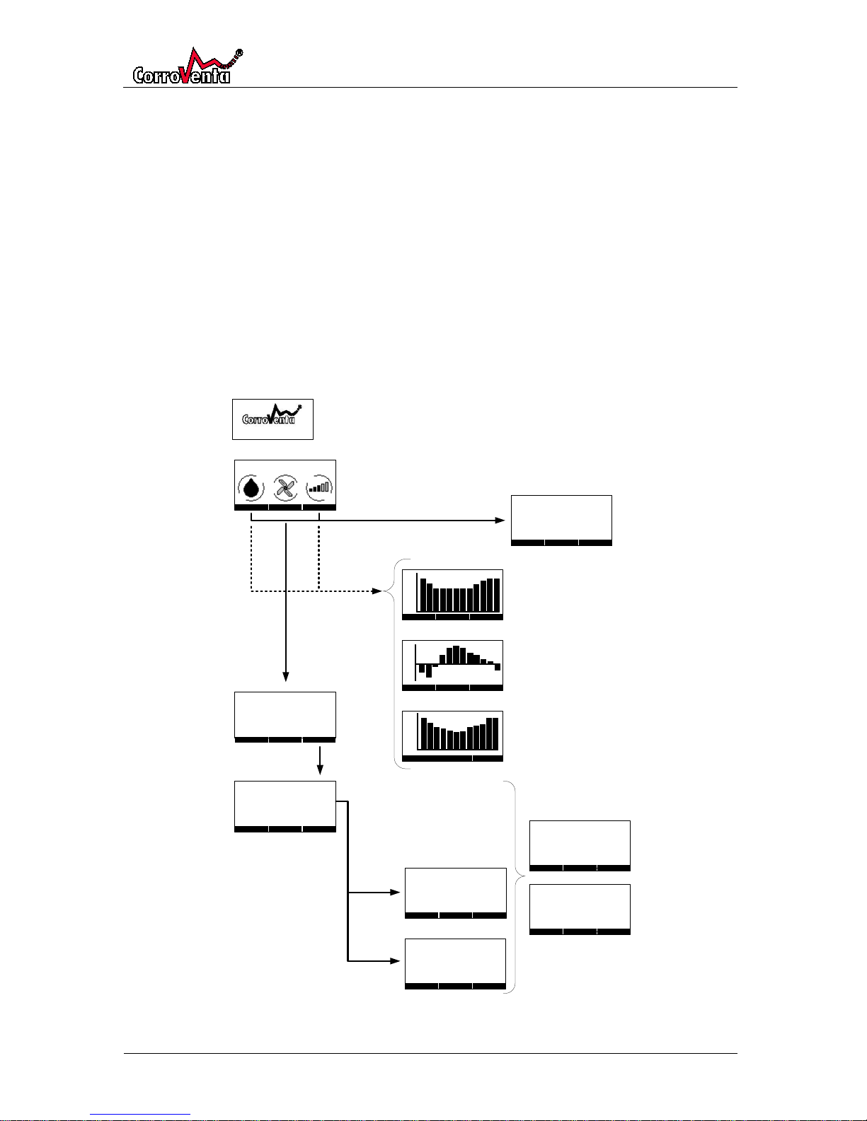
To use HomeVision® Pro
HomeVision® has an easily understood user interface with a display and three push buttons. The
push buttons are so called soft buttons meaning that their respective functions vary with the menus
to make the maneuvering as simple as possible.
The menus are all depicted below except for automatic alarms and reminder which are present in
separate chapter. From the default view, the menus are reached through the center setup button.
The up and the down arrows in the default view are used to present operation, temperature and
relative humidity statistics. In the statistics views, the first column from the left is the current
calendar month, followed by the last completed calendar month and so forth.
Page 15
HomeVision® Pro/Lite
© Corroventa Avfuktning AB
Rev A
15 (30)
Default view and setup menus, Pro
Default view
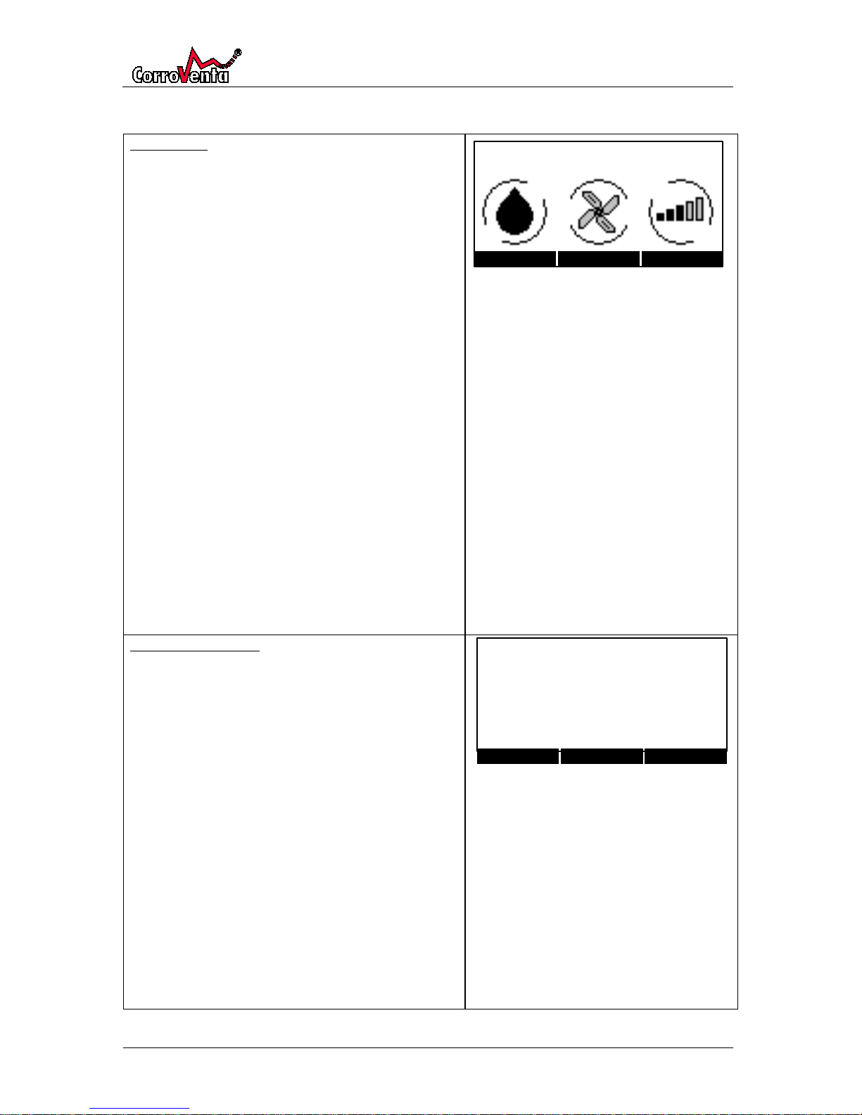
In the default view, current crawl space relative
humidity and temperature are presented. The
indications in the lower part of the screen show, from
left:
• Dehumidification, if the dehumidifier is
currently active or not. When active, the water
level in the droplet is moving and the outer
circle rotating.
• Fan – if the fan is currently active or not. When
active the fan wheel and the outer circle are
both rotating.
• Signal quality, how good the connection with
the Control Unit is. The higher the indication,
the better quality. When connection is lost, the
entire symbol flashes.
Please note that the signal quality reflects how
many data packages are correctly received in
their first transmission. The level normally
builds up over time and may then vary slightly.
Standard paired systems automatically
reconnect after power reset. When the Control
Unit has been powered down it takes
approximately three minutes for the system to
reestablish connection.
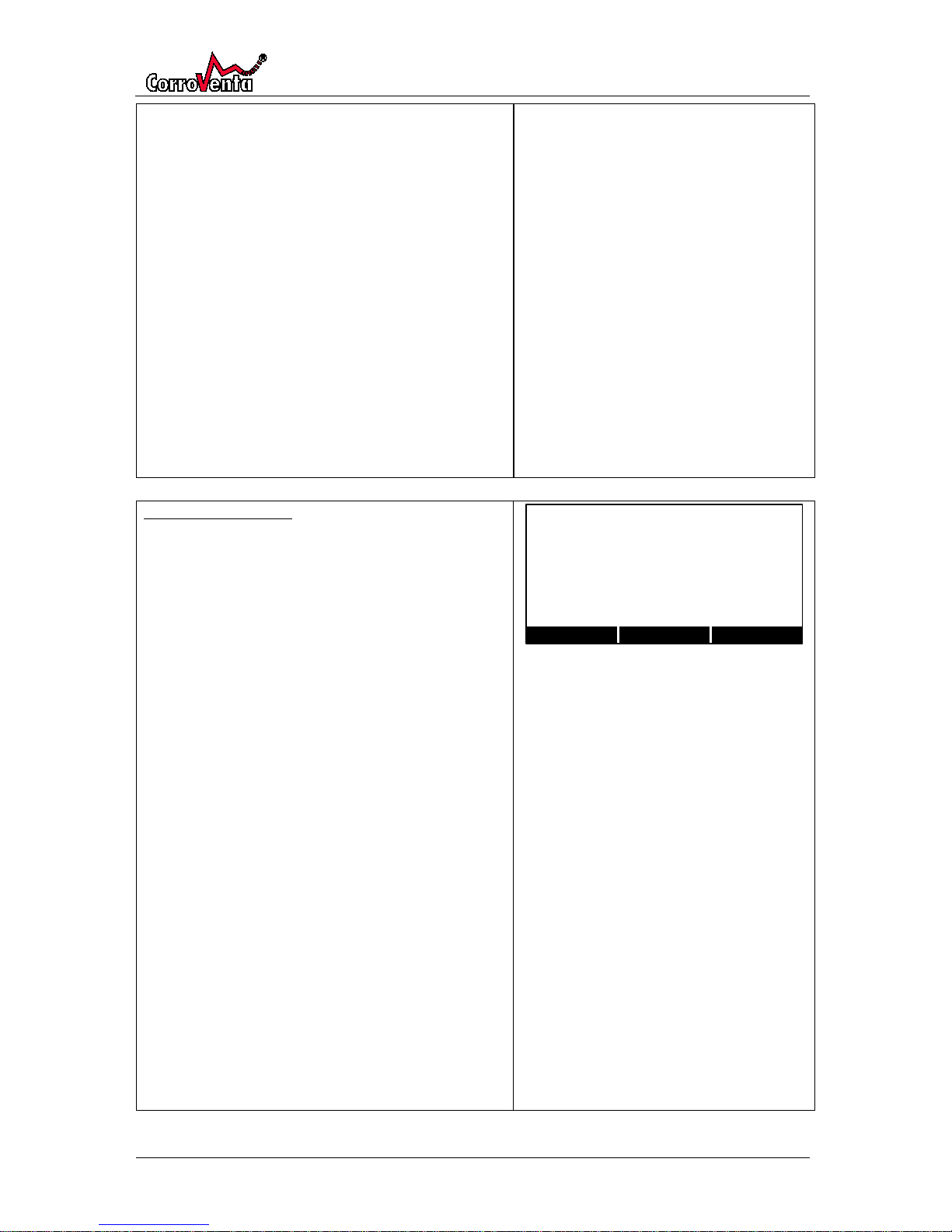
Administration menu
This menu is accessed from the default view by
pushing <Setup>.
To change parameters, push <Change>, use down
arrow to select parameter to change and push
<Select>.
Select parameter value of choice using the arrows and
then push <Save>.
Date is in the format YY-MM-DD.
”Connect new unit” is normally only used at time of
installation. It shall be set to Standard which makes the
system automatically reconnect after power reset. The
Service alternative is only for use by service
technicians, establishing at temporary connection.
Service paired systems do not reconnect after power
reset. The Control Unit only allows pairing of new
Control Panel for two minutes after restart.
Page 16
HomeVision® Pro/Lite
© Corroventa Avfuktning AB
Rev A
16 (30)
”Remove USB stick” prepares the Control Panel for
removal of the USB stick by temporarily stopping the
logging process, preventing the files from being
corrupted. Always use this function when removing
the USB.
Note: The Pro version stores a user readable log file in
CSV (comma separated) format on the USB stick. The
file can be analyzed and studied with for instance
Microsoft Excel. Always make a copy of the log file to a
different location and then use that file, not the
original in order to prevent the file from being
corrupted. Put the USB-stick back in the Control Panel
as soon as the copy is made in order not to lose any log
data.
”Select language” allows for the user to select Control
Panel language.
Mode and reset menu
Accessed from the default view by pushing <Setup>
and then down arrow.
To change parameters, push <Change>, use down
arrow to select parameter to change and push
<Select>.
Select parameter value of choice using the arrows and
then push <Save>.
”Continuous ventilation” determines whether the fan
shall operate continuously or only when the
dehumidifier is active. Normally it is recommended to
have continuous ventilation, particularly if there are
problems with radon or bad smell from the crawl
space. If no such problems exist, deactivation of
continuous fan can be considered in order to save
energy.
”RH Control Mode” allows for selection of either Fixed
control with setpoint RH% or Mould Growth Index
control allowing the maximum relative humidity vary
with the temperature. Both these modes and
principles are explained in previous chapters of this
manual.
”Reset service indicator” allows for reset of the built-in
service timer that provides a yearly service reminder.
Normally this function is never used as the reset is
automatic when performed service is acknowledged
through the service reminder screen.
Page 17
HomeVision® Pro/Lite
© Corroventa Avfuktning AB
Rev A
17 (30)
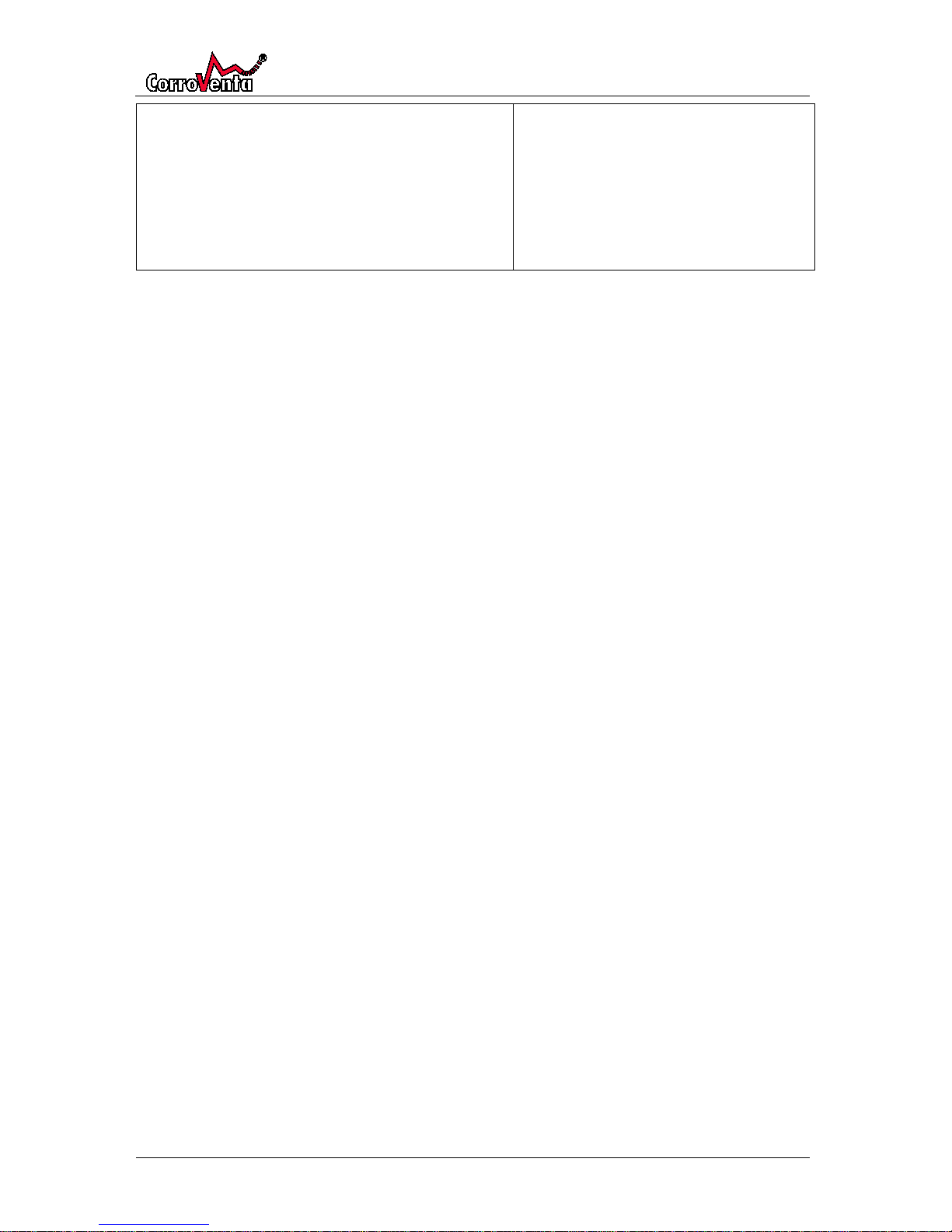
”Reset all settings” makes the system delete all user
settings and return to factory defaults. Factory default
is control mode Fixed with setpoint 65%RH and with
continuous ventilation.
Page 18
HomeVision® Pro/Lite
© Corroventa Avfuktning AB
Rev A
18 (30)
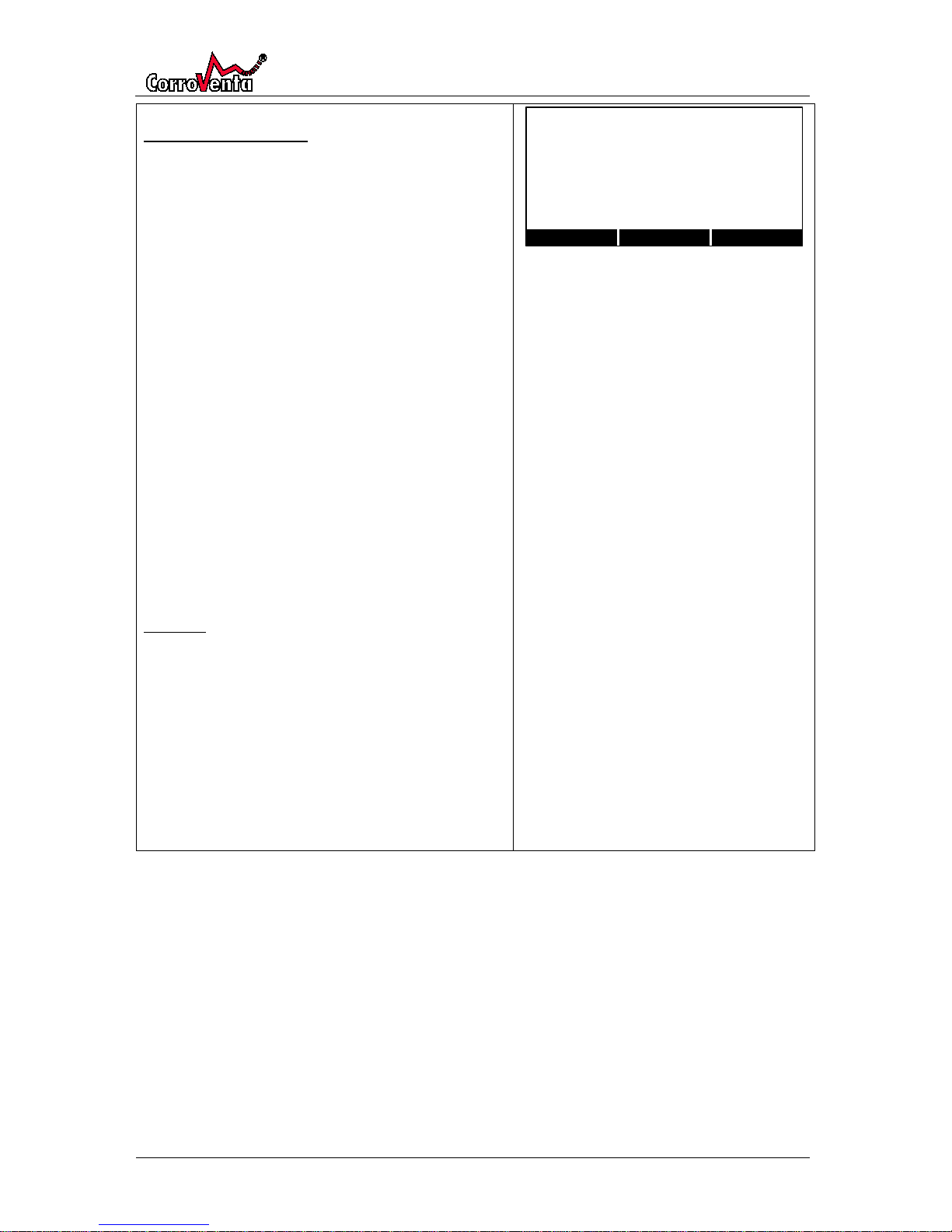
RH Control Mode - Fixed
Accessible from default view by pushing <Setup> and
then twice down arrow provided control mode Fixed is
selected in the mode and reset menu.
To change parameters, push <Change>, use down
arrow to select parameter to change and push
<Select>.
Select parameter value of choice using the arrows and
then push <Save>.
”%RH Setpoint” defines the basis for the
dehumidification. The setpoint is not to be seen as
maximum relative humidity. The setpoint is exceeded
by the Hysteresis Upper before the dehumidifier is
even activated.
”Hysteresis, Upper/Lower” defines at what percentage
points, respectively above and below the setpoint that
the dehumidifier shall activate and deactivate.
”Alarm, +RH%” defines at what percentage point
above the activation level that the humidity alarm on
the Control Panel shall be activated.
Example:
Setpoint: 65%
Hysteresis Upper/Lower: 4% / - 4%
Alarm, +%RH: 10%
Dehumidifier activation = 65% + 4% = 69%
Dehumidifier deactivation = 65%-4%=61%
Alarm is triggered at setpoint 65% + 4 % Hysteresis
Upper + 10% Alarm =
(65+4+10)%RH= 79%RH
Page 19
HomeVision® Pro/Lite
© Corroventa Avfuktning AB
Rev A
19 (30)
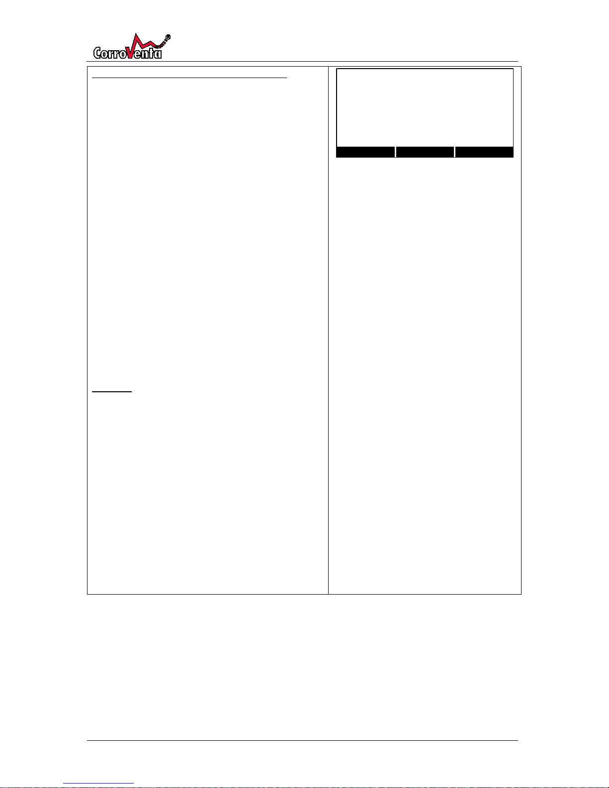
RH Control Mode, Mould Growth Index (MGI)
Accessible from default view by pushing <Setup> and
then twice down arrow provided control mode MGI is
selected in the mode and reset menu.
To change parameters, push <Change>, use down
arrow to select parameter to change and push
<Select>.
Select parameter value of choice using the arrows and
then push <Save>.
”%RH Safety Margin” defines at what number of
percentage points below current MGI RH%, the lower
limit for mould growth at given temperature, that the
dehumidifier shall operate.
”Hysteresis, Upper/Lower” defines at what percentage
points, respectively above and below the RH Safety
Margin that the dehumidifier shall activate and
deactivate.
”Alarm, +RH%” defines at what percentage point
above the activation level that the humidity alarm on
the Control Panel shall be activated.
Example:
RH Safety Margin: -15%
Hysteresis Upper/Lower: 4% / - 4%
Alarm, +%RH: 10%
Dehumidifier activation = Current MGI - 15% + 4%
= Current MGI - 11%
Dehumidifier deactivation = Current MGI - 15% - 4%
= Current MGI - 19%
The alarm is triggered at Current MGI - 15 % Safety
Margin + 4 % Hysteresis Upper + 10 % Alarm which
equals Current MGI - 1 %.
In other words, the alarm will be triggered at a relative
humidity one percentage point below the lower limit
for mould growth at given temperature.
Page 20
HomeVision® Pro/Lite
© Corroventa Avfuktning AB
Rev A
20 (30)
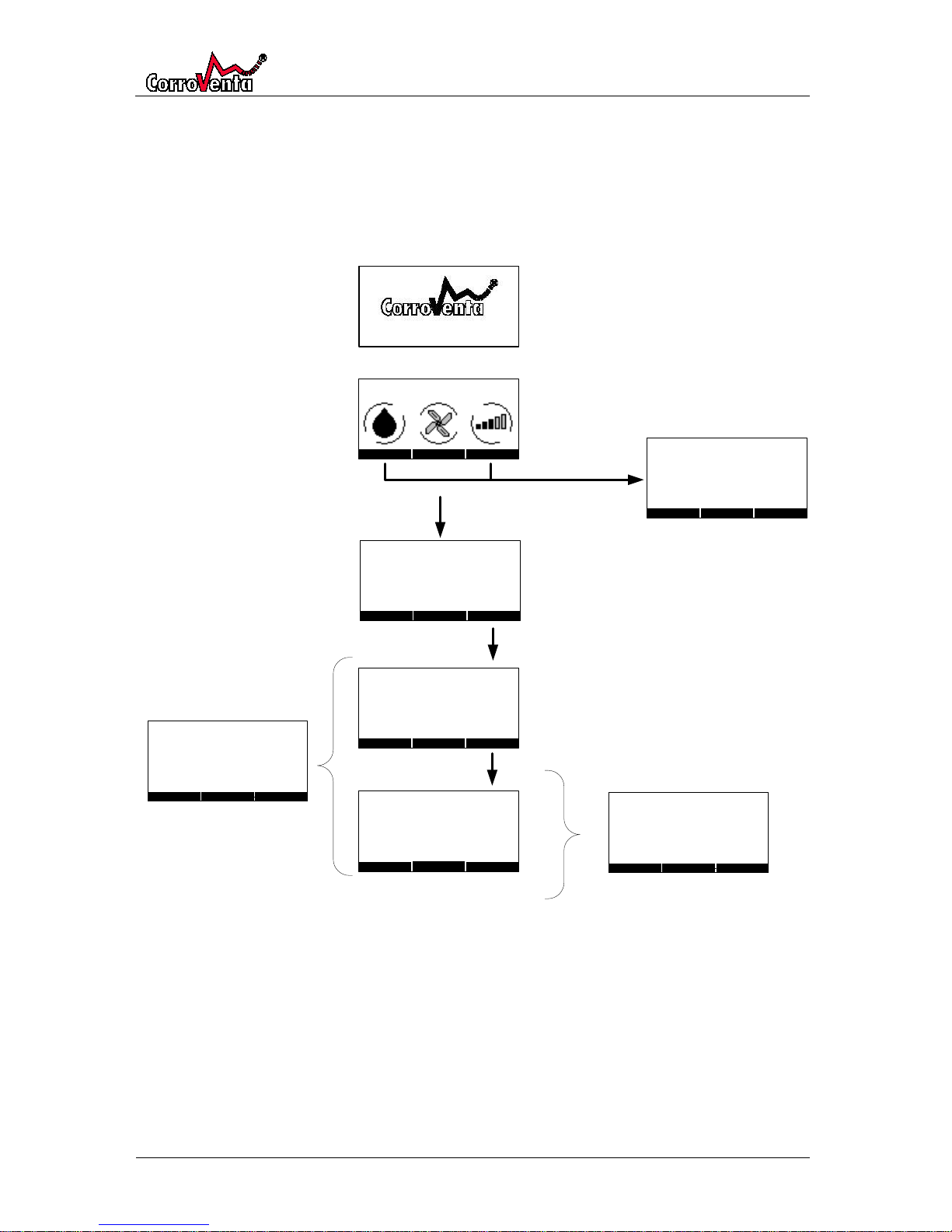
To use HomeVision® Lite
HomeVision® has an easily understood user interface with a display and three push buttons. The
push buttons are so called soft buttons meaning that their respective functions vary with the menus
to make the maneuvering as simple as possible.
The menus are all depicted below except for automatic alarms and reminder which are present in
separate chapter. From the default view, the menus are reached through the center setup button.
Page 21
HomeVision® Pro/Lite
© Corroventa Avfuktning AB
Rev A
21 (30)
Default view and setup menus, Lite
Default view
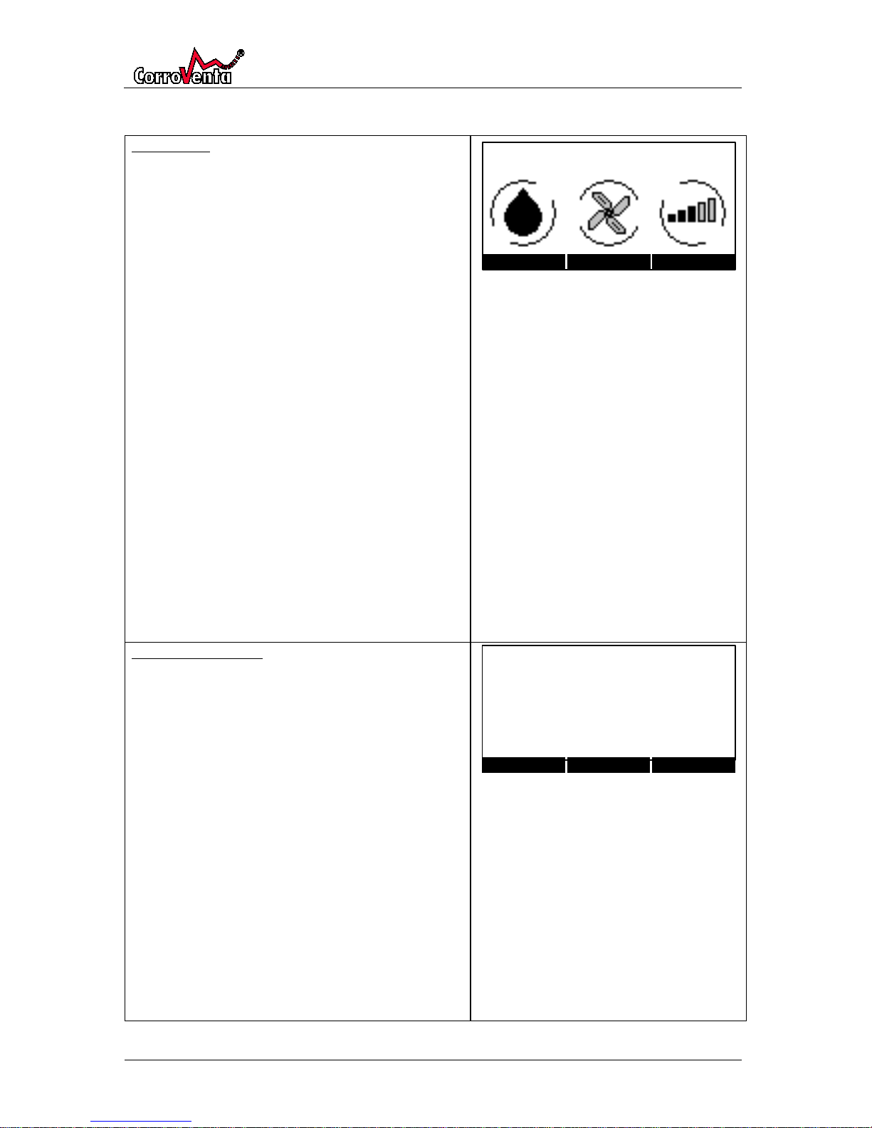
In the default view, current crawl space relative
humidity and temperature are presented. The
indications in the lower part of the screen show, from
left:
• Dehumidification, if the dehumidifier is
currently active or not. When active, the water
level in the droplet is moving and the outer
circle rotating.
• Fan – if the fan is currently active or not. When
active the fan wheel and the outer circle are
both rotating.
• Signal quality, how good the connection with
the Control Unit is. The higher the indication,
the better quality. When connection is lost, the
entire symbol flashes.
Please note that the signal quality reflects how
many data packages are correctly received in
their first transmission. The level normally
builds up over time and may then vary slightly.
Standard paired systems automatically
reconnect after power reset. When the Control
Unit has been powered down it takes
approximately three minutes for the system to
reestablish connection.
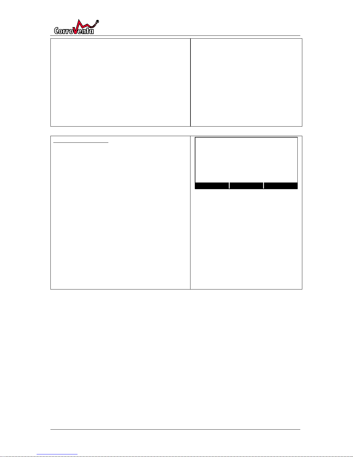
Administration menu
This menu is accessed from the default view by
pushing <Setup>.
To change parameters, push <Change>, use down
arrow to select parameter to change and push
<Select>.
Select parameter value of choice using the arrows and
then push <Save>.
Date is in the format YY-MM-DD.
”Connect new unit” is normally only used at time of
installation. It shall be set to Standard which makes the
system automatically reconnect after power reset. The
Service alternative is only for use by service
technicians, establishing at temporary connection.
Service paired systems do not reconnect after power
reset. The Control Unit only allows pairing of new
Control Panel for two minutes after restart.
Page 22
HomeVision® Pro/Lite
© Corroventa Avfuktning AB
Rev A
22 (30)
”Remove USB stick” prepares the Control Panel for
removal of the USB stick by temporarily stopping the
logging process, preventing the files from being
corrupted. Always use this function when removing
the USB.
Note: The log file on the USB memory stick is intended
for service technicians only and cannot be read with
standard software.
”Select language” allows for the user to select Control
Panel language.
Mode and reset menu
Accessed from the default view by pushing <Setup>
and then down arrow.
To change parameters, push <Change>, use down
arrow to select parameter to change and push
<Select>.
Select parameter value of choice using the arrows and
then push <Save>.
”Reset service indicator” allows for reset of the built-in
service timer that provides a yearly service reminder.
Normally this function is never used as the reset is
automatic when performed service is acknowledged
through the service reminder screen.
”Reset all settings” makes the system delete all user
settings and return to factory defaults. Factory default
is control mode Fixed with setpoint 65%RH and with
continuous ventilation.
Page 23
HomeVision® Pro/Lite
© Corroventa Avfuktning AB
Rev A
23 (30)
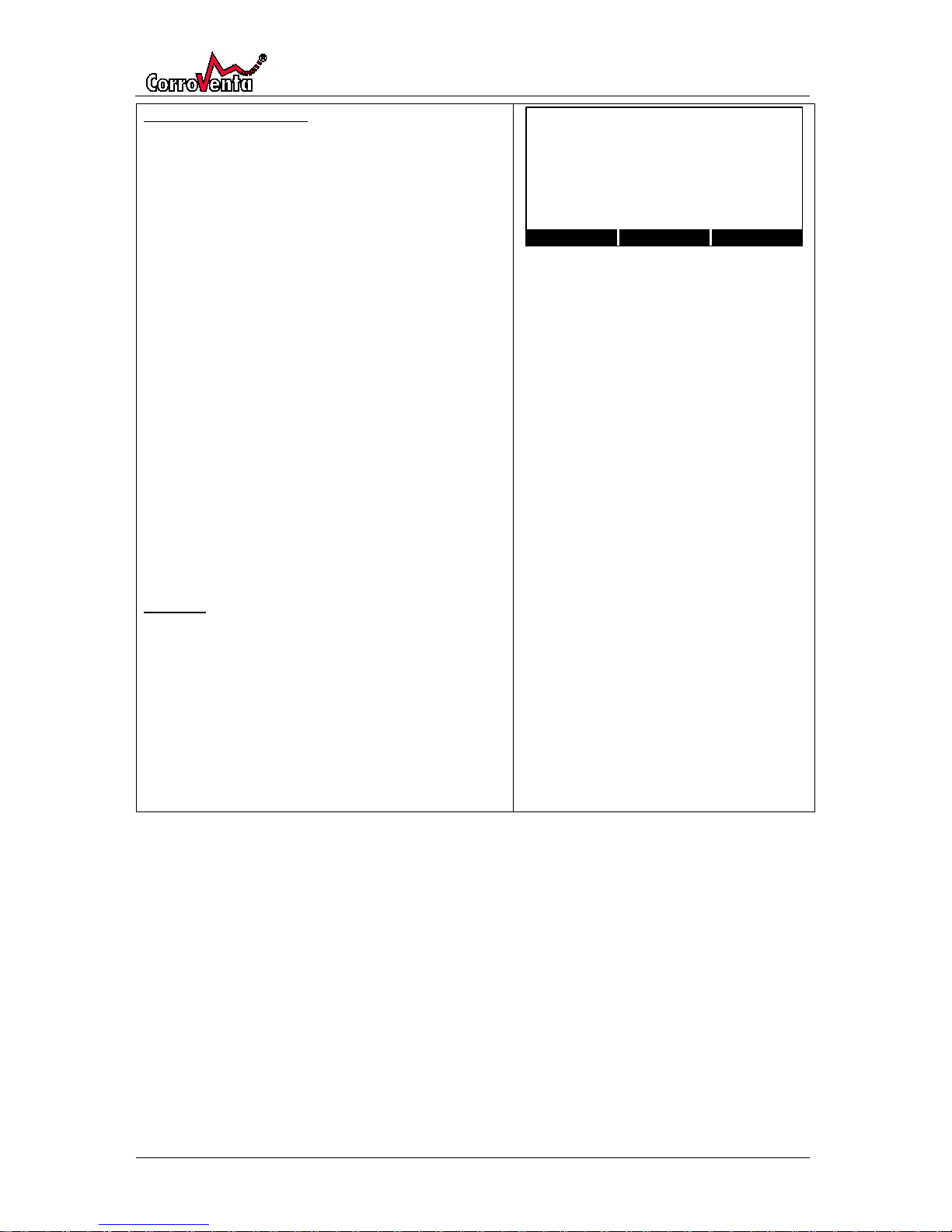
RH Control Mode - Fixed
Accessible from default view by pushing <Setup> and
then twice down arrow provided control mode Fixed is
selected in the mode and reset menu.
To change parameters, push <Change>, use down
arrow to select parameter to change and push
<Select>.
Select parameter value of choice using the arrows and
then push <Save>.
”%RH Setpoint” defines the basis for the
dehumidification. The setpoint is not to be seen as
maximum relative humidity. The setpoint is exceeded
by the Hysteresis Upper before the dehumidifier is
even activated.
”Hysteresis, Upper/Lower” defines at what percentage
points, respectively above and below the setpoint that
the dehumidifier shall activate and deactivate.
”Alarm, +RH%” defines at what percentage point
above the activation level that the humidity alarm on
the Control Panel shall be activated.
Example:
Setpoint: 65%
Hysteresis Upper/Lower: 4% / - 4%
Alarm, +%RH: 10%
Dehumidifier activation = 65% + 4% = 69%
Dehumidifier deactivation = 65%-4%=61%
Alarm is triggered at setpoint 65% + 4 % Hysteresis
Upper + 10% Alarm =
(65+4+10)%RH= 79%RH
Page 24
HomeVision® Pro/Lite
© Corroventa Avfuktning AB
Rev A
24 (30)
Alarms and service reminders, Pro and Lite
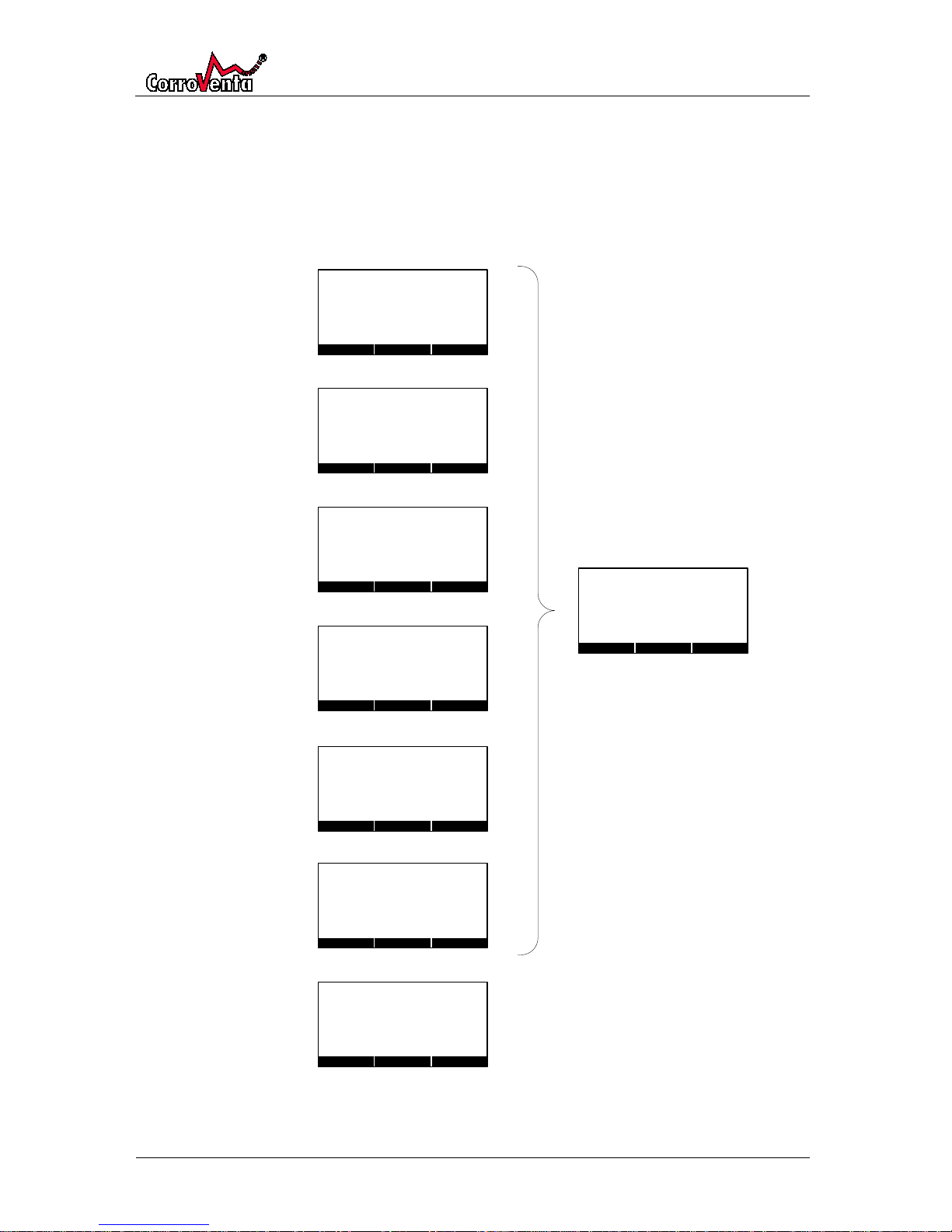
In both versions, Pro and Lite, there are a number of automatic alarms and reminders implemented
intended to alert the user to any disruptions or system failures and to remind of service needs.
For all these alarms and reminders, except for the Log warning, the <Next> button leads to a
confirmation screen depicted below to the right. When <OK> is pushed, the confirmation is logged
with date and time which is a support for service technicians in any subsequent trouble shooting.
Below the picture is a table with further explanations of the screens.
Page 25
HomeVision® Pro/Lite
© Corroventa Avfuktning AB
Rev A
25 (30)
Skärmbild
Förklaring
ALARM 1
The dehumidifier’s automatic overheating protection has temporarily stopped the
system. The dehumidifier restarts as soon as the temperature has sunk but to
prevent this from happening again it should be attended to in accordance with its
manual. A likely cause of the incident is, as the text says, that the filter is clogged
and needs to be replaced. When the corrective measures have been taken,
confirm them by pushing <OK>. The alarm will then disappear and a log post is
created.
If the problems remain after these measures, please contact your retailer.
LARM 2
Like the text says, the dehumidifier has failed and needs to be repaired by
professional service technician. The dehumidifier does no longer function. Please
contact your retailer as soon as possible.
LARM 3
The relative humidity is, or has temporarily been, above the alarm level. As a first
measure, verify that the alarm level setting is relevant, that the humidity is indeed
a problem. Thereafter, use the dehumidifier manual to locate the error. Confirm
corrective actions performed by pushing <OK>. The alarm will then disappear and
a log post is created.
LARM 4
Like the text says, the Control Unit has failed and needs to be repaired by
professional service technician. The dehumidifier and its built-in fan are now
running continuously to prevent damage on the property. As continuous
dehumidification means significantly higher energy consumption, please contact
your retailer as soon as possible.
LARM 5
This alarm is activated when the Control Panel has not heard radio traffic from the
Control Unit for sixty minutes. If the connection is reestablished, the alarm
disappears automatically.
As a first measure, verify that the dehumidifier is powered so that power loss is not
the reason for the alarm. If the problem remains, restart the dehumidifier by
disconnecting and then reconnecting power and pair the Control Panel again
according to the installation procedure of this manual.
If the problem still remains, contact your retailer.
SERVICE
The system presents this service reminder once every year. Follow the instructions
in the dehumidifier manual.
When the service is confirmed by pushing <OK>, the built-in timer is automatically
reset and the reminder will not reappear until after one year. A log post is created
and stored.
LOGGNINGS-
VARNING
This screen is presented if there is a problem with the logging to the USB stick. The
problem can that there is no memory available or that the USB stick itself has
failed. To isolate the problem, if possible, please try another USB stick formatted to
FAT32 to see if that eliminates the issue. If not possible or if the problem remains,
please contact your retailer.
Page 26
HomeVision® Pro/Lite
© Corroventa Avfuktning AB
Rev A
26 (30)
How to read the log, PRO
The Pro version creates a CSV (comma separated) log file on the USB memory stick that can be read
with for instance MicroSoft Excel.
Remember to use the remove USB function in the menu system before physically removing the
memory stick. If this is not done, there is a risk for an interrupt in the writing to the USB that can
result in a corrupt log file. Furthermore, the first step should be to make a copy of the log file and
then use that for the analysis. This way, unintentional saving of modified file to the USB stick is
avoided which is preferable as a modified file can cause the logging process to stop. As soon as the
copy is made, the USB stick should be put back into the Control Panel.
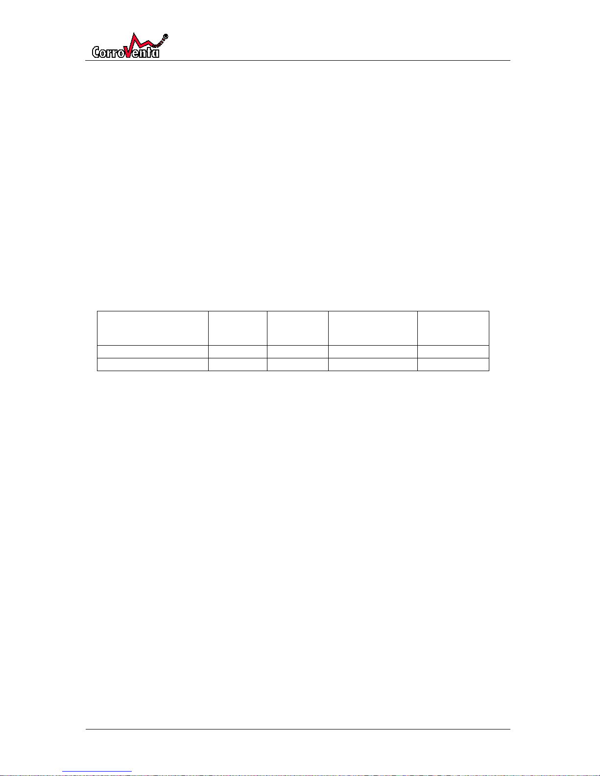
If the copy is opened with Excel the data can be sorted to columns resulting in the format presented
in the example below. The column ”Unit ID” gives the ID of the Control Unit to which the Control
Panel is connected. Log posts created while no Control Unit was connected will have ID zero (0).
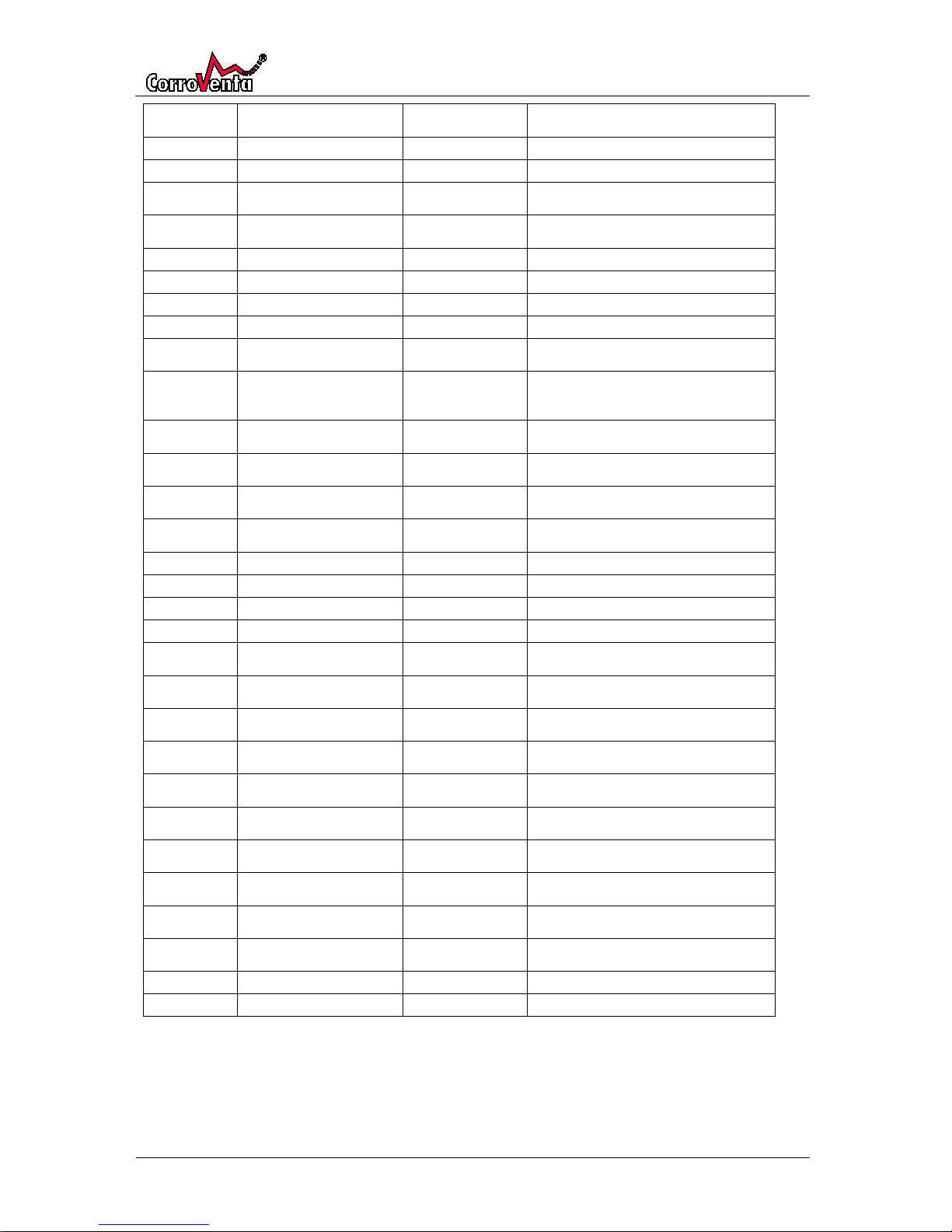
”PARAMETER NR” records the given parameters internal number, an information that normally is of
no importance to the user unless it is used to sort data or to search for information.”PARAMETER
NAME” is naturally the name of the parameter and ”PARAMETER VALUE” the given parameter’s
value at given time.
DATE/TIME
UNIT ID
PARAMETER
NR
PARAMETER
NAME
PARAMETER
VALUE
2011-01-01 00:01
730
101
D RHlow
-4
In the following, all the parameters that can appear in the log are presented.
Page 27
HomeVision® Pro/Lite
© Corroventa Avfuktning AB
Rev A
27 (30)
PARAMETER
NR
PARAMETER
NAME
PARAMETER
VALUE
DESCRIPTION
101
D RHlow
-4
Hysteresis Upper
102
D RHHigh
4
Hysteresis Lower
103
Calc Low RH
61
Calculated deactivation level for the
dehumidifier, Fixed control
104
Calc High RH
69
Calculated activation level for the
dehumidifier, Fixed control
106
MGI safety margin
-15
Safety margin, Mould Growth Index control
109
RH nominal fixed
65
Setpoint, Fixed control
110
RH alarm limit
10
Alarm limit
111
RH alarm level
69
Calculated alarm level, Fixed control
120
output FAN
1 Logged at time of automatic activations and
deactivations of fan. 1 at start. 0 at stop.
121
output HEATER
1
Logged at time of automatic activations and
deactivations of heater (dehumidifier). 1 at
start. 0 at stop.
122
Alarm 1 overheated
1
Normally 1. 0 when alarm is triggered –
displayed on the Control Panel.
123
Alarm 2 failure
1
Normally 1. 0 when alarm is triggered –
displayed on the Control Panel.
124
Alarm 3 humidity
1
Normally 1. 0 when alarm is triggered –
displayed on the Control Panel.
125
ContFan
1
Continuous Fan is 1. 0 for activation only
when dehumidifying.
126
FIX/MGI
0
0 for Fixed control. 1 for MGI..
127
Months to service
13
Starts at 13 and counts down.
128
Time changed
2011-05-03 15:33
Logged when time is changed.
130
CU ID
725
Logging of Control Unit ID.
132
Pairing attempt std/serv
0
Logged when the system tries to connect
new unit. 0 for Standard, 1 for service.
133
Alarm Connection lost
1
Normally 1. 0 when alarm is triggered –
displayed on the Control Panel.
134
Alarm USB writing error
1
Normally 1. 0 when alarm is triggered –
displayed on the Control Panel.
135
Alarm 4 CU failure
1
Normally 1. 0 when alarm is triggered –
displayed on the Control Panel.
142
Corrective action taken
1
Logged when an alarm or a service
reminder is acknowledged.
143
Lite/Pro
1
Logging of Control Panel version.
0 for Lite. 1 for Pro.
150
Active hrs this month
19
Logging of accumulated hours of operation.
Logged the last day of each month.
165
Mean temp this month
14
Logging of average temperature. Logged the
last day of each month.
180
RH this month
45
Logging of average relative humidity Logged
the last day of each month.
192
Active hrs/day
2,7
Logging of accumulated hours of operation.
Logged daily.
193
Mean temp/day
14
Logging of average temperature.
194 Mean RH/day 43
Logging of average relative humidity.
Page 28

HomeVision® Pro/Lite
© Corroventa Avfuktning AB
Rev A
28 (30)
Service and maintenance
HomeVision® requires neither periodic service nor any maintenance.
The battery power option of the Control Panel is intended for use only during the installation. As
soon as this is finished, the Control Panel should be powered by the included power adaptor and the
batteries should then be removed as many makes and types have a tendency to leak as they age. The
leakage from the batteries can cause the electronics of the HomeVision® to fail.
If the batteries still, for any reason, needs to be replaced they shall be 1.5V AAA cells. Two such
batteries are required.
Page 29
HomeVision® Pro/Lite
© Corroventa Avfuktning AB
Rev A
29 (30)
Fault finding
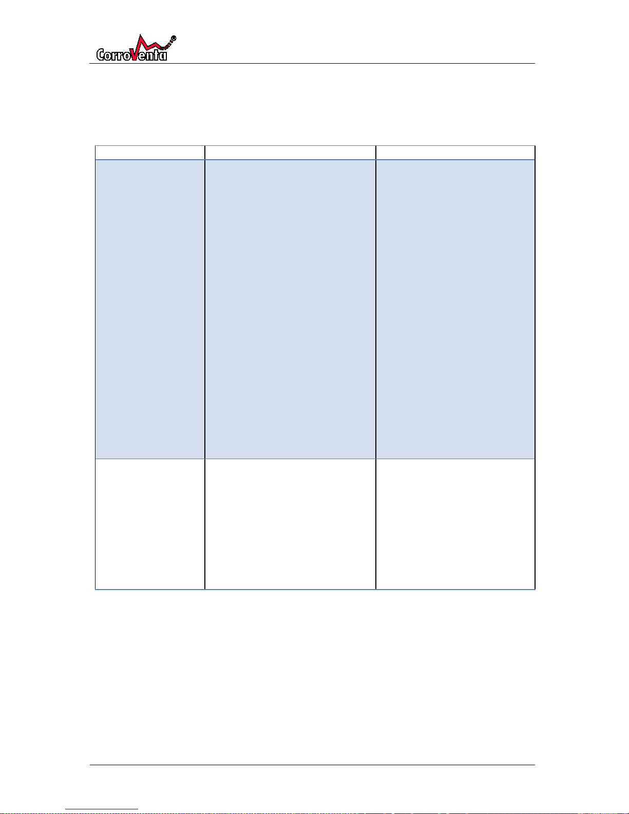
Note: The alarms and the warnings of the system are presented in previous chapter, including
instructions on how to address them. Many of them require the dehumidifier manual.
Symptom
Probable cause
Measure
The Control Panel
does not work.
The display does not
show anything
If batteries are used, these might be
empty.
The power adaptor is not connected
or broken.
Replace batteries.
Verify that the power adaptor is
connected to the power outlet
and that there is power in the
outlet (connect another consumer
to the outlet such as a lamp or a
radio)
Verify that the power connector
cable is correctly positioned in the
Control Panel.
If the problem remains, insert
batteries (1.5V AAA cells) in the
Control Panel. If this works, the
power adaptor is broken and
needs to be replaced.
If none of the above works, the
Control Panel itself is probably
out of order. Please contact your
retailer.
The Control Panel
does not log anything-
The USB stick can be malfunctioning
or, if used anywhere else before,
incorrectly formated.
Verify that the USB stick, if it has
been used anywhere else, is FAT
32 formated.
If this does not work, replace the
USB stick with another FAT32
formated stick.
If the problem remains, please
contact your retailer.
Page 30
HomeVision® Pro/Lite
© Corroventa Avfuktning AB
Rev A
30 (30)
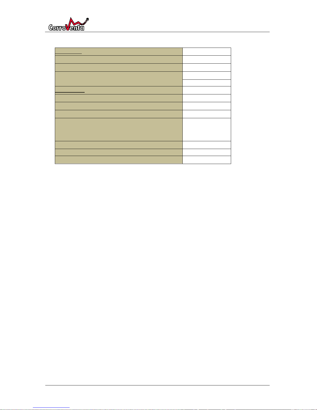
Technical data
Typ LAF 50 LAF 50E LAF 50E2 LAF 100 LAF 100E LAF 150 LAF 150E
Control Unit
Voltage (powered by dehumidifier)
24VDC
Protection class
IP 56
Length x Width x Height (mm)
180x110x63 mm
Control Panel
Battery type
AAA cell, 1,5 Volts
Power adaptor: Connection, Primary
230VAC/50Hz
Secondary voltage and max current
5VDC, 800mA
USB interface for memory stick
Delivered with 1GB
memory stick
Length x Width x Height (mm)
Radio Frequency
868 MHz
 Loading...