

CORRECT CRAFT Super Sport, Super Air Nautique Team Edition, Super Air, Nautique Super Sport, Pro AirNautique User Manual
...
i
Dear Correct Craft Owner:
Congratulations on your purchase of a Nautique Super Sport / Super Air
Nautique / Super Air Nautique Team Edition. You have chosen a boat that is
unequaled “on the waters of the world” for water-skiing and wakeboarding.
Since 1925, we have manufactured some of the finest products boat builders
can produce.
Your boat was manufactured with the latest marine technology and materials.
You have bought into a legacy handed down by W. C. Meloon over 77 years
ago. His dedication to building boats to the glory of God remains true today as
the cornerstone of our commitment in bringing to you the finest in water sports
boats. We continue to lead this industry in technology and design innovation.
Our heritage is a source of pride. Years of experience, including that of four
generations of Meloons have gone into the building of your boat. We hope
that you will enjoy it to the fullest.
Take a moment to review this owners manual for your boat. We have
assembled this manual to inform you about your boat and educate you further
on boating. There are many tips and tricks on care and maintenance sprinkled
throughout the manual, along with some cautions that will apply to your boat.
Boating is very important to us and we would like you to enjoy many years of
boating.
Welcome into the Nautique family.
Sincerely,
Walter N. Meloon
President/Chief Executive Officer
Trust in the Lord with all thine heart;
and lean not unto thine own understanding.
In all thy ways acknowledge him,
and he shall direct thy paths.
Proverbs 3: 5-6

ii
T
ABLE OF C ONTENTS
Chapter 1. Overview ........................................
Chapter.Page
Dash Pod and Console Layout ...................................1.1
Specifications..............................................................1.1
Keyless Ignition and Serial Switching .......................1.2
Multiple Keyless Ignition Codes................................1.3
Primary User Code................................ .....................1.3
Erasing the User Codes ..............................................1.4
Key Functions.............................................................1.5
Dash Pod Switches .....................................................1.5
Bilge Pump .................................................................1.6
Bilge Pump Only Mode..............................................1.6
Navigation Lights ......................................................1.7
Anchor ........................................................................1.7
Ventilation Blower.......................................................1.7
12 Volt Plug ...............................................................1.7
Engine and V-Drive Warning Light ..........................1.7
Gauges ........................................................................1.7
Emergency Cut-off Switch ........................................1.8
Throttle .......................................................................1.8
Pylon...........................................................................1.9
Lifting rings ...............................................................1.10
Capacity Plate ...........................................................1.10
Hull Identification Number .......................................1.11
Driver’s Seat Adjustment ..........................................1.12
Ski Locker Latch.........................................................1.12
Fueling .......................................................................1.12
Engine Hatch and Storage .........................................1.12
Manual Latch Release in Trunk .................................1.13
Engine Cooling Water Intake Shut-off Valve.............1.13
Stern Seat....................................................................1.13
Love Seat/Love Seat Extension .................................1.13
Walk Through Windshield..........................................1.14
Dash Cooler ................................................................1.14
Bow Cooler ................................................................1.14
Fuel Tank Location ....................................................1.14
Boarding Platform Removal.......................................1.14
Battery Location .........................................................1.14
Optional Electric Sensor in Drainplug .......................1.14
Flight Clips .................................................................1.14
Optional Flight Control Tower (folding)....................1.15
Optional Launch Control System...............................1.15
Winterizing Launch Control System..........................1.15
Correct Craft Cruise ...................................................1.16
Speedometer ...............................................................1.17
Tachometer .................................................................1.19

iii
Chapter 2. Engine Overview
Engine Check List ......................................................2.1
Fuel Injected Engine Does Not Start..........................2.3
Flooded Engine...........................................................2.3
Break In Procedure.....................................................2.4
General Notes .............................................................2.5
Chapter 3. Cautions and Warning Labels.................3.1
Chapter 4. Boat Handling /Safety Regulations........
4.1
Chapter 5. Boat Care
Bilge Pump ................................................................5.1
Propeller ....................................................................5.2
Stuffing Box ...............................................................5.4
Quick Drain Oil ..........................................................5.4
Salt Water Boating......................................................5.5
Battery Maintenance...................................................5.5
Winterizing Your Boat ................................................5.6
Gelcoat Care ...............................................................5.7
Teak Care....................................................................5.7
Glass Care...................................................................5.8
Metal Care ..................................................................5.8
Vinyl Care...................................................................5.9
Tunable Rudder...........................................................5.10
Chapter 6. Trailering
Hitching ......................................................................6.1
Security.......................................................................6.1
Towing Your Boat.......................................................6.1
Wiring.........................................................................6.1
Long Trips ..................................................................6.2
Chapter 7. Warranty and Owner Responsibility.......7.1
Chapter 8. Engine Maintenance
PCM Delivery Inspection...........................................8.1
Changing the Engine Oil............................................8.3
Engine Crankcase Capacity/Level............................8.4

iv
Chapter 8. Engine Maintenance
Checking / Adding V-Drive Oil..................................8.5
V-Drive Low Oil Pressure Warning............................8.5
Changing V-Drive Oil.................................................8.6
Winterizing V-Drive Unit............................................8.6
Water Strainer..............................................................8.6
Transmission Cooler....................................................8.7
Replacing the Fuel Filter.............................................8.7
Prolonged Storage .....................................................8.7
Exhaust System .........................................................8.8
Maintaining Transmission Fluid Level ......................8.8
Adjusting the Water Pump Belt (Ford Only) .............8.9
Alternator Drive Belt Tension....................................8.9
Fuel Pumps .................................................................8.9
Fuel Control Cell ........................................................8.10
Battery .......................................................................8.11
Fuel ............................................................................8.12
Engine Circuit Breakers on EFI Engines ...................8.12
Cooling System ........................................................8.13
Fresh Water Cooling ..................................................8.14
Checking Coolant Level ............................................8.14
Winterization Instructions ..........................................8.15
Winter Storage of Batteries ........................................8.18
Recommissioning .......................................................8.18
Flushing Instruction....................................................8.19
Engine Maintenance Scheduled .................................8.21
Engine Troubleshooting..............................................8.23
Engine Specifications .................................................8.25
Chapter 9. Service Records & Order Forms
Change of Ownership.................................................9.1
Problem Notification Form ........................................9.2
Warranty Transfer .......................................................9.3
Warranty Transfer Application ...................................9.4
Nautique Service Center Locations............................9.7
Nautique Friend Program ...........................................9.6
NOA Membership Form ............................................9.8
Warranty Transfer Request .........................................910
Dash Plaque Request Form.........................................9.11
Glossary ......................................................................9.12

Chapter 1
O VERVIEW
Specifications Nautique Super Sport / Super Air
Nautique / Super Air Nautique Team Edition
100 % Fiberglass Construction
Length without Platform. . . . . . . . . . . 21' 2” . . . . . (6.45 m)
Length with Platform . . . . . . . . . . . . . 22'6" . . . . . . (6.86 m)
Beam . . . . . . . . . . . . . . . . . . . . . . . . . 91" . . . . . . . (2.31 m)
Draft . . . . . . . . . . . . . . . . . . . . . . . . . 28" . . . . . . . (0.71 m)
Fuel Tank Capacity . . . . . . . . . . . . . . 39 Gallons. . (148 ltr)
Approx. Weight . . . . . . . . . . . . . . . . . . 3190 lbs. . . (1450 kg)
Approx. Weight with full LCS . . . . . . . 4010 lbs. . . (1825 kg)
Max Capacity. . . . . . . . . . . . . . . . . . . 10 people/1450 lbs .
. . . . . . . . . . . . . . . . . . . . . . . . . . . . . (660 kg)
Lifting Rings (dist.. between centers) . 20' . . . . . . . . (6.1 m)
Welcome to the Nautique family.
We realize you may be anxious to get your boat in the water. This manual has
been written to familiarize and educate you about your boat so you will be
more comfortable out on the water. Your boat is built to provide you with the
finest watersports boat in the world. Whether you are skiing, wakeboarding or
cruising, we trust you and your family will enjoy this boat for many years.
Let’s start by taking a look at the dash pod and console to familiarize yourself
with the locations of the gauges and switches.
Dash Pod and Console Layout
Standard equipment on your boat
are the following gauges: oil
pressure, engine coolant
temperature, speedometer,
tachometer/ hour meter, fuel level,
voltage. Optional equipment
gauges available include: air/water
temp gauge, clock, depthfinder,
Launch Control System tank
gauges, remote stereo control and
Correct Craft Cruise or Perfect
Pass Pro speed control. The
optional gauges are positioned on
1.1
Dash Pod
the console located to the right of the drivers knee or on the two raised
surfaces in the center of the dash pod.
CAUTION: The keypad and switch control box will be damaged beyond repair if
the boat battery cables or the main power leads to the keypad and switch
controlbox are reversed. Be sure to use caution and avoid reversing these
connections.
Keyless Ignition and Serial Switching
The ignition switch system is keyless and has three modes of operation.
Locked Mode
When the boat battery is first connected, the unit is in locked mode. In this
mode, the horn, bilge pump, bilge blower, and code buttons are operational.
Unlocked Mode
Unlocked mode is entered after the user successfully enters the user code,
presses, and releases the start button. When the code keys are pressed, the
system indicator light to the right of the start button will turn on while the
key is pressed down. This indicates the button has actually been pushed.
When the system is unlocked, power is supplied to the boat and the system
indicator light will turn on. At this point all keypad buttons are operational
and actuating these buttons will control the corresponding boat functions. To
put the unit back in locked mode, the user must successfully enter the user
code then
press the
stop button.
When the
code keys
are pressed,
the system
indicator
light to the
right of the
start button
will turn off
while the
keys are
pressed
down. Power will be cut to all of the accessories with the exception of the
horn, bilge pump, bilge blower and code buttons.
Run Mode
First enter the unlocked mode.
1.2
Keyless Ignition

Pressing and releasing the start button quickly will put the unit in run mode.
When this is done, power is supplied to the engine ignition,but the engine will
not crank and the ignition indicator light just left of the start button is turned
on. If the start button is not pressed again within 15 minutes the unit will exit
run mode by shutting off power to the ignition and re-enter unlocked mode. If
the user presses and holds the start button, power is supplied to the ignition and
starter for as long as the user holds the start button down. All accessory
buttons are operational in this mode as well. Pressing the stop button will shut
off the engine and the unit is then put back in unlocked mode.
After the engine starts, release the start button.
Automatic Reversion to Locked Mode
If no keypad activity takes place for ten hours after unlocking, the system will
automatically revert to the locked mode. This helps to minimize battery drain.
Automatic Back-lighting
Pressing any keypad button will automatically turn the keypad back-lighting
on for ten seconds. This feature is useful for those that use their boat after dark
to find the appropriate keypad buttons.
Multiple Keyless Ignition Codes
The keyless ignition system has provision for three different ignition codes.
Any of the three codes may be used to unlock or lock the system.
The “Master Embedded Code” is programmed into the system at Correct Craft
Inc. and is not changeable, remaining with the boat for it’s life. This code can
be used to unlock the system, to lock the system and to erase the two user
codes.
The “Primary User Code” is programmed into the system by the owner with
the dealers help at the time of boat delivery. This code is used to unlock the
system, to lock the system, and to add or change the “Secondary User Code”
The “Secondary User Code” is programmed into the system by the owner
when necessary. This code is only used to unlock or lock the system. The
“Secondary User Code” is excellent to use for limited access to the boat.
Programming and/or Changing Primary or Secondary User Code
Note: To help prevent battery drain, when you are finished using the boat
make sure you STOP the engine and LOCK the PME ignition system. (two
steps)
Note: The “System Indicator Light” is on the ignition keypad below the
number four (4). The “Ignition Indicator Light” is also on the keypad below
the number one (1)
1.3

Programming the Primary User Code
Make sure that the system indicator light is off and the "Master Embedded
Code" has been entered. Until a primary user code is set, the keyless ignition
will behave as follows. Pressing start once will unlock the system while
pressing it a second time will start the engine. Pressing stop once will turn off
the engine while pressing it a second time will lock the system.
To program the primary user code, press buttons one and four at the same time,
putting the system in code programming mode. The system indicator light will
be flashing.
Enter a code from two to eight characters long and press start. For verification,
re-enter the code and press start again. The system indicator light should stop
flashing and stay on. If the light does not stop flashing, press stop and begin
again.
To lock the system re-enter either the primary user code or the master
embedded code and press stop.
Changing the Primary User Code
NOTE: The current primary code must be used to change to another primary
code.
Make sure that the system indicator light is off. Enter the primary user code
then press buttons one and four at the same time. This puts the system in code
programming mode. The system indicator light will be flashing.
Enter a code from two to eight characters long and press start. For verification,
re-enter the code and press start again. The system indicator light should stop
flashing and stay on. If the light does not stop flashing, press stop and begin
again.
To lock the system re-enter either the new primary user code or the master
embedded code and press stop. Please note, changing the primary code will
erase the secondary user code. The secondary code will need to be re-entered.
Programming or Changing the Secondary User Code
NOTE: The secondary code will only lock or unlock the system & can not be
used for any reprogramming
Make sure that the system indicator light is off. Enter the primary user code
and press buttons one and three at the same time putting the system in code
programming mode. The system indicator light will be flashing.
Enter a code from two to eight characters long and press start. Re-enter the
code and press start again. The system indicator light should stop flashing and
stay on. If the light does not stop flashing, press stop and begin again.
To lock the system re-enter any of the three codes and press stop.
1.4
Erasing the User Codes
Make sure the system indicator light is off. Enter the master embedded code
and press buttons one and three at the same time. This will erase the system
user codes.
The keyless ignition will now behave as if there are no codes in memory.
Pressing the start button will unlock the system and pressing the stop button
will lock it without entering a code. To program a primary user code, make
sure the system indicator light is off and press buttons one and four at the same
time. This puts the system in code programming mode. The system indicator
light will be flashing. Follow the last two steps above to complete
programming the primary user code.
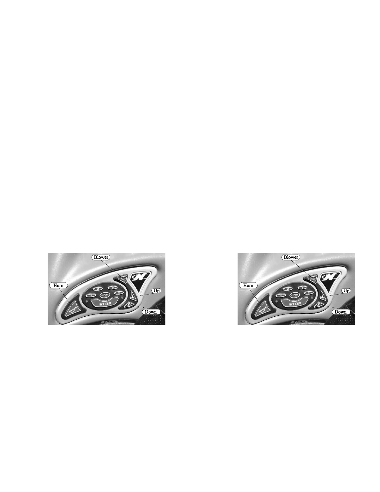
Key Functions
All keys with the exception of the bilge blower, bilge pump, horn, and the code
keys operate in unlocked or run mode. The horn, up, down, and start buttons,
(when starting the engine), are momentary buttons. All others require a press
to turn on and another press to turn off.
Exceptions
Pressing the heater button will actuate the heater in the following sequence:
Heater off (low(medium(high(back to off)
Pressing the LCS fill or drain will toggle the power to the corresponding
function. Turning either the fill or the drain on will automatically turn the
other off.
The navigation light button always controls the anchor light and if the
navigation lights are on, the anchor light button will have no affect. If the
navigation lights are off, the anchor light button will turn only the anchor light
on and off. One special feature works when the anchor lights are on. If the
user desires to turn the navigation lights on, it is unnecessary to turn the anchor
lights off. Simply pressing the navigation light button will leave the anchor
light on and turn on the bow light.
Dash Pod Switches
There are function
key switches to the
right of the helm
and surrounding the
keyless ignition
keypad. These are
waterproof
momentary
switches. By
pressing a function
1.5
Function Keys
Erasing the User Codes
Make sure the system indicator light is off. Enter the master embedded code
and press buttons one and three at the same time. This will erase the system
user codes.
The keyless ignition will now behave as if there are no codes in memory.
Pressing the start button will unlock the system and pressing the stop button
will lock it without entering a code. To program a primary user code, make
sure the system indicator light is off and press buttons one and four at the same
time. This puts the system in code programming mode. The system indicator
light will be flashing. Follow the last two steps above to complete
programming the primary user code.
Key Functions
All keys with the exception of the bilge blower, bilge pump, horn, and the code
keys operate in unlocked or run mode. The horn, up, down, and start buttons,
(when starting the engine), are momentary buttons. All others require a press
to turn on and another press to turn off.
Exceptions
Pressing the heater button will actuate the heater in the following sequence:
Heater off (low(medium(high(back to off)
Pressing the LCS fill or drain will toggle the power to the corresponding
function. Turning either the fill or the drain on will automatically turn the
other off.
The navigation light button always controls the anchor light and if the
navigation lights are on, the anchor light button will have no affect. If the
navigation lights are off, the anchor light button will turn only the anchor light
on and off. One special feature works when the anchor lights are on. If the
user desires to turn the navigation lights on, it is unnecessary to turn the anchor
lights off. Simply pressing the navigation light button will leave the anchor
light on and turn on the bow light.
Dash Pod Switches
There are function
key switches to the
right of the helm
and surrounding the
keyless ignition
keypad. These are
waterproof
momentary
switches. By
pressing a function
1.5
Function Keys
key, you activate the function indicated.
All of these switches interface with a sealed circuit breaker box located under
the bow. The circuit breaker box consists of sixteen soft opaque flexible vinyl
tubular shields which cover sixteen circuit switches. When the circuits are
functioning, the tubular shield is somewhat flexible. A tripped circuit breaker
will extend and fill the tubular shield, causing it to be inflexible. To locate a
tripped circuit breaker, run your fingers over the two rows of switches and
locate the switch shield that has become inflexible. To re-set, simply press in
the extended circuit switch shield.
Bilge pumps
The bilge pump switch turns on the bilge pumps. There is a bilge pump down
by the front of the fuel tank and another bilge pump back by the rudder. When
you push the bilge pump key on the keypad, both
pumps will come on and run for several moments
to “sense” of there is water in the bilge. If there
is water in the bilge, they will remain on until the
water is pumped out. If there is no water in the
bilge, they will turn off. If you want immediate
pump action, turn the switch off and then back on
again. The pumps will turn on periodically to
determine if there is water in the bilge. If so, they
will remain on until the water is pumped out.
Note: The “Bilge” switch must be turned on
for this feature to operate. This will not drain
significant power from the battery unless the bilge pumps are required to
run frequently because of a leak or excessive rainwater. This pumping
system should not be relied on over an extended period of time. We
suggest you frequently inspect your boat.
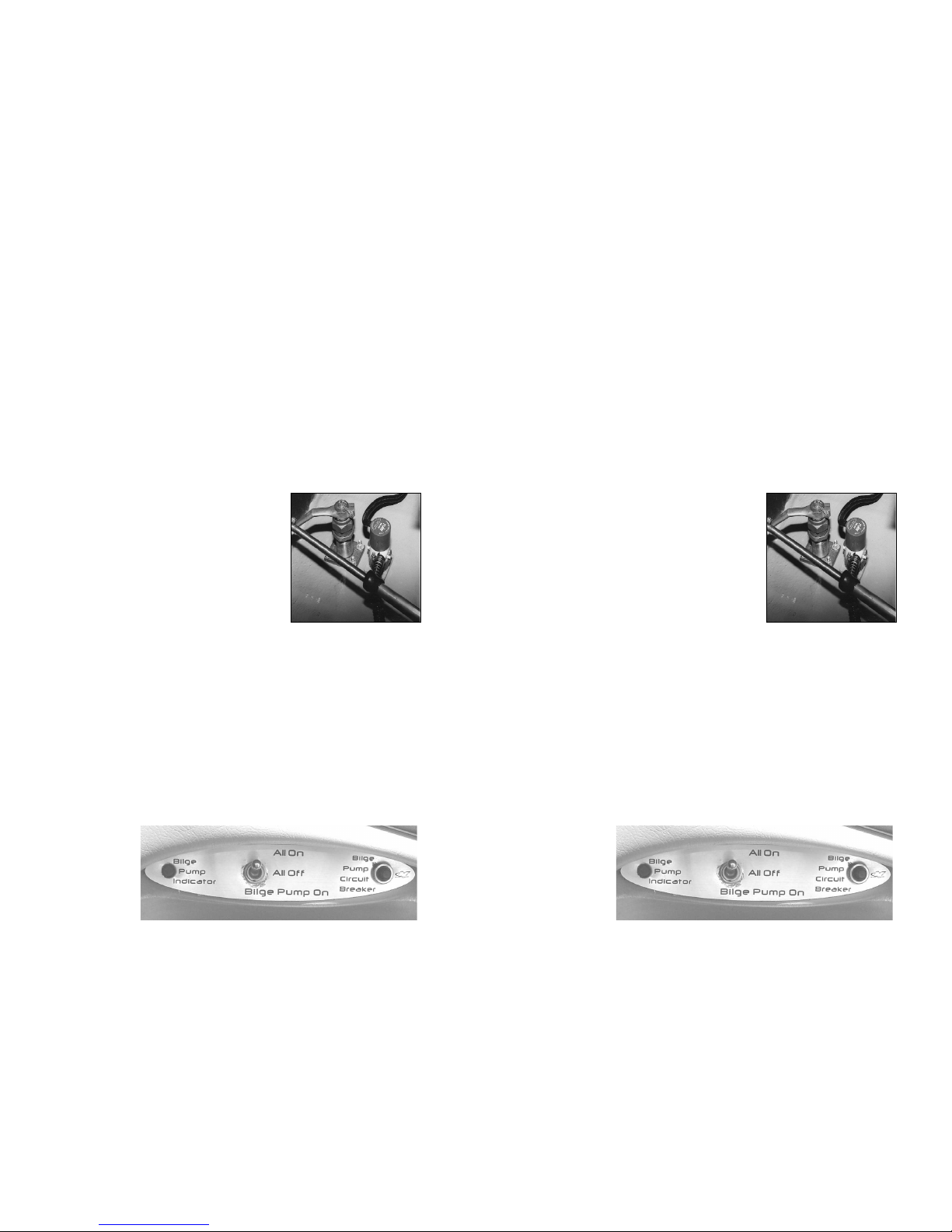
Bilge Pump Only Mode
This feature is activated by a switch located below the gauges on the side
console. The switch has three positions, on, off and bilge. If the boat is going
to sit for more than a few days with the bilge pump on, it is important that the
switch is set in
the “bilge”
position to
minimize battery
drain. This will
activate the bilge
pump and shut off
power to the
Serial Switching
1.61.6
Bilge Pump
PME Bypass
key, you activate the function indicated.
All of these switches interface with a sealed circuit breaker box located under
the bow. The circuit breaker box consists of sixteen soft opaque flexible vinyl
tubular shields which cover sixteen circuit switches. When the circuits are
functioning, the tubular shield is somewhat flexible. A tripped circuit breaker
will extend and fill the tubular shield, causing it to be inflexible. To locate a
tripped circuit breaker, run your fingers over the two rows of switches and
locate the switch shield that has become inflexible. To re-set, simply press in
the extended circuit switch shield.
Bilge pumps
The bilge pump switch turns on the bilge pumps. There is a bilge pump down
by the front of the fuel tank and another bilge pump back by the rudder. When
you push the bilge pump key on the keypad, both
pumps will come on and run for several moments
to “sense” of there is water in the bilge. If there
is water in the bilge, they will remain on until the
water is pumped out. If there is no water in the
bilge, they will turn off. If you want immediate
pump action, turn the switch off and then back on
again. The pumps will turn on periodically to
determine if there is water in the bilge. If so, they
will remain on until the water is pumped out.
Note: The “Bilge” switch must be turned on
for this feature to operate. This will not drain
significant power from the battery unless the bilge pumps are required to
run frequently because of a leak or excessive rainwater. This pumping
system should not be relied on over an extended period of time. We
suggest you frequently inspect your boat.
Bilge Pump Only Mode
This feature is activated by a switch located below the gauges on the side
console. The switch has three positions, on, off and bilge. If the boat is going
to sit for more than a few days with the bilge pump on, it is important that the
switch is set in
the “bilge”
position to
minimize battery
drain. This will
activate the bilge
pump and shut off
power to the
Serial Switching
1.61.6
Bilge Pump
PME Bypass

and Keyless Ignition System. It is important to remember that the engine or
other accessories can not be used unless the switch is in the “on” position.
Located with the switch is a circuit breaker and indicator light for the bilge
pump. The circuit breaker is only active when the switch is in the “bilge”
position. The indicator light will come on anytime the bilge pump is activated.
Navigation Lights
This switch controls the navigation lights. The law requires the bow light and
the 360 degree light (located at the transom) be turned on while running the
boat after sunset or before dawn.
Anchor
This switch turns on the 360 degree light. Insert this light pole into the
receptacle located on the transom and push the anchor switch on the pod to
turn this light on. This light is required by law to be on after sunset and before
dawn when the boat is not moving.
Accessories
There is an accessory button provided that controls power to a yellow wire
coiled up near the controlbox. Power to this wire is protected by a 10-amp
circuit breaker. Attaching an accessory to this wire should be done by
someone knowledgeable in DC electrical wiring.
Ventilation Blower
This switch turns on the blower in the bilge. This blower must be turned on
for four (4) minutes prior to engine ignition and also at anytime when the boat
is operated at slow speeds.
12 Volt Plug
These plugs can be utilized to power cellular phones, video cameras or various
other electronics. These plugs are powered through a ten (10) amp breaker.
Engine Warning Light
This light is in the center of the dash pod between the speedometer and the
tachometer and indicates high engine temperature.
V-Drive Warning Light
This light is below the main gauges and indicates low V-Drive oil pressure.
Horn This is a momentary switch.
Gauges
• Volt
This gauge tells you how many volts the alternator is producing. During
normal running, it should read 13-14 volts. Running a heater, shower or
stereo amplifier will draw power from the alternator and possibly drop
voltage below normal. If this occurs, the battery will not charge correctly.
1.7
• Temp This tells you the temperature of the coolant in the engine.
• Oil Pressure This gauge tells you the engine oil pressure.
• Tachometer / Hour Meter This gauge indicates the revolutions per minute the
engine is turning, and the total accumulated engine hours. The tachometer /
hour meter has a digital and analog readout. Mode selection is made by
pressing the mode keypad.
• Speedometer Your Nautique is equipped with an electronic speedometer by
Teleflex. This instrument is different in many ways. It is capable of being
programmed for multiple functions. This speedometer can be calibrated. To
access the various functions, press and scroll through the Mode Key. To
change the mode, press the INCREASE or DECREASE key. For a detailed
analysis of your speedometer, refer to the Teleflex speedometer section at the
end of this chapter.
• Emergency Cut-off Switch There is an emergency cut-off switch for the
protection of you and your passengers. The clip at the end of the cord must
be attached securely to the driver. Check the system by attaching the clip to
the switch, start the boat and then pull the clip off the switch. The engine
should stop. UNDER NO CIRCUMSTANCES SHOULD YOU OPERATE
THE BOAT IF THIS SYSTEM DOES NOT FUNCTION PROPERLY. If it
does not function correctly, contact your Correct Craft dealer to have the
problem corrected.
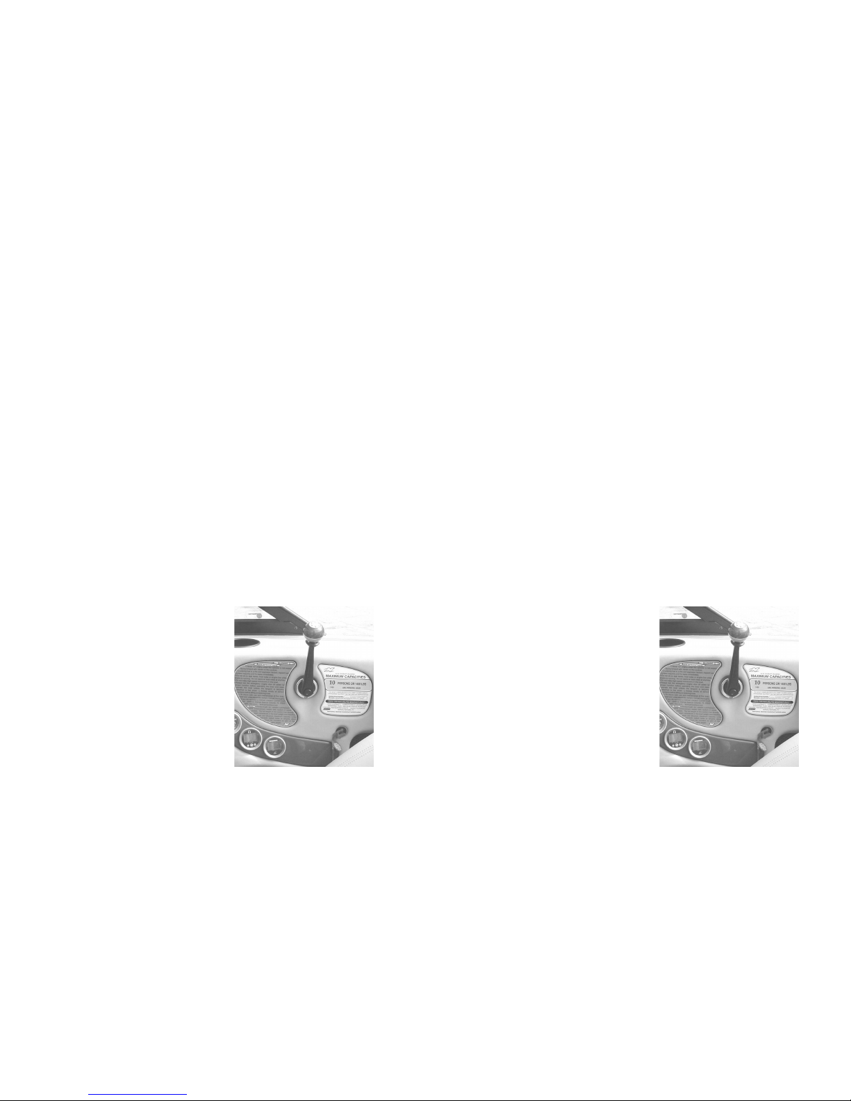
• Throttle The throttle control consists of the throttle lever, a lock out ring and
a neutral button. The neutral button is a push-button at the bottom of the
throttle lever which allows the throttle to
be advanced without the transmission
being engaged. The throttle lever must be
in the neutral position to start the engine.
The throttle arm has three detent positions.
Note: When in a detent position the throttle
arm will resist movement, but can be
moved with sufficient pressure. Neutral
detent is straight up. Forward detent is
approximately 30 degrees toward the bow,
and reverse detent is approximately 30
degrees toward the stern. Moving the
throttle from neutral detent to either
forward or reverse detent will shift the boat
into that gear. The engine will remain at idle speed.
To increase (forward or reverse) engine speed and therefore boat speed,
continue to rotate the throttle arm past the detent.
Note: When shifting out of neutral, it is best to pause in the appropriate detent
1.8
Throttle
• Temp This tells you the temperature of the coolant in the engine.
• Oil Pressure This gauge tells you the engine oil pressure.
• Tachometer / Hour Meter This gauge indicates the revolutions per minute the
engine is turning, and the total accumulated engine hours. The tachometer /
hour meter has a digital and analog readout. Mode selection is made by
pressing the mode keypad.
• Speedometer Your Nautique is equipped with an electronic speedometer by
Teleflex. This instrument is different in many ways. It is capable of being
programmed for multiple functions. This speedometer can be calibrated. To
access the various functions, press and scroll through the Mode Key. To
change the mode, press the INCREASE or DECREASE key. For a detailed
analysis of your speedometer, refer to the Teleflex speedometer section at the
end of this chapter.
• Emergency Cut-off Switch There is an emergency cut-off switch for the
protection of you and your passengers. The clip at the end of the cord must
be attached securely to the driver. Check the system by attaching the clip to
the switch, start the boat and then pull the clip off the switch. The engine
should stop. UNDER NO CIRCUMSTANCES SHOULD YOU OPERATE
THE BOAT IF THIS SYSTEM DOES NOT FUNCTION PROPERLY. If it
does not function correctly, contact your Correct Craft dealer to have the
problem corrected.
• Throttle The throttle control consists of the throttle lever, a lock out ring and
a neutral button. The neutral button is a push-button at the bottom of the
throttle lever which allows the throttle to
be advanced without the transmission
being engaged. The throttle lever must be
in the neutral position to start the engine.
The throttle arm has three detent positions.
Note: When in a detent position the throttle
arm will resist movement, but can be
moved with sufficient pressure. Neutral
detent is straight up. Forward detent is
approximately 30 degrees toward the bow,
and reverse detent is approximately 30
degrees toward the stern. Moving the
throttle from neutral detent to either
forward or reverse detent will shift the boat
into that gear. The engine will remain at idle speed.
To increase (forward or reverse) engine speed and therefore boat speed,
continue to rotate the throttle arm past the detent.
Note: When shifting out of neutral, it is best to pause in the appropriate detent
1.8
Throttle

before applying additional throttle.
The lockout ring mechanism prevents unintentional shifting into forward or
reverse. To operate the throttle lever, you must lift the lockout ring. DO NOT
shift quickly from forward into reverse. Stay in the neutral position until
the boat has lost speed before shifting into reverse. Shifting should not be
attempted above 1200 RPM except in emergency situations.
CAUTION: LOADING AND UNLOADING OF PASSENGERS FROM
A DOCK OR FROM THE WATER SHOULD ONLY BE DONE AFTER
THE ENGINE HAS BEEN TURNED OFF.
Pylon
The ski pylon is manufactured from high strength aluminum alloy that is
engineered for durability. It is hard coat anodized and impregnated with a
PTFE (teflon) material. If the pylon becomes loose, stop using the pylon and
take the boat to your Correct Craft dealer for service.
PYLON--WARNING/CAUTION--AVOID PERSONAL INJURY. THIS WATER
SKI PYLON WAS DESIGNED FOR WATER SKIING ONLY. ANY OTHER
USES, SUCH AS PARASAILING, KITE FLYING, TOWING OTHER BOATS
AND/OR USING AN EXTENDED PYLON, ECT., MAY OVERSTRESS THE
PYLON POSSIBLY CAUSING PERSONAL INJURY AND/OR EQUIPMENT
DAMAGE. DO NOT SIT BEHIND (AFT) THE TOW PYLON WHEN TOWING
SKIERS.
CAUTION: ALTHOUGH THE EXTENDED PYLON AND BAREFOOT
BOOMS HAVE BECOME POPULAR ADDITIONS TO MANY TOURNAMENT
INBOARDS, CORRECT CRAFT STRONGLY OBJECTS AND OPPOSES THE
USE OF ANY PYLON EXTENSION WHETHER UP OR TO THE SIDE OF
ANY OF IT’S PRODUCTS. THE USE OF PYLON EXTENSIONS CAN ALTER
THE HANDLING CHARACTERISTICS OF THE BOAT, POSSIBLY
RESULTING IN DANGEROUS INSTABILITY, WHICH COULD THEN LEAD
TO LOSS OF CONTROL; A SITUATION WHICH COULD CAUSE SERIOUS
OR FATAL INJURY TO THE BOAT DRIVER, PASSENGER(S), PERSON(S)
BEING TOWED, AND ANYONE ELSE WHO MIGHT BE IN THE VICINITY
OF SUCH A MISHAP.
CAUTION: CORRECT CRAFT DOES NOT APPROVE OF ANY
STRUCTURAL CHANGES, ADDITIONS OR MODIFICATIONS TO OUR
PRODUCTS. ANY TIME A DEALER OR CONSUMER MAKES A
CHANGE(S) TO OUR PRODUCT, THEY DO SO AT THEIR OWN RISK AND
SOLE LIABILITY. CORRECT CRAFT, INC. WILL NOT BE HELD LIABLE
FOR UNAUTHORIZED CHANGES, WHETHER DELETIONS OR
ADDITIONS, TO THE ORIGINAL EQUIPMENT / PRODUCT
MANUFACTURED AND SOLD BY CORRECT CRAFT, INC., EVEN IF SUCH
CHANGES, ADDITIONS, ECT. ARE MADE BY AN “AUTHORIZED”
DEALER, CUSTOMER, PROMOTIONAL REPRESENTATIVE OR ANY
OTHER PERSON, KNOWN OR UNKNOWN TO CORRECT CRAFT, INC.
1.9

Lifting rings
Your boat has lifting rings at the bow and at the stern. The lifting ring at the
bow is flush with the deck. To use this ring, lift up on the ring and insert the
lifting hook. These are designed to lift your boat in a steady and secure manner.
Be certain to use a winch that has a lifting capacity sufficient for your boat. See
boat weight specs in the front of this manual. These weights are dry weight.
You must add the weight of the battery, fuel, and gear to the dry weight.
CAUTION: DRAIN THE BILGE AND/OR LAUNCH CONTROL
SYSTEM AND/OR AFTERMARKET WATER BLADDERS(S) TO
ELIMINATE EXCESS WATER BEFORE YOU LIFT THE BOAT.
Note: Only use a hook that will pass easily through the lifting ring without
binding. This is very important. A hook that is too large or off-center could
break the lifting ring.
Capacity Plate
The capacity plate is used by boat manufacturers participating in the
National Marine Manufacturers
Association certification program.
Correct Craft has submitted your
model for inspection and
compliance with their guidelines.
The capacity plate has the
following information permanently
printed on it. It is attached to the
boat by the throttle for the operator
to read before they drive the boat.
• The total weight of persons, gear
and other items which the boat is
capable of carrying under normal
conditions. This weight must
include any water added to
ballast other than the Launch
Control System.
• The maximum number of persons allowed on the boat.
This information on the capacity plate applies under normal conditions and
special care must be used in any other than normal conditions.
Check the capacity plate on your boat and abide by these limits.
NOTE: CORRECT CRAFT, INC. INSTALLS A PERMANENT
WAKE ENHANCEMENT BALLAST TANK SYSTEM IN SOME
MODELS. THE FULL WEIGHT OF THIS SYSTEM HAS
ALREADY BEEN CONSIDERED IN THE BOAT WEIGHT AND
THEREFORE DOES NOT INFLUENCE MAXIMUM CAPACITY,
UNLIKE PORTABLE BALLAST TANKS OR WEIGHTS, WHICH
MUST BE INCLUDED AS PART OF THE GEAR WEIGHT.
CAUTION: A FULLY LOADED NAUTIQUE WILL HANDLE
DIFFERENTLY THAN A LIGHTLY LOADED ONE. DRIVE AND
1.10
Capacity Plate

TURN YOUR NAUTIQUE WITH THIS IN MIND. AS
WAKEBOARDING HAS DEVELOPED, WE HAVE WITNESSED
THE ADVENT OF BALLAST SYSTEMS WHICH ADD WEIGHT
AND INCREASE THE SIZE OF THE WAKE. THE SIMPLEST
BALLAST SYSTEM ON THE MARKET IS THE WATER BALLAST
TYPE, SUCH AS THE ‘LAUNCH PAD”. IT IS NOT UNCOMMON
TO SEE OPERATORS USE SUCH SYSTEMS AND THEN PUT
ADDITIONAL PEOPLE IN THEIR BOAT. PLEASE BE ADVISED
THAT THIS PRACTICE CAN LEAD TO OVERLOADING OF
YOUR BOAT. EACH CORRECT CRAFT, INC. BOAT HAS A
REQUIRED CAPACITY LABEL THAT MEETS THE MAXIMUM
WEIGHT OF PEOPLE, GEAR, AND BALLAST THAT CAN BE
PLACED IN THE BOAT. ALWAYS BE AWARE OF THE LOAD IN
YOUR BOAT AND DO NOT LOAD THE BOAT IN EXCESS OF
THE LISTED CAPACITY. THE QUEST FOR THE “PHATTEST”
WAKE HAS CAUSED SOME TO EXCESSIVELY OVERLOAD
THEIR BOATS. THIS MAY ADVERSELY AFFECT THE
OPERATION OF THE BOAT, POSSIBLY RESULTING IN INJURY
TO PERSONS INSIDE AND/OR OUTSIDE OF THE BOAT. AVOID
PERSONAL INJURY. DO NOT OVERLOAD YOUR NAUTIQUE.
GREAT CAUTION SHOULD BE EXERCISED WHEN COMING
OFF PLANE WITH A FULLY LOADED BOAT TO PREVENT THE
STERN ROLLER FROM COMING OVER THE TRANSOM INTO
THE VENTS LOCATED ON THE TRANSOM THAT COULD
CAUSE WATER INTRUSION INTO THE ENGINE
COMPARTMENT OR STORAGE AREAS.
Hull Identification Number
The hull identification number is a requirement of the U.S. Coast Guard for
boat manufacturers. It is a standardized numbering system that assigns a
specific sequence of numbers and letters to a specific boat. This number is
molded into the hull. You will find it on the right-hand side of the transom just
below the rubrail. Write this number down in your records and keep it in a safe
place away from the boat.
Here is a brief explanation to help you understand the hull number:
The first three digits represent Correct Craft, Inc.(CTC). The next five digits
are the boat’s serial number. The following digit is a letter from “A” through
“L” designating the month the boat was made.
There are three remaining numbers. The first of these represent the last digit of
the year the boat was built. The final two numbers state the MODEL year. A
boat built in July of 2001 is actually a 2002 model boat.
1.11

Driver’s Seat Adjustment
There is a lever under the driver’s seat
on the left side that allows the seat to
slide.
Ski Locker Latch
Push down on the raised portion of the
latch and the handle of the latch will pop
up. Lift the ski locker door with this
handle. Due to various environmental
conditions, equipment and other items
should not be left in storage
compartments for a long time. All
storage compartments that get wet or
damp should be left open to the air to
dry.
Fueling
There is a fuel fill on the port and
starboard side for added convenience.
Remove the slotted fuel fill cap to put
gas in the boat. There is a special “key”
for this cap. Use caution when fueling
your boat. Never fuel your boat
unattended. Use care to avoid being
splashed by fuel, or spilling fuel.
Engine Hatch and Storage
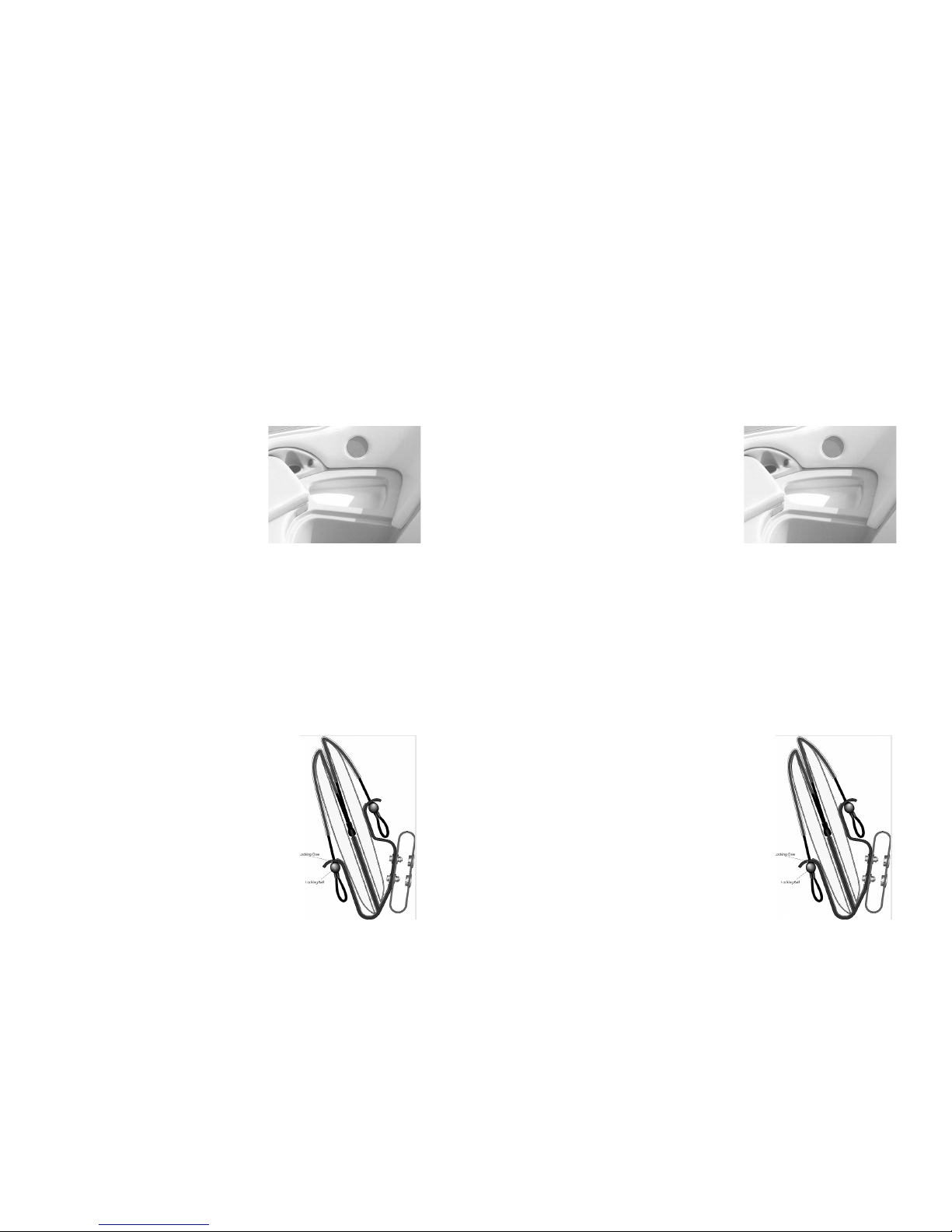
To open the engine hatch, press the stainless
steel button as shown in the photo. This
will release the latch. Lift up on the hatch.
There are two gas shocks that will help raise
the hatch. Be certain the engine is off
when you lift this hatch. To close and latch
this hatch, pull down on the hatch and allow
the hatch to close firmly. Be certain there
1.12
Drivers Seat Adjustment
Ski locker Latch & Locking
Fuel fill and vent
Engine hatch and storage
Driver’s Seat Adjustment
There is a lever under the driver’s seat
on the left side that allows the seat to
slide.
Ski Locker Latch
Push down on the raised portion of the
latch and the handle of the latch will pop
up. Lift the ski locker door with this
handle. Due to various environmental
conditions, equipment and other items
should not be left in storage
compartments for a long time. All
storage compartments that get wet or
damp should be left open to the air to
dry.
Fueling
There is a fuel fill on the port and
starboard side for added convenience.
Remove the slotted fuel fill cap to put
gas in the boat. There is a special “key”
for this cap. Use caution when fueling
your boat. Never fuel your boat
unattended. Use care to avoid being
splashed by fuel, or spilling fuel.
Engine Hatch and Storage
To open the engine hatch, press the stainless
steel button as shown in the photo. This
will release the latch. Lift up on the hatch.
There are two gas shocks that will help raise
the hatch. Be certain the engine is off
when you lift this hatch. To close and latch
this hatch, pull down on the hatch and allow
the hatch to close firmly. Be certain there
1.12
Drivers Seat Adjustment
Ski locker Latch & Locking
Fuel fill and vent
Engine hatch and storage

are no fingers in the way of this hatch when
you pull it down. The port and starboard
storage hatches open and close the same way.
Manual Latch Release in Trunk
Should the hatch latch need to be released
from the inside there is a ringed pin that when
pulled from the inside will release the latch
mechanism.
Engine Cooling Water Intake Shut-Off Valve
Your boat is equipped with a shut-off valve
(sea-cock) on the engine cooling water
intake. This valve can be viewed and
manipulated by lifting all three sections of
the stern seat. There is an access port located
on the carpeted bulkhead beneath the center
section of the stern seat. The access port has
a label indicating open and closed positions.
The valve can be left in the open position all
the time unless emergency conditions require
closing the valve to stop a leak or eliminate
the possibility of leakage.
Stern Seat
The stern seat is divided into three sections.
The center section hinges up to allow access
to service the V-drive and fuel tank.
The outboard sections are hinged up to allow
access to storage on the port and starboard
side of the engine.
Love Seat
Access storage under the bow area by lifting
up on the bottom of the love seat cushion.
The entire love seat will hinge upward to
allow access. You can leave this seat in the
“up” position to help dry the carpet .
Love Seat Extension
This optional seat can be placed between the
love seat and the drivers seat or behind the
drivers seat.
1.13
Love seat and wakeboard storage
Stern seat
Engine Cooling Water Intake Shut-Off
Valve
Manual Latch Release
Walk Through Windshield Opening/Latching
There are two latches on the inside starboard edge of the walk-through
windshield. Rotate both of these latches until the door can be opened. Always
have this closed and latched when towing the boat.
Dash Cooler
The dash cooler can be used to store misc. items or drinks. There is a drain
installed in this box. Do not depend on this cooler to keep valuables or
electronics dry. We suggest keeping these
sort of items in a specialized dry bag.
Bow Cooler
The Super Sport, Super Air and Team
Edition feature a 36 quart cooler under the
starboard side bow cushion.
Fuel Tank Location
The fuel tank is located under the floor
between the stringers. Your Correct Craft
dealer should perform all fuel tank service. Remove the center section of the
stern seat and remove the molded shroud to inspect fuel tank fittings.
Boarding Platform Removal
Pull the two pins that are located in the mounting brackets and lift the platform
vertically.
Battery Location
The battery is located under the center bow cushion in the open bow.
Optional Electric Sensor in Drainplug
The optional Electronic Sensor in Drainplug
“senses” when the drainplug is installed. When the
drainplug is not installed in the drain, an alarm will
sound at the dash. The ignition system must be
“unlocked” and the ignition indicator lit for this to
function. It is the responsibility of the boat
operator to make certain the drain plug is tightened
sufficiently.
Flight Clips
One set (4) of flight clips will hold a maximum of
4 wakeboards. Do not attempt to overload Flight
Clips with more than one piece of equipment per
slot. When loading boards into flight clips always
insert boards into individual slots so that the board
1.14
Bow Cooler
Flight Clips
bottoms are facing each other. Always visually inspect bungee to insure that
the locking ball is securely in the locking claw (see illustration). WARNING!
Avoid personal injury or property damage caused by flying objects.
Remove any items from flight clips when trailering boat.
Folding Instructions for Optional Flight Control Tower
In order to fold the Flight Control Tower forward, grasp the knobs found under
the support structure on the port and starboard sides of the tower. Unscrew the
threaded bolts. Rock the tower forward. The tower will rest on the grab rails
of the bow section of the boat. In the folded position, it is also recommended
that the tower be securely strapped to the grab rails. In order to reposition the
tower in the upright position, simply reverse the steps.
Optional Launch Control System
Your boat may be equipped with a water
ballast system that enhances the wake shape
for wakeboarding. This system may be in
two configurations. The system may be two
tanks located in the stern storage
compartments or it could also include a third
tank located in the storage locker by the
driver’s seat.
To fill the ballast system, launch the boat,
open the seacocks as displayed on the label, and turn on the fill pumps with the
‘FILL’ switch located on the starboard keypad. The seacocks are located
adjacent to the v-drive unit. These valves are accessed by raising the center
stern seat. Each valve has a remote operation handle located in the carpeted
panel behind the seat. The seacock for the center ballast tank, if so equipped,
is located just behind the tank and is accessed by raising the locker door
adjacent to the driver’s seat. The tanks will fill either with the boat moving
forward or at rest. Note: It may be necessary to prime the system. This can
be done by turning the pumps on and off several times or by putting the boat
in forward motion for a short time. This procedure should only be necessary
during your initial startup for the day. When the tanks are full, gauges located
on either the instrument pod or drivers console, will read “full” and water will
come out of the vent through-hull fittings located on either side of the boat.
Turn off the pumps and close the seacocks.
To empty the tanks turn on the drain pumps with the ‘EMPTY’ switch located
on the starboard keypad. When the tanks are empty turn the pumps off. There
are no valves to open or close and the tanks can be emptied when the boat is
in motion.
Winterization of Optional Launch Control System
In order to winterize the Launch Control System, take the following steps:
1.15
Launch Control Seacocks

1. Make sure the launch control system seacocks are open. Empty the system
completely using the drain pumps.
2. On boats that do not have the storage locker tank, open the rear storage
compartments, remove the two drain hoses from their through-hull fittings,
remove the two vent hoses from their through-hull fittings, unplug the drain
pump, and remove each tank from the boat. Turn the tanks upside down and
allow all the water present to drain out the vent hoses. Be sure all the water
has drained from the pumps and hoses still in the boat.
If the boat is equipped with a storage locker tank, open the locker lid and
remove the drain plug from the back side of the tank. Allow the tank to drain
completely raising and lowering the bow of the boat to insure complete
drainage. Replace the drain plug.
3. Reinstall each tank by reversing the above procedure.
Optional Correct Craft Cruise Operating Instructions
Turn system ON (light blinks slowly, indicating system is armed)
Drive to desired speed, prese ENGAGE and the system takes control of the
throttle (Light stays on steady)
Pull back on the throttle and the system disengages. (Light blinks rapidly,
indicating RESUME function is ready)
Accelerate again and the system resumes control automatically
at the last
speed used.
RESUME key feature will recall the last speed used even if the system was
shut off, completely powered down or the DISENGAGE function was used.
To go back to the previous speed, press RESUME and drive to the desired
speed.
Press both keys and the system will DISENGAGE,but remains armed. (Light
blinks slowly) This feature may be used when the operator wishes to go to
manual driving. To return to the last speed used, press the RESUME key and
drive to the desired speed. If the speed is to be changed, drive to that speed
and press engage.
INCREASE / DECREASE key can be pressed when the system is engaged to
change speed in 25 RPM increments to fine tune the speed.
User tips:
Always return to neutral and let the engine idle for two or three seconds before
turning the engine off Regularly check the black servo knob on the control
unit to make sure it is turned snugly in a clockwise direction. To do this, turn
the engine off and lift the top half of the engine box. Please note, the servo
knob cannot be moved if the engine is on.
1.16
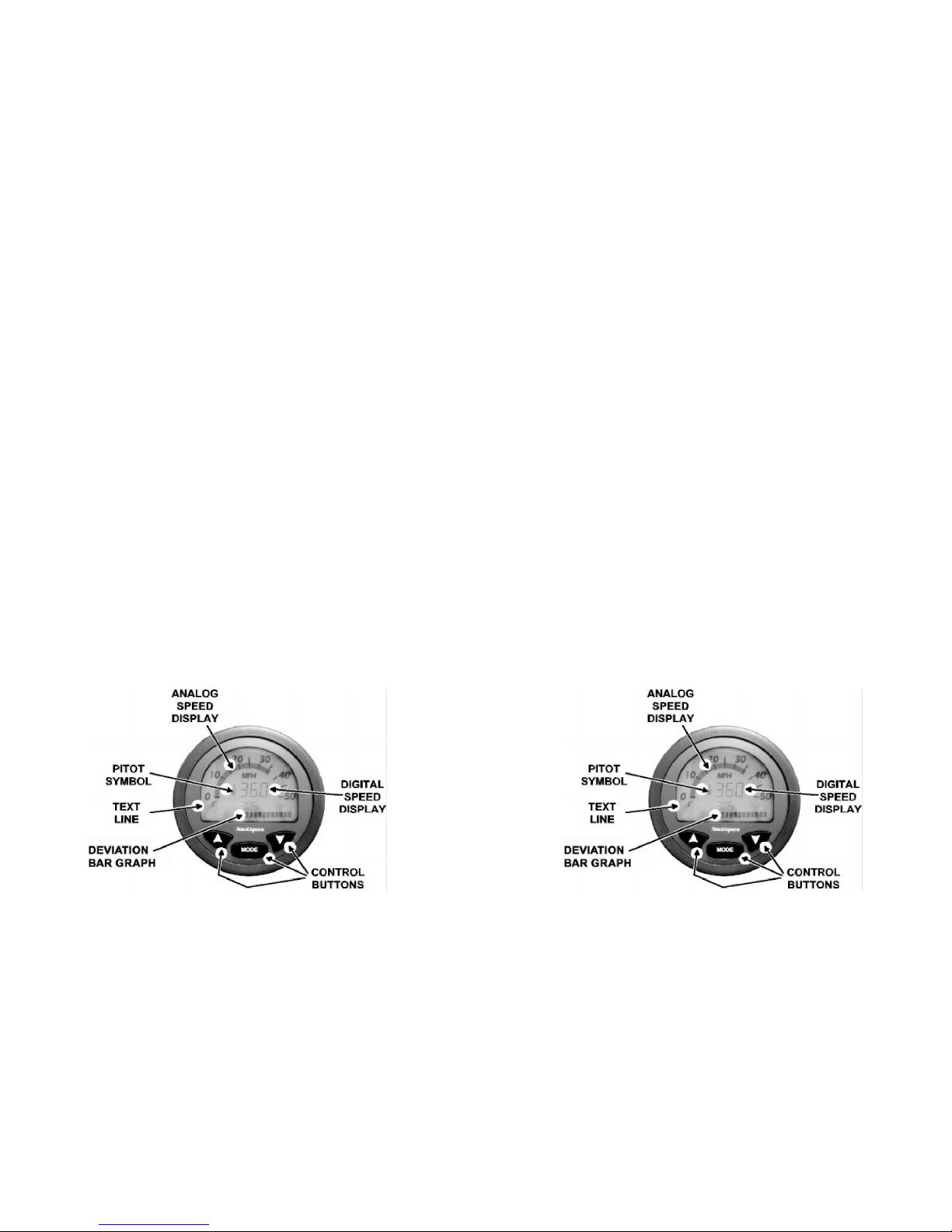
Regularly check the set screw on the side of the black knob for tightness.
The boat speed will decrease in sharp turns. If you are towing skiers, you may
wish to manually increase the throttle or use the DISENGAGE feature to
maintain speed in sharp turns.
When towing wakeboarders, accelerate slightly past desired speed prior to
engaging the speed control.
TELEFLEX LCD SPEEDOMETER AND TACHOMETER SYSTEM
The LCD Speedometer and Tachometer system consists of a speedometer
gauge, a tachometer gauge and a speed transducer assembly.
The speedometer gauge utilizes a liquid crystal display (LCD) to provide
information and three push button switches to manipulate the display. This
microprocessor-based gauge communicates with the speed transducer
assembly over a serial communication link. The speed transducer assembly
measures the pressures generated at each of the two Pitot tube pressure sources
and communicates the data to the speedometer gauge. The gauge then displays
the higher of the two sources as the current speed.
The tachometer gauge also utilizes a LCD display and push button switch
arrangement to communicate with the operator. The engine speed input to the
gauge comes directly from the engine ignition system.
Speedometer Operation
The speedometer operates in one of three “modes”. These are “Text mode”,
“Competition mode”, and “Deviation mode”. The operator may switch
between modes using the mode button.
The speedometer powers on in “Text mode” with the text line containing
“NAUTIQUES” and the deviation bar graph speed display blank. After
1.17

approximately five seconds the gauge will automatically enter “Competition
mode”.
In “Competition mode” the analog and digital speed displays will indicate
current speed and the pitot symbol will indicate which pitot tube is being used.
The deviation bar graph speed display at the bottom of the speedometer will
indicate how close the current speed is to the set point speed within the
displayed plus and minus limits. The limits can be changed from plus or minus
one mile per hour to plus or minus nine miles per hour. The current set point
speed is displayed just above the bar graph. If the current speed is below the
set point speed, bars in the deviation bar graph speed display will illuminate to
the left of center and if the current speed is above the set point speed, bars will
illuminate to the right of center. The number of bar segments that illuminate
is dependent on the deviation setting.
The set point speed can be changed while in “Competition mode” by pressing
the mode button or the up and down arrow buttons. Pressing the mode button
will immediately change the set point speed to the current boat speed. Pressing
an arrow button once will change the set point speed either up or down by one
tenth of a mile per hour. Pressing and holding an arrow button for
approximately one and a half seconds will cause the set point speed to change
by one mile per hour. Each successive arrow button push before another one
and one half seconds has elapsed will cause the set point speed to change by
one mile per hour. After the time has elapsed without a button push the
speedometer reverts to changing the set point speed by one tenth of a mile per
hour per button push.
The bar graph deviation can be changed by pressing and holding the mode
button until the speedometer changes to “Deviation mode”. The text line will
display deviation X, where X is the current deviation value. Pressing the
arrow buttons will cause the deviation to change in one mile per hour
increments. After a time out period the speedometer will automatically return
to “Competition mode”. The speedometer will go to the “Text mode” if the
mode button is pressed before the time period has expired. Once in “Text
mode” it is necessary to push the mode button again to return to “Competition
mode”.
In order to calibrate the speedometer it must be in “Competition mode”. Press
both arrow buttons simultaneously and the text line display will have a “P” on
the left, an “S” on the right, and “EXIT” in the middle. Each Pitot tube can be
calibrated separately by using one of the arrow buttons to select the desired
Pitot tube. After a Pitot tube is selected the arrow buttons should be used to
increase or decrease the constant for that Pitot tube. Increasing the constant
will increase the speed reading for that Pitot tube and vice versa. Once a Pitot
tube is calibrated press the mode button to exit back to the calibration display
and select the other Pitot tube if necessary then follow the same procedures or
press the mode button to exit.
1.18
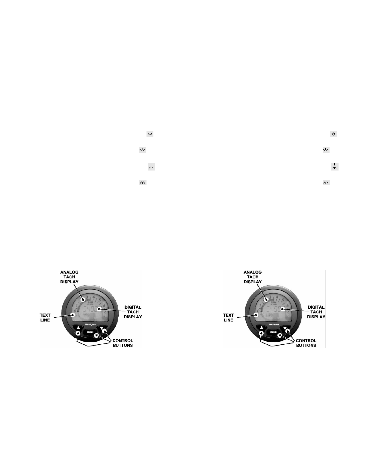
The pitot symbol indicates which Pitot tube is used to display current speed
and to indicate whether or not a Pitot tube is clogged. Below is a list of the
symbols and their meaning:
Port pitot tube used for display; Starboard pitot tube is functional:
Port pitot tube used for display; Starboard pitot tube clogged:
Starboard pitot tube used for display; Port pitot tube is functional:
Starboard pitot tube used for display; Port pitot tube clogged:
The set point, deviation and calibration values are stored in non-volatile
memory. When the speedometer is powered on, it will recall the last valid
values set.
Tachometer Operations
The tachometer displays current engine speed in revolutions per minute in both
the analog and digital tach displays. The text line displays elapsed engine
hours in one-tenth hour increments. The elapsed time will only increment if
engine speed is over 400 RPM to prevent counting time when the ignition is
on but the engine is not running. Elapsed engine hours are stored in nonvolatile memory and are recalled when the tachometer is powered on. Engine
hours cannot be set ahead or back.
1.19

1.20
1.20

Chapter 2
ENGINE O VERVIEW
It is the owners responsibility to check all of the items below to be certain
all preparation steps have been completed before you use your boat.
Checking these items periodically will soon become habitual. If leaks or other
abnormal conditions are found, stop using the boat and contact your Correct
Craft dealer to have the problem(s) corrected.
The following instructions are vitally important:
• Raise the center engine hatch all the way up. Check to see if all the engine
drain plugs are in. Make sure the hull drain plug down in the bilge and also
the drain plug at the transom are installed.
• Look at all the hoses to make sure they are installed and the hose clamps are
tight. Close the engine hatch and turn on the blower (switch is on the dash).
Run the blower at least four (4) minutes. This helps to remove fuel vapors
that might be down in the bilge before starting engine. Remember, if you
have detected the presence of fuel vapors, do not start engine until source has
been determined, any problems corrected and vapors removed.
Very Important!
• Check all gasoline line connections. These connections are located at the fuel
tank, the Fuel Control Cell and the fuel injection system. All Correct Craft
boats are equipped with anti-siphon valves on the outlet fittings of the fuel
tanks to reduce the chance of fuel siphoning from the fuel tank if a fuel hose
leaks or is severed.
• Fill the fuel tank and check for leaks. Check again for leaks after the engine
has run for a few minutes.
Check list before starting:
1) Engine oil level - boat must be sitting level.
2) Transmission oil level - boat must be sitting level.
3) Shifting linkage and detent in forward, neutral and reverse.
4) Leaks (water, fuel and oil).
5) Coolant level (if the engine is freshwater cooled).
6) Operation of the throttle and transmission shift control.
7) Battery condition.
8) Visually inspect for any loose mounting fasteners.
9) Verify the emergency engine cut off switch located by the throttle is
fully functional. Clip the safety lanyard securely to your body at all times
while you are driving.
10) V-Drive Oil Level - boat must be sitting level
2.1

2.2
• Once the boat is in the water, visually check for water leaking at the stuffing
box. This stuffing box must drip a moderate amount of water to properly
lubricate the drive shaft. If the water is rapidly coming in, pull the boat out
and have the dealer adjust the stuffing box. There is a detailed instruction for
this in the boat care section. (This stuffing box has left-hand threads)
• Check to make sure there are no ropes, gear bags, arms/legs near the belts and
pulleys of the engine. Severe injury can result by becoming entangled in the
belts of the engine while it is running. Make sure the boat is deep enough in
the water to supply the water intake with water to cool the engine. Move the
throttle into the neutral position. This is in the “straight up” position.
W
ARNING: Before you start your engine, always ventilate the engine
compartment by running the blower for four (4) minutes to remove any
fuel fumes that may be in the bilge. This is especially important after
repairing or refueling to check for fuel spills or leaks before starting the
engine.
• Close the engine hatch.
• Start the engine.
CAUTION: Do not continue to operate the starter for more than 30
seconds without pausing to allow the starter motor to cool off for five (5)
minutes. This allows the battery to recover between starting attempts.
W
ARNING: In order to prevent personal injury to you or others, whenever
the engine is running the engine hatch must be closed. Never operate the
engine with the engine hatch open or while someone is in the area of an open
engine hatch. Never open the engine hatch unless the engine is turned off
and rotating parts are stationary and remain in a stationary position.
Rotating machinery can cause injury and even death if an accident should
occur. IT IS RECOMMENDED THAT ALL WORK ON THE ENGINE BE
DONE BY TRAINED AND QUALIFIED SERVICE PERSONNEL.
During the warm up period, scan the gauges for correct operation of all
the systems:
• Oil pressure 35- 80 PSI (Approx.) at 2000 RPM
• Cooling water flow and water temperature 140-170 degrees
• Cooling water temperature for fresh water systems: 170 - 210 Degrees
• Volts should rise to around 13 - 14 volts or higher
• Idle RPM (600 - 700) in gear
CAUTION: Do not operate at high RPM’s in neutral. Do not shift into
forward or reverse at engine speeds above idle RPM’s.
CAUTION: Do not operate engine without cooling water flowing through
the water pump or the neoprene water pump impeller will become
damaged, and severe engine damage may result.

If the fuel injected engine does not start:
• If the fuel filter has just been changed or if the fuel system has been run dry,
it will be necessary to cycle the ignition start button from the “stop” position
to the “start”position several times until the fuel pumps build adequate
pressure. The cycling of the ignition is necessary because the fuel pumps will
run only 1-2 seconds when the ignition is turned on, unless the engine starts.
The throttle control should stay in neutral during engine ignition. If the
throttle is advanced, it is possible for the computer to think that the engine is
flooded and initiate a “clear flood” condition which will shut off fuel to the
engine and not allow it to start. The idle speed flare normally encountered on
hot or cold start is perfectly normal. This is programmed into the computer.
When the engine starts the idle speed will jump to approximately 1,500 rpm
and quickly decrease to somewhere between 750 and 900 rpm.
• Check for gasoline and cooling water leaks on the engine.
• Check for cooling water circulation (look at the water filter at the rear port
side of the engine for water movement).
Flooded engine
If your engine does become flooded, use caution when attempting to start the
engine. Push in the transmission disengagement button at the bottom of the
throttle arm and push the throttle to full throttle position. By pushing the button
in, the shift linkage is disengaged and the transmission remains in neutral
during the starting procedure. Run the starter until the engine starts.
To protect your investment, we suggest that you bring your boat back to your
local dealer after 25 hours of operation for an inspection of the shaft alignment,
stuffing boxes adjustment, and have the fuel system checked for leaks. This is
not a free service. Follow Pleasure Craft Marine’s (PCM) recommendations in
the maintenance section for additional service to the engine. (See Chapter 8)
Consult your dealer to determine what charges will apply.
When the engine starts, move the throttle lever back until the engine is running
about 2,500 RPM or less. Check the gauges for normal readings and let the
engine run for a minute to burn the excess fuel. If the gauge readings are
abnormal, shut the engine off immediately and contact your Correct Craft
dealer. When the engine runs normally, check the engine for fuel, water and
exhaust leaks. If there are leaks, these must be corrected before you continue.
NOTE: Read the “Notice to Dealer” sticker inside the engine hatch. These
preparation checks have probably been completed by your dealer, but it is the
owner’s responsibility to check these items. This will also help you become
more familiar with your boat.
2.3

After your initial run:
• Check oil level in the engine
• Check the transmission oil level
• Check the V-Drive oil level
• Check for leaks (water, fuel and oil)
• Engine frame bolts and mounts are tight
• Throttle and shift control operates correctly
W
ARNING: If the engine backfires when you try to start it, the problem
may be more serious than flooding. DO NOT CONTINUE TR
YING
TO START THE ENGINE; CONTACT YOUR CORRECT CRAFT
DEALER OR A QUALIFIED TECHNICIAN TO CORRECT THE
PROBLEM. To keep on trying to start the engine under these conditions
could cause engine damage or physical harm to you and those
around you.
Break In Procedure
Make sure all your passengers are properly seated before starting the break in
procedure. After the engine is thoroughly warmed up and you have driven the
boat into a large open area, open the throttle to wide open until the maximum
RPM’s are reached. Do not exceed 5,000 RPM. Reduce the throttle to 2,8003,000 RPM’s and cruise at or below this speed for 1/2 hour. Reduce the speed
to idle, open the throttle wide and operate at that speed for one minute; reduce
to the previous cruising speed for a few minutes and repeat. Accelerating from
idle speed to full throttle loads the engine and assists in seating the piston
rings. This cycle can be repeated from time to time during the first five hours
of operation, but full throttle should not be used for longer than 1-2 minutes.
W
ARNING: Follow these procedures only when conditions are such that you
can drive the boat safely..
CAUTION: Do not attempt to break in an engine by letting it idle at the
dock.
2.4

G ENERAL NOTES
The maximum RPM of the engine at full throttle under normal load conditions
can be controlled by propeller pitch, diameter and design. It is essential that the
propeller does not underload or overload the engine.
Propeller Overloading, resulting in low RPM’s at wide open throttle will
give poor performance, poor fuel economy and eventually result in engine
damage.
Propeller Underloading, if operated with a propeller that has too little pitch
or diameter, poor performance will result.
NOTE: Running your boat in shallow water can cause sand and silt to be
pulled into the cooling system. This can create excessive water pump wear and
may clog the water passages in the engine. Heavy weed growth in the water
can plug the raw water strainer and oil coolers and cause engine damage. There
is a raw water filter located near the rear of the engine that filters the water
before it goes into the transmission cooler and then the engine. Check this
every time you use the boat to make sure it is not clogged.
2.5

2.6
2.6
 Loading...