

CORRECT CRAFT Sport Nautique 216 User Manual

Dear Correct Craft Owner:
Congratulations on your purchase of a Sport Nautique 216 / Air Nautique 216.
You have chosen a boat that is unequaled “on the waters of the world” for
water-skiing and wakeboarding.
Since 1925, we have manufactured some of the finest products boat builders
can produce.
Your boat was manufactured with the latest marine technology and materials.
You have bought into a legacy handed down by W. C. Meloon over 78 years
ago. His dedication to building boats to the glory of God remains true today as
the cornerstone of our commitment in bringing to you the finest in water sports
boats. We continue to lead this industry in technology and design innovation.
Our heritage is a source of pride. Years of experience, including that of four
generations of Meloons have gone into the building of your boat. We hope that
you will enjoy it to the fullest.
Take a moment to review this owners manual for your boat. We have
assembled this manual to inform you about your boat and educate you further
on boating. There are many tips and tricks on care and maintenance sprinkled
throughout the manual, along with some cautions that will apply to your boat.
Boating is very important to us and we would like you to enjoy many years of
boating.
Welcome into the Nautique family.
Sincerely,
Walter N. Meloon
President/Chief Executive Officer
Trust in the Lord with all thine heart;
and lean not unto thine own understanding.
In all thy ways acknowledge him,
and he shall direct thy paths.
Proverbs 3:5-6
i

T ABLE OF C ONTENTS
Chapter 1. Overview ............................................... Chapter . Page
Dash Pod and Console Layout...................................1.1
Specifications..............................................................1.1
Keyless Ignition and Serial Switching.......................1.2
Multiple Keyless Ignition Codes................................1.3
Primary User Code.....................................................1.4
Erasing the User Codes ..............................................1.4
Key Functions.............................................................1.5
Dash Pod Switches.....................................................1.6
Bilge Pump.................................................................1.7
Bilge Pump Only Mode..............................................1.7
Navigation Lights ......................................................1.8
Anchor ........................................................................1.8
Ventilation Blower......................................................1.8
12 Volt Plug ...............................................................1.8
Engine Warning Light ...............................................1.8
Gauges ........................................................................1.8
Emergency Cut-off Switch ........................................1.9
Throttle .......................................................................1.9
Boarding Platform Safety............................................1.9
Pylon...........................................................................1.11
Lifting Rings ..............................................................1.12
Capacity Plate ...........................................................1.12
Hull Identification Number .......................................1.13
Driver’s Seat Adjustment ..........................................1.13
Fueling .......................................................................1.14
Ski Locker Latch.........................................................1.14
Love Seat ...................................................................1.14
Jump Seat....................................................................1.14
Walk Through Windshield..........................................1.14
Dash Cooler ...............................................................1.14
Stereo Option..............................................................1.14
Engine Box Latching/Lifting ....................................1.15
Engine Cooling Water Intake Shut-Off Valve............1.15
Stern Seat Bottom Cushion ......................................1.15
Bow Features..............................................................1.15
Trunk...........................................................................1.16
Manual Latch Release in Trunk .................................1.16
Fuel Tank Location ....................................................1.16
Optional Launch Control System...............................1.16
Winterizing Launch Control System..........................1.16
Optional Flight Control Tower (folding)...................1.17
Flight Clips.................................................................1.17
Boarding Platform Removal.......................................1.17
Battery Location..........................................................1.17
Correct Craft Cruise ...................................................1.17
Speedometer................................................................1.18
Tachometer .................................................................1.18
ii

Chapter 2. Faria Serial Bus Gauges........................2.1
Chapter 3. Engine Overview
Engine Check-List......................................................3.1
Fuel Injected Engine Does Not Start..........................3.2
Break In Procedure.....................................................3.4
General Notes..............................................................3.4
Chapter 4. Cautions and Warning Labels.................4.1
Chapter 5. Boat Handling /Safety Regulations........5.1
Chapter 6. Boat Care
Bilge Pump ................................................................6.1
Propeller ....................................................................6.2
Stuffing Box ...............................................................6.4
Quick Drain Oil..........................................................6.5
Salt Water Boating......................................................6.6
Battery Maintenance ...................................................6.6
Winterizing Your Boat................................................6.7
Gelcoat Care...............................................................6.8
Teak Care....................................................................6.9
Glass Care...................................................................6.9
Metal Care ..................................................................6.9
Vinyl Care...................................................................6.10
Tunable Rudder...........................................................6.11
Chapter 7. Trailering
Hitch ...........................................................................7.1
Security.......................................................................7.1
Towing Your Boat.......................................................7.1
Wiring.........................................................................7.1
Long Trips ..................................................................7.2
Chapter 8. Warranty and Owner Responsibility.......8.1
Chapter 9. Service Records & Order Forms
Warranty Transfer Application...................................9.1
Correct Craft Dealer/Nautique Service Center
Locations ....................................................................9.2
Nautique Friend Program...........................................9.3
NOA Membership Form ............................................9.4
Dash Plaque Order Form............................................9.6
Glossary......................................................................9.7
iii

iv
Chapter 1
O VERVIEW
Specifications Sport Nautique 216 / Air Nautique 216
Length (without platform) . . . . . . . . . 21’ 7.5”’ (6.59 m)
Length (with platform) . . . . . . . . . . . . . 23’ 5.5” (7.15 m)
Beam (measured rubrail to rubrail) . . . . . . . 91” (2,31 m)
Draft . . . . . . . . . . . . . . . . . . . . . . . . . . . . . . 24” (0.61 m)
Water line to top of Air Nautique
Flight Control Tower . . . . . . . . . . . . . . . . . . 83” (2,1 m)
Water line to top of Air Nautique
Flight Control Tower (folded forward). . . . . . . 58” (1.47 m)
Water ballast tank Capacity (Approx.. 400 lbs.) 50 Gal (189 ltr)
Approximate Weight. . . . . . . . . . . . . . . . 3280 lbs. (1,315 kg)
Lifting Rings (Distance between) . . . . . 19’ 9” (6.02 m)
Fuel Capacity . . . . . . . . . . . . . . . . . . 30 Gallons (114 ltr)
Max Capacity. . . . . . . . . . . . . . 10 people/1325 lbs. (602 kg)
Welcome to the Sport Nautique 216 / Air Nautique
216 family.
We realize you may be anxious to get your boat in
the water. This manual has been written to
familiarize and educate you about your boat so you will be more comfortable
out on the water. Your boat is built to provide you with the finest watersports
boat in the world. Whether you are slalom skiing or ripping on a wakeboard,
we trust you and your family will enjoy this boat for many years.
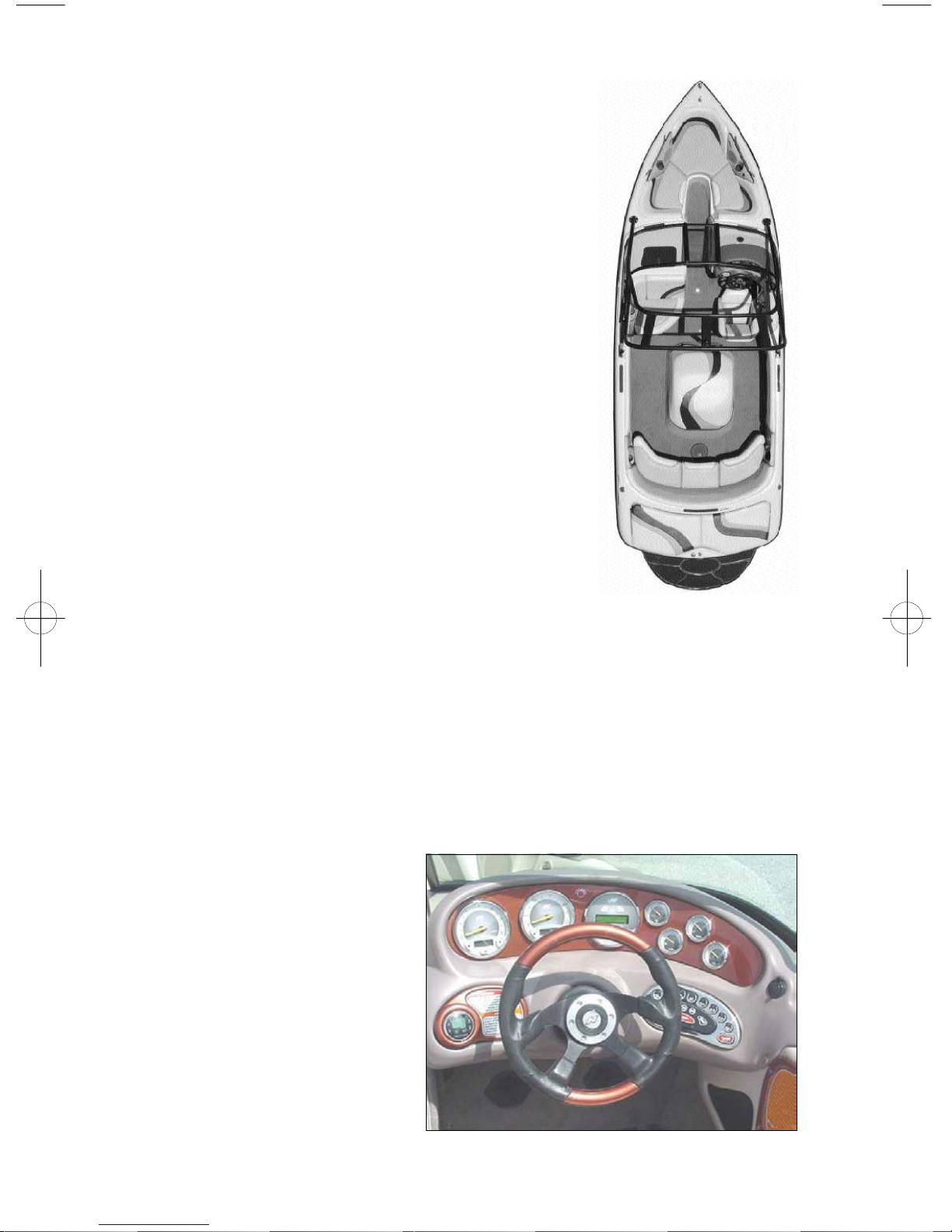
Let’s start by taking a look at the dash pod to familiarize yourself with the
locations of the gauges and switches. For 2003 Correct Craft offers three
different packages of options for your Nautique. These packages feature
equipment or gauges. Based on your purchase package, these may be
standard on your boat.
Consult your dealer for
clarification of the featured
package on your Nautique.
Dash Pod and Console Layout
Standard equipment on your
boat are the following
gauges: oil pressure, engine
coolant temperature,
speedometer, tachometer/
hour meter, fuel level,
voltage. Other equipment
based on your package may
Dash Pod
1.1
include: air/water temp gauge, clock, depthfinder,standard stereo remote
control or digital stereo remote control, Correct Craft Cruise or Perfect Pass
Digital Pro speed control. The optional gauges can be positioned on the
console located to the right of the drivers knee.
CAUTION: The keypad and switch control box will be damaged beyond repair if
the boat battery cables or the main power leads to the keypad and switch control
box are reversed. Be sure to use caution and avoid reversing these connections.
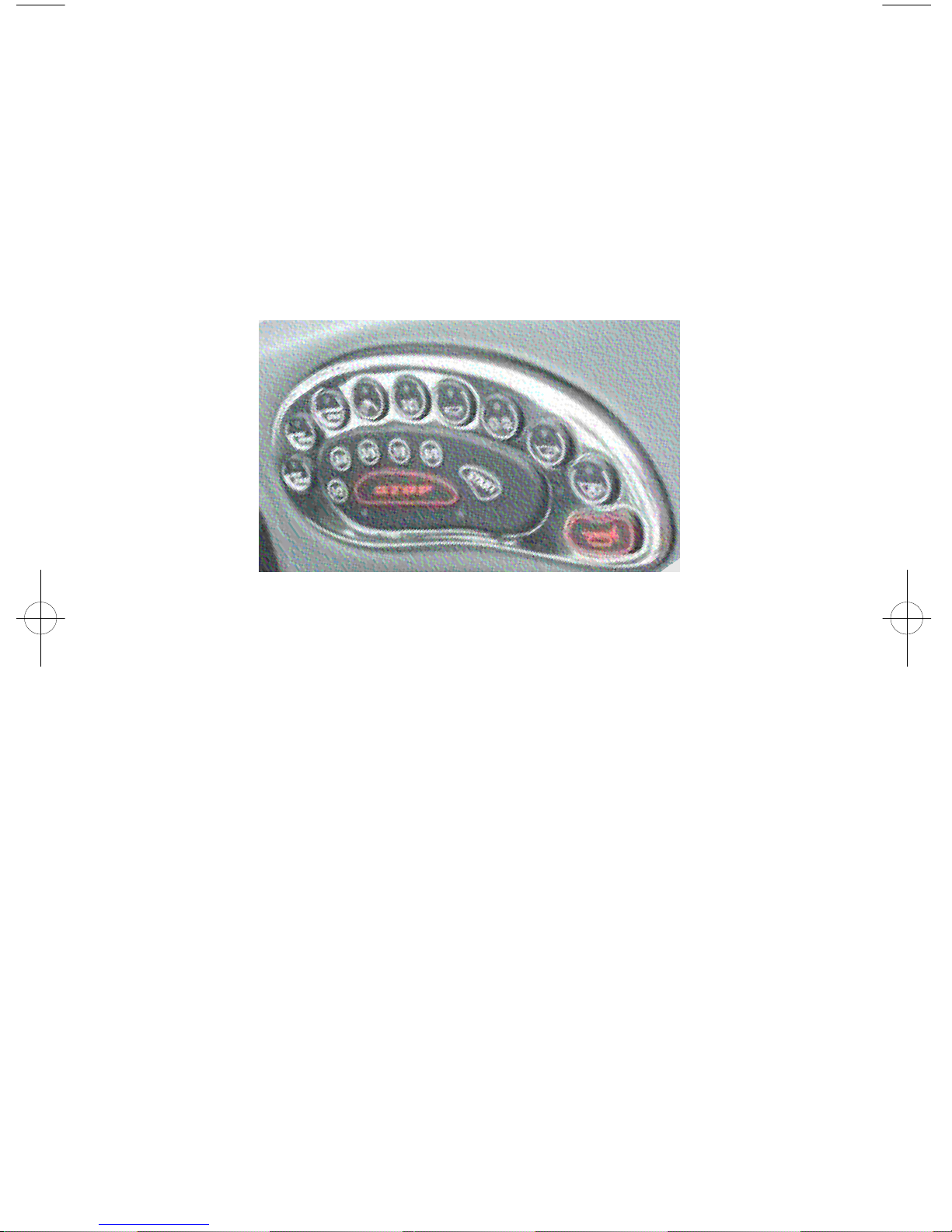
Keyless Ignition and Serial Switching
The ignition switch system is keyless and has three modes of operation.
Keyless Ignition
Locked Mode
When the boat battery is first connected, the unit is in locked mode. In this
mode, the horn, bilge pump, bilge blower, and code buttons are operational.
Unlocked Mode
Unlocked mode is entered after the user successfully enters the user code,
presses, and releases the start button. When the code keys are pressed, the
system indicator light to the right of the start button will turn on while the key
is pressed down. This indicates the button has actually been pushed. When
the system is unlocked, power is supplied to the boat and the system indicator
light will turn on. At this point all keypad buttons are operational and
actuating these buttons will control the corresponding boat functions. To put
the unit back in locked mode, the user must successfully enter the user code
then press the stop button. When the code keys are pressed, the system
indicator light to the right of the start button will turn off while the keys are
pressed down. Power will be cut to all of the accessories with the exception
of the horn, bilge pump, bilge blower and code buttons.
Run Mode
First enter the unlocked mode.
Pressing and releasing the start button quickly will put the unit in run mode.
When this is done, power is supplied to the engine ignition, but the engine will
1.2

not crank and the ignition indicator light just left of the start button is turned
on. If the start button is not pressed again within 15 minutes the unit will exit
run mode by shutting off power to the ignition and re-enter unlocked mode. If
the user presses and holds the start button, power is supplied to the ignition and
starter for as long as the user holds the start button down. All accessory
buttons are operational in this mode as well. Pressing the stop button will shut
off the engine and the unit is then put back in unlocked mode.
After the engine starts, release the start button.
Automatic Reversion to Locked Mode
If no keypad activity takes place for ten hours after unlocking, the system will
automatically revert to the locked mode. This helps to minimize battery drain.
Automatic Back-lighting
Pressing any keypad button will automatically turn the keypad back-lighting
on for ten seconds. This feature is useful for those that use their boat after dark
to find the appropriate keypad buttons.
Multiple Keyless Ignition Codes
The keyless ignition system has provision for three different ignition codes.
Any of the three codes may be used to unlock or lock the system.
The “Master Embedded Code” is programmed into the system at Correct Craft
Inc. and is not changeable, remaining with the boat for its life. This code can
be used to unlock the system, to lock the system and to erase the two user
codes.
The “Primary User Code” is programmed into the system by the owner with
the dealer’s help at the time of boat delivery. This code is used to unlock the
system, to lock the system, and to add or change the “Secondary User Code”.
The “Secondary User Code” is programmed into the system by the owner
when necessary. This code is only used to unlock or lock the system. The
“Secondary User Code” is excellent to use for limited access to the boat.
Programming and/or Changing Primary or Secondary User Code
Note: To help prevent battery drain, when you are finished using the boat
make sure you STOP the engine and LOCK the PME ignition system (two
steps). Note: The “System Indicator Light” is on the right-hand side of the
ignition keypad. The “Ignition Indicator Light” is on the left-hand side of the
ignition keypad.
Programming the Primary User Code
Make sure that the system indicator light is off. Until a primary user code is
set, the keyless ignition will behave as follows. Pressing start once will unlock
the system while pressing it a second time will start the engine. Pressing stop
1.3

once will turn off the engine while pressing it a second time will lock the
system.
To program the primary user code, press the 1/2 button and the 7/8 button at
the same time, putting the system in code programming mode. The system
indicator light will be flashing.
Enter a code from two to eight characters long and press start. For verification,
re-enter the code and press start again. The system indicator light should stop
flashing and stay on. If the light does not stop flashing, press stop and begin
again.
To lock the system re-enter either the primary user code or the master
embedded code and press stop.
Changing the Primary User Code
NOTE: The current primary code must be used to change to another primary
code.
Make sure that the system indicator light is off. Enter the primary user code
then press the 1/2 button and the 7/8 button at the same time. This puts the
system in code programming mode. The system indicator light will be
flashing.
Enter a code from two to eight characters long and press start. For verification,
re-enter the code and press start again. The system indicator light should stop
flashing and stay on. If the light does not stop flashing, press stop and begin
again.
To lock the system re-enter either the new primary user code or the master
embedded code and press stop. Please note, changing the primary code will
erase the secondary user code. The secondary code will need to be re-entered.
Programming or Changing the Secondary User Code
NOTE: The secondary code will only lock or unlock the system & can not be
used for any reprogramming
Make sure that the system indicator light is off. Enter the primary user code
and press the 1/2 button and the 5/6 button at the same time putting the system
in code programming mode. The system indicator light will be flashing.
Enter a code from two to eight characters long and press start. Re-enter the
code and press start again. The system indicator light should stop flashing and
stay on. If the light does not stop flashing, press stop and begin again.
To lock the system re-enter any of the three codes and press stop.
Erasing the User Codes
Make sure the system indicator light is off. Enter the master embedded code
and press the 1/2 button and the 7/8 button at the same time. This will erase
1.4
the system user codes.
The keyless ignition will now behave as if there are no codes in memory.
Pressing the start button will unlock the system and pressing the stop button
will lock it without entering a code. To program a primary user code, make
sure the system indicator light is off and press the 1/2 button and the 7/8 button
at the same time. This puts the system in code programming mode. The
system indicator light will be flashing. Follow the last two steps above to
complete programming the primary user code.
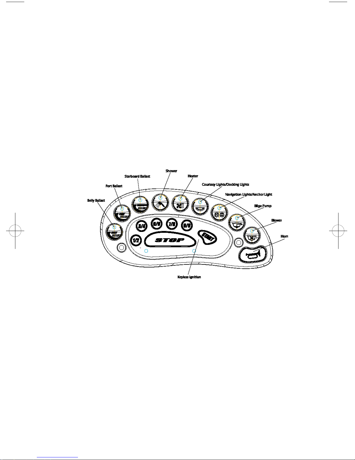
Key Functions
The following paragraphs describe the functions of individual keys on the
keypad. The keys will be described in order left to right. Each of the keys,
except for the “horn” key, has an indicator light on the top of the key. The
indicator light will be on if the function controlled by that key is on.
Function Keys
LCS or Ballast Control
The first three keys control the Launch Control System fill and drain pumps,
if the boat is equipped with a ballast tank or tanks. Various configurations can
include one single tank, two side tanks, or two side tanks and a forward
mounted tank. If the boat is equipped with a single tank the key labeled
“belly” will control the pumps for the tank. The keys for the two side tanks
are labeled “port” or “starboard” and the forward-mounted tank key is labeled
“belly.”
To turn on the fill pumps for any tank, push and quickly release the appropriate
key. This also turns on the indicator light at the top of the key. Pushing and
holding the appropriate key for a short time turns on the drain pumps and also
causes the indicator light for that key to begin flashing. Pushing and releasing
one of the keys, with either fill or drain pumps on, will turn off the pumps.
1.5

Please see the manual section covering optional LCS or ballast tanks for
complete operating instructions.
Shower
The shower is turned on or off by pressing and releasing the key. The indicator
light is on whenever the shower is on.
Heater
The heater key controls four different heater functions. Pushing and releasing
the “heater” key scrolls from “off” to “low speed” to “medium speed” to “high
speed” and back to “off.” The indicator light for this key is on if the heater is
running at anyof the three speeds.
Courtesy / Docking Lights
A quick push and release of this key turns on the indicator light and the
courtesy lights, while a push and slight hold turns on the indicator light and the
docking lights. Both the courtesy and docking lights can be turned on at the
same time, but only if the courtesy lights are turned on first. If either or both
of the two light functions are on, please note that the indicator light turns on
and a push and release will turn off any of the lights that are on.
Navigation / Anchor Light
A quick push and release of this key turn on the navigation lights and the
indicator light, while a push and slight hold will only turn on the anchor light
and will also cause the indicator light to flash. A push and release of the key
turns off either of the lights.
Bilge Pump
The bilge pump(s) is turned on or off by pressing and releasing the key. The
indicator light is on whenever the pump(s) is on.
Bilge Blower
The bilge blower is turned on or off by pressing and releasing the key. The
indicator light is on whenever the blower is on.
Horn
The horn key is strictly a momentary switch. The horn will blow whenever the
key is pushed and will stop when the key is released.
Dash Pod Switches
All dash pod switches interface with a sealed circuit breaker box located under
the bow. The circuit breaker box consists of sixteen soft opaque flexible vinyl
tubular shields which cover sixteen circuit switches. When the circuits are
functioning, the tubular shield is somewhat flexible. A tripped circuit breaker
will extend and fill the tubular shield, causing it to be inflexible. To locate a
1.61.6
tripped circuit breaker, run your fingers over the two rows of switches and
locate the switch shield that has become inflexible. To re-set, simply press in
the extended circuit switch shield.
Bilge pumps
The bilge pump switch turns on the bilge pumps.
There is a bilge pump down by the pylon and
another bilge pump back by the rudder. When
you push the bilge pump key on the keypad, both
pumps will come on and run for several moments
to “sense” if there is water in the bilge. If there
is water in the bilge, they will remain on until the
water is pumped out. If there is no water in the
bilge, they will turn off. If you want immediate
Bilge Pump
pump action, turn the switch off and then back on
again. The pumps will turn on periodically to determine if there is water in the
bilge. If so, they will remain on until the water is pumped out. Trash in bilge
can hurt bilge pump and fill pumps for ballast systems.
Note: The “Bilge” switch must be turned on for this feature to operate.
This will not drain significant power from the battery unless the bilge
pumps are required to run frequently because of a leak or excessive
rainwater. This pumping system should not be relied on over an extended
period of time. We suggest you frequently inspect your boat.
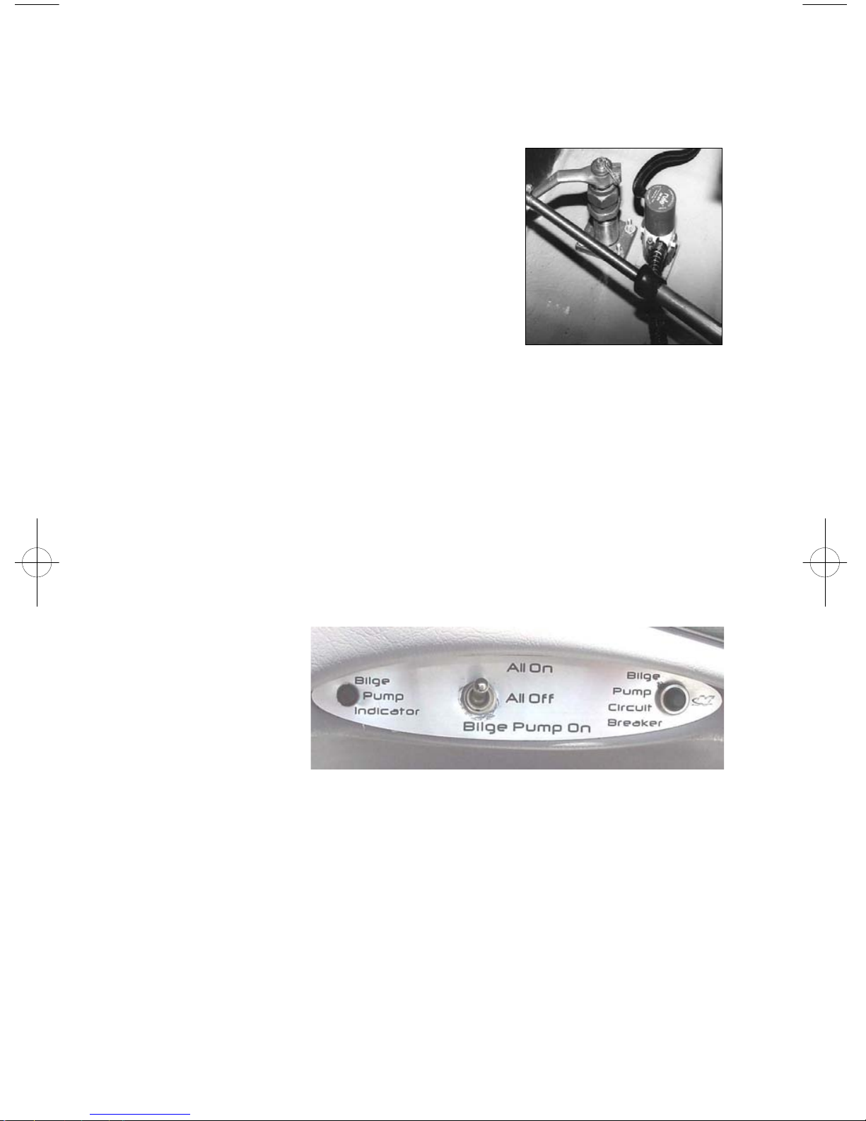
Bilge Pump Only Mode
This feature is
activated by a
switch located
below the gauges
on the side
console. The
switch has three
positions, on, off
PME Bypass
and bilge. If the boat is going to sit for more than a few days with the bilge
pump on, it is important that the switch is set in the “bilge” position to
minimize battery drain. This will activate the bilge pump and shut off power
to the Serial Switching and Keyless Ignition System. It is important to
remember that the engine or other accessories can not be used unless the
switch is in the “on” position.
Located with the switch is a circuit breaker and indicator light for the bilge
pump. The circuit breaker is only active when the switch is in the “bilge”
position. The indicator light will come on anytime the bilge pump is activated.
1.7

Navigation Lights
This switch controls the navigation lights. The law requires the bow light and
the 360 degree light (located at the transom) be turned on while running the
boat after sunset or before dawn.
Anchor
This switch turns on the 360 degree light. Insert this light pole into the
receptacle located on the transom and push the anchor switch on the pod to turn
this light on. This light is required by law to be on after sunset and before
dawn when the boat is not moving.
Accessories
There is an accessory button provided that controls power to a yellow wire
coiled up near the control box. Power to this wire is protected by a 10-amp
circuit breaker. Attaching an accessory to this wire should be done by
someone knowledgeable in DC electrical wiring.
Ventilation Blower
This switch turns on the blower in the bilge. This blower must be turned on
for four (4) minutes prior to engine ignition and also at anytime when the boat
is operated at slow speeds.
12 Volt Plug
This plug can be utilized to power cellular phones, video cameras or various
other electronics. This plug is powered through a ten (10) amp breaker.
Engine Warning Light
This light is in the center of the dash pod between the speedometer and the
tachometer and indicates high engine temperature.
Horn This is a momentary switch.
Gauges on the Pod
• Volt This gauge tells you how many volts the alternator is producing. During
normal running, it should read 13-14 volts. Running a heater, shower or
stereo amplifier will draw power from the alternator and possibly drop
voltage below normal. If this occurs, the battery will not charge correctly.
• Temp This tells you the temperature of the coolant in the engine.
• Oil Pressure This gauge tells you the engine oil pressure.
• Tachometer / Hour Meter This gauge indicates the revolutions per minute the
engine is turning, and the total accumulated engine hours.
• Speedometer Your Nautique is equipped with a speedometer by Faria. For a
detailed analysis of your speedometer, refer to the Faria speedometer section
1.8
at the end of this chapter or in Chapter 2.
• Emergency Cut-off Switch There is an emergency cut-off switch for the
protection of you and your passengers. The clip at the end of the cord must
be attached securely to the driver. Check the system by attaching the clip to
the switch, start the boat and then pull the clip off the switch. The engine
should stop. UNDER NO CIRCUMSTANCES SHOULD YOU OPERATE
THE BOAT IF THIS SYSTEM DOES NOT FUNCTION PROPERLY. If it
does not function correctly, contact your Correct Craft dealer to have the
problem corrected.
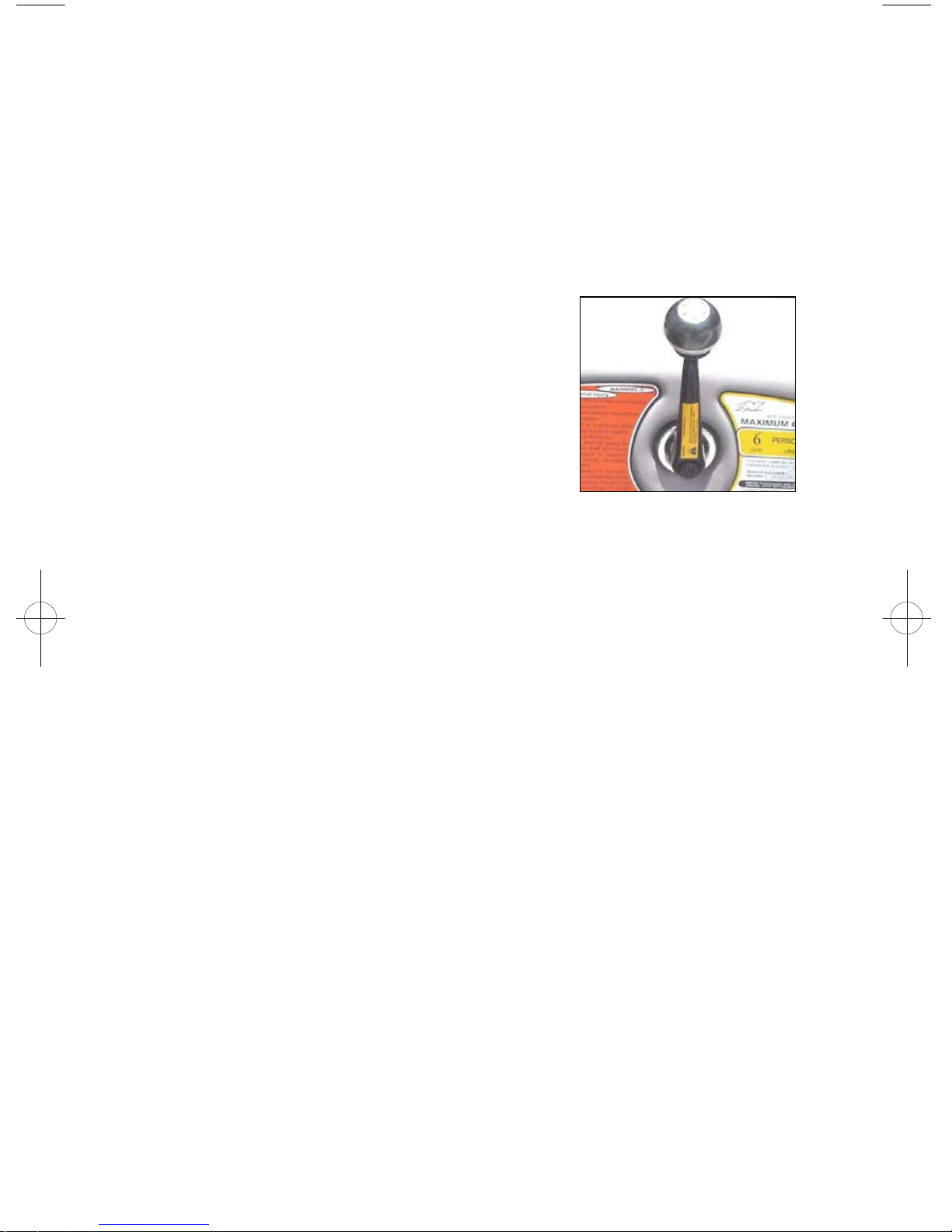
• Throttle The throttle control consists of the
throttle lever, a lock out ring and a neutral
button. The neutral button is a push-button at
the bottom of the throttle lever which allows the
throttle to be advanced without the transmission
being engaged. The throttle lever must be in the
neutral position to start the engine.
The throttle arm has three detent positions.
Throttle
Note: When in a detent position the throttle arm
will resist movement, but can be moved with sufficient pressure. Neutral
detent is straight up. Forward detent is approximately 30 degrees toward the
bow, and reverse detent is approximately 30 degrees toward the stern. Moving
the throttle from neutral detent to either forward or reverse detent will shift the
boat into that gear. The engine will remain at idle speed. To increase (forward
or reverse) engine speed and therefore boat speed, continue to rotate the
throttle arm past the detent.
Note: When shifting out of neutral, it is best to pause in the appropriate detent
before applying additional throttle.
The lockout ring mechanism prevents unintentional shifting into forward or
reverse. To operate the throttle lever, you must lift the lockout ring. DO NOT
shift quickly from forward into reverse. Stay in the neutral position until
the boat has lost speed before shifting into reverse. Shifting should not be
attempted above 1200 RPM except in emergency situations.
CAUTION: LOADING AND UNLOADING OF PASSENGERS FROM
A DOCK OR FROM THE WATER SHOULD ONLY BE DONE AFTER
THE ENGINE HAS BEEN TURNED OFF.
Boarding Platform Safety
The boarding platform of your boat is a very convenient feature that greatly
enhances the water towed sports experience. There are however, some serious
safety concerns regarding the use of the platform. Correct Craft, Inc. has
placed warning labels at the driver’s position, on the deck at the rear of the
occupant area, and on the transom.
1.9
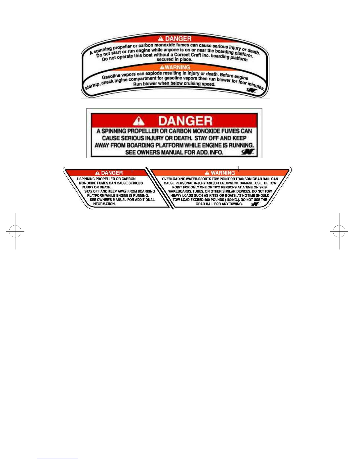
It is very important to read and be familiar with the information contained in
these labels and to always adhere to the boat operation practices described on
them. The United States Coast Guard issued a SAFETY ALERT on August
28, 2001 that cover some of the issues of improper use of the boarding
platform. The SAFETY ALERT and portions of the accompanying
information follow:
SAFETY ALERT:
The United States Coast Guard advised boaters not to “Teak/Drag Surf.”
Recent boating fatalities revealed that carbon monoxide (CO) emitted from a
vessel’s exhaust resulted in CO poisoning and the death of at least six teak
surfers. “Teak/Drag Surfing” places the individual in position directly
exposed to the CO in the engine’s exhaust. This may result in a loss of
coherent responses and even death. In addition, “Teak/Drag Surfing”
dangerously exposes the individual to a possible propeller injury, and since it
is done without a life jacket (PFD), it significantly increases the probability of
drowning. Therefore, the Coast Guard stresses, “Teak/Drag Surfing” is a very
dangerous activity and advises boaters not to participate in it.
The Coast Guard pointed out that carbon monoxide is one of the most
dangerous gases. It strikes before you know you are exposed and it impairs in
a way that can and too often doeslead to death. That is why it is so important
to the Coast Guard that in every circumstance where it can be avoided, it is.
1.10

“Why is it dangerous? It is like playing with a loaded gun,” Evans said. He
then noted, “As I explained in the previous advisory, “Teak/Drag Surfing”
entails individuals taking hold of the swim platform of a vessel while it is
underway. After a large wake builds up, they let go of the platform and body
surf. This puts the individual directly in the path of the vessel’s exhaust where
they breathe in dangerous levels of carbon monoxide. If that in itself is not
dangerous enough, the individuals are also in a position that a slight
miscalculation may throw them in to a spinning propeller. “And, it doesn’t
stop there, Evans said, in order to “Teak/Drag Surf” you cannot wear a life
jacket, the two do not go together. So, all this is a receipe for tragedy. A
tragedy that the Coast Guard wants to see averted, and that is why we are reissuing this alert.”
Pylon
The ski pylon is manufactured from high strength aluminum alloy that is
engineered for durability. It is hard coat anodized and impregnated with a
PTFE (teflon) material. If the pylon becomes loose, stop using the pylon and
take the boat to your Correct Craft dealer for service.
PYLON--WARNING/CAUTION--AVOID PERSONAL INJURY. THIS WATER
SKI PYLON WAS DESIGNED FOR WATER SKIING ONLY. ANY OTHER
USES, SUCH AS PARASAILING, KITE FLYING, TOWING OTHER BOATS
AND/OR USING AN EXTENDED PYLON, ECT., MAY OVERSTRESS THE
PYLON POSSIBLY CAUSING PERSONAL INJURY AND/OR EQUIPMENT
DAMAGE. DO NOT SIT BEHIND (AFT) THE TOW PYLON WHEN TOWING
SKIERS.
CAUTION: ALTHOUGH THE EXTENDED PYLON AND BAREFOOT
BOOMS HAVE BECOME POPULAR ADDITIONS TO MANY TOURNAMENT
INBOARDS, CORRECT CRAFT STRONGLY OBJECTS AND OPPOSES THE
USE OF ANY PYLON EXTENSION WHETHER UP OR TO THE SIDE OF
ANY OF IT’S PRODUCTS. THE USE OF PYLON EXTENSIONS CAN ALTER
THE HANDLING CHARACTERISTICS OF THE BOAT, POSSIBLY
RESULTING IN DANGEROUS INSTABILITY, WHICH COULD THEN LEAD
TO LOSS OF CONTROL; A SITUATION WHICH COULD CAUSE SERIOUS
OR FATAL INJURY TO THE BOAT DRIVER, PASSENGER(S), PERSON(S)
BEING TOWED, AND ANYONE ELSE WHO MIGHT BE IN THE VICINITY
OF SUCH A MISHAP.
CAUTION: CORRECT CRAFT DOES NOT APPROVE OF ANY
STRUCTURAL CHANGES, ADDITIONS OR MODIFICATIONS TO OUR
PRODUCTS. ANY TIME A DEALER OR CONSUMER MAKES A
CHANGE(S) TO OUR PRODUCT, THEY DO SO AT THEIR OWN RISK AND
SOLE LIABILITY. CORRECT CRAFT, INC. WILL NOT BE HELD LIABLE
FOR UNAUTHORIZED CHANGES, WHETHER DELETIONS OR
ADDITIONS, TO THE ORIGINAL EQUIPMENT / PRODUCT
MANUFACTURED AND SOLD BY CORRECT CRAFT, INC., EVEN IF
SUCH CHANGES, ADDITIONS, ECT. ARE MADE BY AN “AUTHORIZED”
DEALER, CUSTOMER, PROMOTIONAL REPRESENTATIVE OR ANY
1.11
OTHER PERSON, KNOWN OR UNKNOWN TO CORRECT CRAFT, INC.
Lifting rings
Your boat has lifting rings at the bow and at the stern. These are designed to
lift your boat in a steady and secure manner. Be certain to use a winch that has
a lifting capacity sufficient for your boat. See boat weight specs in the front of
this manual. These weights are dry weight. You must add the weight of the
battery, fuel, and gear to the dry weight.
CAUTION: DRAIN THE BILGE AND/OR LAUNCH CONTROL
SYSTEM AND/OR AFTERMARKET WATER BLADDERS(S) TO
ELIMINATE EXCESS WATER BEFORE YOU LIFT THE BOAT.
Note: Only use a hook that will pass easily through the lifting ring without
binding. This is very important. A hook that is too large or off-center could
break the lifting ring.
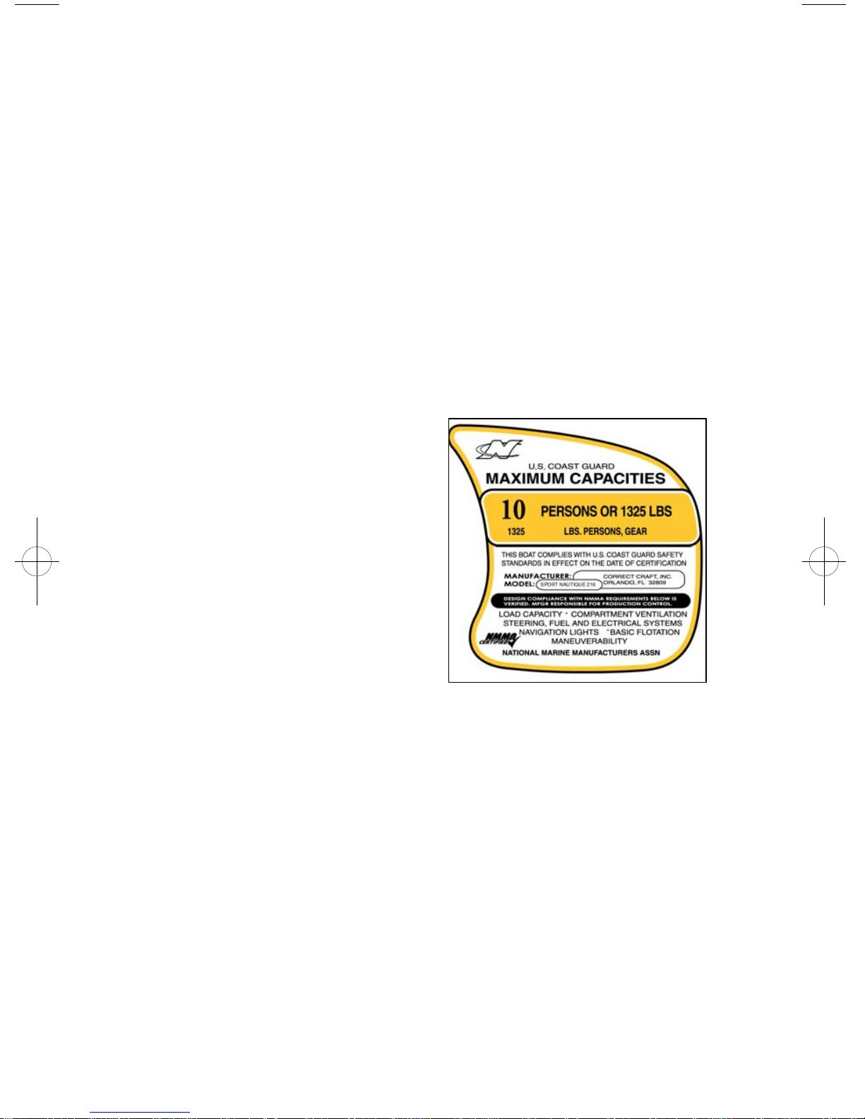
Capacity Plate
The capacity plate is used by boat
manufacturers participating in the
National Marine Manufacturers
Association certification program.
Correct Craft has submitted your model
for inspection and compliance with their
guidelines.
The capacity plate has the following
information permanently printed on it. It
is attached to the boat by the throttle for
the operator to read before they drive the
boat.
• The total weight of persons, gear and
other items which the boat is capable of
Capacity Plate
carrying under normal conditions. This
weight must include any water added to
ballast other than the Launch Control System.
• The maximum number of persons allowed on the boat.
This information on the capacity plate applies under normal conditions and
special care must be used in any other than normal conditions.
Check the capacity plate on your boat and abide by these limits.
NOTE: CORRECT CRAFT, INC. INSTALLS A PERMANENT
WAKE ENHANCEMENT BALLAST TANK SYSTEM IN SOME
MODELS. THE FULL WEIGHT OF THIS SYSTEM HAS
ALREADY BEEN CONSIDERED IN THE BOAT WEIGHT AND
THEREFORE DOES NOT INFLUENCE MAXIMUM CAPACITY,
UNLIKE PORTABLE BALLAST TANKS OR WEIGHTS, WHICH
MUST BE INCLUDED AS PART OF THE GEAR WEIGHT.
1.12
CAUTION: A FULLY LOADED NAUTIQUE WILL HANDLE
DIFFERENTLY THAN A LIGHTLY LOADED ONE. DRIVE AND
TURN YOUR NAUTIQUE WITH THIS IN MIND. AS
WAKEBOARDING HAS DEVELOPED, WE HAVE WITNESSED
THE ADVENT OF BALLAST SYSTEMS WHICH ADD WEIGHT
AND INCREASE THE SIZE OF THE WAKE. THE SIMPLEST
BALLAST SYSTEM ON THE MARKET IS THE WATER
BALLAST TYPE, SUCH AS THE ‘LAUNCH PAD”. IT IS NOT
UNCOMMON TO SEE OPERATORS USE SUCH SYSTEMS AND
THEN PUT ADDITIONAL PEOPLE IN THEIR BOAT. PLEASE BE
ADVISED THAT THIS PRACTICE CAN LEAD TO
OVERLOADING OF YOUR BOAT. EACH CORRECT CRAFT,
INC. BOAT HAS A REQUIRED CAPACITY LABEL THAT MEETS
THE MAXIMUM WEIGHT OF PEOPLE, GEAR, AND BALLAST
THAT CAN BE PLACED IN THE BOAT. ALWAYS BE AWARE OF
THE LOAD IN YOUR BOAT AND DO NOT LOAD THE BOAT IN
EXCESS OF THE LISTED CAPACITY. THE QUEST FOR THE
“PHATTEST” WAKE HAS CAUSED SOME TO EXCESSIVELY
OVERLOAD THEIR BOATS. THIS MAY ADVERSELY AFFECT
THE OPERATION OF THE BOAT, POSSIBLY RESULTING IN
INJURY TO PERSONS INSIDE AND/OR OUTSIDE OF THE BOAT.
AVOID PERSONAL INJURY. DO NOT OVERLOAD YOUR
NAUTIQUE.
Hull Identification Number
The hull identification number is a requirement of the U.S. Coast Guard for
boat manufacturers. It is a standardized numbering system that assigns a
specific sequence of numbers and letters to a specific boat. This number is
molded into the hull. You will find it on the right-hand side of the transom just
below the rubrail. Write this number down in your records and keep it in a safe
place away from the boat.
Here is a brief explanation to help you understand the hull number:
The first three digits represent Correct Craft, Inc.(CTC). The next five digits
are the boat’s serial number. The following digit is a letter from “A” through
“L” designating the month the boat was made.
There are three remaining numbers. The first of
these represent the last digit of the year the boat
was built. The final two numbers state the
MODEL year. A boat built in July of 2002 is
actually a 2003 model boat.
Driver’s Seat Adjustment
There is a lever under the driver’s seat on the left
side that allows the seat to slide.
Drivers Seat Adjustment
1.13
Fueling
There is a fuel fill on the port and starboard side for added convenience.
Remove the slotted fuel fill cap to put gas in the boat. There is a special “key”
for this cap. Use caution when fueling your boat. Never fuel your boat
unattended. Use care to avoid being splashed by fuel, or spilling fuel.
Ski Locker Latch
Push down on the raised portion of the latch and the handle of the latch will
pop up. Lift the ski locker door with this handle. Due to various environmental
conditions, equipment and other items should not be left in storage
compartments for a long time. All storage compartments that get wet or damp
should be left open to the air to dry.
Love Seat
Access storage under the bow area by lifting up on the bottom of the love seat
cushion. The entire love seat will hinge upward to allow access. You can leave
this seat in the “up” position to help dry the carpet.
Jump Seat
This optional seat can be placed between the love seat and the drivers seat or
behind the drivers seat.
Walk Through Windshield Opening/Latching
There are two latches on the inside starboard edge of the walk-through
windshield. Rotate both of these latches until the door can be opened. Always
have this closed and latched when towing the boat.
Dash Cooler
The dash cooler can be used to store misc. items or drinks. There is a drain
installed in this box. Do not depend on this cooler to keep valuables or
electronics dry. We suggest keeping these sort of items in a specialized dry
bag.
Stereo Option
All Nautiques are stereo ready. Signature models have
been pre-wired for your dealer to install a stereo. Limited
and Team Edition Nautiques come with a Clarion stereo
with Clarion speakers or a Kicker upgrade speaker
system. Correct Craft mounts all of its stereos in the glove
box on the dash of your Nautique. A standard or digital
remote control is mounted on the lower left side of the
Stereo Remote Control
dash pod. The digital remote control displays all
necessary control functions at your fingertip. Consult your dealer for the
stereo configuration in your boat.
1.14
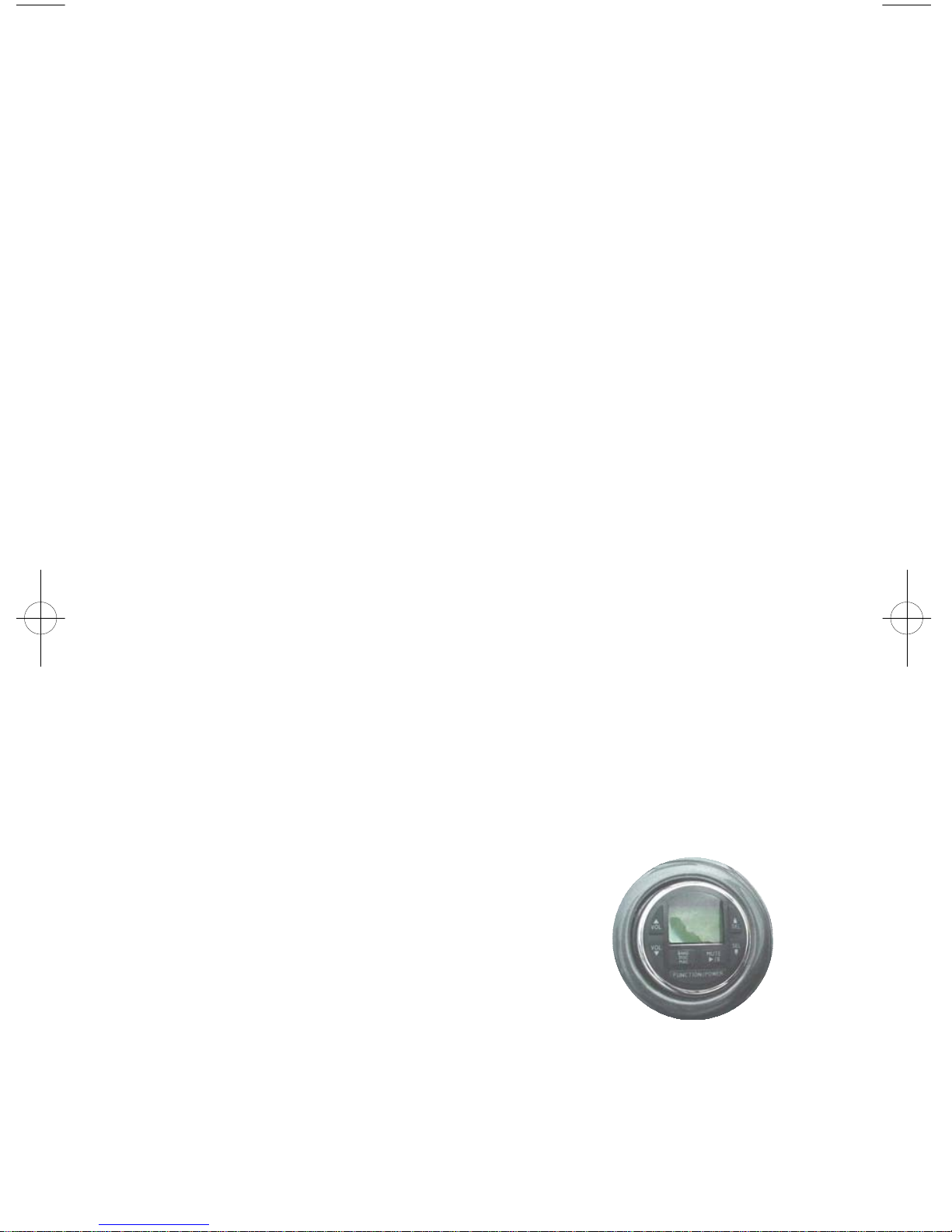
Engine Box Latching/Lifting
There are two rubber latches that hold the top of
the engine box to the base. Pull on the top of
these latches and the upper part or the engine box
will be released. Lift up on the engine box handle
and the gas shocks will help you lift the engine
box. This “clam-shell” design allows you to
check the engine without lifting the entire engine
box. You can leave the top open to dry the bilge.
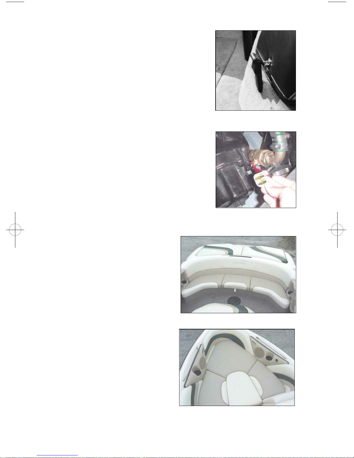
Engine Cooling Water Intake Shut-Off Valve
Your boat is equippd with a shut-off valve (seacock) on the engine cooling water intake. This
valve can be viewed and manipulated by opening
both upper and lower sections of the engine box.
The valve is located on the starboard side of the
transmission. The valve is open whenever the
handle is in line with the valve body. It is closed
when the handle is perpendicular to the valve
body. The valve can be left in the open position
all the time unless emergency conditions require
closing the valve to stop a leak or eliminate the
possibility of leakage.
Engine Box Latching
Engine Cooling Water Intake Shut-
Off Valve
Stern Seat Bottom Cushion
The stern seat bottom cushion can be
removed by releasing the port and
starboard hold down strap. The seat
cushion can then be lifted out of the
boat and stored under the bow.
Bow Features of Your Nautique
The open bow section of your boat
has removeable cushions. The
center section can be removed and
stored in the trunk or under the love
seat. The cushion on the starboard
side of the bow section can be
removed exposing an insulated
cooler. Storage on the port side and
front section is also revealed by the
removal of cushions. The speaker
mods on both the port and starboard
side house optional speakers, as well
Stern Seat Bottom Cushion
Bow Section
1.15
as a standard hot plug.
Trunk
There is 17cubic feet of storage available inside the trunk (less with the ballast
tank system). This is an excellent place to store skis, wakeboards and other
gear.
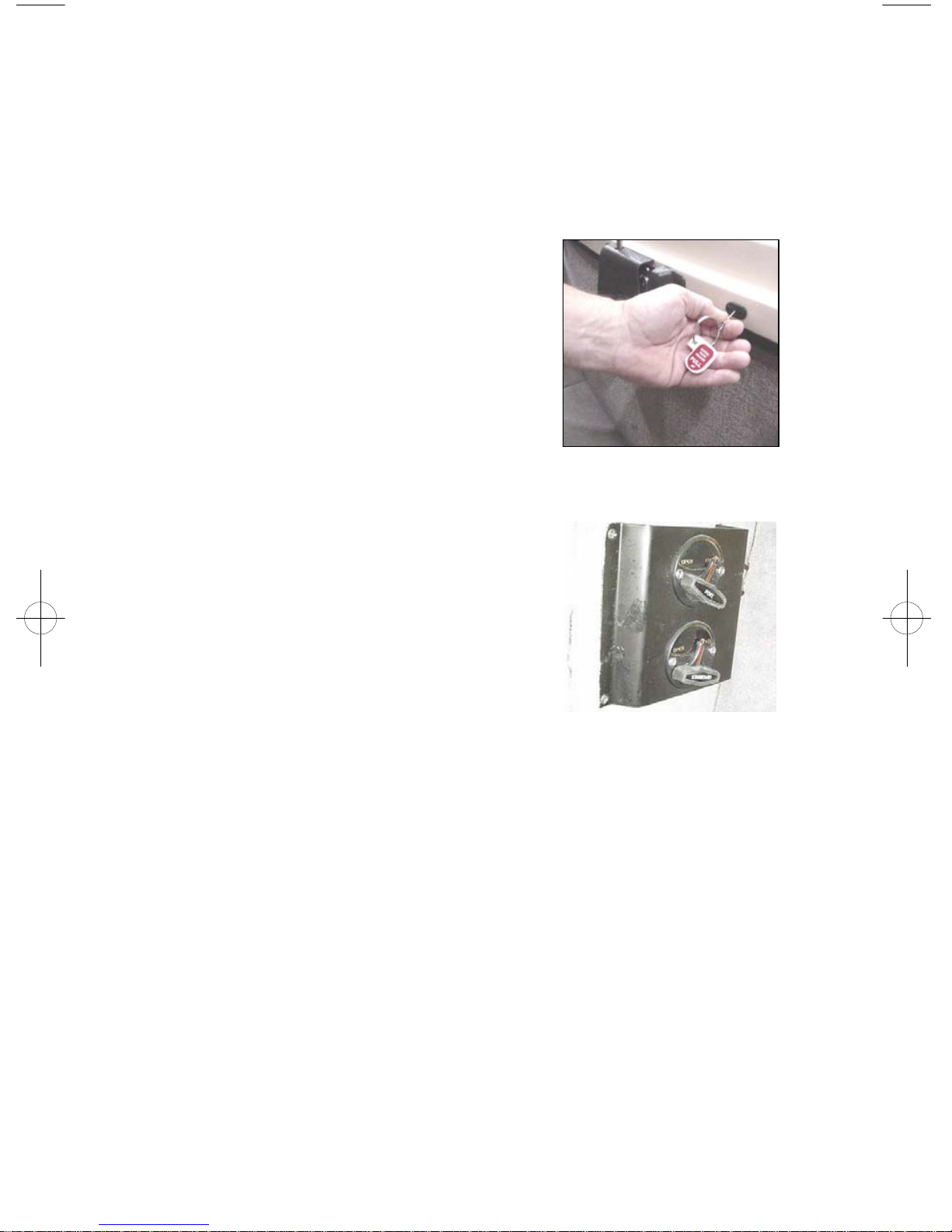
Manual Latch Release in Trunk
Should the hatch latch need to be released from
the inside there is a ringed pin that when pulled
from the inside will release the latch mechanism.
Fuel Tank Location
The fuel tank is located beneath the stern seat. To
inspect the hose connections, lift the trunk lid and
remove the curtain behind the fuel tank.
Manual Latch Release
Launch Control System (Ballast Tank Valves)
Your Nautique may come equipped with rigid
ballast tanks. Correct Craft offers a unique fill
and empty system. By opening the flow rite
valves located underneath the dash to your left
knee and then pressing the port and starboard
ballast button on the keypad on the right side of
the dash, the tanks will fill. When the tanks are
full, press the buttons again and the pump will
turn off. Then close the valves. To empty,
reverse this process by opening the valves and
Flow Rite valves
press and momentarily hold the port and starboard ballast buttons causing a
blinking light to appear. Monitor your ballast tank gauge located on the
console to determine when the tanks are empty. Then turn off pump and
close valves.
Winterization of Optional Launch Control System
In order to winterize the Launch Control System, take the following steps:
1. Make sure the launch control system seacocks (located in the bilge - see
your local dealer) are open. Empty the system completely using the drain
pumps.
2. Remove the stern seat base, engine box, and removable floor section from
the boat. Each tank has a drain hose located adjacent to the muffler on the
appropriate stringer. Remove the cap from the drain hose and allow the tank
to drain until it stops. Reach under the fuel tank and remove the empty hoses
from the empty pumps. Remove the fill hoses from the fill pumps under the
front of the engine. Raise and lower the bow of the boat while the system is
1.16
draining to insure that water is removed from the pumps.
3. Re-install all hoses, put the caps back on the drains hoses, and put the rest
of the boat together.
Folding Instructions for Optional Flight Control Tower
In order to fold the Flight Control Tower forward, grasp the knobs found under
the support structure on the port and starboard sides of the tower. Unscrew the
threaded bolts. Rock the tower forward. The tower will rest on the grab rails
of the bow section of the boat. In the folded position, it is also recommended
that the tower be securely strapped to the grab rails. In order to reposition the
tower in the upright position, simply reverse the steps.
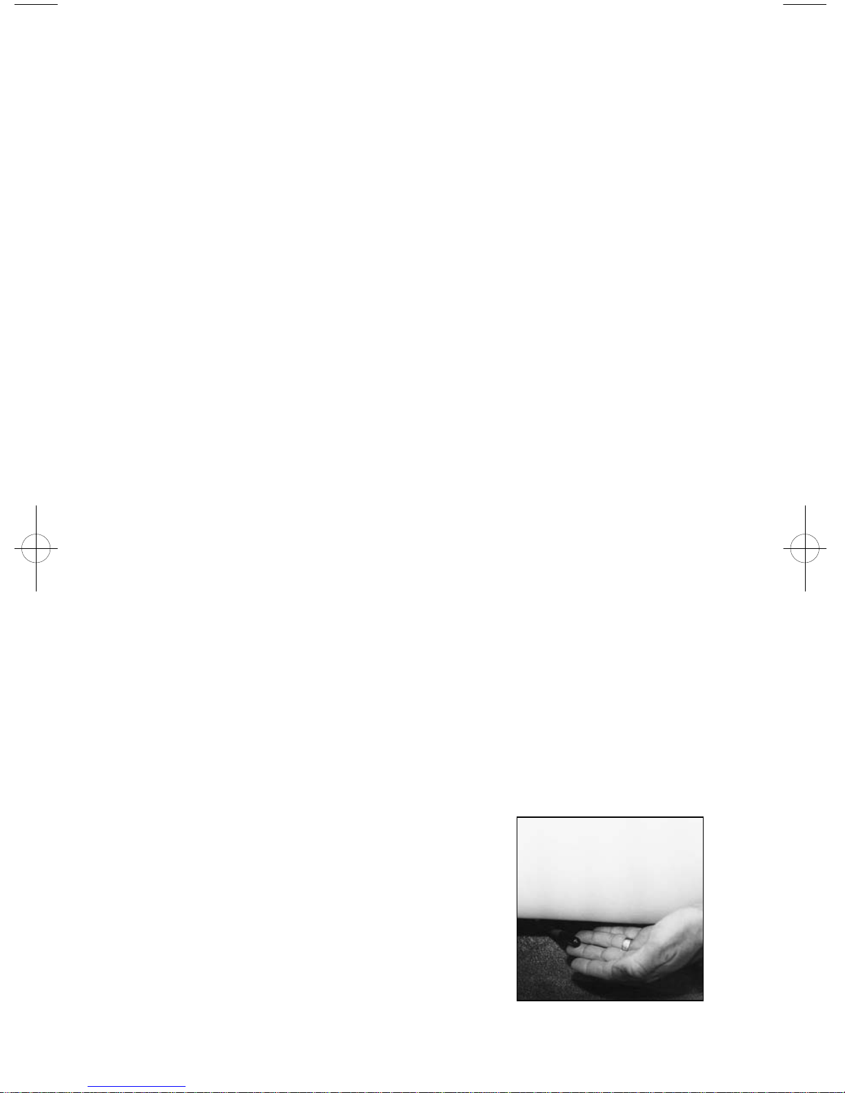
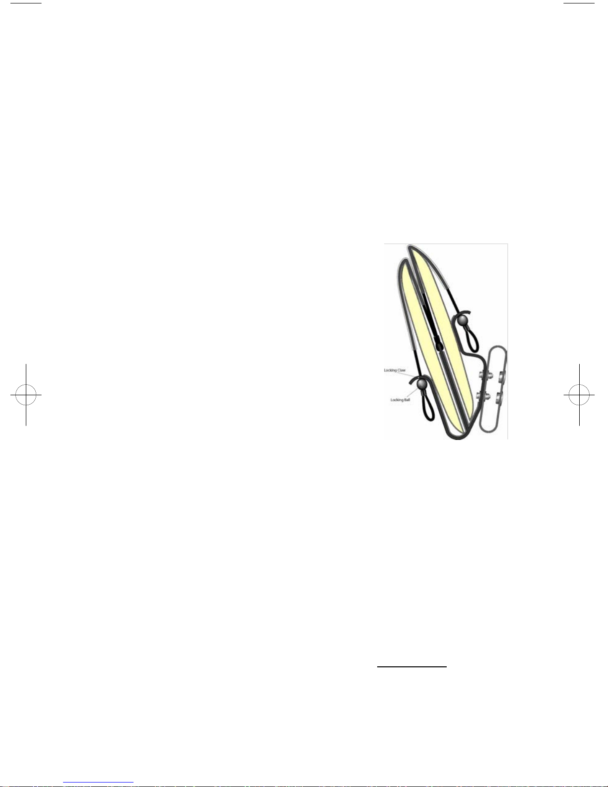
Flight Clips
One set (4) of flight clips will hold a maximum of 4
wakeboards. Do not attempt to overload Flight
Clips with more than one piece of equipment per
slot. When loading boards into flight clips always
insert boards into individual slots so that the board
bottoms are facing each other. Always visually
inspect bungee to insure that the locking ball is
securely in the locking claw (see illustration).
WARNING! Avoid personal injury or property
damage caused by flying objects. Remove any
items from flight clips when trailering boat.
Boarding Platform Removal
Flight Clips
Pull the two pins that are located in the mounting
brackets and lift the platform vertically.
Battery Location
The battery is located under the floor in front of the motor box.
Optional Correct Craft Cruise
Turn system ON (light blinks slowly, indicating system is armed)
Drive to desired speed, prese ENGAGE and the system takes control of the
throttle (Light stays on steady)
Pull back on the throttle and the system disengages. (Light blinks rapidly,
indicating RESUME function is ready)
Accelerate again and the system resumes control automatically at the last
speed used.
RESUME key feature will recall the last speed used even if the system was
shut off, completely powered down or the DISENGAGE function was used.
To go back to the previous speed, press RESUME and drive to the desired
1.17
speed.
Press both keys and the system will DISENGAGE,but remains armed. (Light
blinks slowly) This feature may be used when the operator wishes to go to
manual driving. To return to the last speed used, press the RESUME key and
drive to the desired speed. If the speed is to be changed, drive to that speed
and press engage.
INCREASE / DECREASE key can be pressed when the system is engaged to
change speed in 25 RPM increments to fine tune the speed.
User tips:
Always return to neutral and let the engine idle for two or three seconds before
turning the engine off Regularly check the black servo knob on the control
unit to make sure it is turned snugly in a clockwise direction. To do this, turn
the engine off and lift the top half of the engine box. Please note, the servo
knob cannot be moved if the engine is on.
Regularly check the set screw on the side of the black knob for tightness.
The boat speed will decrease in sharp turns. If you are towing skiers, you may
wish to manually increase the throttle or use the DISENGAGE feature to
maintain speed in sharp turns.
When towing wakeboarders, accelerate slightly past desired speed prior to
engaging the speed control.
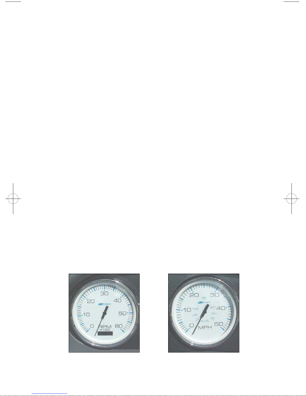
Standard Faria Instruments
All Signature Series Nautiques feature 5” Faria speedometers and tachometers.
These gauges are white faced with large tick marks for easy reading with high
contrast pointer. The gauges are paddle wheel driven with potentiometer
adjustments. Should your boat be packaged as a Limited or Team Edition,
refer to the Faria Serial Bus chapter regarding your speedometer and
tachometer.
Faria Analog Tachometer
Faria Analog Speedometer
1.18
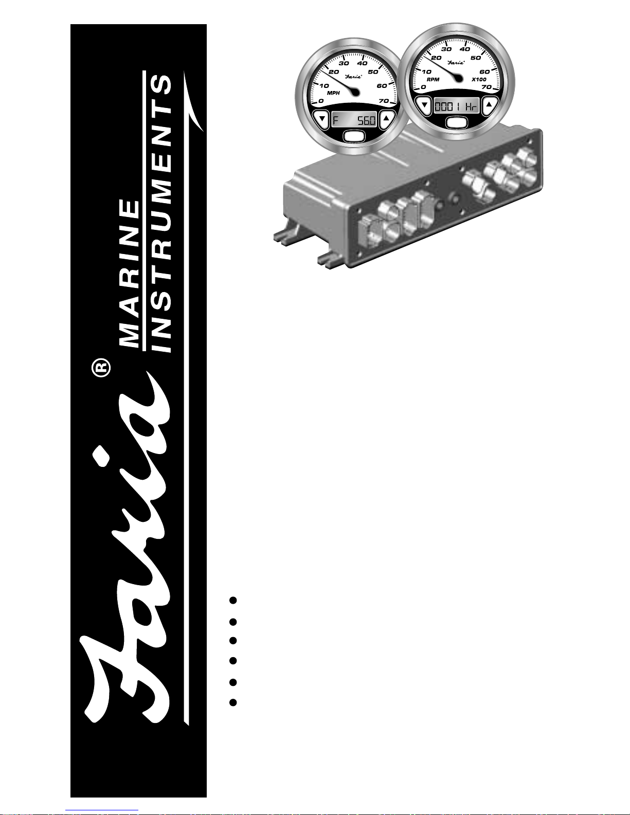
Owner’s Manual
Serial Bus
for CorrectCraft®
Pleasurecraft GM Engines
ISO151A ECR#2370 05/10/02
IS0151
Visual /Audible Alert Messages
Easy Installation
Waterproof Connections
Easy to Read Digital Displays
Easy to use Depth Sounder
Multiple Interfaces
M
M

Index
Initial Setup
Selecting the Fuel Tank Size Page 2
Operation
General Page 2
Speedometer/Depth Sounder
Speedometer Calibration Page 3
Dual Pitot Operation Page 4
Depth Sounder Page 4
Canceling Depth Alarms Page 4
Shallow Alarm Page 5
Deep Alarm Page 5
Keel Offset Page 6
Units Page 6
Speedometer Mode Display Sequence- Figure 1 Page 7
Tachometer/Fuel Monitor
General Page 8
Canceling System Alarms Page 8
Engine Hourmeter Page 8
Hours Remaining Page 9
Engine Temperature Page 9
Voltmeter Page 9
Oil Pressure Page 9
Instrument Lighting Page 9
Tachometer Mode Display Sequence - Figure 2 Page 10
LCD Alarm Condition Displays Page 10-11
Installation/Harness wiring guide for PleasureCraft GM Engines
Gateway Page 13
Gateway Harness connections
Figure 3 Typical Power Connections Page 14
Figure 4 Typical Instrument Connections Page 14
Figure 5 PleasureCraft GM Engine ECU Connection Page 15
Figure 6 Transducer and Pitot Tube Connections Page 15
Figure 7 Miscellaneous Connections Page 16
Wire Harness/Connections - Table 1 Page 17

Page 2
M
Mode
Button
Down
Button
Up
Button
Initial Setup
The setup function is normally only used
for a new installation. It is not required to
follow this procedure every time the
instruments are turned on.
The tachometer is used to initialize the
fuel tank size required for the fuel
management function. Press the “mode M”
button while the power is turned on, to
enter the “setup” mode.
The LCD will show the cur rent fuel tank
size selection. The choices are displayed
with the “Up” or “Down” buttons. After
selecting the closest tank size, press and
hold the “mode M” button for 3 seconds to
save the selected size and start normal
instrument operation.
Select from one of the following fuel tank
capacity options:
29 gallon
30 gallon (default)
35 gallon
39 gallon
50 gallon
Operation
General
The Faria® Serial Bus™ system is
designed to receive information from the
engine ECU and various individual
sensors throughout the boat. This
information is transformed into digital
data which is distributed to analog and
digital instruments via a single cable
consisting of two shielded, twisted pairs of
conductors.
Each instrument selects the data which is
applicable and displays it as if it was being
received from the sender directly. One of
the two pairs of conductors carries the data
while the other pair of conductors carry
the power for the instruments.
The tachometer and speedometer each
have three push buttons which allow the
different functions of each instrument to
be activated. Following is a description of
these functions.
M
Mode
Button
S ystem
The system consists of:
• One Gateway box to interface with
MEFI IV ECU and external senders
and sensors.
• One 5” Tachometer with Fuel
Monitor
• One 5” Speedometer with Depth
Sounder
• optional second 5” Speedometer
• Various 2” instruments, including but
not limited to
• Voltmeter
• Oil Pressure gauge
• Fuel gauge
• Engine Temperature gauge
• others as specified.
Page 3
M
Mode
Button
M
Mode
Button
M
Mode
Button
Down
Button
Up
Button
Speedometer / Depth Sounder
The Serial Bus Speedometer / Depth
Sounder provides both the functions of a
speedometer and a depth sounder. The
analog speedometer is a stepper motor
instrument which looks like a standard
analog device but which is actually a
digital instrument. On small pointer
movements you may occasionally see the
pointer moving in the one third degree
“steps” that represent the accuracy of the
instrument.
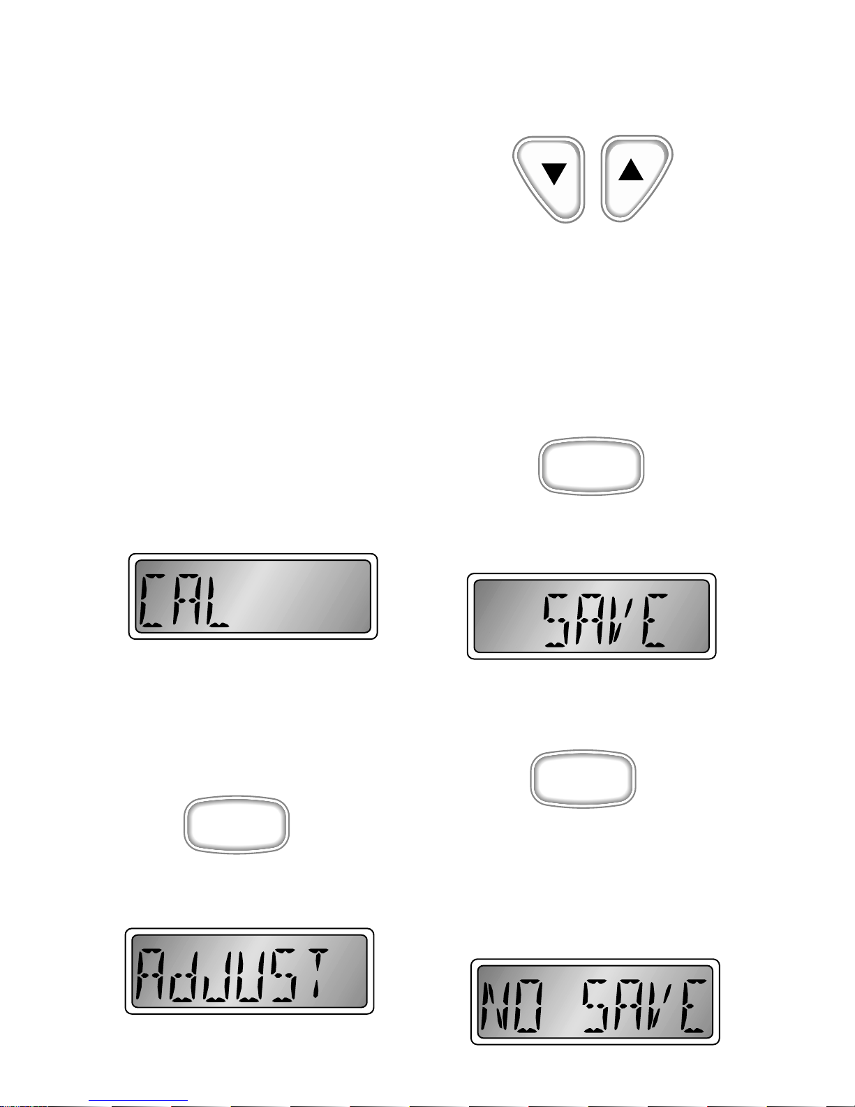
Speedometer Calibration
The analog speedometer displays the
speed of the boat through the water. The
speedometer is calibrated at the factory for
normal installations which use a pitot tube
sensor. As significant variation has been
found in various installations, the
speedometer can be easily calibrated to a
known reference such as a radar gun or
GPS. The LCD will display;
When the unit is operating in normal
mode (i.e. pitot status information on the
LCD), push a nd hold the “mode M” button
down for 2 seconds will cause the
speedometer to go to the calibration mode.
The LCD will show “AdJUST”.
Run the boat at a constant 30 MPH as
measured by the GPS or radar. Adjust the
speedometer pointer by pressing the “Up”
or “Down” buttons until the speedometer
matches the GPS or radar speed.
When finished, press the “mode M” button
to exit the adjustment screen. The operator
has the option of saving or canceling the
adjustment procedure. The options can be
selected using the “Up” or “Down”
buttons. To save the calibration setting,
press and hold the “mode M” button for 2
seconds when the display shows “SA VE”
To exit the adjustment procedure without
saving, press and hold the “mode M”
button for 2 seconds when the display
shows “NO SAVE”. Multiple runs in
opposite directions may be necessary to
compensate for errors due to water
currents.
 Loading...