

CORRECT CRAFT Sport Nautique, Air Nautique, Pro AirNautique, Super AirNautique Owner's Manual

Dear Correct Craft Owner:
Congratulations on your purchase of a Sport Nautique / Air Nautique / Pro Air
Nautique. You have chosen a boat that is unequaled “on the waters of the
world” for water-skiing and wakeboarding.
Since 1925, we have manufactured some of the finest products boat builders
can produce.
Your boat was manufactured with the latest marine technology and materials.
You have bought into a legacy handed down by W. C. Meloon over 76 years
ago. His dedication to building boats to the glory of God remains true today as
the cornerstone of our commitment in bringing to you the finest in water sports
boats. We continue to lead this industry in technology and design innovation.
Our heritage is a source of pride. Years of experience, including that of four
generations of Meloons have gone into the building of your boat. We hope that
you will enjoy it to the fullest.
Take a moment to review this owners manual for your boat. We have
assembled this manual to inform you about your boat and educate you further
on boating. There are many tips and tricks on care and maintenance sprinkled
throughout the manual, along with some cautions that will apply to your boat.
Boating is very important to us and we would like you to enjoy many years of
boating.
Welcome into the Nautique family.
Sincerely,
Walter N. Meloon
President/Chief Executive Officer
Trust in the Lord with all thine heart;
and lean not unto thine own understanding.
In all thy ways acknowledge him,
and he shall direct thy paths.
Proverbs 3:5-6
i


T ABLE OF C ONTENTS
Chapter 1. Overview ............................................... Chapter . Page
Dash Pod and Console Layout ...................................1.1
Flight Control Tower Specs........................................1.1
Keyless Ignition and Serial Switching .......................1.2
Multiple Keyless Ignition Codes................................1.3
Primary User Code................................ .....................1.3
Erasing the User Codes ..............................................1.5
Key Functions.............................................................1.5
Dash Pod Switches .....................................................1.6
Bilge Pump .................................................................1.6
Bilge Pump Only Mode..............................................1.7
Navigation Lights ......................................................1.7
Anchor ........................................................................1.7
Ventilation Blower......................................................1.8
12 Volt Plug ...............................................................1.8
Engine Warning Light ...............................................1.8
Gauges ........................................................................1.8
Emergency Cut-off Switch ........................................1.8
Throttle .......................................................................1.9
Pylon...........................................................................1.9
Lifting Rings ..............................................................1.10
Capacity Plate ...........................................................1.10
Hull Identification Number .......................................1.11
Driver’s Seat Adjustment ..........................................1.12
Love Seat ...................................................................1.12
Ski Locker Latch.........................................................1.12
Fueling .......................................................................1.12
Walk Through Windshield (optional).........................1.12
Engine Box Latching/Lifting ....................................1.13
Dash Cooler ...............................................................1.13
Stern Seat Center Cushion .......................................1.13
Fuel Tank Location ....................................................1.13
Optional Electric Sensor in Drainplug.......... .............1.13
Optional Launch Control System................. ..............1.13
Optional Launch Control Assist Pumps............. ........1.14
Winterizing Launch Control System.................. ........1.14
Correct Craft Cruise ......................................... .........1.15
Optional Flight Control Tower (folding)......... .........1.15
Battery Location..........................................................1.15
Boarding Platform Removal.......................................1.15
Speedometer................................................................1.16
Tachometer .................................................................1.19
ii

Chapter 2. Engine Overview
Engine Check-List ......................................................2.1
Fuel Injected Engine Does Not Start..........................2.3
Break In Procedure.....................................................2.4
General Notes..............................................................2.4
Chapter 3. Cautions and Warning Labels.................3.1
Chapter 4. Boat Handling /Safety Regulations........4.1
Chapter 5. Boat Care
Bilge Pump ................................................................5.1
Propeller ....................................................................5.2
Stuffing Box ...............................................................5.4
Quick Drain Oil ..........................................................5.5
Salt Water Boating......................................................5.6
Battery Maintenance...................................................5.6
Winterizing Your Boat................................................5.7
Gelcoat Care ...............................................................5.8
Teak Care....................................................................5.9
Glass Care...................................................................5.9
Metal Care ..................................................................5.9
Vinyl Care...................................................................5.10
Tunable Rudder...........................................................5.11
Chapter 6. Trailering
Hitch ...........................................................................6.1
Security.......................................................................6.1
Towing Your Boat.......................................................6.1
Wiring.........................................................................6.1
Long Trips ..................................................................6.2
Chapter 7. Warranty and Owner Responsibility.......7.1
Chapter 8. Engine Maintenance
PCM Delivery Inspection ..........................................8.1
Changing the Engine Oil ..........................................8.3
Engine Crankcase Capacity/Level .............................8.4
Raw Water Strainer ...................................................8.5
Transmission Cooler ..................................................8.5
iii

Chapter 8. Engine Maintenance...
Replacing Fuel Filter ..................................................8.5
Prolonged Storage .....................................................8.6
Exhaust System .........................................................8.6
PCM Transmissions....................................................8.6
Maintaining Transmission Fluid Level ......................8.7
Adjusting the Water Pump Belt (Ford Only) .............8.7
Alternator Drive Belt Tension....................................8.8
Fuel Pumps .................................................................8.8
Fuel Control Cell ........................................................8.8
Battery .......................................................................8.10
Fuel ............................................................................8.10
Engine Circuit Breakers on EFI Engines ...................8.11
Cooling System ........................................................8.11
Fresh Water Cooling ..................................................8.12
Checking Coolant Level ............................................8.13
Winterization Instructions......................................8.13
Winter Storage of Batteries
Recommissioning
Flushing Instruction....................................................8.18
Engine Maintenance Schedule ...................................8.19
Engine Troubleshooting..............................................8.20
....................................................8.17
...................................8.17
Chapter 9. Service Records & Order Forms
Change of Ownership.................................................9.1
Problem Notification Form ........................................9.2
Warranty Transfer.......................................................9.3
PCM Warranty ............................................................9.4
Supplemental PCM Protection Addendum ................9.5
Nautique Friend Program ...........................................9.6
Correct Craft Dealer/Warehouse Locations................9.7
NOA Membership Form ............................................9.8
Warranty Transfer Application...................................9.10
Plaque Order Form .....................................................9.11
Glossary ......................................................................9.12
iv

v

1
1

Chapter 1
O VERVIEW
Specifications Sport Nautique / Air Nautique/
Pro Air Nautique
100 % Fiberglass Construction
Length (without platform) . . . . . . . . . . 21 1.75”’ (6.4 m)
Length (with platform) . . . . . . . . . . . . 22’ 6.75” (6.88 m)
Beam (measured rubrail to rubrail) . . . . . . . 91” (2,31 m)
Draft (not under power) . . . . . . . . . . . . . . . . 24” (0.61 m)
Water line to top of Air Nautique
Flight Control Tower . . . . . . . . . . . . . . . . . . 83” (2,1 m)
Water line to top of Air Nautique
Flight Control Tower (folded forward). . . . . . . 58” (1.47 m)
Water ballast tank Capacity (Approx.. 400 lbs.) 50 Gal . (189
ltr)
Approximate Dry Weight (w/o Ballast). . 2890 lbs. (1,310 kg)
Lifting Rings (Distance between) . . . 19’ 8.5” (6.01 m)
Fuel Capacity . . . . . . . . . . . . . . . . . . 30 Gallons (113 ltr)
Note: Coast Guard Capacity (1190 lbs.) includes all added weight, including
people, fuel, ballast, FCT, etc.
Welcome to the Sport Nautique / Air Nautique / Pro Air Nautique family.
We realize you may be anxious to get your boat in the water. This manual has
been written to familiarize and educate you about your boat so you will be
more comfortable out on the water. Your boat is built to provide you with the
finest watersports boat in the world. Whether you are slalom skiing or ripping
on a wakeboard, we trust you and your family will enjoy this boat for many
years.
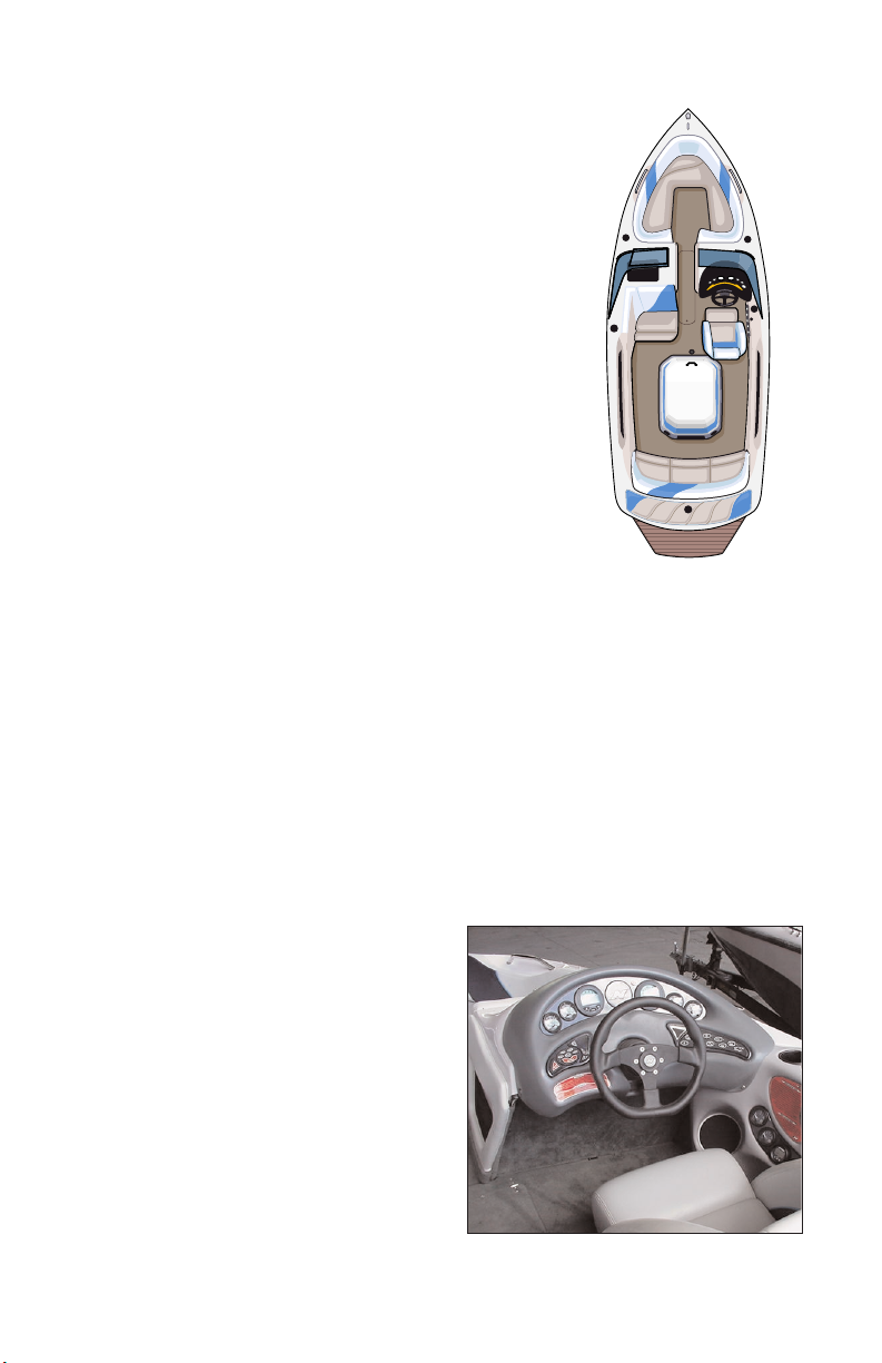
Let’s start by taking a look at the dash pod to familiarize yourself with the
locations of the gauges and switches.
Dash Pod and Console Layout
Standard equipment on your boat are
the following gauges: oil pressure,
engine coolant temperature,
speedometer, tachometer/ hour meter,
fuel level, voltage. Optional
equipment gauges available include:
air/water temp gauge, clock,
depthfinder, Launch Control System
tank gauges, remote stereo control and
Correct Craft Cruise or Perfect Pass
Pro speed control. The optional
Dash Layout
gauges are positioned on the console
1.1

located to the right of the drivers knee.
CAUTION: The keypad and switch control box will be damaged beyond repair if
the boat battery cables or the main power leads to the keypad and switch control
box are reversed. Be sure to use caution and avoid reversing these connections.
Keyless Ignition and Serial Switching
The ignition switch system is keyless and has three modes of operation.
Locked Mode
When the boat battery is first connected, the unit is in locked mode. In this
mode, the horn, bilge pump, bilge blower, and code buttons are operational.
Unlocked Mode
Unlocked mode is entered after the user successfully enters the user code,
presses, and releases the start button. When the code keys are pressed, the
system indicator light to the right of the start button will turn on while the key
is pressed down. This indicates the button has actually been pushed. When
the system is unlocked, power is supplied to the boat and the system indicator
light will turn on. At this point all keypad buttons are operational and
actuating these buttons will control the corresponding boat functions. To put
the unit back in locked mode, the user must successfully enter the user code
then press the stop button. When the code keys are pressed, the system
indicator light to the right of the start button will turn off while the keys are
pressed down. Power will be cut to all of the accessories with the exception
of the horn, bilge pump, bilge blower and code buttons.
1.2

Run Mode
First enter the unlocked mode.
Pressing and releasing the start button quickly will put the unit in run mode.
When this is done, power is supplied to the engine ignition,but the engine will
not crank and the ignition indicator light just left of the start button is turned
on. If the start button is not pressed again within 15 minutes the unit will exit
run mode by shutting off power to the ignition and re-enter unlocked mode. If
the user presses and holds the start button, power is supplied to the ignition and
starter for as long as the user holds the start button down. All accessory
buttons are operational in this mode as well. Pressing the stop button will shut
off the engine and the unit is then put back in unlocked mode.
After the engine starts, release the start button.
Automatic Reversion to Locked Mode
If no keypad activity takes place for ten hours after unlocking, the system will
automatically revert to the locked mode. This helps to minimize battery drain.
Automatic Back-lighting
Pressing any keypad button will automatically turn the keypad back-lighting
on for ten seconds. This feature is useful for those that use their boat after dark
to find the appropriate keypad buttons.
Multiple Keyless Ignition Codes
The keyless ignition system has provision for three different ignition codes.
Any of the three codes may be used to unlock or lock the system.
The “Master Embedded Code” is programmed into the system at Correct Craft
Inc. and is not changeable, remaining with the boat for it’s life. This code can
be used to unlock the system, to lock the system and to erase the two user
codes.
The “Primary User Code” is programmed into the system by the owner with
the dealers help at the time of boat delivery. This code is used to unlock the
system, to lock the system, and to add or change the “Secondary User Code”
The “Secondary User Code” is programmed into the system by the owner
when necessary. This code is only used to unlock or lock the system. The
“Secondary User Code” is excellent to use for limited access to the boat.
Programming and/or Changing Primary or Secondary User Code
Note: To help prevent battery drain, when you are finished using the boat
make sure you STOP the engine and LOCK the PME ignition system.(two
steps) Note: The “System Indicator Light” is on the ignition keypad below
the number four (4). The “Ignition Indicator Light” is also on the keypad
below the number one (1)
1.3

Programming the Primary User Code
Make sure that the system indicator light is off and the "Master Embedded
Code" has been entered. Until a primary user code is set, the keyless ignition
will behave as follows. Pressing start once will unlock the system while
pressing it a second time will start the engine. Pressing stop once will turn off
the engine while pressing it a second time will lock the system.
To program the primary user code, press buttons one and four at the same time,
putting the system in code programming mode. The system indicator light will
be flashing.
Enter a code from two to eight characters long and press start. For verification,
re-enter the code and press start again. The system indicator light should stop
flashing and stay on. If the light does not stop flashing, press stop and begin
again.
To lock the system re-enter either the primary user code or the master
embedded code and press stop.
Changing the Primary User Code
NOTE: The current primary code must be used to change to another primary
code.
Make sure that the system indicator light is off. Enter the primary user code
then press buttons one and four at the same time. This puts the system in code
programming mode. The system indicator light will be flashing.
Enter a code from two to eight characters long and press start. For verification,
re-enter the code and press start again. The system indicator light should stop
flashing and stay on. If the light does not stop flashing, press stop and begin
again.
To lock the system re-enter either the new primary user code or the master
embedded code and press stop. Please note, changing the primary code will
erase the secondary user code. The secondary code will need to be re-entered.
Programming or Changing the Secondary User Code
NOTE: The secondary code will only lock or unlock the system & can not be
used for any reprogramming
Make sure that the system indicator light is off. Enter the primary user code
and press buttons one and three at the same time putting the system in code
programming mode. The system indicator light will be flashing.
Enter a code from two to eight characters long and press start. Re-enter the
code and press start again. The system indicator light should stop flashing and
stay on. If the light does not stop flashing, press stop and begin again.
To lock the system re-enter any of the three codes and press stop.
1.4

Erasing the User Codes
Make sure the system indicator light is off. Enter the master embedded code
and press buttons one and three at the same time. This will erase the system
user codes.
The keyless ignition will now behave as if there are no codes in memory.
Pressing the start button will unlock the system and pressing the stop button
will lock it without entering a code. To program a primary user code, make
sure the system indicator light is off and press buttons one and four at the same
time. This puts the system in code programming mode. The system indicator
light will be flashing. Follow the last two steps above to complete
programming the primary user code.
Key Functions
All keys with the exception of the bilge blower, bilge pump, horn, and the code
keys operate in unlocked or run mode. The horn, up, down, and start buttons,
(when starting the engine), are momentary buttons. All others require a press
to turn on and another press to turn off.
Exceptions
Pressing the heater button will actuate the heater in the following sequence:
Heater off (low(medium(high(back to off)
Pressing the LCS fill or drain will toggle the power to the corresponding
function. Turning either the fill or the drain on will automatically turn the
other off.
The navigation light button always controls the anchor light and if the
navigation lights are on, the anchor light button will have no affect. If the
navigation lights are off, the anchor light button will turn only the anchor light
on and off. One special feature works when the anchor lights are on. If the
user desires to turn the navigation lights on, it is unnecessary to turn the anchor
lights off. Simply pressing the navigation light button will leave the anchor
light on and turn on the bow light.
1.5
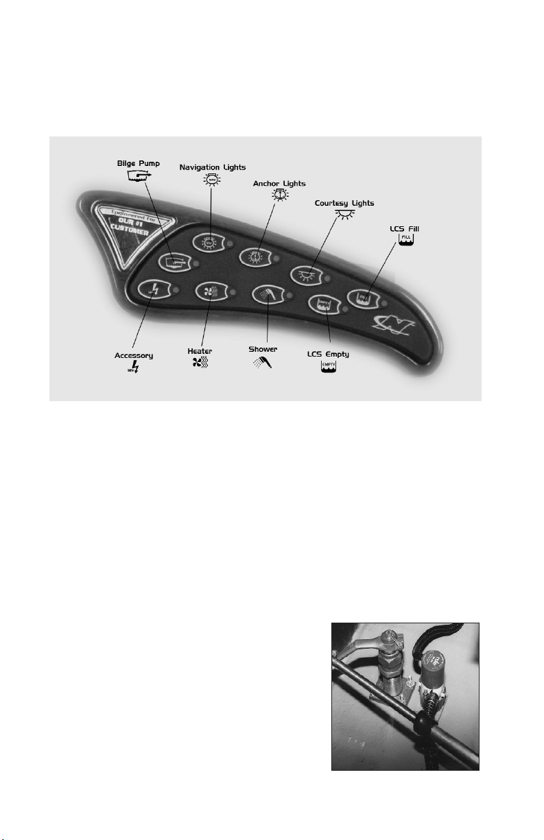
Dash Pod Switches
There are function key switches to the right of the helm and surrounding the
keyless ignition keypad. These are waterproof momentary switches. By
pressing a function key, you activate the function indicated.
All of these switches interface with a sealed circuit breaker box located under
the bow. The circuit breaker box consists of sixteen soft opaque flexible vinyl
tubular shields which cover sixteen circuit switches. When the circuits are
functioning, the tubular shield is somewhat flexible. A tripped circuit breaker
will extend and fill the tubular shield, causing it to be inflexible. To locate a
tripped circuit breaker, run your fingers over the two rows of switches and
locate the switch shield that has become inflexible. To re-set, simply press in
the extended circuit switch shield.
Bilge pumps
The bilge pump switch turns on the bilge pumps. There is a bilge pump down
by the pylon and another bilge pump back by the
rudder. When you push the bilge pump key on
the keypad, both pumps will come on and run for
several moments to “sense” of there is water in
the bilge. If there is water in the bilge, they will
remain on until the water is pumped out. If there
is no water in the bilge, they will turn off. If you
want immediate pump action, turn the switch off
and then back on again. The pumps will turn on
periodically to determine if there is water in the
bilge. If so, they will remain on until the water is
Bilge Pump
1.61.6

pumped out.
Note: The “Bilge” switch must be turned on for this feature to operate.
This will not drain significant power from the battery unless the bilge
pumps are required to run frequently because of a leak or excessive
rainwater. This pumping system should not be relied on over an extended
period of time. We suggest you frequently inspect your boat.
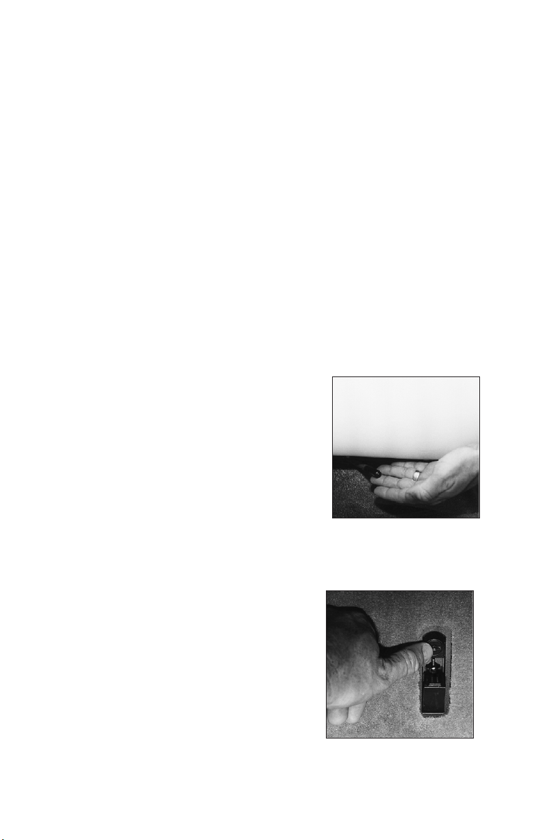
Bilge Pump Only Mode
This feature is activated by a switch located near the drivers feet on the
kickboard. The switch has three positions, on, off and bilge. If the boat is
going to sit for more than a few days with the bilge pump
on, it is important that the switch is set in the
“bilge” position to minimize battery drain.
This will activate the bilge pump and shut
off power to the Serial Switching and
Keyless Ignition System. It is
important to remember that the engine
or other accessories can not be used
unless the switch is in the “on”
position.
Located with the switch is a circuit
breaker and indicator light for the bilge
pump. The circuit breaker is only active
when the switch is in the “bilge” position. The
indicator light will come on anytime the bilge pump is activated.
Navigation Lights
This switch controls the navigation lights. The law requires the bow light and
the 360 degree light (located at the transom) be turned on while running the
boat after sunset or before dawn.
Anchor
This switch turns on the 360 degree light. Insert this light pole into the
receptacle located on the transom and push the anchor switch on the pod to
turn this light on. This light is required by law to be on after sunset and before
dawn when the boat is not moving.
Accessories
There is an accessory button provided that controls power to a yellow wire
coiled up near the control box. Power to this wire is protected by a 10-amp
circuit breaker. Attaching an accessory to this wire should be done by
someone knowledgeable in DC electrical wiring.
1.7

Ventilation Blower
This switch turns on the blower in the bilge. This blower must be turned on
for four (4) minutes prior to engine ignition and also at anytime when the boat
is operated at slow speeds.
12 Volt Plug
This plug can be utilized to power cellular phones, video cameras or various
other electronics. This plug is powered through a ten (10) amp breaker.
Engine Warning Light
This light is in the center of the dash pod between the speedometer and the
tachometer and indicates high engine temperature.
Horn This is a momentary switch.
Gauges on the Pod
• Volt
This gauge tells you how many volts the alternator is producing. During
normal running, it should read 13-14 volts. Running a heater, shower or
stereo amplifier will draw power from the alternator and possibly drop
voltage below normal. If this occurs, the battery will not charge correctly.
• Temp This tells you the temperature of the coolant in the engine.
• Oil Pressure This gauge tells you the engine oil pressure.
• Tachometer / Hour Meter This gauge indicates the revolutions per minute the
engine is turning, and the total accumulated engine hours. The tachometer /
hour meter has a digital and analog readout. Mode selection is made by
pressing the mode keypad.
• Speedometer Your Nautique is equipped with an electronic speedometer by
Teleflex. This instrument is different in many ways. It is capable of being
programmed for multiple functions. This speedometer can be calibrated. To
access the various functions, press and scroll through the Mode Key. To
change the mode, press the INCREASE or DECREASE key. For a detailed
analysis of your speedometer, refer to the Teleflex speedometer section at the
end of this chapter.
• Emergency Cut-off Switch There is an emergency cut-off switch for the
protection of you and your passengers. The clip at the end of the cord must
be attached securely to the driver. Check the system by attaching the clip to
the switch, start the boat and then pull the clip off the switch. The engine
should stop. UNDER NO CIRCUMSTANCES SHOULD YOU OPERATE
THE BOAT IF THIS SYSTEM DOES NOT FUNCTION PROPERLY. If it
does not function correctly, contact your Correct Craft dealer to have the
problem corrected.
• Throttle The throttle control consists of the throttle lever, a lock out ring and
1.8

a neutral button. The neutral button is a push-button at the bottom of the
throttle lever which allows the throttle to be advanced without the
transmission being engaged. The throttle lever must be in the neutral position
to start the engine.
The throttle arm has three detent positions.
Note: When in a detent position the throttle arm
will resist movement, but can be moved with
sufficient pressure. Neutral detent is straight up.
Forward detent is approximately 30 degrees
toward the bow, and reverse detent is
approximately 30 degrees toward the stern.
Moving the throttle from neutral detent to either
forward or reverse detent will shift the boat into
Throttle
that gear. The engine will remain at idle speed.
To increase (forward or reverse) engine speed and therefore boat speed,
continue to rotate the throttle arm past the detent.
Note: When shifting out of neutral, it is best to pause in the appropriate detent
before applying additional throttle.
The lockout ring mechanism prevents unintentional shifting into forward or
reverse. To operate the throttle lever, you must lift the lockout ring. DO NOT
shift quickly from forward into reverse. Stay in the neutral position until
the boat has lost speed before shifting into reverse. Shifting should not be
attempted above 1200 RPM except in emergency situations.
CAUTION: LOADING AND UNLOADING OF PASSENGERS FROM
A DOCK OR FROM THE WATER SHOULD ONLY BE DONE AFTER
THE ENGINE HAS BEEN TURNED OFF.
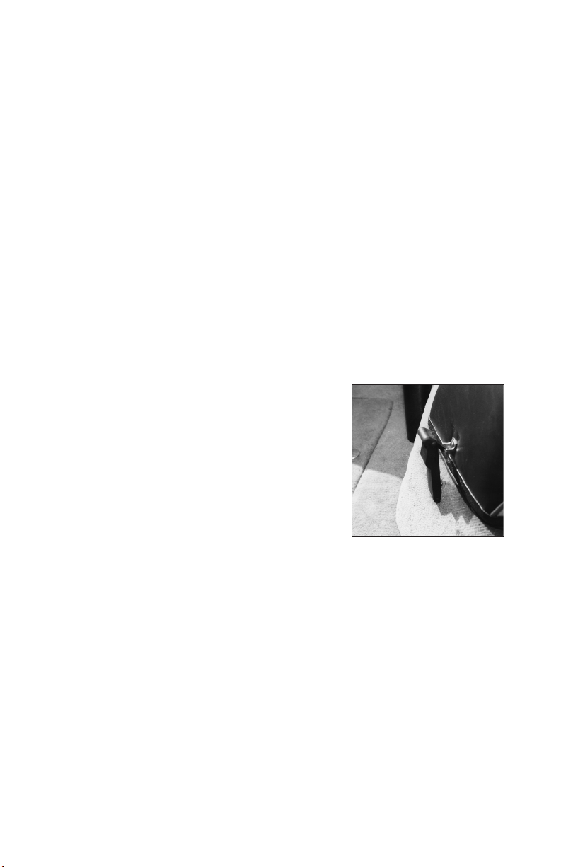
Pylon
The ski pylon is manufactured from high strength aluminum alloy that is
engineered for durability. It is hard coat anodized and impregnated with a
PTFE (teflon) material. If the pylon becomes loose, stop using the pylon and
take the boat to your Correct Craft dealer for service.
PYLON--WARNING/CAUTION--AVOID PERSONAL INJURY. THIS WATER
SKI PYLON WAS DESIGNED FOR WATER SKIING ONLY. ANY OTHER
USES, SUCH AS PARASAILING, KITE FLYING, TOWING OTHER BOATS
AND/OR USING AN EXTENDED PYLON, ECT., MAY OVERSTRESS THE
PYLON POSSIBLY CAUSING PERSONAL INJURY AND/OR EQUIPMENT
DAMAGE. DO NOT SIT BEHIND (AFT) THE TOW PYLON WHEN TOWING
SKIERS.
CAUTION: ALTHOUGH THE EXTENDED PYLON AND BAREFOOT
BOOMS HAVE BECOME POPULAR ADDITIONS TO MANY TOURNAMENT
INBOARDS, CORRECT CRAFT STRONGLY OBJECTS AND OPPOSES THE
USE OF ANY PYLON EXTENSION WHETHER UP OR TO THE SIDE OF
1.9
ANY OF IT’S PRODUCTS. THE USE OF PYLON EXTENSIONS CAN ALTER
THE HANDLING CHARACTERISTICS OF THE BOAT, POSSIBLY
RESULTING IN DANGEROUS INSTABILITY, WHICH COULD THEN LEAD
TO LOSS OF CONTROL; A SITUATION WHICH COULD CAUSE SERIOUS
OR FATAL INJURY TO THE BOAT DRIVER, PASSENGER(S), PERSON(S)
BEING TOWED, AND ANYONE ELSE WHO MIGHT BE IN THE VICINITY
OF SUCH A MISHAP.
CAUTION: CORRECT CRAFT DOES NOT APPROVE OF ANY
STRUCTURAL CHANGES, ADDITIONS OR MODIFICATIONS TO OUR
PRODUCTS. ANY TIME A DEALER OR CONSUMER MAKES A
CHANGE(S) TO OUR PRODUCT, THEY DO SO AT THEIR OWN RISK
AND SOLE LIABILITY. CORRECT CRAFT, INC. WILL NOT BE HELD
LIABLE FOR UNAUTHORIZED CHANGES, WHETHER DELETIONS OR
ADDITIONS, TO THE ORIGINAL EQUIPMENT / PRODUCT
MANUFACTURED AND SOLD BY CORRECT CRAFT, INC., EVEN IF
SUCH CHANGES, ADDITIONS, ECT. ARE MADE BY AN AUTHORIZED” ,
DEALER, CUSTOMER, PROMOTIONAL REPRESENTATIVE OR ANY
OTHER PERSON, KNOWN OR UNKNOWN TO CORRECT CRAFT, INC.
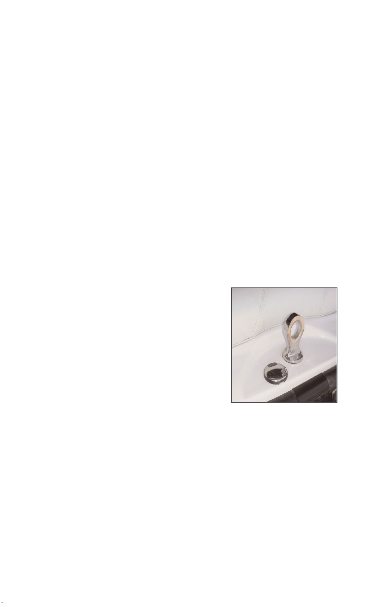
Lifting rings
Your boat has lifting rings at the bow and at the
stern. These are designed to lift your boat in a
steady and secure manner. Be certain to use a
winch that has a lifting capacity sufficient for
your boat. See boat weight specs in the front of
this manual. These weights are dry weight.
You must add the weight of the battery, fuel,
and gear to the dry weight.
CAUTION: DRAIN THE BILGE AND/OR
LAUNCH CONTROL SYSTEM AND/OR
AFTERMARKET WATER BLADDERS(S)
TO ELIMINATE EXCESS WATER
BEFORE YOU LIFT THE BOAT.
Lifting Rings
Note: Only use a hook that will pass easily through the lifting ring without
binding. This is very important. A hook that is too large or off-center could
break the lifting ring.
1.10

Capacity Plate
The capacity plate is used by boat
manufacturers participating in the
National Marine Manufacturers
Association certification program.
Correct Craft has submitted your model
for inspection and compliance with their
guidelines.
The capacity plate has the following
information permanently printed on it. It
is attached to the boat by the throttle for
the operator to read before they drive the
boat.
• The total weight of persons, gear and
other items which the boat is capable
Capacity Plate
of carrying under normal conditions. This
weight must include any water added to the Launch Control System or other
added ballast.
• The maximum number of persons allowed on the boat.
This information on the capacity plate applies under normal conditions and
special care must be used in any other than normal conditions.
Check the capacity plate on your boat and abide by these limits.
NOTE: THE USE OF ANY BALLAST SYSTEM REQUIRES THE
REDUCTION OF THE MAXIMUM LOAD CAPACITY LISTED ON
YOUR NAUTIQUE’S CAPACITY PLATE. (I.E.IF THE MAXIMUM
CAPACITY IS LISTED AS 1250 LBS AND YOU ADD 400 LBS OF
BALLAST, THEN THE TOTAL WEIGHT OF PERSONS AND
GEAR THAT YOU CAN CARRY IS REDUCED TO 850 LBS.
CAUTION: A FULLY LOADED NAUTIQUE WILL HANDLE
DIFFERENTLY THAN A LIGHTLY LOADED ONE. DRIVE AND
TURN YOUR NAUTIQUE WITH THIS IN MIND. AS
WAKEBOARDING HAS DEVELOPED, WE HAVE WITNESSED
THE ADVENT OF BALLAST SYSTEMS WHICH ADD WEIGHT
AND INCREASE THE SIZE OF THE WAKE. THE SIMPLEST
BALLAST SYSTEM ON THE MARKET IS THE WATER BALLAST
TYPE, SUCH AS THE ‘LAUNCH PAD”. IT IS NOT UNCOMMON
TO SEE OPERATORS USE SUCH SYSTEMS AND THEN PUT
ADDITIONAL PEOPLE IN THEIR BOAT. PLEASE BE ADVISED
THAT THIS PRACTICE CAN LEAD TO OVERLOADING OF
YOUR BOAT. EACH CORRECT CRAFT, INC. BOAT HAS A
REQUIRED CAPACITY LABEL THAT MEETS THE MAXIMUM
WEIGHT OF PEOPLE, GEAR, AND BALLAST THAT CAN BE
PLACED IN THE BOAT. ALWAYS BE AWARE OF THE LOAD IN
YOUR BOAT AND DO NOT LOAD THE BOAT IN EXCESS OF
THE LISTED CAPACITY. THE QUEST FOR THE
“PHATTEST”WAKE HAS CAUSED SOME TO EXCESSIVELY
OVERLOAD THEIR BOATS. THIS MAY ADVERSELY AFFECT
1.11
THE OPERATION OF THE BOAT, POSSIBLY RESULTING IN
INJURY TO PERSONS INSIDE AND/OR OUTSIDE OF THE BOAT.
AVOID PERSONAL INJURY. DO NOT OVERLOAD YOUR
NAUTIQUE.
Hull Identification Number
The hull identification number is a requirement of the U.S. Coast Guard for
boat manufacturers. It is a standardized numbering system that assigns a
specific sequence of numbers and letters to a specific boat. This number is
molded into the hull. You will find it on the right-hand side of the transom just
below the rubrail. Write this number down in your records and keep it in a safe
place away from the boat.
Here is a brief explanation to help you understand the hull number:
The first three digits represent Correct Craft, Inc.(CTC). The next five digits
are the boat’s serial number. The following digit is a letter from “A” through
“L” designating the month the boat was made.
There are three remaining numbers. The first of these represent the last digit of
the year the boat was built. The final two
numbers state the MODEL year. A boat built in
August of 2000 is actually a 2001 model boat.
Driver’s Seat Adjustment
There is a lever under the driver’s seat on the left
side that allows the seat to slide.
Fueling
Remove the slotted fuel fill cap to put gas in the
boat. There is a special “key” for this cap. Use
Drivers Seat Adjustment
caution when fueling your boat. Never fuel your
boat unattended. Use care to avoid being splashed by fuel, or spilling fuel.
Ski Locker Latch
Push down on the raised portion of the latch and
the handle of the latch will pop up. Lift the ski
locker door with this handle. Due to various
environmental conditions, equipment and other
items should not be left in storage compartments
for a long time. All storage compartments that
get wet or damp should be left open to the air to
dry.
Love Seat
Ski locker Latch & Locking
Access storage under the bow area by lifting up on the bottom of the love seat
1.12
cushion. The entire love seat will hinge upward to allow access. You can leave
this seat in the “up” position to help dry the carpet
Love Seat Extension
This optional seat can be placed between the love seat and the drivers seat or
behind the drivers seat.
Walk Through Windshield Opening/Latching
There are two latches on the inside starboard edge of the walk-through
windshield. Rotate both of these latches until the door can be opened. Always
have this closed and latched when towing the boat.
Dash Cooler
The dash cooler can be used to store misc. items or drinks. There is a drain
installed in this box. Do not depend on this cooler to keep valuables or
electronics dry. We suggest keeping these sort of items in a specialized dry
bag.
Engine Box Latching/Lifting
There are two rubber latches that hold the top of
the engine box to the base. Pull on the top of
these latches and the upper part or the engine
box will be released. Lift up on the engine box
handle and the gas shocks will help you lift the
engine box. This “clam-shell” design allows you
to check the engine without lifting the entire
engine box. You can leave the top open to dry
the bilge.
Optional Electric Sensor in Drainplug
The optional Electronic Sensor in Drainplug
Engine Box Latching
“senses” when the drainplug is installed. When
the drainplug is not installed in the drain, an alarm will sound at the dash. The
ignition system must be “unlocked” and the ignition indicator lit for this to
function. It is the responsibility of the boat operator to make certain the drain
plug is tightened sufficiently.
Stern Seat Center Cushion
The stern seat center cushion can be removed to assist getting in and out of the
boat.
Stern Seat Base Removal
The stern seat provides ample seating for three or can be removed in order to
provide additional space for equipment.
1.13
Trunk
There is 14 cubic feet of storage available inside the trunk (less with the
ballast tank system). This is an excellent place to store skis, wakeboards and
other gear.
Fuel Tank Location
The fuel tank is located beneath the stern seat. To inspect the hose connections,
lift the trunk lid and remove the curtain behind the fuel tank.
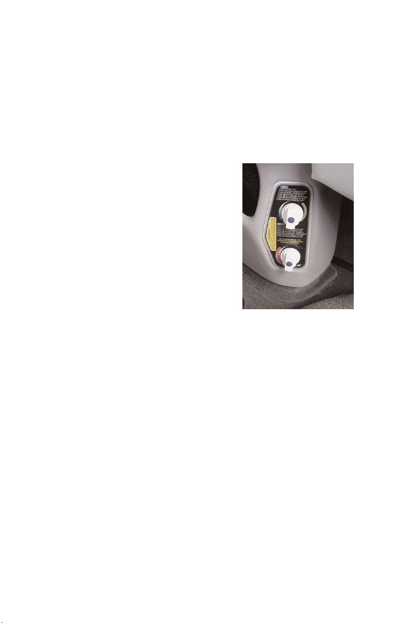
Optional Launch Control System
Your boat may be equipped with a water ballast
system that enhances the wake shape for
wakeboarding and allows you to level the boat
side to side.
There is a seacock on the bottom of the boat that
controls the water supply to the ballast system.
This valve should be in the closed position
unless you are filling or draining the ballast
system The ability to fill the Launch Control
System is controlled by valves that open and
close vent fittings on the top of each ballast tank.
To fill the ballast system, launch the boat and
open the seacock. Be certain the engine is
OFF when you open the engine box to open the seacock. Turn both control
knobs counter-clockwise to open the vents on both tanks. Fine tune the level
of water in the tanks to level the running attitude of the boat. These knobs are
located on the side console, below the radio.
Use of Launch Control System Assist Pumps
The Launch Control System assist pumps will fill and drain the Launch
Control System with the boat at rest. They don't interfere with manual filling
or draining as already described. In order to fill using the assist pumps, make
sure that the seacock and one or both of the vent control valves are open. Push
the assist pump switch.
When the tanks are full the gauges will read "full" and water will come out of
the vent thru hull to the driver's right. At that point, the pumps can be switched
off and the vents closed along with the seacock if so desired.
In order to drain the tanks with the assist pumps, the boat must be at rest or
moving slowly in the water. Make sure that the seacock and one or both of the
vent valves are open. Push the “empty” switch to pump out the water.
Please note that when the tanks are filling or draining a gurgling sound can be
heard at the vent thru hull.
1.14
Winterization of Optional Launch Control System
In order to winterize the Launch Control System only three steps need to be
taken:
1. Make sure that the system is completely drained.
2. Loosen the hose clamp on the hose attached to the seacock. Remove the
hose from the barb and allow it to drain into the bilge of the boat until no
more water is evident. Put the hose back on the hose barb and tighten the hose
clamp.
3. Put the hose back on the hose barb and tighten the hose clamp.
Folding Instructions for Optional Flight Control Tower
In order to fold the Flight Control Tower forward, grasp the knobs found under
the support structure on the port and starboard sides of the tower. Unscrew the
threaded bolts. Rock the tower forward. The tower will rest on the grab rails
of the bow section of the boat. In the folded position, it is also recommended
that the tower be securely strapped to the grab rails. In order to reposition the
tower in the upright position, simply reverse the steps.
Boarding Platform Removal
Pull the two pins that are located in the mounting brackets and lift the platform
vertically. Make sure to keep the pins attached to the brackets on the platform
so you don’t lose them. If you misplace these pins, contact your dealer for a
replacement set.
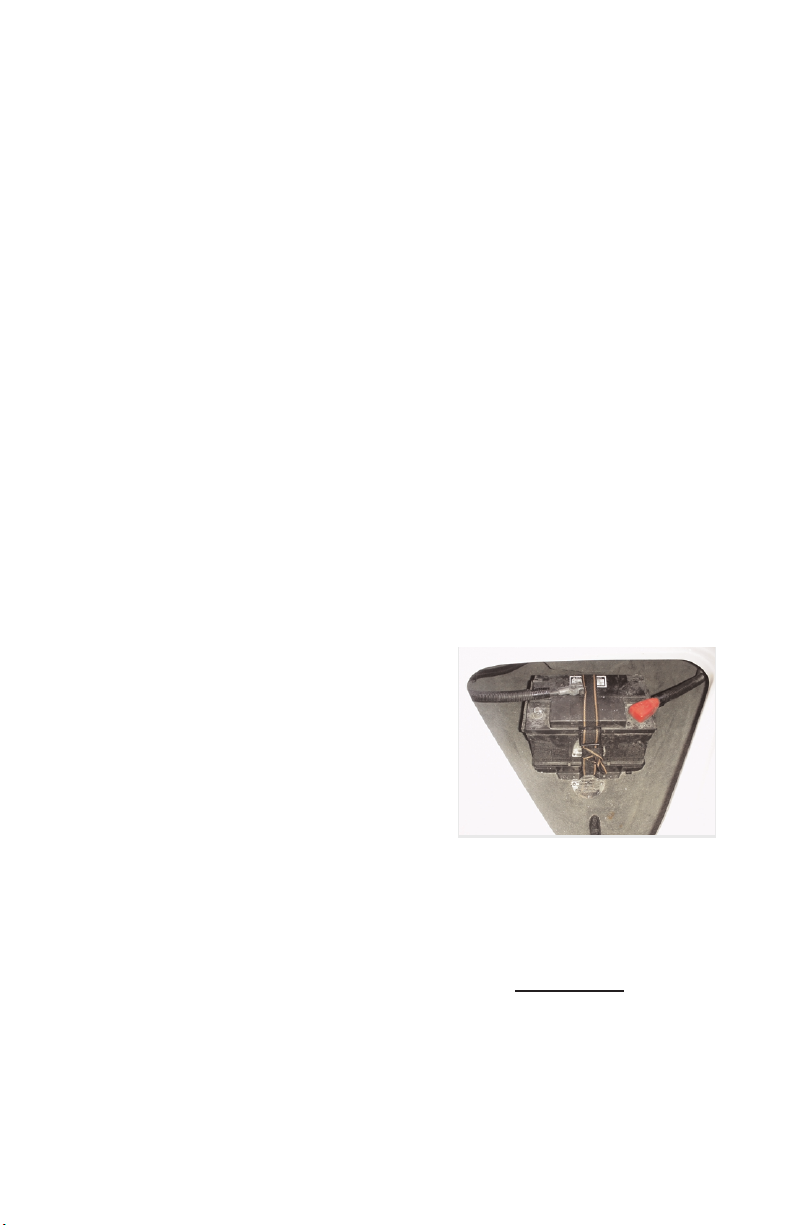
Battery Location
The battery is located under the front
cushion in the open bow.
Optional Correct Craft Cruise
Turn system ON (light blinks slowly,
indicating system is armed)
Drive to desired speed, prese ENGAGE and the system takes control of the
throttle (Light stays on steady)
Pull back on the throttle and the system disengages. (Light blinks rapidly,
indicating RESUME function is ready)
Accelerate again and the system resumes control automatically
at the last
speed used.
RESUME key feature will recall the last speed used even if the system was
shut off, completely powered down or the DISENGAGE function was used.
To go back to the previous speed, press RESUME and drive to the desired
speed.
1.15

Press both keys and the system will DISENGAGE,but remains armed. (Light
blinks slowly) This feature may be used when the operator wishes to go to
manual driving. To return to the last speed used, press the RESUME key and
drive to the desired speed. If the speed is to be changed, drive to that speed
and press engage.
INCREASE / DECREASE key can be pressed when the system is engaged to
change speed in 25 RPM increments to fine tune the speed.
User tips:
Always return to neutral and let the engine idle for two or three seconds before
turning the engine off Regularly check the black servo knob on the control unit
to make sure it is turned snugly in a clockwise direction. To do this, turn the
engine off and lift the top half of the engine box. Please note, the servo knob
cannot be moved if the engine is on.
Regularly check the set screw on the side of the black knob for tightness.
The boat speed will decrease in sharp turns. If you are towing skiers, you may
wish to manually increase the throttle or use the DISENGAGE feature to
maintain speed in sharp turns.
When towing wakeboarders, accelerate slightly past desired speed prior to
engaging the speed control.
TELEFLEX LCD SPEEDOMETER AND TACHOMETER SYSTEM
The LCD Speedometer and Tachometer system consists of a speedometer
gauge, a tachometer gauge and a speed transducer assembly.
The speedometer gauge utilizes a LCD display to provide information to the
operator and three push button switches to select the display mode. This
microprocessor-based gauge communicates with the speed transducer
assembly over a serial communication link. The speedometer receives input
via the speed transducer assembly from the two pitot tube pressure sources and
displays the highest of the two sources as the current speed.
The tachometer gauge also utilizes a LCD display and push button switch
arrangement to communicate with the operator. The engine speed input to the
gauge comes directly from the engine ignition system.
The speed transducer assembly connects the two pitot tubes via flexible tubing
and to the speedometer gauge via a four conductor cable. The transducer
converts the pressure at the pitot tubes into digital information that is sent to
the gauge for processing.
1.16
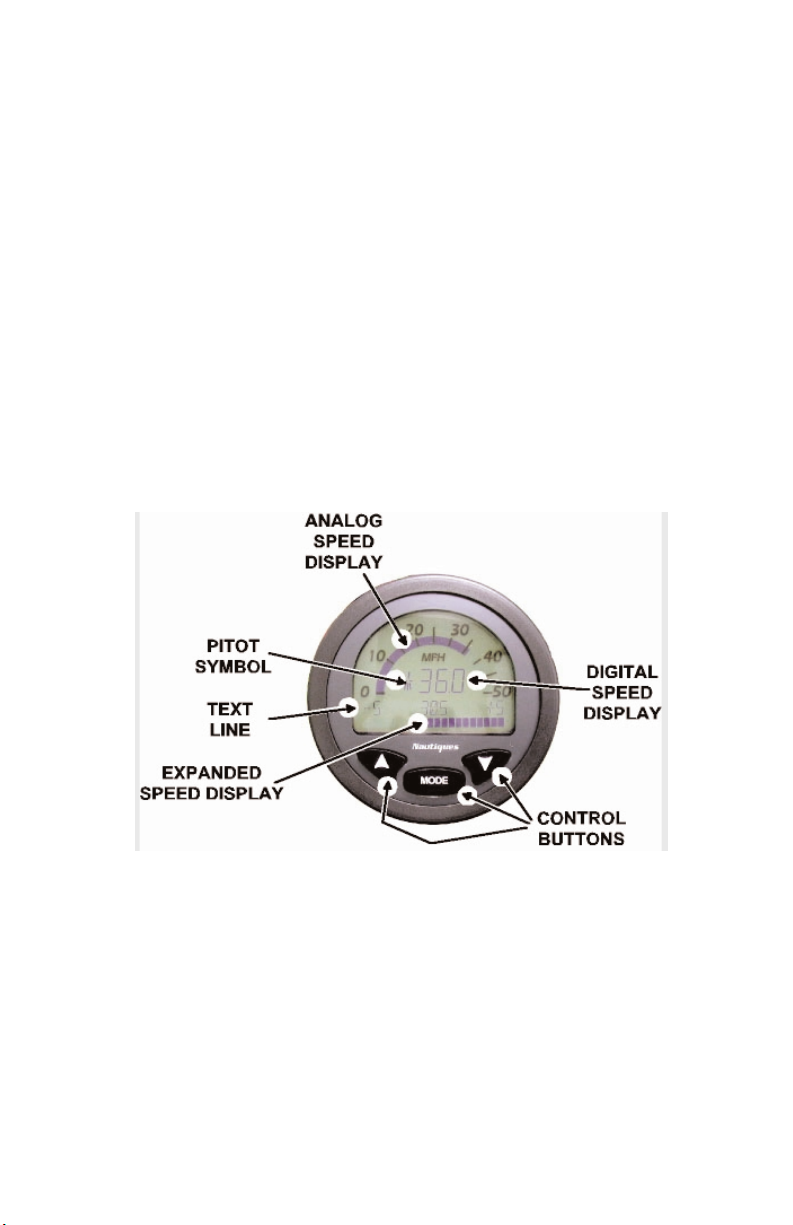
Speedometer Operation
The speedometer operates in one of three “modes”. These are “Normal
mode”, “Competition mode”, and “Calibration mode”. The operator switches
between modes using the control buttons.
The speedometer powers on in “Normal mode” with the analog speed display,
the digital speed display, and the pitot symbol active. The text line contains
“NAUTIQUES” and the expanded speed display is blank. The analog and
digital speed displays will indicate current speed and the pitot symbol will
indicate which pitot tube is being used. Pressing the mode button once will
cause the gauge to enter “Competition mode”. The analog speed display, the
digital speed display, and the pitot symbol will be active as in the “Normal
mode”. The text line will display the current speed deviation settings on the
far ends. The minus deviation setting will be displayed on the left side and the
positive setting on the right side. The current set point speed is displayed in
the center. Also, the expanded speed display will be active.
The analog and digital speed displays will indicate current speed and the pitot
symbol will indicate which pitot tube is being used. The expanded speed
display will indicate how close the current speed is to the set point speed
within the displayed plus and minus limits. If the current speed is below the
set point speed, bars in the expanded speed display will illuminate to the left
of center and if the current speed is above the set point speed, bars will
illuminate to the right of center. The number of bar segments that illuminate
is also dependent on the deviation setting.
The set point speed can be changed from the “Competition mode” by pressing
the up and down arrow buttons. Pressing an arrow button once will change the
set point speed by one tenth of a mile per hour. Pressing and holding an arrow
button will cause the set point speed to scroll in one mile per hour increments.
1.17

The deviation can be changed by pressing the mode button once while in the
“Competition mode”. The text line will display deviation X, where X is the
current deviation value. Pressing the arrow buttons will cause the deviation to
change in one mile per hour increments. The speedometer will go back to
“Competition mode” five seconds after the last button is pressed or it will go
to the “Normal mode” if the mode button is pressed before the five seconds
expire.
“Calibration mode” can be entered only from “Normal mode” by pressing both
arrow buttons simultaneously. The text line will display “Calibration X.X”
where X.X is the current calibration value. This value will change the current
speed displayed by the amount entered. The speedometer will go to “Normal
mode” five seconds after the last button is pressed or when the mode button is
pressed.
The pitot symbol indicates which pitot tube is used to display current speed
and to indicate whether or not a pitot tube is clogged. Below is a list of the
symbols and their meaning:
Port pitot tube used for display; Starboard pitot tube is functional:
Port pitot tube used for display; Starboard pitot tube clogged:
Starboard pitot tube used for display; Port pitot tube is functional:
Starboard pitot tube used for display; Port pitot tube clogged:
The set point, deviation and calibration values are stored in non-volatile
memory. When the speedometer is powered on, it will recall the last valid
values set.
1.18
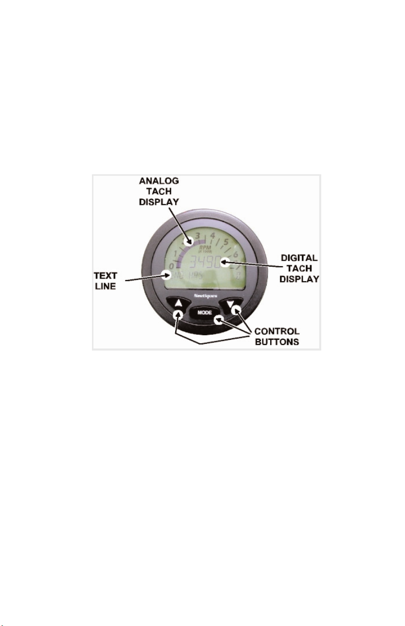
Tachometer Operations
The tachometer displays current engine speed in revolutions per minute in both
the analog and digital tach displays. The text line displays elapsed engine
hours in one-tenth hour increments. The elapsed time will only increment if
engine speed is over 400 RPM to prevent counting time when the ignition is
on but the engine is not running.
Elapsed engine hours are stored in non-volatile memory and are recalled when
the tachometer is powered on. Engine hours can not be set ahead or back.
1.19

1.20

2
2

 Loading...