

Coronis Fusion MDCC-4330, MDCC-6430 User Manual

Coronis Fusion 4MP / 6MP
User Guide
MDCC-4330, MDCC-6430
K5902108/01
12/11/2015

Barco NV
President Kennedypark 35, 8500 Kortrijk, Belgium
Phone: +32 56.23.32.11
Fax: +32 56.26.22.62
Support: www.barco.com/en/support
Visit us at the web: www.barco.com
PrintedinBelgium

Table of contents
TABLE OF CONTENTS
1. Welcome! ......... ................................................................... .............. 3
1.1 About the product ............................................................................................. 3
1.2 What’s in the box.............................................................................................. 3
2. Parts, controls and connectors ................... ............................................ 5
2.1 Display front view .... ................ ................ ................ ................ ................ ......... 5
2.2 Display rear view.............................................................................................. 6
3. Display installation ............ ............................................................ ...... 7
3.1 Removing the covers ............ ................ .................. ................ ................ ........... 7
3.2 Unlocking the height mechanism............................................................................ 8
3.3 Adjusting the display position......... ................ ................ ................ ................ ....... 9
3.4 Connecting the signal cables ................................................................................10
3.5 Connecting the power cable .................................................................................11
3.6 Routing the cables ............. ................ ................ ................ ................ ............... 11
3.7 Re-attaching the covers ......................................................................................12
3.8 VESA-mount installation .....................................................................................13
3.9 First time starting up..........................................................................................14
4. Daily operation .. ............................................................ ..................... 17
4.1 Recommendations for daily operation ....... ................ ................ ................ ............... 17
4.2 Key indicator lights................. ................ ................ ................ ................ ...........18
4.3 Standby switching.............................................................................................18
4.4 Bringing up the OSD menus .. ................ ................ ................ ................ ............... 19
4.5 Navigating through the OSD menus ......... ................ ................ .................. .............19
5. Advanced operation ........... .................................................................. 21
5.1 OSD menu language .............. ................ ................ ................ ................ ...........21
5.2 OSD menu automatic close function............... ................ ................ ................ .........21
5.3 Power status indicator light ..................................................................................21
5.4 Key indicator lights................. ................ ................ ................ ................ ...........22
5.5 Power lock function.. ................ ................ ................ ................ ................ .........22
5.6 DPMS mode.. .................. ................ ................ ................ ................ ............... 22
5.7 Hibernate................ ................ ................ ................ ................ ................ .......23
5.8 Luminance target..............................................................................................23
5.9 Color presets ............. ................ ................ ................ .................. ................ ...24
5.10 Color temperature.......... ................ ................ ................ ................ ................ ...24
5.11 Color coordinates .... ................ ................ ................ ................ ................ .........24
5.12 Viewing modes ................................................................................................25
5.13 Display functions..............................................................................................25
5.14 Ambient Light Compensation (ALC) ............. ................ ................ ................ ...........26
5.15 Reading rooms. ................ ................ ................ ................ ................ ............... 27
5.16 Continuous ALC...............................................................................................27
5.17 Embedded QA............ ................ ................ ................ ................ ................ .....28
5.17.1 About Embedded QA ...................................................................................28
5.17.2 DICOM status report ..... ................ ................ ................ ................ ............... 28
5.17.3 DICOM compliance check................... ................ ................ ................ ...........29
5.17.4 DICOM calibration.......................................................................................29
5.17.5 Reset DICOM calibration .. .................. ................ ................ ................ ...........30
5.17.6 DICOM error threshold..................................................................................30
5.18 Image scaling..................................................................................................30
5.19 Image source selection modes ... ................ ................ ................ ................ ...........30
5.20 Video input signals............................................................................................31
5.21 Grayscale conversion modes................................................................................32
5.22 EDID format .. ................ ................ ................ ................ ................ ................ .33
5.23 EDID timings...................................................................................................33
5.24 Display info ............. ................ .................. ................ ................ ................ .....33
5.25 Display status........... ................ ................ ................ ................ .................. .....34
K5902108 CORONIS FUSION 4MP / 6MP 12/11/2015
1

Table of contents
6. Cleaning your display . .................................................................... ...... 35
6.1 Cleaning instructions .........................................................................................35
7. Repackaging instructions ......................................... ............................. 37
7.1 Repacking your display.......................................................................................38
8. Important information .............................................. ............................. 39
8.1 Safety information.............. ................ ................ ................ ................ ............... 39
8.2 Environmental information ...................................................................................41
8.3 Regulatory compliance information ............ ................ ................ ................ .............43
8.4 EMC notice ........... ................ .................. ................ ................ ................ .......43
8.5 Explanation of symbols........ ................ ................ ................ ................ ...............47
8.6 Legal disclaimer...............................................................................................49
8.7 Technical specifications ......................................................................................50
8.8 Technical specifications ......................................................................................52
8.9 Open source license information ............. ................ ................ ................ ............... 54
2
K5902108 CORONIS FUSION 4MP / 6MP 12/11/2015

1. WELCOME!
1.1 About the product
Overview
Thank you for choosing this Coronis Fusion 4MP / 6MP!
1. Welcome!
Coronis Fusion 4MP / 6MP is an ingenious PACS display system designed to further enhance flexibilit
and productivity in diagnostic imaging. Featuring the industry’s first 30-inch color LCD that can be used
as two seamless heads or one wide-screen display, Coronis Fusion 4MP / 6MP offers you the freedom to
organize your workspace just the way you want it. It allows you to read CT, MR, cath and echo cardiogram
images, or any other combination, side by side on a single diagnostic screen. Coronis Fusion 4MP /
6MP features the latest, breakthrough In-Plane Switching (IPS) LCD technology. This technology brings
the most advanced LCD viewing characteristics on the market, setting new standards for
contrast, even from a wide viewing angle. Use the instructions in this guide to install your Coronis Fusion
4MP / 6MP display and discover all these interesting features yourself!
brightness and
CAUTION: Re ad all the important safety information before installing and operating your
Coronis Fusion 4MP / 6MP. Please refer to the dedicated chapter in this user guide.
1.2 What’s in the box
Overview
Your Coronis Fusion 4MP / 6MP comes with:
• this Coronis Fusion 4MP / 6MP user guide
• a documentation CD
• a system DVD
• two DisplayPort cables *
• a USB cable
• a set of AC power cords
• an external power supply
y
* If you ordered your display together with a Barco display controller that has DVI outputs, the box contains
two DVI cables.
If you ordered a Barco display controller, it’s also in the box together with its accessories. A dedicated
user guide is available on the documentation CD.
Keep your original packaging. It is designed for this display and is the ideal protection
during transport and storage.
K5902108 CORONIS FUSION 4MP / 6MP 12/11/2015 3

1. Welcome!
4 K5902108 CORONIS FUSION 4MP / 6MP 12/11/2015

2. Parts, controls and connectors
2. PARTS, CONTROLS AND
CONNECTORS
2.1 Display front view
Overview
7
1
Image 2-1
Front view
1
USB downstream connector
3
Right key
5
Standby key
7
Ambient light sensor
The key icons are displayed above the keys, adapted to the function that i t is used for
(menu dependent). See "Navigating through the O SD menus", page 19.
K5902108 CORONIS FUSION 4MP / 6MP 12/11/2015 5
2 3 5 64
2
Left key
4
Menu key
6
Power LEDs

2. Parts, controls and connectors
2.2 Display rear view
Overview
1 3 4
Image 2-2
Rear view
1
Connector compartment cover
3
Neck cover
5
DisplayPort 2 video input
7
DisplayPort 1 video input
9
USB upstream connector
2 6
5
10
7
2
+24 VDC power input
4
Display stand cover
6
DVI 2 video input
8
DVI 1 video input
8
USB downstream connectors
9 10
6
K5902108 CORONIS FUSION 4MP / 6MP 12/11/2015
3. DISPLAY INSTALLATION
Prior to installing your Coronis Fusion 4MP / 6MP and connecting all necessary cables,
make sure to have a suitable display controller physically installed in your computer. If
you are using a Barco display controller, please consult the user guide delivered with it
to do this.
For a list of compatible display controllers, please refer to the latest version of the compatibility matrix available on m
patibility Matrices > Barco Systems Compatibility Matrices).
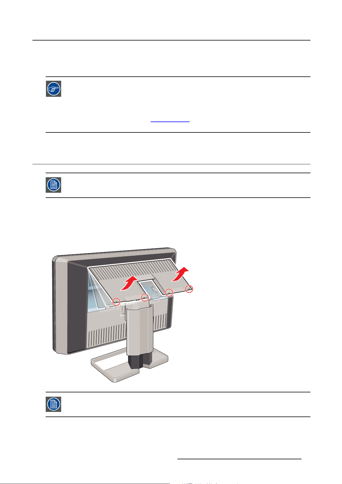
3.1 Removing the covers
The connector compartment cover should be removed to get access to the connectors.
y.barco.com (MyBarco > My Support > H ealthcare > Com-
3. Display installation
To remove th e connector compartment cover
1. Gently lift the clips at one of the handles of the connector compartment cover to release that side of the
cover.
2. Do the same at the other side of the cover.
3. Remove the cover.
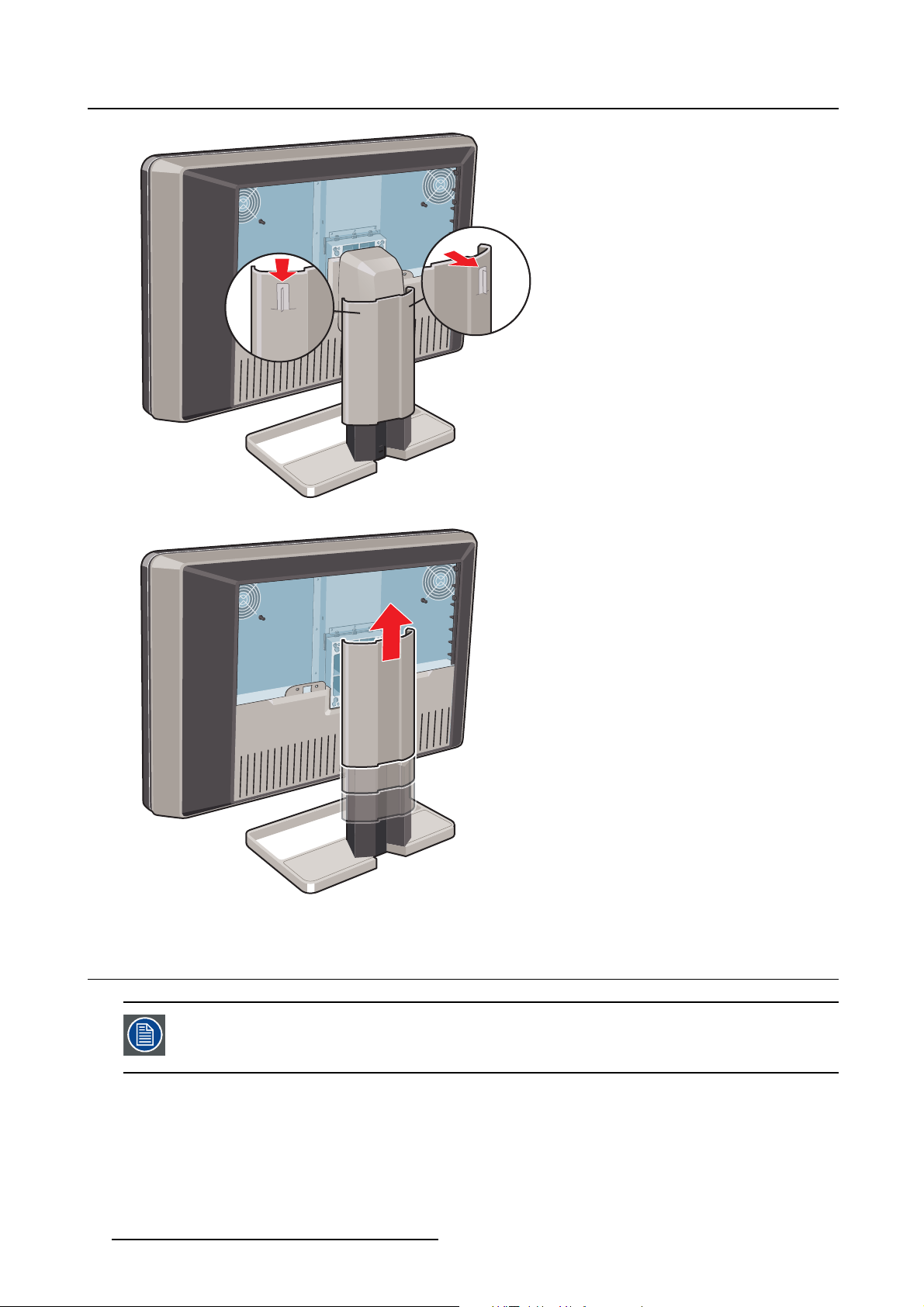
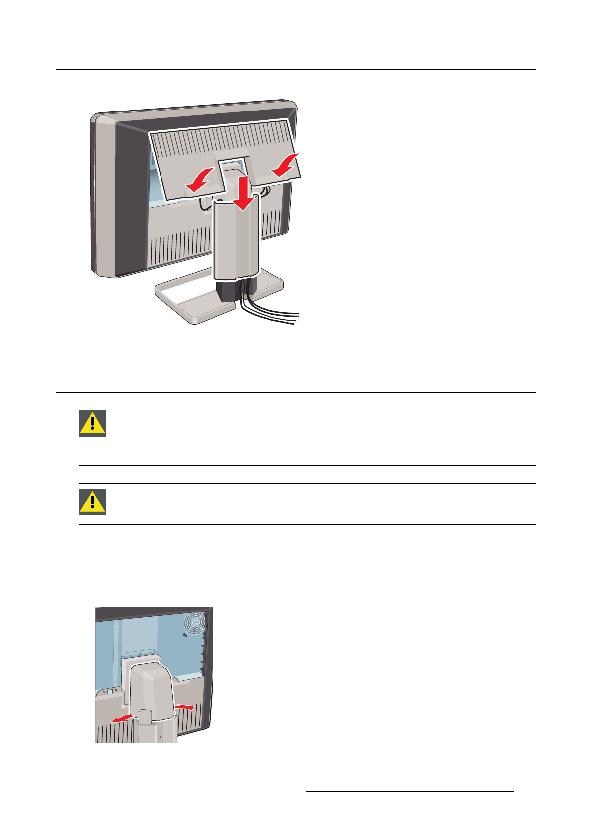
The display stand cover should be removed to get access to the cable routing channel.
To remove the display stand co
1. Gently press and hold the clips at the inside top of the cover.
K5902108 CORONIS FUSION 4MP / 6MP 12/11/2015
ver
7
3. Display installation
2. Slide the cover upwards while holding the clips pressed.
3.2 Unlocking the height mechanism
In the factory, the height-positioning system in the display stand is locked with a red
hook to prevent damage during transportation. You’ll have to remove this hook before
adjusting your display height position.
To remove the hook:
1. Position the display with its rear side facing you.
2. While holding the display panel pushed down, pull out the red hook in the display stand.
8
K5902108 CORONIS FUSION 4MP / 6MP 12/11/2015
3. Display installation
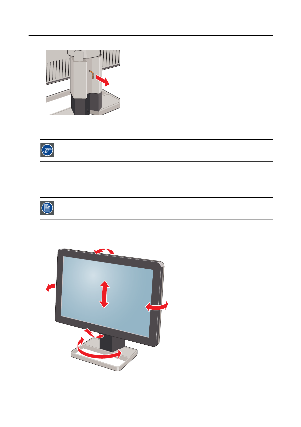
3. Keep the clip in the dedicated hole in case the display needs to be shipped later.
To retain the hook for possible future transportation, insert the short, red end of the
hook back into the stand of your display.
3.3 Adjusting the display position
Now that the height-positioning system of your display is unloc
display position.
To adjust the display position
1. Tilt, swivel, raise and lower the display as desire
d.
ked, you can adjust the
K5902108 CORONIS FUSION 4MP / 6MP 12/11/2015 9
3. Display installation
CAUTION: Do not try to pivot your display when attached to the stand. Trying to do so
could cause s erious damage to your display and its stand.
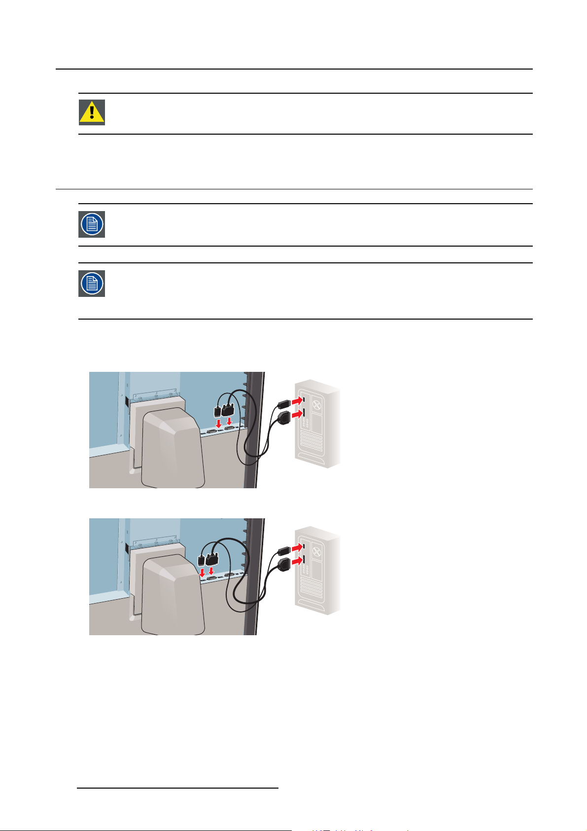
3.4 Connecting the signal cables
To get access to the connectors, remove the connector compartment cover. See "Removing the covers", page 7 .
Each side of your display can have a different video input connected (one side can have
DVI connected while the other side has DisplayPort connected). Both display sides can
have the s ame video input connected as well but only one video input is allowed on each
side of your display.
To connect the signal cables to the display:
1. Connect one head of the display controller to the DVI 1 or DisplayPort 1 connector with one of the
supplied DVI or DisplayPort cables.
2. Connect another head of the display controller to the DVI 2 or DisplayPort 2 connector with one of the
supplied DVI or DisplayPort cables.
3. If you want to make use of your display’s USB downstream connectors, connect a PC USB downstream
connector to the display’s USB upstream connector by means of the supplied USB 2.0 cable.
10
K5902108 CORONIS FUSION 4MP / 6MP 12/11/2015

3. Display installation
3.5 Connecting the po w er cable
To connect the power cable to the display:
1. Connect the supplied external DC power supply to the +24 VDC power input of your Coronis Fusion
4MP/6MPdisplay.
2. Plug the other end of the external DC power supply into a grounded po
power cord delivered in the packaging.
wer outlet by means of the proper
3.6 Routing the cables
To route the cables
1. Route all connected cables through the cable routing channel in the stand of your display.
K5902108 CORONIS FUSION 4MP / 6MP 12/11/2015
11

3. Display installation
Tip: The cable straps at the inside of the connector compartment allow you to fix the cables for better
shielding of the cables.
3.7 Re-attaching the covers
To re-attach the display stand cover
1. Slide the display stand cover downward. You’ll hear a “click” sound of the cover’s clips when the display
stand cover is in position.
Pay attention that all cables stay in the c able channel while re-attaching the cover.
To re-attach the connector compartment cover
1. Slide the cover’s top in position and then push the cover’s bottom. You’ll hear a “click” sound of the
cover’s clips when the connector compartment cover is in position.
12
K5902108 CORONIS FUSION 4MP / 6MP 12/11/2015
3. Display installation
3.8 VESA-mount installation
WARNING: Use an arm that is approved by VESA (according to the VESA 100 mm stan-
dard).
Use an arm that can support the weight of the display. Refer to the technical s pecifications of this display for the applicable weight.
CAUTION: You should mount the panel in landscape position. Portrait position is pos-
sible but not supported.
Overview
The panel, standard attached to a stand, is compatible with the VESA 100 mm standard. Thus, it can be
used with an arm that is approved by VESA. This chapter shows you how to release the panel from the
stand and how to attach it to an arm. If you
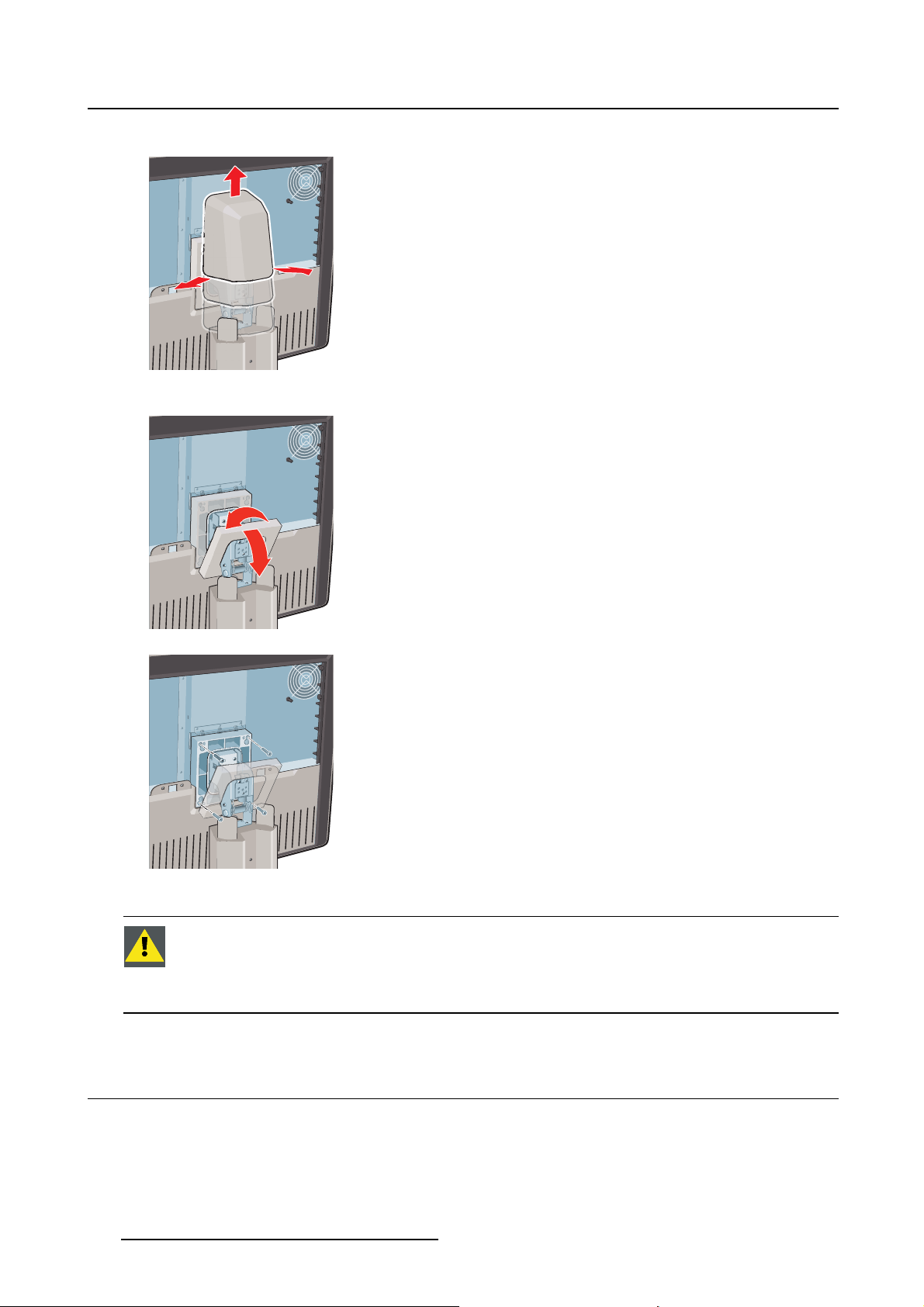
1. Gently pull open both lower sides of the cover.
’renotusinganarm,youcanskipthischapter.
K5902108 CORONIS FUSION 4MP / 6MP 12/11/2015 13
3. Display installation
2. Slide the cover upwards while holding the lower sides pulled open.
3. Lift the plastic frame that covers the fixation of the panel to the stand. Turn it for 45 degrees to uncover
the fixation screws.
4. Unscrew the four fixation screws fixing the panel to the stand.
5. Attach the panel firmly to the arm using 4 screws M4 x 10 mm.
WARNING: Never move a display attached to an arm by pulling or pushing the display
itself. I nstead, make sure that the arm is equipped with a VESA approved handle and
use this to mov e the display.
Please refer to the instruction manual of the arm for more information and instructions.
3.9 First time starting up
Overview
You are now ready to start up your Coronis Fusion 4MP / 6MP for the first time.
14
K5902108 CORONIS FUSION 4MP / 6MP 12/11/2015

3. Display installation
1. Switch on your Coronis Fusion 4MP / 6MP as described in "Standby switching", page 18.
2. Turn on the computer connected to your display .
If you have properly installed your display and display controller, the Windows start-up messages will
appear once the boot procedure is finished.
Your Coronis Fusion 4MP / 6MP display will be running in a basic video mode at a default refresh rate when first time starting up. If you are using a Barco display controlle r,
please consult the dedicated user guide available on the system CD to install the drivers,
software and documentation. When this is done, your display will automatically detect
the connected video input signal(s) and apply the correct video mode and refresh rate.
K5902108 CORONIS FUSION 4MP / 6MP 12/11/2015 15

3. Display installation
16 K5902108 CORONIS FUSION 4MP / 6MP 12/11/2015
 Loading...