

Page 1

File : CS-SUP-MUTI-WTHERMAPP-E01.sxw
WaveTherm modules – application handbook page 1 of 65
Page 2

File : CS-SUP-MUTI-WTHERMAPP-E01.sxw
REVISIONS HISTORY
Rev. # Description Author Date Comments
1 Original document RCS 02/02/05 Version 1
2 Addon text FCC RCS 17/02/05 Version 2
SUPPORTED FIRMWARE VERSION
➢ WaveTherm - DALLAS
European Version
Manual version Firmware version Date
1.0 V 01.04 15/10/04
US Version
Manual version Firmware version Date
1.0 V 81.05 15/10/04
➢ WaveTherm - PT100
Manual version Firmware version Date
1.0 V 01.02 15/10/04
➢ WaveTherm - PT1000
Manual version Firmware version Date
1.0 V 01.00 15/10/04
This device complies with part 15 of the FCC rules. Operation is subject to the
following two conditions : this device may not cause harmful interference, and
this device must accept any interference received, including interference that
may cause undesired operation.
Caution : any changes or modifications not expressly approved by CoronisSystems could void the user's authority to operate the equipment.
WaveTherm modules – application handbook page 2 of 65
Page 3

File : CS-SUP-MUTI-WTHERMAPP-E01.sxw
TABLE OF CONTENTS
1 PRESENTATION........................................................................................................................... 6
2 REFERENCE DOCUMENTS......................................................................................................... 6
3 PRESENTATION OF THE WAVETHERM MODULES FUNCTIONALITIES................................ 7
3.1 SENSORS INTERFACE.........................................................................................................................7
3.2 READ TEMPERATURES.......................................................................................................................8
3.3 PERIODIC TEMPERATURE READING (DATALOGGING)..................................................................8
3.4 MANAGEMENT OF THRESHOLD ALARMS........................................................................................9
3.4.1 Threshold Alarm Detection.............................................................................................................9
3.4.2 Storage of Threshold Alarm occurences........................................................................................9
3.4.3 Transmission of a Threshold Alarm Frame.....................................................................................9
3.5 STORAGE OF CALIBRATION PARAMETERS..................................................................................10
3.6 WAKE-UP SYSTEM MANAGEMENT..................................................................................................10
3.7 AUTOMATIC TRANSMISSION OF FAULTS......................................................................................10
3.8 SENSOR FAULT DETECTION (IF SUPPORTED BY THE MODULE)............................................... 11
3.9 END OF BATTERY LIFE DETECTION................................................................................................11
4 DATA EXCHANGE PRINCIPLE WITH A WAVETHERM MODULE .......................................... 12
5 INFORMATION RELATIVE TO THE PROBES ASSOCIATED WITH THE WAVETHERM
MODULES ...................................................................................................................................... 15
5.1 DALLAS PROBES...............................................................................................................................15
5.1.1 Coding of temperatures for the DALLAS probe type DS18B20 ...................................................15
5.1.2 Probe ID........................................................................................................................................15
5.1.3 Setting of the probe coefficient parameters..................................................................................16
5.2 PT100 AND PT1000 PROBES.............................................................................................................17
5.2.1 Representation of temperature values..........................................................................................17
5.2.2 Calibration of radio module...........................................................................................................18
5.2.3 Setting of probe coefficient parameters........................................................................................19
6 MODIFICATION OF THE INTERNAL PARAMETERS................................................................21
6.1 INTERNAL PARAMETERS LIST ACCESSIBLE BY RADIO COMMANDS....................................... 21
6.1.1 Parameters common to all WAVETHERM versions.....................................................................21
6.1.2 Parameters specific to the WaveTherm – DALLAS module.........................................................22
6.1.3 Parameters specific to the WaveTherm – PT100 module............................................................22
6.1.4 Parameters specific to theWaveTherm – PT1000 module...........................................................23
6.1.5 Definition of the module control bytes...........................................................................................24
6.2 PRINCIPLE OF READING AND WRITING OF INTERNAL PARAMETERS......................................25
WaveTherm modules – application handbook page 3 of 65
Page 4

File : CS-SUP-MUTI-WTHERMAPP-E01.sxw
7 WAVETHERM MODULE FUNCTIONS ...................................................................................... 27
7.1 PARAMETER SETTING OF THE WAVETHERM MODULE...............................................................27
7.1.1 Reading of the module type..........................................................................................................27
7.1.2 Reading of the firmware version...................................................................................................28
7.1.3 Reading of the date and time of the module.................................................................................29
7.1.4 Setting the date and time of the module.......................................................................................30
7.1.5 Access to the user data area........................................................................................................31
7.1.6 Initialization of the sensors............................................................................................................33
7.2 READING THE CURRENT VALUE OF THE TEMPERATURE SENSORS........................................34
7.2.1 Information concerning precision..................................................................................................34
7.2.2 Description of the commands to be used.....................................................................................34
7.2.3 Reading the current ohmic values of the sensors.......................................................................36
7.3 WAKE-UP SYSTEM MANAGEMENT..................................................................................................37
7.3.1 Description of the parameters used..............................................................................................37
7.3.2 Choice of wake-up mode..............................................................................................................37
7.3.3 Set a new wake-up period............................................................................................................38
7.3.4 Set a fixed wake-up period for certain days of the week..............................................................38
7.3.5 Set day/night system parameter without distinction of days of the week.................................... 38
7.3.6 Set the day/night system parameters according to day of the week...........................................40
7.4 PARAMETER SETTING OF THE DATALOGGING MODE................................................................41
7.4.1 Description of the parameters used..............................................................................................41
7.4.2 Precision level of the measurement..............................................................................................41
7.4.3 Activating the datalogging mode...................................................................................................42
7.4.4 Index logging in time steps...........................................................................................................43
7.4.5 Index logging once a week...........................................................................................................44
7.4.6 Index logging once a month..........................................................................................................45
7.4.7 Reading the logged temperature values.......................................................................................46
7.5 ADVANCED DATALOGGING.............................................................................................................48
7.5.1 Description of the parameters used..............................................................................................48
7.5.2 Parameter setting of the Advanced Datalogging mode................................................................49
7.5.3 Principle of reading the temperature, and re-initializing the storage table....................................49
7.5.4 Reading the totality, or a part of the storage table........................................................................51
7.5.5 Structure of the data when two sensors are activated..................................................................54
7.5.6 Usage limit of the multi-frame mode.............................................................................................55
7.6 MANAGEMENT OF THRESHOLD ALARMS......................................................................................56
7.6.1 Description of the parameters used..............................................................................................56
7.6.2 Precision level of the measurement..............................................................................................57
7.6.3 Format of the temperature information.........................................................................................57
7.6.4 Principle of the detection modes...................................................................................................58
7.6.5 Selection of the threshold detection modes, and activation of the detection................................59
WaveTherm modules – application handbook page 4 of 65
Page 5

File : CS-SUP-MUTI-WTHERMAPP-E01.sxw
7.6.6 Configuration of the measurement period of the threshold detection...........................................59
7.6.7 Reading the threshold detection table..........................................................................................60
7.7 MANAGEMENT OF THE ALARM FRAMES........................................................................................61
7.7.1 Description of the parameters used..............................................................................................61
7.7.2 Configuration of the route to reach the alarm frames recipient.................................................... 61
7.7.3 Configuration of the alarms to be sent..........................................................................................62
7.7.4 Triggering an alarm frame............................................................................................................63
7.8 END OF BATTERY LIFE DETECTION................................................................................................64
7.8.1 Description of the parameters used..............................................................................................64
APPENDIX A : SET OF THE APPLICATIVE COMMANDS.............................................................................65
WaveTherm modules – application handbook page 5 of 65
Page 6

File : CS-SUP-MUTI-WTHERMAPP-E01.sxw
1 PRESENTATION
This document describes the functionalities of WaveTherm radio modules :
WaveTherm – DALLAS Used with DALLAS sensor
WaveTherm – PT100 Used with PT100 sensor
WaveTherm – PT1000 Used with PT1000 sensor
This document defines in an exhaustive way the applicatives data relating to serial dialog frames between a
Wavecard and a host equipment , used to reach the data of the WaveTherm radio module.
2 REFERENCE DOCUMENTS
Ref Title Reference Version Date
DR[1] WaveCard user handbook
WaveTherm modules – application handbook page 6 of 65
Page 7

File : CS-SUP-MUTI-WTHERMAPP-E01.sxw
3 PRESENTATION OF THE WAVETHERM MODULES FUNCTIONALITIES
3.1 SENSORS INTERFACE
➢ WaveTherm – DALLAS :
The module is designed to manage to the maximum two DALLAS temperature sensors (type
DS18B20).
This DALLAS sensor of 1-wire type integrates a 12-bit internal converter.
Each external sensor is connected to the module by a cable equipped with a BINDER connector of
3-pin type.
An automatic identification of the temperature sensors allows to memorize the identifier of the
sensors. This phase is automatically carried out when powering the module
and is also activated on a specific radio request (in this case, The module returns by radio the
identifiers of the sensors).
➢ WaveTherm – PT100 :
The WaveTherm-PT100 module has the possibility to manage 1 or 2 PT100 temperature sensors.
The probes are connected to the module through impervious connectors allowing to connect 2, 3 or 4
wires probes.
➢ WaveTherm – PT1000 :
The WaveTherm-PT1000 module has the possibility to manage 1 or 2 PT1000 temperature sensors.
The probes are connected to the module through impervious connectors allowing to connect 2, 3 or 4
wires probes.
WaveTherm modules – application handbook page 7 of 65
Page 8

File : CS-SUP-MUTI-WTHERMAPP-E01.sxw
3.2 READ TEMPERATURES
The WaveTherm module has the following possibilities:
To read the current temperature ;
To transmit the last N temperatures stored, in one frame.
If two temperature sensors are used, then the WaveTherm return the last N/2 values of each sensor.
• WaveTherm – DALLAS : N = 48 temperatures
• WaveTherm – PT100 : N = 24 temperatures
• WaveTherm – PT1000 : N = 24 temperatures
3.3 PERIODIC TEMPERATURE READING (DATALOGGING)
Periodic reading of temperatures is available in two versions. In both cases, the module may be configured to
store the temperatures measured periodically (in time intervals ranging from a minute to several hours), once
a week or once a month.
➢ Standard datalogging :
Periodic collection of temperature measurements up to N temperatures. In this case, it functions in
'permanent loop' mode, i.e. the most recent measurements replace the oldest measurements.
WaveTherm – DALLAS : N = 48 temperatures;
WaveTherm – PT100 : N = 24 temperatures;
WaveTherm – PT1000 : N = 24 temperatures.
➢ Advanced datalogging:
Periodic collection of temperature measurements up to M temperatures. In this case, it functions in
'stop memory full' mode.
WaveTherm – DALLAS : M = 4500 temperatures;
WaveTherm – PT100 : M = 2000 temperatures;
WaveTherm – PT1000 : M = 2000 temperatures.
Remark : Only the 'Stop memory full' mode is currently operational : when the memory corresponding to N
temperatures is full, datalogging stops automatically.
A new parameter setting cycle must then be started with a specific radio command.
A future upgrade will enable permanent looping with indication of looping.
WaveTherm modules – application handbook page 8 of 65
Page 9

File : CS-SUP-MUTI-WTHERMAPP-E01.sxw
3.4 MANAGEMENT OF THRESHOLD ALARMS
The WaveTherm module detects when the values exceed the threshold levels (high or low) for a given period
of time.
The WaveTherm – PT100 and PT1000 may be configured with a precision level offering a more reliable
measurement even in environments with excessive interference (see chapter 7.2.1).
Three types of threshold alarm detection methods may be programmed :
immediate threshold alarm detection
threshold alarm detection for a given continuous period of time (successive mode)
threshold alarm detection for a total period of time (cumulative mode)
3.4.1 Threshold Alarm Detection
Threshold alarm detection requires periodic measurement of the temperature for a predefined period. The
value of this period enables establishment of the threshold alarm detection reactivity.
This period is set independent of the datalogging period. However, for power saving reasons, it is
recommendable to set the datalogging period as a multiple of the threshold alarm detection period.
The following parameters apply to this function:
High threshold alarm,
Low threshold alarm,
Threshold excess time (used in cumulative and successive mode),
Mode parameter setting byte (high threshold enabled, low threshold enabled, immediate,
successive or cumulative mode).
3.4.2 Storage of Threshold Alarm occurences
Threshold alarms are stored in a memory zone which may be accessed by radio. If the number of threshold
alarms exceeds the memory storage capacity, the oldest alarms recorded are deleted.
The following information is recorded in the table:
Threshold alarm detection date
Threshold alarm detection duration
The average value of all measurements recorded during the alarm period.
3.4.3 Transmission of a Threshold Alarm Frame
The module may be programmed to transmit a radio frame as soon as a threshold alarm is detected.
WaveTherm modules – application handbook page 9 of 65
Page 10

File : CS-SUP-MUTI-WTHERMAPP-E01.sxw
3.5 STORAGE OF CALIBRATION PARAMETERS
The WaveTherm module manage a non-volatile memory area accessible by radio command, and allowing to
store up to 32 bytes.
This area is not used by the internal process, and is generally used to store the parameters relative to the
calibration of the module, and can be read, or modified by specifying the start address, and the size of the
data.
3.6 WAKE-UP SYSTEM MANAGEMENT
In order to reduce module power consumption, a wake-up period parameter setting system is incorporated.
This system enables modification of the module wake-up period (default setting 1 s) by entering a time and
day of the week :
The wake-up period default value may be modified;
Two time-windows with different wake-up periods may be defined;
Each day of the week may be set in one of the following three cases :
• Wake-up period default setting
• Wake-up according to predefined time windows
• No wake-up period (for safety reasons, the module is not disabled on reception and it
wakes up every 10 seconds)
Note : The system is disabled by default and must be enabled by writing a specific profile in the
wake-up system status word.
3.7 AUTOMATIC TRANSMISSION OF FAULTS
The WaveTherm module offers the possibility to automatically transmit radio frames when an occurrence is
detected.
The following occurrences may provoke an automatic alarm:
Threshold detection (see chapter 7.6)
End of battery life detection (see chapter 7.8)
Probe fault detection (WaveTherm – PT100 and PT1000 only)
It is possible to select for each type of occurrence whether or not an alarm frame is to be sent.
The radio address of the receiver module and the repeater path must be preset with a radio signal.
WaveTherm modules – application handbook page 10 of 65
Page 11

File : CS-SUP-MUTI-WTHERMAPP-E01.sxw
3.8 SENSOR FAULT DETECTION (if supported by the module)
For all modules, temperature probe absence or error detection is carried out during a write request and is
indicated by the presence of a specific value which does not correspond to a possible temperature value.
However, in the case of the WaveTherm – PT100 and WaveTherm – PT1000 modules only, after
detection of a probe fault, the module carries out the following operations:
records the detection date in internal parameters (0x91 ; 0x92).
If required, transmits an immediate probe fault detection radio frame.
3.9 END OF BATTERY LIFE DETECTION
To detect the end of battery life, the WaveTherm module uses the power metering principle rather than
measurement of the battery voltage. Lithium batteries are, in particular during passivation, unsuitable for the
voltage measurement method to determine the remaining capacity.
The WaveTherm records and evaluates all events (measurements, transmissions) to decrement the power
meter according to the battery used. When the meter passes below a predefined threshold, the “end of
battery life” is signalled with the Application Status byte.
The initial value of the end-of-life meter is factory-set. It depends on the type and number of batteries used.
When the end of battery life is detected, the detection date is memorised and may be read with a radio
command.
Please refer to the WaveTherm module technical specifications, for more details on the life of the modules.
WaveTherm modules – application handbook page 11 of 65
Page 12

File : CS-SUP-MUTI-WTHERMAPP-E01.sxw
4 DATA EXCHANGE PRINCIPLE WITH A WAVETHERM MODULE
The WaveTherm module uses the WAVENIS protocol.
The choice of mode used is initiated by the read element which uses a different set of commands (see
WaveCard document) when sending commands to the WaveCard.
The following chart indicates the read modes possible as well as their typical applications.
Read mode Description Recommendations
Peer-to-peer Individual reading with re-transmission management
in case of no reply
Standard use
Polling This mode enables successive polling of several
modules in a single operation .
The principle consists of waking up several modules
with the 1st radio transmission.
To be used when module reading time is
an important factor.
Re-transmission not possible.
Broadcast and multicast (*) This mode enables use of a single frame to address
all radio modules within reception range.
The multicast mode may only address one group of
modules.
This mode enables reading of modules
without knowing their radio address.
Type of use: detection of radio modules
within range of the emitter module
(installation phases).
➢ Additional functions:
Additional
functions
Compatibility Description Recommendations
Repeater Only used in point-
to-point mode.
This function enables use of a radio module to relay
a frame which was not initially intended for this
module.
This is a default function of the WaveTherm module,
i.e. it may be read via several repeaters but may
also act as a repeater itself when reading another
unit.
This function is used when the caller
module and the target WaveTherm
module are outside radio range.
The maximum number of repeaters is
limited to 3.
Attention: collection of data in multi-frame mode (advanced datalogging) is not possible in
repeater mode.
WaveTherm modules – application handbook page 12 of 65
Page 13
File : CS-SUP-MUTI-WTHERMAPP-E01.sxw
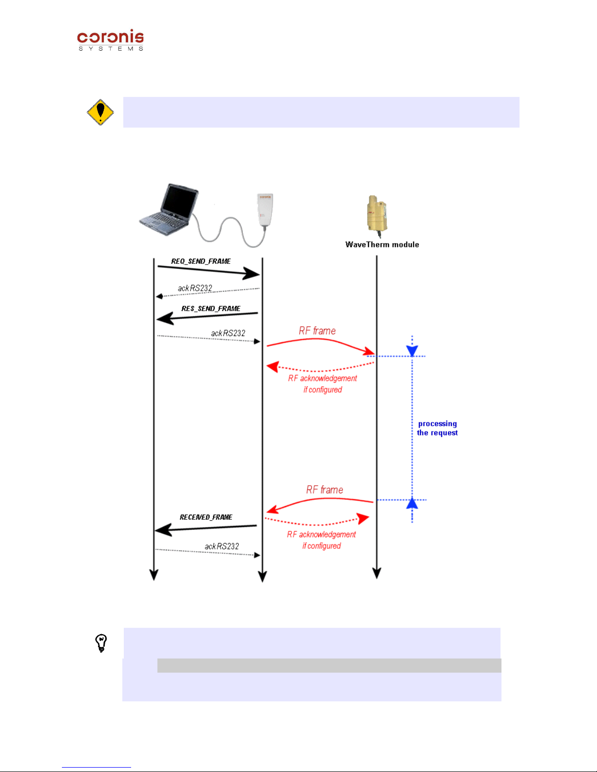
➢ Example in Point-to-point mode :
Remark : Generally, the exchanges examples given in this document will be in Point-to-point mode,
except when the context depends directly on the mode of exchanges.
This type of radio exchange allows to send a request, then to await a response of the remote equipment.
Note : the commands of Point-to-point exchanges, have the following format: (all the exchanges
modes are treated in document [DR1])
CMD NAME DESCRIPTION
0x20 REQ_SEND_FRAME
Request to send a radio frame with the waiting for the radio response.
0x30 RECEIVED_FRAME
Received radio frame by the radio board.
WaveTherm modules – application handbook page 13 of 65
Page 14

File : CS-SUP-MUTI-WTHERMAPP-E01.sxw
The data field of each command must be formatted according to the following table :
CMD
DATA
6 bytes variable ( max : 152 bytes)
0x20
Radio address from equipment to reach
Data to transmit
0x30
Radio address from transmitter
equipment
Received Data
the first byte of the field 'data to transmit' (or 'Received Data') contains an applicative command (or its
acknowledgement). That allows to the receptor of the frame to identify the type of requests (or of responses).
Data to Transmit or Received Data
1 byte 151 bytes
REQ_SEND_FRAME Applicative command Data relating to the request
RECEIVED_FRAME
Acknowledgement of the
applicative command
Data relating to the response
The commands set is available in Appendix A.
ATTENTION, This document describes only the format of the fields 'Data to Transmit', 'Received Data'.
These fields are directly dependent on the access to the functionalities of the WaveTherm modules. The
other fields of the radio frame depend on the exchanges modes chosen, and are detailed in document
[DR1].
WaveTherm modules – application handbook page 14 of 65
Page 15

File : CS-SUP-MUTI-WTHERMAPP-E01.sxw
5 INFORMATION RELATIVE TO THE PROBES ASSOCIATED WITH THE
WAVETHERM MODULES
5.1 DALLAS Probes
5.1.1 Coding of temperatures for the DALLAS probe type DS18B20
These probes have a resolution of 12 bits and their value is coded on two bytes (MSB first)
Negative values are expressed in two's complements with addition of a sign.
MSB LSB MSB LSB
Most Significant Byte Leasr Significant Byte
b7 b6 b5 b4 b3 b2 b1 b0 b7 b6 b5 b4 b3 b2 b1 b0
S S S S 2
7
2
6
2
5
2
4
2
3
2
2
2
1
2
0
2
-1
2
-2
2
-3
2
-4
Unit : Celsius degree (°C)
Bits [b7:b3] : sign bit.
Remark: The hexadecimal value 0x4FFF indicates the absence of a probe, or a connection error between
the module and the probe.
Some temperature values:
Temperature Binary value (MSB First) Hexadecimal value
+125°C 0000 0111 1101 0000 0x07D0
+85°C 0000 0101 0101 0000 0x0550
+25°C 0000 0001 1001 0000 0x0190
0°C 0000 0000 0000 0000 0x0000
-10.125°C 1111 1111 0101 1110 0xFF5E
-55°C 1111 1100 1001 0000 0xFC90
5.1.2 Probe ID
The probe ID corresponds to a unique code attributed to each DALLAS temperature probe in the factory.
This code is composed of 8 bytes defined as follows:
MSByte LSByte
1 byte 6 bytes 1 byte
Family Code Serial n° (48 bits) CRC Code
The family code is used to distinguish between the probes used:
Probe DS18S20 : 0x10
Probe DS18B20 : 0x28
WaveTherm modules – application handbook page 15 of 65
Page 16

File : CS-SUP-MUTI-WTHERMAPP-E01.sxw
5.1.3 Setting of the probe coefficient parameters
The precision of DALLAS probes is indicated by the manufacturer as ±0.5°C (-10°C to +85°C) and requires
no calibration before use.
However, it is possible to improve this precision if the user wishes to calibrate the probe. In this case, the
WaveTherm module contains a 32-byte memory zone for storage of transfer coefficients after calibration.
Initially, two parameters was created (size: 2 bytes per parameter), each one being able to store the value of
a coefficient of transfer.
After calibration, this allowed to refine measurement with a 2 degrees polynomial to the maximum.
Thereafter, a more important memory area was implemented, in order to store user data. Users can use this
area for whatever they want, but in order to increase the measurement precision, this 32-bytes area allows to
store a more significant number of coefficients.
Consequently the polynomial used can be superior degrees to 2; and allows to obtain a finer sleeking of
information. Management of this memory area is described further in chapter 7.1.5.
Remark : To maintain compatibility with old versions of the modules (Is)Thermeter), the storage
parameters of the coefficients are always existing, and are accessible by commands of reading and
writing of internal parameters.
Parameter 0x25 : parameter A relating to sensor 1
Parameter 0x26 : parameter B relating to sensor 1
Parameter 0x27 : parameter A relating to sensor 2
Parameter 0x28 : parameter B relating to sensor 2
WaveTherm modules – application handbook page 16 of 65
Page 17
File : CS-SUP-MUTI-WTHERMAPP-E01.sxw
5.2 PT100 and PT1000 probes
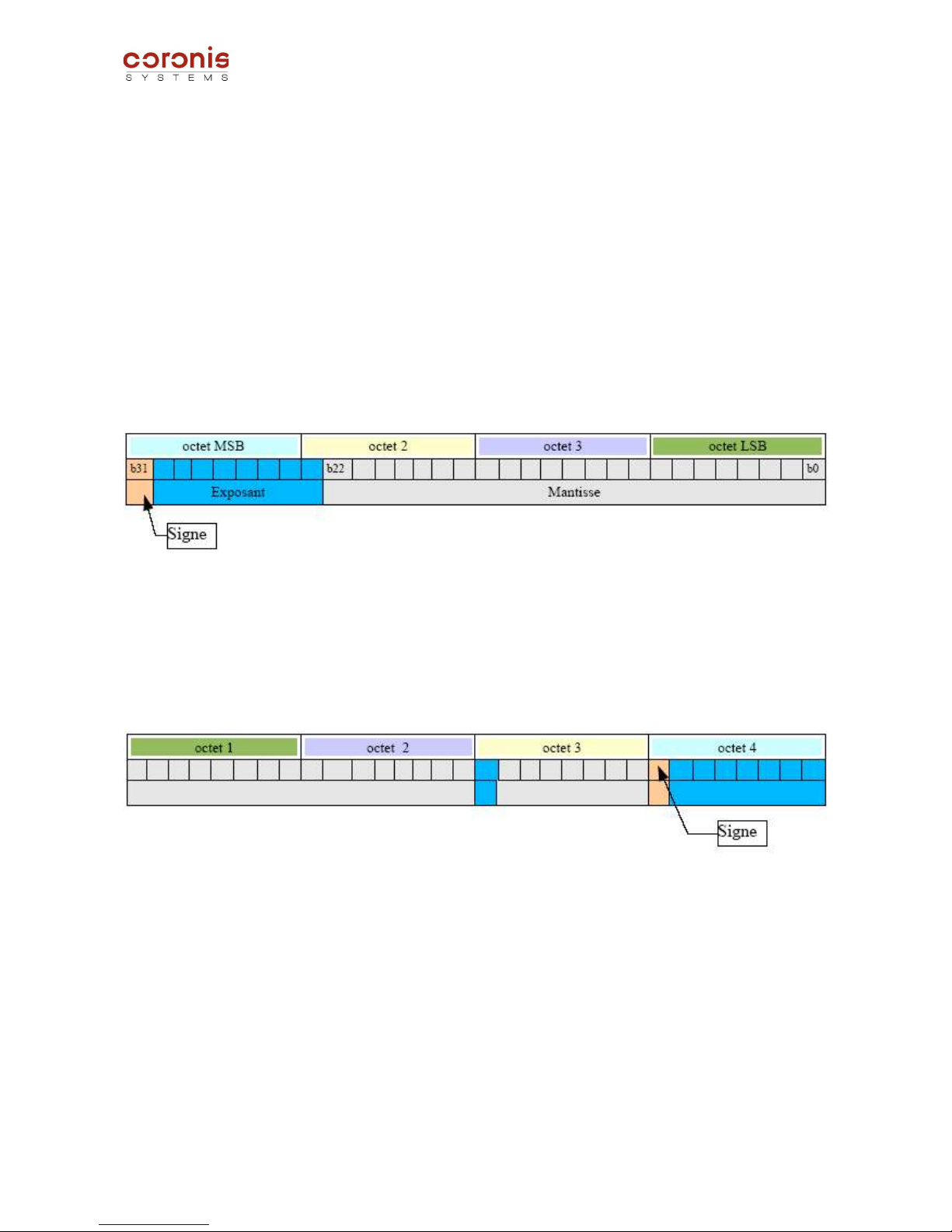
5.2.1 Representation of temperature values
Due to the high level of precision required of the temperature values processed by the module,
WaveTherm PT100 or PT1000 are true numbers (with a mantissa and exponent).
They are represented in the form of a 32-bit floating number.
The format used is the standard IEEE format with precision coded on 32 bits (+/-5.8774e-39 to
+/- 170,14e36)
➢ Theoretic representation of a floating IEEE 32-bit in bytes :
➢ Representation of the floating numbers in the radio buffer:
The radio module represents the 32-bit floating data in its buffers by coding them in LSB first. This is the
standard representation format used by the compilers C/C++ on PC.
A shift of the exponent allow to code it from E-127 to E+128
WaveTherm modules – application handbook page 17 of 65
Page 18

File : CS-SUP-MUTI-WTHERMAPP-E01.sxw
5.2.2 Calibration of radio module
➢ Factory calibration
The precision of PT100 and PT1000 probes is such that the WaveTherm module measurement chain
requires calibration.
This calibration is carried out automatically in the factory and the product is supplied ready for use.
➢ Re-calibration on site
Re-calibration on site is possible under certain conditions.
To carry out this operation, it will be necessary to connect two calibration precision resistances.
Remark: Calibration is therefore only possible on WaveTherm PT100 (or PT1000) modules equipped with
two probe inputs.
The WaveTherm PT100 and PT1000 modules possess two module calibration parameters. These
parameters are accessible in read-only and are updated with a calibration command
They contain the internal reference resistance values used during temperature measurement.
Parameter 0x30 : value of the internal reference resistance very low
Parameter 0x31 : value of the internal reference resistance very high
Calibration is therefore carried out using precision calibration resistances for accurate measurement of the
internal reference resistances and storage of the associated results in internal parameters. These values are
then used during temperature measurement.
Remark : Calibration resistance value:
- for WaveTherm – PT100 : 60 and 160 ohms.
- for WaveTherm – PT1000 : 160 and 1600 ohms.
➢ Associated radio commands
Applicative Command Description
0x08 Request to calibrate the radio module
0x88 Response to the request to calibrate the radio module
contents of REQ_SEND_FRAME request
Data Field (max : 152 bytes)
Applicative
Command
Value of the internal
reference resistance very low
(float - LSB First)
Value of the internal reference
resistance very high
(float - LSB First)
1 byte 4 bytes 4 bytes
0x08
The fields concerning the values of the internal reference resistors must be indicated with 32-bits
floating numbers ( LSbyte first). A more precise description of the 32-bits floating number format is
indicated in chapter 5.2.
WaveTherm modules – application handbook page 18 of 65
Page 19

File : CS-SUP-MUTI-WTHERMAPP-E01.sxw
contents of RECEIVED_FRAME response
Data Field (max : 152 bytes)
Acknowledgement
of the applicative
command
Status de l'étalonnage
Reference resistance
A
(LSB First)
Reference resistance
B
(LSB First)
1 byte 1 byte 4 bytes 4 bytes
0x88
0x00 : calibration OK
0xFF : calibration error
Resistances A and B are restored in the 32-bits floating numbers format (LSB first). Format described in
chapter 5.2.
5.2.3 Setting of probe coefficient parameters
The PT100 and PT1000 probes have a coefficient providing a linear temperature response.
Remark : The European standard EN60751 relative to probes defines 3 coefficients A,B and C used in
the calculation of the relationship : resistance = f (temperature).
In the -200 to 0°C range : R = R0[1+At + Bt
2
+ C(t – 100°C)t3)
in the -0°C to 850°C range: R = R0(1+At + Bt
2
)
R0 : Resistance at 0°C
A, B and C: transfer coefficients
As the WaveTherm module operating mode consists of measuring the probe resistance and then calculating
the temperature, it requires coefficients in order to calculate the relationship between these values:
temperature = f (resistance)
and not resistance = f (temperature).
The relationship T = f(R) must therefore be calculated according to the relationship provided in standard
EN60751.
The following polynomial is used:
T = C7.R7 + C6.R6 + C5.R5 + C4.R4 + C3.R3 + C2.R2 + C1.R + C
0
where C7, C6, C5, C4, C3, C2, C1, and C0 are the parameters to be transferred to the radio module
The coefficients to be transferred to the radio module are based on the coefficients A,B and C (given by the
manufacturer of the PT100 or PT1000 probes) in a mathematical formula. When required, CORONIS is able
to provide a utility enabling calculation of these coefficients. There are 8 in total (coeff A to H).
They are managed with standard internal parameters read and write commands. (see chapter 6.2).
WaveTherm modules – application handbook page 19 of 65
Page 20

File : CS-SUP-MUTI-WTHERMAPP-E01.sxw
All coefficients are regarded by the radio module as a single parameter.
Parameters Description
0x32 Coefficients of probe 1
0x33 Coefficients of probe 2
Each parameter is composed of 8 coefficients of 32 bits (floating IEEE) with a total size of 32 bytes.
The coefficients are represented in the radio buffer during use of the parameter read/write commands as
follows :
Remark: Coeff A : C
0
Coeff E : C
4
Coeff B : C
1
Coeff F : C
5
Coeff C : C
2
Coeff G : C
6
Coeff D : C
3
Coeff H : C
7
WaveTherm modules – application handbook page 20 of 65
Page 21

File : CS-SUP-MUTI-WTHERMAPP-E01.sxw
6 MODIFICATION OF THE INTERNAL PARAMETERS
6.1 INTERNAL PARAMETERS LIST ACCESSIBLE BY RADIO COMMANDS
6.1.1 Parameters common to all WAVETHERM versions
The table below describes the internal parameters accessible by standard read and write commands.
N° Description
Size
(in bytes)
Access
right
Default value
Hexa. Decimal
0x01 Operating Mode 1 R/W
Depending of the
module used (see 6.1.5)
0x02 WakeUp system status word 1 R/W 0 0
0x03 Default WakeUp period (in second) 1 R/W 0x01 1
0x04 Start time for 1st time window 1 R/W 0x07 7
0x05 WakeUp period for 1st time window (in second) 1 R/W 0x01 1
0x06 Start time for 2nd time window 1 R/W 0x12 18
0x07 WakeUp period for 2nd time window (in second) 1 R/W 0x01 1
0x08 Enalbe time windows by day of the week 1 R/W 0xFF 255
0x09 Enable WakeUp periods by day of the week 1 R/W 0x00 0
0x0A number of loop of the datalogging storage table 1 R 0x00 0
0x0B Number of temperature values stored in the table (LSB first) 2 R 0x0000 0
0x19 Numbers of retries of transmission of alarm frames 1 R/W 0x03 3
0x1A Delay between two retries of transmission of alarm frames 1 R/W 0x3C 60
0x20 Application Status 1 R/W 0x80 128
0x22 Alarm Configuration byte 1 R/W 0x00 0
0x80 Measurement Period (datalogging in time steps) 1 R/W 0x13 19
0x81 Start hour of the datalogging in time steps 1 R/W 0x08 8
0x82 Day of the week, or of the month (datalogging) 1 R/W 0x01 1
0x83 Time of measurement (datalogging once a week, or once a month) 1 R/W 0x08 8
0x85 Group number to use in polling mode 1 R/W 0x00 0
0x90 Date of detection of end of battery life 6 R/W 0 0
0xA1 Firmware version 1 R - -
0xA2 Battery life duration counter 2 R
Depending of the power
supply profile
0xB0 Number of repeaters used to transmit an alarm frame 1 R/W 0x00 0
0xB1 Address of the 1st repeater used to transmit an alarm frame 6 R/W - -
0xB2 Address of the 2nd repeater used to transmit an alarm frame 6 R/W - -
0xB3 Address of the 3rd repeater used to transmit an alarm frame 6 R/W - -
0xB4 Address of the recipient of the alarm frame 6 R/W
0x010A030
000BD
-
WaveTherm modules – application handbook page 21 of 65
Page 22

File : CS-SUP-MUTI-WTHERMAPP-E01.sxw
6.1.2 Parameters specific to the WaveTherm – DALLAS module
N° Description
Size
(in bytes)
Access
right
Default value
Hexa. Decimal
0x25 Parameter A relative to the sensor 1 2 R/W
0xFFFF -
0x26 Parameter B relative to the sensor 1 2 R/W 0xFFFF -
0x27 Parameter A relative to the sensor 2 2 R/W 0xFFFF -
0x28 Parameter B relative to the sensor 2 2 R/W 0xFFFF -
0x23 Measurement period of the threshold detection (in minutes) 1 R/W 0x00 0
0x15 High Threshold Alarm – Sensor 1 2 R/W 0x01A0 26°C
0x16 Low Threshold Alarm – Sensor 1 2 R/W 0x0100 16°C
0x17 High Threshold Excess Time – Sensor 1 (multiple of the measurement
period of threshold detection)
1 R/W 0x04 4
0x18 Low Threshold Excess Time – Sensor 1 (multiple of the measurement
period of threshold detection)
1 R/W 0x04 4
0x2B High Threshold Alarm – Sensor 2 2 R/W 0x01A0 26°C
0x2C Low Threshold Alarm – Sensor 2 2 R/W 0x0100 16°C
0x2D High Threshold Excess Time – Sensor 2 (multiple of the measurement
period of threshold detection)
1 R/W 0x04 4
0x2E Low Threshold Excess Time – Sensor 2 (multiple of the measurement
period of threshold detection)
1 R/W 0x04 4
6.1.3 Parameters specific to the WaveTherm – PT100 module
N° Description
Size
(in bytes)
Access
right
Default value
Hexa. Decimal
0x0C Precision level of the measurement 1 R/W 0x00 0
0x21 Extended Application Status 1 R/W 0x00 0
0x23 Measurement period of the threshold detection (in minutes) 1 R/W 0x00 0
0x15 High Threshold Alarm – Sensor 1 4 R/W 0x0000C041 24°C
0x16 Low Threshold Alarm – Sensor 1 4 R/W 0x0000A041 20°C
0x17 High Threshold Excess Time – Sensor 1 (multiple of the measurement
period of threshold detection)
1 R/W 0x04 4
0x18 Low Threshold Excess Time – Sensor 1 (multiple of the measurement
period of threshold detection)
1 R/W 0x04 4
0x2B High Threshold Alarm – Sensor 2 4 R/W 0x0000C041 24°C
0x2C Low Threshold Alarm – Sensor 2 4 R/W 0x0000A041 20°C
0x2D High Threshold Excess Time – Sensor 2 (multiple of the measurement
period of threshold detection)
1 R/W 0x04 4
0x2E Low Threshold Excess Time – Sensor 2 (multiple of the measurement
period of threshold detection)
1 R/W 0x04 4
0x30
Value of the internal reference resistance very low
(32-bit float in LSB First)
4 R 0x00000000 0 Ω
0x31
Value of the internal reference resistance very high
(32-bit float in LSB First)
4 R 0x00000243 130 Ω
0x32 Coefficients of probe 1 32 R/W - -
0x33 Coefficients of probe 2 32 R/W - -
0x91 Date of probe fault detection on sensor 1 6 R/W 0 0
0x92 Date of probe fault detection on sensor 2 6 R/W 0 0
WaveTherm modules – application handbook page 22 of 65
Page 23

File : CS-SUP-MUTI-WTHERMAPP-E01.sxw
6.1.4 Parameters specific to theWaveTherm – PT1000 module
N° Description
Size
(in bytes)
Access
right
Default value
Hexa. Decimal
0x0C Precision level of the measurement 1 R/W 0x00 0
0x21 Extended Application Status 1 R/W 0x00 0
0x23 Measurement period of the threshold detection (in minutes) 1 R/W 0x00 0
0x15 High Threshold Alarm – Sensor 1 4 R/W 0x0000C041 24°C
0x16 Low Threshold Alarm – Sensor 1 4 R/W 0x0000A041 20°C
0x17 High Threshold Excess Time – Sensor 1 (multiple of the measurement
period of threshold detection)
1 R/W 0x04 4
0x18 Low Threshold Excess Time – Sensor 1 (multiple of the measurement
period of threshold detection)
1 R/W 0x04 4
0x2B High Threshold Alarm – Sensor 2 4 R/W 0x0000C041 24°C
0x2C Low Threshold Alarm – Sensor 2 4 R/W 0x0000A041 20°C
0x2D High Threshold Excess Time – Sensor 2 (multiple of the measurement
period of threshold detection)
1 R/W 0x04 4
0x2E Low Threshold Excess Time – Sensor 2 (multiple of the measurement
period of threshold detection)
1 R/W 0x04 4
0x30
Value of the internal reference resistance very low
(32-bit float in LSB First)
4 R 0x00002A44 680 Ω
0x31
Value of the internal reference resistance very high
(32-bit float in LSB First)
4 R 0x0080BB44 1500 Ω
0x32 Coefficients of probe 1 32 R/W - -
0x33 Coefficients of probe 2 32 R/W - -
0x91 Date of probe fault detection on sensor 1 6 R/W 0 0
0x92 Date of probe fault detection on sensor 2 6 R/W 0 0
WaveTherm modules – application handbook page 23 of 65
Page 24

File : CS-SUP-MUTI-WTHERMAPP-E01.sxw
6.1.5 Definition of the module control bytes
➢ Definition of the Operating Mode byte (0x01) :
MSB LSB
Operanting Mode
Bit 7 Bit 6 Bit 5 Bit 4 Bit 3 Bit 2 Bit 1 Bit 0
-
Threshold
Detection Mode
0 : successive mode
1 : cumulative mode
Low Threshold
Detection
0 : deactivated
1 : activated
High Threshold
Detection
0 : deactivated
1 : activated
Datalogging
00 : deactivated
01 : time steps
10 : once a week
11 : once a month
Stop Mode of the
Datalogging
0 : permanent loop
1 : stop memory full
-
Attention, it is advised the greatest prudence when modifying the parameter setting of the Operation
Mode variable. Indeed, the modifications on this variable generally requires the update of the associated
parameters.
Defautl value :
WaveTherm – DALLAS : 0x0A
WaveTherm – PT100 : 0x08
WaveTherm – PT1000 : 0x08
➢ Definition of the Application Status byte (0x20) :
It is possible to reinitialize to zero the bits by a write to the Application Status parameter.
MSB LSB
Application Status
Bit 7 Bit 6 Bit 5 Bit 4 Bit 3 Bit 2 Bit 1 Bit 0
Reset
detection
0: not
detected
1: detected
Low
Threshold of
sensor 2
0: not
detected
1: detected
High
Threshold of
sensor 2
0: not
detected
1: detected
Low
Threshold of
sensor 1
0: not
detected
1: detected
High
Threshold of
sensor 1
0: not
detected
1: detected
number of detected
sensors
0 : 0 or 1 sensor
detected
1 : 2 sensors detected
-
End of
battery life
0: not
detected
1: detected
➢ Definition of the Extended Application Status byte (0x21) :
MSB LSB
Extended Application Status
Bit 7 Bit 6 Bit 5 Bit 4 Bit 3 Bit 2 Bit 1 Bit 0
- - - - - -
Probe fault on
sensor 2
0: not detected
1: detected
Probe fault on
sensor 1
0: not detected
1: detected
Remark : The probe fault bits are set only when a problem is detected on WaveTherm – PT100, and
WaveTherm – PT1000 probes.
WaveTherm modules – application handbook page 24 of 65
Page 25

File : CS-SUP-MUTI-WTHERMAPP-E01.sxw
6.2 PRINCIPLE OF READING AND WRITING OF INTERNAL PARAMETERS
Document [DR1] details the exchanges modes, and their associated requests; with an aim of sending data to
a distant module.
This chapter details the data field in order to configure the internal parameters of the WaveTherm modules.
DATA Field
1 byte Max = 151 bytes
REQ_SEND_FRAME Applicative Commands Data
RECEIVED_FRAME
Acknowledgement of the
applicative commands
Data
There are two commands used to configure the internal parameters of the WaveTherm modules, and each
one has a corresponding acknowledgement command.
Applicatives
Commands
Description
0x10 Request of parameter(s) reading
0x90 Acknowledgement of the request of parameter(s) reading
0x11 Request of parameter(s) writing
0x91 Acknowledgement of the request of parameter(s) writing
Remark : In the command byte coding, the Response frame type are taking the Request command byte
value with the MSB bit set to 1.
It is possible to access up to 9 parameters simultaneously for writing or reading (all for
reading, or all for writing).
➢ Format of access for parameter(s) reading
contents of request REQ_SEND_FRAME
Data Field (max : 152 bytes)
Applicative
command
Number of
parameters
to be read
Number of the
1st parameter
Size of the 1
st
parameter
Number of the
2nd parameter
Size of the 2
nd
parameter
...
1 byte 1 byte 1 byte 1 byte 1 byte 1 byte ...
contents of response RECEIVED_FRAME
Data field (max : 152 bytes)
Acknowledgement
of the applicative
command
Number of
parameters
read
Number of
the 1
st
parameter
Size of the
1
st
parameter
Data of the
1
st
parameter
...
Number
of the n
th
parameter
Size of the
n
th
parameter
Data of
the n
th
parameter
1 byte 1 byte 1 byte 1 byte variable ... 1 byte 1 byte variable
n
max
= 9
When a parameter is not known by the system, or the size is configured with a wrong value, the
corresponding data byte in response is set to 0xFF.
WaveTherm modules – application handbook page 25 of 65
Page 26

File : CS-SUP-MUTI-WTHERMAPP-E01.sxw
➢ Format of access for parameter (s) writing
Contents of request REQ_SEND_FRAME
Data field (max : 152 bytes)
Applicative
command
Number of
parameters
read
Number of
the 1
st
parameter
Size of the
1
st
parameter
Data of the
1
st
parameter
...
Number
of the n
th
parameter
Size of the
n
th
parameter
Data of
the n
th
parameter
1 byte 1 byte 1 byte 1 byte variable ... 1 byte 1 byte variable
n
max
= 9
Contents of response RECEIVED_FRAME
Data Field (max : 152 bytes)
Acknowledgement
of the applicative
command
Number of
parameters
written
Number of
the 1
st
parameter
Update Status
Number of the
2nd parameter
Update Status ...
1 byte 1 byte 1 byte 1 byte 1 byte 1 byte ...
'Update Status' : 0x00 : update OK
0xFF : update error
Attention, some of the parameters are limited, i.e. their values should not be written out of the limits.
If a value is written out of the limits, the value will be written but not managed, the status of writing will be
OK.
Example: parameter 0x04 (hour of the first time-window) this parameter is set up from 0 to 23. Thus if
value 40 is set, it will be written, but is not managed by the system.
WaveTherm modules – application handbook page 26 of 65
Page 27

File : CS-SUP-MUTI-WTHERMAPP-E01.sxw
7 WAVETHERM MODULE FUNCTIONS
7.1 Parameter setting of the WaveTherm module
some of the parameters of module information are accessible by standard internal parameters read and write
commands, described in chapter 6.2; whereas other parameters of information are accessible by specific
applicative commands.
7.1.1 Reading of the module type
The module type is obtained by interrogating the WaveTherm module, with the GET_TYPE command.
Applicative Commands Description
0x20 Request to read the module type
0xA0 Response to the request to read the module type
Remark : In the command byte coding, the Response frame type are taking the Request command byte
value with the MSB bit set to 1.
➢ Contents of request REQ_SEND_FRAME
Data Field (max : 152 bytes)
Applicative command -
1 bytce -
0x20 -
➢ Contents of response RECEIVED_FRAME
Data Field (max : 152 bytes)
Acknowledgement
of the applicative
command
Module Type RSSI level *
Current Awakening
period
(in second)
Equipment Type
1 byte 1 byte 1 byte 1 byte 1 byte
0xA0 0x19 : WaveTherm Default value = 0x01 0x19 for WaveTherm
* the RSSI level (Received Signal Strength Indicator) indicates the reception level of the received frame.
This parameter can be used for the installations but is not useful from an application point of view.
The equipment type indicates if a Wavenis module is integrated in more complex equipment. The
equipment type, and module type have the same value :
Module Type :
WaveTherm – DALLAS : 0x19
WaveTherm – DALLAS (US version) : 0x33
WaveTherm – PT100 : 0x29
WaveTherm – PT1000 : 0x28
WaveTherm modules – application handbook page 27 of 65
Page 28

File : CS-SUP-MUTI-WTHERMAPP-E01.sxw
7.1.2 Reading of the firmware version
The firmware version of the module is obtained by interrogating the distant module with
GET_FIRMWARE_VERSION command.
Applicative
command
Description
0x28 Request of reading the firmware version (GET_FIRMWARE_VERSION)
0xA8 Response to the request of reading the firmware version
➢ Contents of request REQ_SEND_FRAME
Data Field (max : 152 bytes)
Applicative command Data
1 byte -
0x28 -
➢ Contents of response RECEIVED_FRAME
Data Field (max : 152 bytes)
Acknowledgement
of the applicative
command
Character 'V' in
ASCII format
Mode of transmission Firmware version
1 byte 1 byte 2 bytes 2 bytes
0xA8 0x56 Default value = 0x00A3
Remark 1 :The coding of the US firmware version takes the standard coding with the MSbit set to 1.
Example : firmware = 0x0104
firmware ( US version) = 0x8104
Remark 2 : Possible values for the mode of transmission
Value
868 MHz single channel 4800 baud 0x0012
868 MHz frequency hopping 9600 baud 0x00A3
Frequency Band from 902 Mhz to 928 Mhz – frequency hopping – 19200 baud
(US version)
0x00B9
WaveTherm modules – application handbook page 28 of 65
Page 29

File : CS-SUP-MUTI-WTHERMAPP-E01.sxw
7.1.3 Reading of the date and time of the module
Applicative
command
Description
0x12 Request to read the date and time of the module
0x92 Response to request to read the date and time of the module
Remark : In the command byte coding, the Response frame type are taking the Request command byte
value with the MSB bit set to 1.
➢ Contents of request REQ_SEND_FRAME
Data Field (max : 152 bytes)
Applicative command Data
1 byte -
0x12 -
➢ Contents of response RECEIVED_FRAME
Data Field (max : 152 bytes)
Acknowledgement
of the applicative
command
Day Month Year
Day of the
week
Hour Minute
1 byte 1 byte 1 byte 1 byte 1 byte 1 byte 1 byte
0x92 (1) (2)
(1) Year = current year - 2000
(2) day of the week : value from 0 to 6
Value Day of Week
0 Sunday
1 Monday
2 Tuesday
3 Wednesday
4 Thursday
5 Friday
6 Saturday
WaveTherm modules – application handbook page 29 of 65
Page 30

File : CS-SUP-MUTI-WTHERMAPP-E01.sxw
7.1.4 Setting the date and time of the module
Applicative
command
Description
0x13 Request to set the date and time of the module
0x93 Response to request to set the date and time of the module
Remark : In the command byte coding, the Response frame type are taking the Request command byte
value with the MSB bit set to 1.
➢ Contents of request REQ_SEND_FRAME
Data Field (max : 152 bytes)
Applicative
command
Day Month Year
Day of the
week
Hour Minute
1 byte 1 byte 1 byte 1 byte 1 byte 1 byte 1 byte
0x13 (1) (2)
(1) Year = current year - 2000
(2) day of the week : value from 0 to 6
Value Day of Week
0 Sunday
1 Monday
2 Tuesday
3 Wednesday
4 Thursday
5 Friday
6 Saturday
➢ Contents of response RECEIVED_FRAME
Data Field (max : 152 bytes)
Acknowledgement of
the applicative
command
Update Status -
1 byte 1 byte -
0x93
0x00 : update OK
0xFF : update error
-
WaveTherm modules – application handbook page 30 of 65
Page 31

File : CS-SUP-MUTI-WTHERMAPP-E01.sxw
7.1.5 Access to the user data area
The WaveTherm module manage a non-volatile memory area accessible by radio command, and allowing to
store up to 32 bytes.
This area is generally used to store the parameters relative to the calibration of the module, and can be read,
or modified by specifying the start address, and the size of the data.
Commande
Applicative
Description
0x16 Request to read the user data area
0x96 Response to the request to read the user data area
0x17 Request to write the user data area
0x97 Response to the request to write the user data area
➢ Access in Reading
To read the user data area, the user has to specify the address of the first byte to be read, and the total
number of bytes to be read.
Remark : Even if the size of the memory area is of 32 bytes, the address of the first element to be read is
coded on two bytes ; because this area is more important on other equipments.
Contents of the request REQ_SEND_FRAME
Data Field (max : 152 bytes)
Applicative
Command
MSB address of
the fisrt byte to
be read
LSB address of
the fisrt byte to
be read
Number of bytes to be
read
1 byte 1 byte 1 byte 1 byte
0x16 0x00 from 0 to 31 from 0 to 31
Contents of the response RECEIVED_FRAME
Data Field (max : 152 bytes)
Acknowledgement
of the applicative
command
MSB address of
the fisrt byte to
be read
LSB address of
the fisrt byte
to be read
Number of bytes read Data read
1 byte 1 byte 1 byte 1 byte variable
0x96 0x00 from 0 to 31 from 0 to 31
WaveTherm modules – application handbook page 31 of 65
Page 32

File : CS-SUP-MUTI-WTHERMAPP-E01.sxw
➢ Access in Writing
The user has to specify the address of the first byte to be written, the total number of bytes to be written, and
then the data.
Contents of the request REQ_SEND_FRAME
Data Field (max : 152 bytes)
Applicative
Command
MSB address of the
fisrt byte to be written
LSB address of the fisrt
byte to be written
Number of bytes to
be written
Data
1 byte 1 byte 1 byte 1 byte variable
0x17 0x00 from 0 to 31 from 0 to 31
Contents of the response RECEIVED_FRAME
Data Field (max : 152 bytes)
Acknowledgement of
the applicative
command
MSB address of the
fisrt byte to be
written
LSB address of the
fisrt byte to be
written
Number of bytes
written
1 byte 1 byte 1 byte 1 byte
0x97 0x00 from 0 to 31 0x00 if Error
Example : Reading a part of the memory area
The user wants to read 5 bytes from memory area, starting from the tenth bytes.
WaveTherm modules – application handbook page 32 of 65
1st byte
2nd byte
10th byte
...
11th byte
32th byte
12th byte
13th byte
14th byte
...
Address : 0x00
Address : 0x01
Address : 0x09
Address : 0x1F
LSB address of the 1st byte to be read = 0x09
5 bytes to be read
Page 33

File : CS-SUP-MUTI-WTHERMAPP-E01.sxw
7.1.6 Initialization of the sensors
The initialization command returns the number of sensors detected.
Remark : For the WaveTherm – DALLAS only, when the sensors are detected, the module returns their
identifier.
Applicative
Command
Description
0x04 Request to initialize the sensors
0x84 Response to the request to initialize the sensors
Contents of the request REQ_SEND_FRAME
Data Field
(max : 152 bytes)
Applicative command
1 byte
0x04
Contents of the response RECEIVED_FRAME
Data Field (max : 152 bytes)
Acknowledgement
of the applicative
command
Number of sensors detected
Identifier of the
sensor 1
Identifier of the
sensor 2
1 byte 1 byte 8 bytes 8 bytes
0x84
0x00 : no sensor
0x01 : 1 sensor detected
0x02 : 2 sensors detected
(*) (*)
(*) the identifier field is filled only when using WaveTherm – DALLAS, and if the sensor is detected ; Else the
field is not used ( 0 byte ).
The probe ID corresponds to a unique code attributed to each DALLAS temperature probe in the factory.
This code is composed of 8 bytes defined as follows:
MSByte LSByte
1 byte 6 bytes 1 byte
Family Code Serial number (48 bits) CRC Code
The family code is used to distinguish between the probes used :
probe DS18S20 : 0x10
probe DS18B20 : 0x28
➢ Case of the WaveTherm - PT100 ; and WaveTherm PT1000 modules :
During initialization, if only one sensor is used, it can be connected indifferently to the input 1 or 2.
If the sensor is initialized on input 2, it will correspond to the Sensor 1, i.e. when reading the temperature
value, the first temperature information returned correspond to the Sensor 1 (see chapter 7.2).
WaveTherm modules – application handbook page 33 of 65
Page 34

File : CS-SUP-MUTI-WTHERMAPP-E01.sxw
7.2 READING THE CURRENT VALUE OF THE TEMPERATURE SENSORS
The WaveTherm module has the possibility to read the current temperature when the sensors are wired, and
initialized. If not the input relative to the sensor not wired (or initialized) returns the following values :
WaveTherm – DALLAS : 0x4FFF
WaveTherm – PT100 : 0xFFFFFFFF
WaveTherm – PT1000 : 0xFFFFFFFF
In addition, this command returns the Operating Mode, and Application Status bytes.
7.2.1 Information concerning precision
Compatibility : - WaveTherm – PT100
- WaveTherm – PT1000
Temperature measurement may be started with one of several precision levels (0 to 3). In general, precision
level 0 is sufficient. The other precision levels are used in difficult environments.
The aim of these precision levels is to compensate for measurement errors induced by the 50 Hz frequency.
In practice, this precision is increased by increasing the number of measurement sequences for the same
temperature. Each measurement sequence is offset in relation to the previous sequence by 50Hz.
The precision levels may be described as follows,
Precision = 0x00 : normal precision (fastest measurement)
Precision = 0x01 : high precision
Precision = 0x02 : very high precision
Precision = 0x03 : maximum precision (slowest measurement)
Remark: Above all, the primary function is to preserve measurement precision, even in an
environment with considerable interference, and not to improve the measurement precision of the
probe itself.
Furthermore, the higher the precision, the higher the module power consumption. It is therefore
important to find the best possible consumption/precision compromise.
The choice of the precision level is coded in the command used to read the current value of the temperature
sensors.
7.2.2 Description of the commands to be used
Applicative Command Description
0x01 Request to read the current temperature values
0x81 Response to the request to read the current temperature values
WaveTherm modules – application handbook page 34 of 65
Page 35

File : CS-SUP-MUTI-WTHERMAPP-E01.sxw
Contents of request REQ_SEND_FRAME
Data Field (max : 152 bytes)
Applicative Command Precision level
1 byte 1 byte
0x01 (*)
(*) The precision field is used only for the modules :
- WaveTherm – PT100
- WaveTherm – PT1000
The WaveTherm – DALLAS doesn't support the precision capability. In this case the precision field
doesn't exist (size = 0 byte).
Thus, the format of the reponse varies according to the module used :
➢ WaveTherm – DALLAS :
Contents of the response RECEIVED_FRAME
Data Field (max : 152 bytes)
Acknowledgement
of the Applicative
Command
Operating
Mode
Application
Status
MSB
Temperature
A
LSB
Temperature
A
MSB
Temperature
B
LSB
Temperature
B
1 byte 1 byte 1 byte 1 byte 1 byte 1 byte 1 byte
0x81 (*) (*) (*) (*)
(*) These fields are set only if the sensors are wired, and initialized, otherwise the returned value is 0x4FFF.
The format of the temperature is described in chapters 5.1.1 and 5.2.
➢ WaveTherm – PT100 and WaveTherm – PT1000 :
Contents of the response RECEIVED_FRAME
Data Field (max : 152 bytes)
Acknowledgement
of the Applicative
Command
Operating
Mode
Application
Status
Temperature A
(Float 32 bits
LSB First)
Temperature B
(Float 32 bits
LSB First)
1 byte 1 byte 1 byte 4 bytes 4 bytes
0x81 (*)
(*) These fields are set only if the sensors are wired, otherwise the returned value is 0xFFFFFFFF.
WaveTherm modules – application handbook page 35 of 65
Page 36

File : CS-SUP-MUTI-WTHERMAPP-E01.sxw
7.2.3 Reading the current ohmic values of the sensors
Compatibility : - WaveTherm – PT100
- WaveTherm – PT1000
When using WaveTherm – PT100, or PT100 modules, it is possible to read the current ohmic value of the
sensors.
This type of reading may be started with one of several precision levels (0 to 3). In general, precision
level 0 is sufficient. The other precision levels are used in difficult environments (refer to chapter 7.2.1).
Applicative Command Description
0x07 Request to read the current ohmic value of the sensors
0x87 Response to request to read the current ohmic value of the sensors
Contents of request REQ_SEND_FRAME
Data Field (max : 152 bytes)
Applicative Command Precision level
1 byte 1 byte
0x07
Contents of the response RECEIVED_FRAME
Data Field (max : 152 bytes)
Acknowledgement
of the Applicative
Command
Operating
Mode
Application
Status
Resistance A
(32-bit Float
LSB First)
Resistance B
(32-bit Float
LSB First)
1 byte 1 byte 1 byte 4 bytes 4 bytes
0x87
The format of the temperature is described in chapters 5.1.1 and 5.2.
WaveTherm modules – application handbook page 36 of 65
Page 37

File : CS-SUP-MUTI-WTHERMAPP-E01.sxw
7.3 WAKE-UP SYSTEM MANAGEMENT
In order to reduce module power consumption, a wake-up period parameter setting system is incorporated.
This system enables modification of the module wake-up period (default setting 1 s) by entering a time and
day of the week :
The wake-up period default value may be modified;
Two time-windows with different wake-up periods may be defined;
Each day of the week may be set in one of the following three cases :
• Wake-up period default setting
• Wake-up according to predefined time windows
• No wake-up period (for safety reasons, the module is not disabled on reception and it
wakes up every 10 seconds)
7.3.1 Description of the parameters used
Parameter
number
Description
Size
(in bytes)
Access
rights
Default value
0x01 Operating mode 1 R/W
Depending of the
module used
(see 6.1.5)
0x02 Wake-up system status word 1 R/W 0x00
0x03 Default wake-up period (in s) 1 R/W 0x01
0x04 Start time for 1st time window (in hour) 1 R/W 0x07
0x05 Wake-up period - 1st time window (in s) 1 R/W 0x01
0x06 Start time for 2nd time window (in hour) 1 R/W 0x12
0x07 Wake-up period - 2nd time window (in s) 1 R/W 0x01
0x08 Enable time windows by day of week 1 R/W 0xFF
0x09 Enable wake-up periods by day of week 1 R/W 0x00
7.3.2 Choice of wake-up mode
These modes are directly dependant on the 'wake-up system status word' configuration and the values of
parameters associated with each mode.
Wake-up system status word
Bit 7 Bit 6 Bit 5 Bit 4 Bit 3 Bit 2 Bit 1 Bit 0
- - - - - -
Enable day-of-week selection
0 : disabled
1 : enabled
Enable time windows
0 : disabled
1 : enabled
Wake-up system
status word
Wake-up mode
0x00 Case n°1 : Periodic wake-up, without distinction of day of the week
0x01
Case n°2 : Periodic wake-up in specific time windows for certain days of the week, periodic wake-up
for the other days
0x02 Case n°3 : Periodic wake-up for certain days of the week, periodic wake-up disabled for the other days
0x03
Case n°4 : Periodic wake-up in specific time windows for certain days of the week, periodic wake-up
for some days and periodic wake-up disabled for the remaining days
Remark: before enabling a specific wake-up mode, the parameters associated with this mode must
first be set.
WaveTherm modules – application handbook page 37 of 65
Page 38

File : CS-SUP-MUTI-WTHERMAPP-E01.sxw
7.3.3 Set a new wake-up period
The WaveTherm module wake-up default setting is every second. The wake-up period may be easily
modified by entering a new value in the 'default wake-up period parameter'.
Attention, the value associated with this parameter may not exceed 10 seconds.
Attention, an erroneous value of this parameter involves a wake-up every second, the maximum
value is 0x0A (10 seconds).
7.3.4 Set a fixed wake-up period for certain days of the week
The wake-up system parameters may be set to allow disabling of WaveTherm module periodic wake-up for
certain days of the week.
In practice, when periodic wake-up is disabled, the WaveLog polls every 10 seconds.
The parameter setting procedure is as follows :
disable periodic wake-up for certain days, with the 'Enable periodic wake-up for certain days of
the week' parameter.
Enable selection of the days of the week, with the 'wake-up system status word' parameter;
'wake-up system status word' = 0x02
In this way, on days when periodic wake-up is disabled, the module polls every 10 seconds, whereas for the
rest of the week the module wakes up at the default period setting.
Enable wake-up periods by day of week
Bit 7 Bit 6 Bit 5 Bit 4 Bit 3 Bit 2 Bit 1 Bit 0
-
Sunday
0 : enabled
1 : disabled
Saturday
0 : enabled
1 : disabled
Friday
0 : enabled
1 : disabled
Thursday
0 : enabled
1 : disabled
Wednesday
0 : enabled
1 : disabled
Tuesday
0 : enabled
1 : disabled
Monday
0 : enabled
1 : disabled
Attention, the coding of each bit is reversed, compared to the parameter ' Enable time windows by
day of the week'.
7.3.5 Set day/night system parameter without distinction of days of the week
The wake-up system parameters may be set to enable configuration of the time windows with different wakeup periods.
Whether the user wants a distinction of the days of the week, or not; the parameter ' Enable time
windows by day of the week' must be suitably configured. Thus in the case of a time windows
activation without distinction of the days of week, every day of the week must be enabled (' Enable
time windows by day of the week' = 0x7F).
WaveTherm modules – application handbook page 38 of 65
Page 39

File : CS-SUP-MUTI-WTHERMAPP-E01.sxw
The time windows function as follows,
Set the start time for the first time window and its wake-up period ;
Set the start time for the second time window and its wake-up period ;
Select the days of the week during which the time windows are enabled ;
'Enable time windows by day of the week' = 0x7F
Validate the time window mode with the 'wake-up system status word'.
'Wake-up system status word' = 0x01
Note: The format of the parameters 'Start time for time windows' is expressed in hour, and its value
lies between 0 and 23.
For example, if the start time of time windows at 12h00; the value 0x0C should be configured.
The format of the wake-up periods of each time windows, is the same one as the default wake-up
period; i.e. it is expressed in seconds, and cannot exceed value 0x0A.
The format of the applicatives commands for reading and writing internal parameters, is described in chapter
6.2.
Enable time windows by day of week
Bit 7 Bit 6 Bit 5 Bit 4 Bit 3 Bit 2 Bit 1 Bit 0
-
Sunday
0 : enabled
1 : disabled
Saturday
0 : enabled
1 : disabled
Friday
0 : enabled
1 : disabled
Thursday
0 : enabled
1 : disabled
Wednesday
0 : enabled
1 : disabled
Tuesday
0 : enabled
1 : disabled
Monday
0 : enabled
1 : disabled
Attention, the coding of each bit is reversed, compared to the parameter ' Enable wake-up periods
by day of the week'.
WaveTherm modules – application handbook page 39 of 65
Page 40

File : CS-SUP-MUTI-WTHERMAPP-E01.sxw
7.3.6 Set the day/night system parameters according to day of the week
The day/night system according to the day of the week parameter setting procedure is the same as that
described in the previous chapter with the exception that the “Enable time window according to the day of the
week” parameter is only set for days required.
For example, we wish to enable the time window from Monday to Wednesday.
The 'Enable time windows according to day of the week' parameter is set to 0x07.
In this way, the module wakes up during these time windows for a period set in the associated parameters
with a specific start time for each window from Monday to Wednesday.
For the other days of the week, the wake-up mode depends on the 'wake-up system status word' :
'Wake-up system status word' = 0x01
the bit 1 is not enabled, thus the parameter 'Enable wake-up periods by day of week' is not
used ; so the rest of the week, the module uses the default wake-up period.
'Wake-up system status word' = 0x03
the bit 1 is enabled, thus the parameter 'Enable wake-up periods by day of week' is used, so
the wake-up for the rest of the week will depend on this parameter.
Days with wake-up period enabled : default wake-up period
days with wake-up period disabled : periodic wake-up disabled (polling every 10 sec.)
The format of the applicatives commands for reading and writing internal parameters, is described in chapter
6.2.
WaveTherm modules – application handbook page 40 of 65
Page 41

File : CS-SUP-MUTI-WTHERMAPP-E01.sxw
7.4 PARAMETER SETTING OF THE DATALOGGING MODE
The Datalogging mode enables periodic logging of temperatures at each input (by selecting the precision
index for PT100 and PT1000 probes). The frequency of these readings may be set in three modes:
index logging in time steps
index logging once a week
index logging once a month
When the storage table is full, the most recent measurements crush the oldest values , this mode is called
permanent loop.
The standard datalloging doesn't support the 'Stop Memory Full' Capability. Thus, it cannot be enabled in the
Operating Mode byte.
7.4.1 Description of the parameters used
According to the datalogging type ( time steps, once a week, once a month), some specific parameters must
be used.
Parameter
number
Description
Size
(in bytes)
Access
Right
Default value
0x01 Operating mode 1 R/W
Depending of the
module used
(see 6.1.5)
0x0C Precision level of measurement 1 R/W 0x00
0x80 Measurement period (datalogging in time steps) 1 R/W 0x13
0x81 Start hour of the datalogging in time steps 1 R/W 0x08
0x82 Day of the week, or of the month 1 R/W 0x01
0x83 Time of measurement (datalogging once a week, or once a month) 1 R/W 0x08
These specific parameters must be initialized before activating the datalogging mode.
7.4.2 Precision level of the measurement
Compatibility : - WaveTherm – PT100
- WaveTherm – PT1000
Temperature measurement may be started with one of several precision levels (0 to 3). In general, precision
level 0 is sufficient. The other precision levels are used in difficult environments.
The aim of these precision levels is to compensate for measurement errors induced by the 50 Hz frequency.
In practice, this precision is increased by increasing the number of measurement sequences for the same
temperature. Each measurement sequence is offset in relation to the previous sequence by 50Hz.
WaveTherm modules – application handbook page 41 of 65
Page 42

File : CS-SUP-MUTI-WTHERMAPP-E01.sxw
The precision levels may be described as follows,
Precision = 0x00 : normal precision (fastest measurement)
Precision = 0x01 : high precision
Precision = 0x02 : very high precision
Precision = 0x03 : maximum precision (slowest measurement)
Remark: Above all, the primary function is to preserve measurement precision, even in an
environment with considerable interference, and not to improve the measurement precision of the
probe itself.
Furthermore, the higher the precision, the higher the module power consumption. It is therefore
important to find the best possible consumption/precision compromise.
The precision level in datalogging mode is selected by configuring the parameter 0x0C.
7.4.3 Activating the datalogging mode
The datalogging mode is activated (or deactivated) by setting the bits [b3:b2] in the Operating Mode byte. In
standard datalogging, the 'Stop Memory Full' mode is not allowed.
➢ Operating Mode :
MSB LSB
Operanting Mode
Bit 7 Bit 6 Bit 5 Bit 4 Bit 3 Bit 2 Bit 1 Bit 0
-
Threshold
Detection Mode
0 : successive mode
1 : cumulative mode
Low Threshold
Detection
0 : deactivated
1 : activated
High Threshold
Detection
0 : deactivated
1 : activated
Datalogging
00 : deactivated
01 : time steps
10 : once a week
11 : once a month
Stop Mode of the
Datalogging
0 : permanent loop
1 : stop memory full
-
Attention, stopping then restarting the datalogging mode induce the re-initialization of the storage
table. In this case, the logged values will be lost.
WaveTherm modules – application handbook page 42 of 65
Page 43

File : CS-SUP-MUTI-WTHERMAPP-E01.sxw
7.4.4 Index logging in time steps
This type of datalogging is used to log the index value for each input at periods ranging from one
minute to over thirty hours. The time of the first logging may be set with a parameter.
When the datalogging mode in time steps is enabled, the system only logs the memorised index
values as soon as the preset time is attained; and this until the datalogging mode is disabled.
The parameters to be used, are the following :
measurement period of the datalogging in time steps (parameter 0x80)
start hour of the datalogging in time steps (parameter 0x81)
These parameters must by initialized before activating the datalogging mode.
The format of the applicatives commands for reading and writing internal parameters, is described
in chapter 6.2.
➢ Measurement period of the datalogging in time steps (parameter 0x80)
Measurement period of the datalogging in time steps (parameter 0x80)
Bit 7 Bit 6 Bit 5 Bit 4 Bit 3 Bit 2 Bit 1 Bit 0
[b7:b2] : measurement period expressed in time units
min : once a minute
max : 63 times 30 minutes = 31 h 30 min
[b1:b0] : time unit
00 : 1 minute
01 : 5 minutes
10 : 15 minutes
11 : 30 minutes
➢ Start hour of the datalogging in time steps (parameter 0x81)
This parameter allows to synchronize the periodic measurement. It is expressed in multiples of hour, and its
value must set from 0 to 23.
When the datalogging mode in time steps is enabled, the system only logs the memorised index
values as soon as the preset time is attained
Example : a user wants to log the temperature every 4 hours. And the first value mus be log at 19:00.
• Parameter 'measurement period of the datalogging in time steps' (0x80) = 0x23
• Parameter 'start hour of the datalogging in time steps ' (0x81) = 0x13
• bits [b3:b2] of 'Operating Mode' byte (0x01) set to '01'
WaveTherm modules – application handbook page 43 of 65
Page 44

File : CS-SUP-MUTI-WTHERMAPP-E01.sxw
7.4.5 Index logging once a week
This type of datalogging is used to log the index value for each input once a week. The time and day
of the week logging is carried out may be set with a parameter.
The parameters to be used, are the following :
• Time of measurement (datalogging once a week, or once a month) (parameter 0x83)
• Day of the week, or of the month (datalogging once a week, or once a month) (parameter 0x82)
These parameters must by initialized before activating the datalogging mode.
The format of the applicatives commands for reading and writing internal parameters, is described
in chapter 6.2.
➢ Time of measurement (datalogging once a week, or once a month) (parameter 0x83)
This parameter allows to synchronize the periodic measurement. It is expressed in multiples of hour, and its
value must set from 0 to 23.
➢ Day of the week, or of the month (datalogging once a week, or once a month) (parameter 0x82)
Value Day of the week
0 Sunday
1 Monday
2 Tuesday
3 Wednesday
4 Thursday
5 Friday
6 Saturday
Example : a user wants to log the temperature every monday, at 12:00 am.
• Time of measurement (datalogging once a week, or once a month) (0x83) = 0x0C
• Day of the week, or of the month (0x82) = 0x01
• bits [b3:b2] of 'Operating Mode' byte (0x01) set to '10'
WaveTherm modules – application handbook page 44 of 65
Page 45

File : CS-SUP-MUTI-WTHERMAPP-E01.sxw
7.4.6 Index logging once a month
This type of datalogging is used to log the index value for each input once a month. The time and day
(from 1 to 28) logging is carried out may be set with a parameter.
The parameters to be used, are the following :
• Time of measurement (datalogging once a week, or once a month) (parameter 0x83)
• Day of the week, or of the month (datalogging once a week, or once a month) (parameter 0x82)
These parameters must by initialized before activating the datalogging mode.
The format of the applicatives commands for reading and writing internal parameters, is described
in chapter 6.2.
➢ Time of measurement (datalogging once a week, or once a month) (parameter 0x83)
This parameter allows to synchronize the periodic measurement. It is expressed in multiples of hour, and its
value must set from 0 to 23.
➢ Day of the week, or of the month (datalogging once a week, or once a month) (parameter 0x82)
Here, the format is different from the datalogging once a week. Indeed, the day of measurement is set from
0 to 28. And, the system does not manage changes in the number of days in a month.
Example : a user wants to log the temperature the 5th day of the month, at 12:00.
• Time of measurement (datalogging once a week, or once a month) (0x83) = 0x0C
• Day of the week, or of the month (0x82) = 0x05
• bits [b3:b2] of 'Operating Mode' byte (0x01) set to '11'
WaveTherm modules – application handbook page 45 of 65
Page 46

File : CS-SUP-MUTI-WTHERMAPP-E01.sxw
7.4.7 Reading the logged temperature values
Standard datalogging allows a periodic collection of temperature measurements up to N temperatures. If two
temperature sensors are used, then the WaveTherm return the last N/2 values of each sensor.
It functions in 'permanent loop' mode, i.e. the most recent measurements replace the oldest measurements.
WaveTherm – DALLAS : N = 48 temperatures;
WaveTherm – PT100 : N = 24 temperatures;
WaveTherm – PT1000 : N = 24 temperatures.
The reading of N logged temperatures is accomplished by sending the following commands :
Applicative Command Description
0x03 Request to read the datalogging storage table
0x83 Response to the request to read the datalogging storage table
The format is as follow :
Contents of the request REQ_SEND_FRAME
Data Field (max : 152 bytes)
Applicative Command
1 byte
0x03
Contents of the response RECEIVED_FRAME
Data Field (max : 152 bytes)
Acknowledgement
of the applicative
command
Operating
Mode
Application
Status
Sensor A
storage
table
Sensor B
storage
table
Date of the
last logged
temperature
Measurement
period
1 byte 1 byte 1 byte 48 bytes 48 bytes 6 bytes 1 byte
0x83 (3) (3) (2) (1)
(1) Measurement period : the format of this byte is given in chapter 7.4.4.
ATTENTION : The 'Measurement Period' field is updated only when datalogging in time steps is
enabled. In the other modes, this field is not significant.
(2) Date of the last logged temperature : the format of this field is equivalent to the standard date and time
format (see chapter 7.1.3).
(3) Temperature storage table : the format is different according to the module used, see next page.
WaveTherm modules – application handbook page 46 of 65
Page 47

File : CS-SUP-MUTI-WTHERMAPP-E01.sxw
➢ WaveTherm – DALLAS :
The maximal number of logged values is 48 if only one sensor is activated, and 24 when two
sensors are activated.
The storage table is defined as follow :
Number of
activated sensor
Number of values
per sensor
Structure of the storage table
Size Description
1
48 temperatures from
sensor A
2 bytes
2 bytes
2 bytes
Temperature A (instant t)
Temperature A (instant t – 1T)
...
Temperature A (instant t – 47T)
2
24 temperatures from
sensor A
2 bytes
2 bytes
2 bytes
Temperature A (instant t)
Temperature A (instant t – 1T)
...
Temperature A (instant t – 23T)
24 temperatures from
sensor B
2 bytes
2 bytes
2 bytes
Temperature B (instant t)
Temperature B (instant t – 1T)
...
Temperature B (instant t – 23T)
'T' is the measurement period of each temperature sensor.
The format of the temperature is describes in chapter 5.1.1.
➢ WaveTherm – PT100 and WaveTherm – PT1000 :
The maximal number of logged values is 24 if only one sensor is activated, and 12 when two
sensors are activated.
The storage table is defined as follow :
Number of
activated sensor
Number of values
per sensor
Structure of the storage table
Size Description
1
24 temperatures from
sensor A
4 bytes
4 bytes
4 bytes
Temperature A (instant t)
Temperature A (instant t – 1T)
...
Temperature A (instant t – 23T)
2
12 temperatures from
sensor A
4 bytes
4 bytes
4 bytes
Temperature A (instant t)
Temperature A (instant t – 1T)
...
Temperature A (instant t – 11T)
12 temperatures from
sensor B
4 bytes
4 bytes
4 bytes
Temperature B (instant t)
Temperature B (instant t – 1T)
...
Temperature B (instant t – 11T)
'T' is the measurement period of each temperature sensor.
The format of the temperature is describes in chapter 5.2.
WaveTherm modules – application handbook page 47 of 65
Page 48

File : CS-SUP-MUTI-WTHERMAPP-E01.sxw
7.5 ADVANCED DATALOGGING
When the WaveTherm support the Advanced Datalogging, the datalogging allows a periodic collection of
temperature measurements up to M temperatures. If two temperature sensors are used, then the
WaveTherm return the last M/2 values of each sensor.
WaveTherm – DALLAS : M = 4500 temperatures;
WaveTherm – PT100 : M = 2000 temperatures;
WaveTherm – PT1000 : M = 2000 temperatures.
This functionality is principally used with the index logging in time steps, but it can be also used with index
logging once a weel, or once a month.
In the current firmware version, the Advanced Datalogging only supports the 'stop memory full'
mode. Thus the 'permanent loop' mode cannot be activated.
This chapter describes the following procedure :
Parameter setting of the Advanced Datalogging mode,
Reading of the logged temperature values,
re-initalizing the storage table, and re-starting a new datalogging cycle.
7.5.1 Description of the parameters used
According to the datalogging type ( time steps, once a week, once a month), some specific parameters must
be used.
Parameter
number
Description
Size
(in bytes)
Access
Right
Default value
0x01 Operating mode 1 R/W
Depending of
the module used
(see 6.1.5)
0x0A number of loop of the datalogging storage table 1 R 0x00
0x0B Number of temperature values stored in the table (LSB first) 2 R 0x0000
0x0C Precision level of the measurement 1 R/W 0x00
0x80 Measurement Period (datalogging in time steps) 1 R/W 0x13
0x81 Start hour of the datalogging in time steps 1 R/W 0x08
0x82 Day of the week, or of the month (datalogging) 1 R/W 0x01
0x83 Time of measurement (datalogging once a week, or once a month) 1 R/W 0x08
These specific parameters must be initialized before activating the datalogging mode.
WaveTherm modules – application handbook page 48 of 65
Page 49

File : CS-SUP-MUTI-WTHERMAPP-E01.sxw
7.5.2 Parameter setting of the Advanced Datalogging mode
To activate the advanced datalogging, the user have to follow the following steps :
Configure the index logging in time steps (see chapter 7.4.4);
Choose the measurement period;
Select the start time of the first measurement ;
Select the precision level (only for the PT100, PT1000 sensors).
When the datalogging mode in time steps is enabled, the system only logs the memorised index
values as soon as the preset time is attained; and this until the datalogging mode is disabled.
7.5.3 Principle of reading the temperature, and re-initializing the storage table
The concept of reading the logged values of the advanced datalogging is to interrogate periodically the
module with a long period of time, so that the consumption won't be penalized by too frequent readings.
The advised method is to read periodically the stored values, then to re-initialize the advanced datalogging in
order to flush the old values.
The reading radio command uses the Multi-frame mode of the Wavenis protocol (except in repeater mode).
The use of this command is describes in the WaveCard application handbook.
The re-initialization of the storage table is accomplished by stopping, then by re-starting the
datalogging mode through the Operating Mode byte.
The synoptic of the following page presents the principle to be applied.
WaveTherm modules – application handbook page 49 of 65
Page 50

File : CS-SUP-MUTI-WTHERMAPP-E01.sxw
Remark : The step 3 could be suppressed. Indeed, after reading the totality of the storage table, the user
can systematically re-initialize the storage table.
WaveTherm modules – application handbook page 50 of 65
Reading the number of logged values
(parameter 0x0B)
Reading of the totality, or a part
of the storage table
Number of
measurements
> M
Re-initialization of the storage
table
Start
End
Step 1
Step 2
Step 3
Step 4
Page 51

File : CS-SUP-MUTI-WTHERMAPP-E01.sxw
➢ Reading the number of logged values
WaveTherm modules supporting the Advanced Datalogging has the possibility to store up to M temperature
values.
If one sensor is wired, up to M values are affected to this sensor,
if two sensors are wired, up to M/2 values are affected to each sensor.
WaveTherm – DALLAS : M = 4500
WaveTherm – PT100 : M = 2000
WaveTherm – PT1000 : M = 2000
An internal parameter (0x0B) allow to know precisely the number of logged values, since the beginning of the
datalogging cycle.
Attention, This parameter is coded in LSB first.
7.5.4 Reading the totality, or a part of the storage table
As the date of each recording is not stored, the equipment wishing to recover recordings in a given section of
time must calculate the dates of the desired recordings, according to the number of recording and date of the
last recording.
Applicative Command Description
0x06 Request to read the storage table of the advanced datalogging
0x86 Response to the request to read the storage table of the advanced datalogging
Contents of the request REQ_SEND_FRAME
Data Field (max : 152 bytes)
Applicative
Command
Number of recordings to be read
(MSB First)
Number of the most recent recording
(MSB First)
1 byte 2 bytes 2 bytes
0x06
Note : When the field 'number of the most recent event to be read' is set to 0x0000, the module
sends the latest events to facilitate the reading.
WaveTherm modules – application handbook page 51 of 65
Page 52

File : CS-SUP-MUTI-WTHERMAPP-E01.sxw
➢ In case of error
If the numbers of the requested recordings doesn't exist, then the response frame will have the following
format :
Contents of the response RECEIVED_FRAME
Data Field (max : 152 bytes)
Applicative
Command
Frame number
1 byte 2 bytets
0x86 0xFF : Error
Attention, if the number of requested recordings is higher than the number of available recordings,
then :
- The WaveTherm – DALLAS returns the error frame.
- The WaveTherm – PT100 returns the available recordings.
- The WaveTherm – PT1000 returns the available recordings.
➢ In case of success
The size of the information returned by the Wavetherm module is such as the radio module must transmit
several radio response frame.
The module uses the Multi-Frame mode of the Wavenis protocol which allows to optimize the radio
exchanges with the interrogator equipment. It successively transmit to the interrogator equipment several
frames containing the recordings from the most recent to the oldest one.
The radio acknowledgement mechanism is automatically activated by the WaveTherm, when successively
transmitting its response frames.
Contents of the responses RECEIVED_MULTIFRAME
Structure of the first response frame :
Data Field (max : 152 bytes)
Acknowledgement
of the applicative
command
Frame
number
Total number
of frames
Date of the last
recording
Data relative to the recordings
1 byte 1 byte 1 byte 6 bytes variable
0x86 0x01 (*)
Structure of the following frames :
Data Field (max : 152 bytes)
Acknowledgement
of the applicative
command
Frame
number
Total number
of frames
Data relative to the recordings
1 octet 1 octet 1 octet variable
0x86 (*)
(*) see next page
WaveTherm modules – application handbook page 52 of 65
Page 53

File : CS-SUP-MUTI-WTHERMAPP-E01.sxw
(*) Data relative to the recordings :
The format of this field varies according to the type of WaveTherm used.
➢ WaveTherm – DALLAS :
Data relative to the recordings
Number of the
first recording
returned
(MSB First)
Number of the last
recording returned
(MSB First)
Temperature
of the sensor
Temperature
of the sensor
Temperature
of the sensor
...
Temperature
of the sensor
2 bytes 2 bytes 2 bytes 2 bytes 2 bytes 2 bytes
➢ WaveTherm – PT100 and WaveTherm – PT1000 :
Data relative to the recordings
Number of the
first recording
returned
(MSB First)
Number of the last
recording returned
(MSB First)
Temperature
of the sensor
Temperature
of the sensor
Temperature
of the sensor
...
Temperature
of the sensor
2 bytes 2 bytes 4 bytes 4 bytes 4 bytes 4 bytes
WaveTherm modules – application handbook page 53 of 65
Page 54

File : CS-SUP-MUTI-WTHERMAPP-E01.sxw
7.5.5 Structure of the data when two sensors are activated
When two sensors are wired to the module, the numbering of the recordings is processed as follow :
Number of the recordings, from
the most recent to the oldest
Description
n
Most recent recording of the input 2, at instant t
n-1
Most recent recording of the input 1, at instant t
... ...
4
Recording of the input 2, at instant ( t – (n-1) )
3
Recording of the input 1, at instant ( t – (n-1) )
2
Recording of the input 2, at instant ( t – n )
1
Recording of the input 1, at instant ( t – n )
Remark : The odd recordings corresponds to the input 1 ; and the even recordings corresponds to the
input 2.
Example : request of reading when the number of recordings is 30.
Contents of the request REQ_SEND_FRAME
Data Field (max : 152 bytes)
Commande applicative
Nombre d'enregistrement
à lire
(MSB First)
Numéro d'enregistrement
le plus récent (MSB First)
1 octet 2 octets 2 octets
0x06 0x001E 0x001E
The structure of the data relative to the recordings is as follow :
Data relative to the recordings
Number of the
first recording
returned
(MSB First)
Number of the
last recording
returned
(MSB First)
Sensor 2
value
n°30
Sensor 1
value
n°29
...
Sensor 2
value
n°4
Sensor 1
value
n°3
Sensor 2
value
n°2
Sensor 1
value
n°1
0x001E 0x0001
The size (in bytes) of the temperature information depend of the type of the module used, please refer
to chapter 5.1.1, and 5.2.
WaveTherm modules – application handbook page 54 of 65
Page 55

File : CS-SUP-MUTI-WTHERMAPP-E01.sxw
7.5.6 Usage limit of the multi-frame mode
The Wavenis protocol doesn't allow the usage of the multi-frame mode in repeater mode, i.e. When
the module is reach through relaying equipments.
It is up to the interrogator equipment to format the frames so that the response fit in a single frame.
Typically in repeater mode, the interrogator module have to read the logged temperature values by packets of
M measurements (M corresponding to the maximal number of measurements that can be read through 3
repeaters).
WaveTherm – DALLAS : M = 59 measurements
WaveTherm – PT100 : M = 29 measurements
WaveTherm – PT1000 : M = 29 measurements
Example for a WaveTherm – DALLAS :
if the number of recordings is 2000, the interrogator equipement have to send the following frames :
frame 1 : reading of 59 recordings, starting from the 2000th;
frame 2 : reading of 59 recordings, starting from the 1941th;
frame 3 : reading of 59 recordings, starting from the 1882th;
...
frame 33 : reading of 59 recordings, starting from the 112
th
frame 34 : reading of 59 recordings, starting from the 53th.
Attention when reading in repeater mode, it is advised to stop the datalogging to ensure that no
new recording will shift the storage table.
WaveTherm modules – application handbook page 55 of 65
Page 56

File : CS-SUP-MUTI-WTHERMAPP-E01.sxw
7.6 MANAGEMENT OF THRESHOLD ALARMS
The WaveTherm module may be configured to detect when the values exceed threshold levels (high or low).
Three types of threshold alarm detection methods may be programmed :
immediate threshold alarm detection
threshold alarm detection for a given continuous period of time (successive mode)
threshold alarm detection for a total period of time (cumulative mode)
7.6.1 Description of the parameters used
Each sensor has its own parameters, which are as follows:
High threshold alarm,
High threshold excess time,
Low threshold alarm,
Low threshold excess time,
selection of the threshold detection mode (immediate, successive, or cumulative)
A parameter common to both temperature sensors allows to regulate the measurement period
used for the detection. (parameter 0x23)
Note : The WaveTherm – PT100 and PT1000 may be configured with a precision level offering a more
reliable measurement even in environments with excessive interference.
Parameter
number
Description
Size
(in bytes)
Access
Right
Default value
0x01 Operating Mode 1 R/W
Depending of the
module used
(see 6.1.5)
0x0C Precision level of the measurement 1 R/W 0x00
0x23 Measurement period of the threshold detection (in minutes) 1 R/W 0x00
0x15 High Threshold Alarm – Sensor 1 Cf. 6.1.2 R/W Cf. 6.1.2
0x16 Low Threshold Alarm – Sensor 1 Cf. 6.1.2 R/W Cf. 6.1.2
0x17
High Threshold Excess Time – Sensor 1 (multiple of the
measurement period of threshold detection)
1 R/W 0x04
0x18
LowThreshold Excess Time – Sensor 1 (multiple of the
measurement period of threshold detection)
1 R/W 0x04
0x2B High Threshold Alarm – Sensor 2 Cf. 6.1.2 R/W Cf. 6.1.2
0x2C Low Threshold Alarm – Sensor 2 Cf. 6.1.2 R/W Cf. 6.1.2
0x2D
High Threshold Excess Time – Sensor 2 (multiple of the
measurement period of threshold detection)
1 R/W 0x04
0x2E
Low Threshold Excess Time – Sensor 2 (multiple of the
measurement period of threshold detection)
1 R/W 0x04
According to the type of the module used, the default value of the high and low threshold are
different. Please refer to chapter 6.1.2 for more details.
WaveTherm modules – application handbook page 56 of 65
Page 57

File : CS-SUP-MUTI-WTHERMAPP-E01.sxw
7.6.2 Precision level of the measurement
Compatibility : - WaveTherm – PT100
- WaveTherm – PT1000
Temperature measurement may be started with one of several precision levels (0 to 3). In general, precision
level 0 is sufficient. The other precision levels are used in difficult environments.
The aim of these precision levels is to compensate for measurement errors induced by the 50 Hz frequency.
In practice, this precision is increased by increasing the number of measurement sequences for the same
temperature. Each measurement sequence is offset in relation to the previous sequence by 50Hz.
The precision levels may be described as follows,
Precision = 0x00 : normal precision (fastest measurement)
Precision = 0x01 : high precision
Precision = 0x02 : very high precision
Precision = 0x03 : maximum precision (slowest measurement)
Remark: Above all, the primary function is to preserve measurement precision, even in an
environment with considerable interference, and not to improve the measurement precision of the
probe itself.
Furthermore, the higher the precision, the higher the module power consumption. It is therefore
important to find the best possible consumption/precision compromise.
The precision level in datalogging mode is selected by configuring the parameter 0x0C.
7.6.3 Format of the temperature information
The format depend of the type of the module used, and is strictly identical to the format when reading the
current value of the temperature (see chapter 5.1.1, and 5.2).
➢ Example for a WaveTherm – DALLAS :
MSB LSB MSB LSB
Most Significant Byte Least Significant Byte
b7 b6 b5 b4 b3 b2 b1 b0 b7 b6 b5 b4 b3 b2 b1 b0
S S S S 2
7
2
6
2
5
2
4
2
3
2
2
2
1
2
0
2
-1
2
-2
2
-3
2
-4
Bits [b7:b3] : sign bits.
Example : The high threshold parameter is set to default value 0x01A0
According to the format, High Threshold = 2
4
+ 23 + 21 = 26 °C
WaveTherm modules – application handbook page 57 of 65
Page 58

File : CS-SUP-MUTI-WTHERMAPP-E01.sxw
7.6.4 Principle of the detection modes
➢ In cumulative mode, an alarm is detected when the total temperature threshold alarm time is higher than
the set duration parameter.
With a threshold excess duration, t
threshold
= 10 measurement periods, one gets t
1
+ t2 + t3 + t4 > t
threshold
➢ In successive mode, an alarm is detected when the continuous temperature threshold alarm time is
higher than the set duration parameter.
With a threshold excess duration, t
threshold
= 10 measurement periods, one gets t
1
> t
threshold
Regardless of the mode selected, an alarm may be detected immediately if the threshold alarm
duration is set to zero.
In addition, it is possible to reset the threshold detection, by deactivating and re-activating it.
WaveTherm modules – application handbook page 58 of 65
High Threshold
t
1
t
2
t
3
t
4
Alarm
Measurement period
Temperature
Time
High Threshold
Measurement period
Alarm
t
1
Temperature
Time
Page 59

File : CS-SUP-MUTI-WTHERMAPP-E01.sxw
7.6.5 Selection of the threshold detection modes, and activation of the detection
The threshold detection modes are selected by positionning the bit b6 of the Operating Mode byte. By default,
the successive mode is selected.
The threshold detection is activated by positioning the bit b4, or b5 of the Operating Mode byte.
➢ Operating Mode byte:
MSB LSB
Operanting Mode
Bit 7 Bit 6 Bit 5 Bit 4 Bit 3 Bit 2 Bit 1 Bit 0
-
Threshold
Detection Mode
0 : successive mode
1 : cumulative mode
Low Threshold
Detection
0 : deactivated
1 : activated
High Threshold
Detection
0 : deactivated
1 : activated
Datalogging
00 : deactivated
01 : time steps
10 : once a week
11 : once a month
Stop Mode of the
Datalogging
0 : permanent loop
1 : stop memory full
-
The parameters relative to the threshold detection management must be configured before
activating the detection.
7.6.6 Configuration of the measurement period of the threshold detection
Threshold alarm detection requires periodic measurement of the temperature for a predefined period. The
value of this period enables establishment of the threshold alarm detection reactivity.
The measurement period is configured via a write command of the parameter 0x23 ; and its value is
expressed in multiples of minutes.
After adjusting the measurement period, the WaveTherm module will measure the temperature, in order to
compare it with the preset thresholds. This measurement is independent of the datalogging measurement.
for power saving reasons, it is recommendable to set the datalogging period as a multiple of the threshold
alarm detection period (if the datalogging is set in time steps).
Attention, the threshold detection will be deactivated if the measurement period is set to 0.
WaveTherm modules – application handbook page 59 of 65
Page 60

File : CS-SUP-MUTI-WTHERMAPP-E01.sxw
7.6.7 Reading the threshold detection table
The module store in an internal table the information relative to the detection of a threshold alarm.
This table can store up to 5 events relative to high threshold detection, and up to 5 events relative to Low
Threshold detection.
Applicative Command Description
0x05 Request to read the threshold detection table
0x85 Response to the request to read the threshold detection table
Contents of the request REQ_SEND_FRAME
Data Field (max : 152 bytes)
Applicative Command
1 byte
0x05
Contents of the response RECEIVED_FRAME
Data Field (max : 152 bytes)
Acknowledgement
of the applicative
command
Events table relative to high threshold
alarm
Events table relative to low threshold
alarm
Sensor
number
Date Duration
Integrated
value
Sensor
number
Date Duration
Integrated
value
1 byte 1 byte 6 bytes 2 bytes (*) 1 byte 6 bytes 2 bytes (*)
0x85
Sensor number : indicates which sensor is concerned.
Date : date of the threshold detection (format described in chapter 7.1.3).
Duration : duration of the threshold detection expressed in multiples of measurement period (parameter 0x23).
(*) Integrated value : average of all the values acquired since the first threshold detection, until its
disappearance. The format of this value depend on the type of the module used, and is described in chapter
5.1.1, and 5.2.
The size of this field depend on the type of the module used :
WaveTherm – DALLAS : size of 'Integrated value' = 2 bytes
WaveTherm – PT100 : size of 'Integrated value' = 4 bytes
WaveTherm – PT1000 : size of 'Integrated value' = 4 bytes
Remark : this table is a circular buffer, i.e. the most recent event crush the oldest one. Thus, the table
always store the five most recent events.
Sensor number – Evt 0 Date – Evt 0 Duration – Evt 0 Integrated value – Evt 0
Sensor number – Evt 1 Date – Evt 1 Duration – Evt 1 Integrated value – Evt 1
Sensor number – Evt 2 Date – Evt 2 Duration – Evt 2 Integrated value – Evt 2
Sensor number – Evt 3 Date – Evt 3 Duration – Evt 3 Integrated value – Evt 3
Sensor number – Evt 4 Date – Evt 4 Duration – Evt 4 Integrated value – Evt 4
WaveTherm modules – application handbook page 60 of 65
Page 61

File : CS-SUP-MUTI-WTHERMAPP-E01.sxw
7.7 MANAGEMENT OF THE ALARM FRAMES
The WaveTherm module offers the possibility to automatically transmit radio frames when an occurrence is
detected.
The following occurrences may provoke an automatic alarm:
High threshold detection;
Low threshold detection;
End of battery life detection;
Probe fault detection (only with WaveTherm – PT100, and WaveTherm – PT1000 modules).
It is possible to select for each type of occurrence whether or not an alarm frame is to be sent.
7.7.1 Description of the parameters used
Parameter
number
Description
Size
(in bytes)
Access
Right
Default value
0x01 Operating Mode 1 R/W
Depending of the
module used
(see 6.1.5)
0x20 Application Status 1 R/W 0x80
0x21 Extended Application Status 1 R/W 0x00
0x22 Alarm Configuration byte 1 R/W 0x00
0xB0 Number of repeaters used to transmit an alarm frame 1 R/W 0x00
0xB1 Address of the 1st repeater used to transmit an alarm frame 6 R/W 0x00
0xB2 Address of the 2nd repeater used to transmit an alarm frame 6 R/W 0x00
0xB3 Address of the 3rd repeater used to transmit an alarm frame 6 R/W 0x00
0xB4 Address of the recipient of the alarm frame 6 R/W 0x010A030000BD
7.7.2 Configuration of the route to reach the alarm frames recipient
The route can be configured by a standard write command of the concerned parameters, or in an automatic
way.
Indeed when a distant module (WaveCard, or WavePort type) send the Alarm Configuration command
(0x23), the WaveTherm module stores the radio address of the transmitter, and the relay route (if used) as
the recipient of alarm frames.
WaveTherm modules – application handbook page 61 of 65
Page 62

File : CS-SUP-MUTI-WTHERMAPP-E01.sxw
7.7.3 Configuration of the alarms to be sent
The alarms to be sent are configured by writing to the parameter 0x22, or by sending the following
command :
Applicative
Command
Description
0x23 Request to configure the alarms to be sent
0xA3 Acknowledgement of the request
Contents of the request REQ_SEND_FRAME
Data Field (max : 152 bytes)
Applicative
command
Alarms Configuration byte
1 byte b7 b6 b5 b4 b3 b2 b1 b0
0x23 - - - -
Probe fault
detection
0 : deactivated
1 : activated
End of battery
life detection
0 : deactivated
1 : activated
High Threshold
detection
0 : deactivated
1 : activated
Low threshold
detection
0 : deactivated
1 : activated
When sending this command, the internal parameter relative to the configuration of the alarm
(0x22) will be automatically updated.
Contents of the response RECEIVED_FRAME
Data Field (max : 152 bytes)
Acknowledgement of
the applicative
command
Status
1 byte 1 byte
0xA3
0x00 : updating OK
0xFF : updating error
WaveTherm modules – application handbook page 62 of 65
Page 63

File : CS-SUP-MUTI-WTHERMAPP-E01.sxw
7.7.4 Triggering an alarm frame
After detection of a fault, if the configuration mode authorises transmission of alarms, the module transmits
an alarm frame (applicative command 0x40).
Structure of the alarm frame
Data Field (max : 152 bytes)
Applicative
Command
Alarm Status Date
Data field
(optional)
1 byte
1 byte
b7 b6 b5 b4 b3 b2 b1 b0
6 bytes variable
0x40
- - - - Probe
Fault
End of
battery life
High
Threshold
Low
Threshold
(1)
Bits of the Alarm Status : 0 : not detected
1 : detected
(1) The data field is used when a threshold alarm is detected, its format is as follow :
Data field
Sensor
number
Duration
(in multiples of measurement period)
Integrated value
(*)
1 byte 2 bytes
(*) Integrated value : average of all the values acquired since the first threshold detection, until its
disappearance. The size of this field depend on the type of the module used :
- WaveTherm – DALLAS : 2 bytes
- WaveTherm – PT100 : 4 bytes
- WaveTherm – PT1000 : 4 bytes
The remote device must send an acknowledgement frame (command 0xC0) to confirm reception of the
alarm frame and end dialogue.
If the WaveTherm module does not receive this acknowledgment, it re-transmits the alarm frame according
to the following parameters :
a set number of times, according to the value of the parameter 0x19
Between each re-transmission of a non-acknowledged alarm signal, the module waits for a
predefined time (configured by parameter 0x1A)
Attention, an alarm frame only has one type of detection. When several alarms are detected, the
WaveTherm module emits the frames one after the other.
An alarm frame will be transmitted after the previous frame has been acknowledged.
The recipient equipment have to acknowledge the alarm, with the following command :
Data Field (max : 152 bytes)
Acknowledgement of the
applicative command
Alarm status received in the
alarm frame
1 byte 1 byte
0xC0
WaveTherm modules – application handbook page 63 of 65
Page 64

File : CS-SUP-MUTI-WTHERMAPP-E01.sxw
7.8 END OF BATTERY LIFE DETECTION
To detect the end of battery life, the WaveTherm module uses the power metering principle rather than
measurement of the battery voltage. Lithium batteries are, in particular during passivation, unsuitable for the
voltage measurement method to determine the remaining capacity.
The WaveTherm records and evaluates all events (measurements, transmissions) to decrement the power
meter according to the battery used. When the meter passes below a predefined threshold, the “end of
battery life” is signalled with the Application Status byte.
The initial value of the end-of-life meter is factory-set. It depends on the type and number of batteries used.
When the end of battery life is detected, the detection date is memorised and may be read with a radio
command.
7.8.1 Description of the parameters used
Parameter
number
Description
Size
(in bytes)
Access
Right
Default value
0x20 Application Status 1 R/W 0x00
0x90 Date of detection of end of battery life 6 R/W 0x00
0xA2 Battery life duration counter 2 R 0xC15C
When the end of battery life is detected, the bit b0 of the Application Status is set to 1 ; and the detection date
is stored. This date can be read by a standard read command of internal parameter (format of the date
described in chapter 7.1.3).
MSB LSB
Application Status
Bit 7 Bit 6 Bit 5 Bit 4 Bit 3 Bit 2 Bit 1 Bit 0
Reset
detection
0: not
detected
1: detected
Low
Threshold of
sensor 2
0: not
detected
1: detected
High
Threshold of
sensor 2
0: not
detected
1: detected
Low
Threshold of
sensor 1
0: not
detected
1: detected
High
Threshold of
sensor 1
0: not
detected
1: detected
number of detected
sensors
0 : 0 or 1 sensor
detected
1 : 2 sensors detected
-
End of
battery life
0: not
detected
1: detected
WaveTherm modules – application handbook page 64 of 65
Page 65

File : CS-SUP-MUTI-WTHERMAPP-E01.sxw
APPENDIX A : SET OF THE APPLICATIVE COMMANDS
Applicative Commands Description
INTERNAL PARAMETERS SETTING
0x10 Request of parameter(s) reading
0x90 Acknowledgement of the request of parameter(s) reading
0x11 Request of parameter(s) writing
0x91 Acknowledgement of the request of parameter(s) writing
MODULES INFORMATION
0x20 Request to read the module type
0xA0 Response to the request to read the module type
0x28 Request of reading the firmware version (GET_FIRMWARE_VERSION)
0xA8 Response to the request of reading the firmware version
0x12 Request to read the date and time of the module
0x92 Response to request to read the date and time of the module
0x13 Request to set the date and time of the module
0x93 Response to request to set the date and time of the module
INFORMATION, CALIBRATION, AND INITIALIZATION OF THE SENSORS
0x04 Request to initialize the sensors
0x84 Response to the request to initialize the sensors
0x08 Request to calibrate the radio module (WaveTherm - PT100 et PT1000 only)
0x88 Response to the request to calibrate the radio module (WaveTherm - PT100 et PT1000 only)
0x16 Request to read the user data area
0x96 Response to the request to read the user data area
0x17 Request to write the user data area
0x97 Response to the request to write the user data area
READING THE INDEXES AND TABLES
0x01 Request to read the current temperature values
0x81 Response to the request to read the current temperature values
0x03 Request to read the datalogging storage table
0x83 Response to the request to read the datalogging storage table
0x05 Request to read the threshold detection table
0x85 Response to the request to read the threshold detection table
0x06 Request to read the storage table of the advanced datalogging
0x86 Response to the request to read the storage table of the advanced datalogging
0x07 Request to read the current ohmic value of the sensors
0x87 Response to request to read the current ohmic value of the sensors
ALARM FRAMES MANAGEMENT
0x23 Request to configure the alarms to be sent
0xA3 Acknowledgement of the request
WaveTherm modules – application handbook page 65 of 65
 Loading...