

Page 1

Wavecard-Waveport User Manual Coronis Systems
Wavecard - Waveport
User Manual
Coronis Systems
Waveport , Wavecard 25 mW and 500 mW products
CS-SUP-MUTI-WPORTAPP-E04 1
Page 2

Wavecard-Waveport User Manual Coronis Systems
CONTRIBUTORS
Written by Romain Chapuis. Contributions by Michael Modjeska.
Copyright © 2005, Coronis Systems, S.A. All rights reserved. This documentation may be printed and copied
solely for use in developing products and software applications for Wavenis technology. Coronis Systems
reserves the right to revise this documentation and to make changes in content from time to time without
obligation on the part of Coronis Systems to provide notification of such revision or changes.
CORONIS SYSTEMS MAKES NO REPRESENTATIONS OR WARRANTIES THAT THE
DOCUMENTATION IS FREE OF ERRORS OR THAT THE DOCUMENTATION IS SUITABLE FOR YOUR
USE. THE DOCUMENTATION IS PROVIDED ON AN “AS IS” BASIS. CORONIS SYSTEMS MAKES NO
WARRANTIES, TERMS OR CONDITIONS, EXPRESS OR IMPLIED, EITHER IN FACT OR BY
OPERATION OF LAW, STATUTORY OR OTHERWISE, INCLUDING WARRANTIES, TERMS, OR
CONDITIONS OF MERCHANTABILITY, FITNESS FOR A PARTICULAR PURPOSE, AND SATISFACTORY
QUALITY.
TO THE FULL EXTENT ALLOWED BY LAW, CORONIS SYSTEMS ALSO EXCLUDES FOR ITSELF AND
ITS SUPPLIERS ANY LIABILITY, WHETHER BASED IN CONTRACT OR TORT (INCLUDING
NEGLIGENCE), FOR DIRECT, INCIDENTAL, CONSEQUENTIAL, INDIRECT, SPECIAL, OR PUNITIVE
DAMAGES OF ANY KIND, OR FOR LOSS OF REVENUE OR PROFITS, LOSS OF BUSINESS, LOSS OF
INFORMATION OR DATA, OR OTHER FINANCIAL LOSS ARISING OUT OF OR IN CONNECTION WITH
THIS DOCUMENTATION, EVEN IF CORONIS SYSTEMS HAS BEEN ADVISED OF THE POSSIBILITY OF
SUCH DAMAGES.
Wavenis is a registered trademark, and Wavecard and Waveport, the Coronis Systems logo, and the
Wavenis logo are trademarks of Coronis Systems or its subsidiaries. All other product and brand names may
be trademarks or registered trademarks of their respective owners.
November 2005
For more information please visit these web sites:
www.coronis-systems.com
www.wavenis.com
For inquiries, please write to info@coronis-systems.com, or contact one of our regional offices directly:
France
Coronis Systems, S.A.
Le Millénaire
290 rue Alfred Nobel
34000 Montpellier
France
Tel. +33 467 22 66 70
Fax +33 467 22 66 71
USA
Coronis Systems, Inc.
76 Bedford Street #33
Lexington, MA 20420
USA
Tel. 1-847-430-8080
Fax 1-847-720-4405
Germany
Paul-Lincke-Ufer 25
10999 Berlin
Germany
Tel. +49 30 616 210 60
Fax +49 30 698 166 81
CS-SUP-MUTI-WPORTAPP-E04 2
Page 3

Wavecard-Waveport User Manual Coronis Systems
Revision History
Rev. Description Author Date Comments
1 Original document RCS Jan 2005
2 FCC approvals added RCS July 2005
3
Test mode updates,
minor corrections
RCS Sept. 2005
4 Review and update RCS/MMA Nov. 2005
Supported firmware
Card Compatible Firmware
Wavecard 25 mW 2.01 and higher
Wavecard 500 mW 4.01 and higher
FCC APPROVAL
This module complies with part 15 of the FCC rules. Operation is subject to the
following two conditions: this module may not cause harmful interference, and this
module must accept any interference received, including interference that may
cause undesired operation.
Caution: any changes or modifications not explicitly approved by Coronis-Systems
could void the user's authority to operate the equipment.
CS-SUP-MUTI-WPORTAPP-E04 3
Page 4

Wavecard-Waveport User Manual Coronis Systems
TABLE OF CONTENTS
1. INTRODUCTION.............................................................................................................................................6
1.1 Scope of this document.................................................................................................................................7
1.1.1 Terms...............................................................................................................................................7
1.1.2 Usage scenarios .............................................................................................................................7
2. RS232 SERIAL PROTOCOL PRESENTATION.............................................................................................8
2.1 Basic data exchange.....................................................................................................................................8
2.1.1 Low-level acknowledgement............................................................................................................8
2.1.2 Request / response mechanism......................................................................................................9
2.2 Format of exchanged frames......................................................................................................................10
2.2.1 Wake-up and synchronization mechanism....................................................................................10
2.2.2 Frame description..........................................................................................................................10
2.2.3 Sample CRC code (C language)....................................................................................................11
2.3 Command description.................................................................................................................................12
2.3.1 Control commands.........................................................................................................................12
2.3.2 Application commands...................................................................................................................12
2.3.3 Service commands.........................................................................................................................14
3. SETTING INTERNAL WAVECARD PARAMETERS ...................................................................................15
3.1 Configuring functional parameters..............................................................................................................15
3.1.1 Format for accessing internal parameters.....................................................................................16
3.1.2 Example: Configuring repeater table and activating error frames.................................................18
3.2 Wake-up and synchronization.....................................................................................................................19
3.2.1 Transmitting and receiving frames.................................................................................................19
3.2.2 Examples of different wake-up conditions.....................................................................................20
3.2.3 Example of point-to-point request / response exchange...............................................................21
3.3 Configuring control parameters...................................................................................................................22
3.3.1 Selecting RF communication mode...............................................................................................23
3.3.2 Selecting radio channel when FHSS is deselected........................................................................25
3.3.3 Selecting radio board transmission power.....................................................................................26
3.3.4 Activating RSSI threshold auto-correction......................................................................................28
3.3.5 Selecting the serial baud rate.........................................................................................................29
3.3.6 Reading Wavecard firmware version.............................................................................................30
3.3.7 Reading RSSI.................................................................................................................................31
3.3.8 RSSI command format...................................................................................................................32
3.3.9 TEST Mode....................................................................................................................................33
4. SERVICE COMMANDS................................................................................................................................34
4.1 Command description and formats.............................................................................................................34
4.2 Request types..............................................................................................................................................35
4.3 Detecting presence of Wavecard (Wavenis) modules................................................................................36
5. COMMUNICATION MODES.........................................................................................................................37
5.1 Frame exchange mode...............................................................................................................................37
5.1.1 Configuring parameters..................................................................................................................37
5.1.2 Commands and formats.................................................................................................................38
CS-SUP-MUTI-WPORTAPP-E04 4
Page 5

Wavecard-Waveport User Manual Coronis Systems
5.1.3 Using relay mode...........................................................................................................................39
5.1.4 Managing time-outs........................................................................................................................41
5.2 Message mode............................................................................................................................................44
5.2.1 Configuring message mode parameters........................................................................................44
5.2.2 Commands and formats................................................................................................................44
5.2.3 Using relay mode...........................................................................................................................46
5.3 Polling mode................................................................................................................................................50
5.3.1 Configuring polling mode parameters............................................................................................50
5.3.2 Commands and formats.................................................................................................................51
5.3.3 Selective vs. non-selective polling mode.......................................................................................52
5.3.4 Diagram of a polling mode exchange............................................................................................55
5.4 Broadcast mode..........................................................................................................................................57
5.4.1 Configuring broadcast mode parameters......................................................................................57
5.4.2 Using broadcast mode (without waiting for response)...................................................................58
5.4.3 Using broadcast mode (waiting for responses).............................................................................59
5.4.4 Command format from the transmitter side...................................................................................61
5.4.5 Command format from the receiver side.......................................................................................62
5.4.6 Using selective and non-selective broadcast modes.....................................................................63
5.5 Multi-frame mode........................................................................................................................................64
5.5.1 Overview........................................................................................................................................64
5.5.2 Received frame format...................................................................................................................64
Appendix I – Wavecard physical layout........................................................................................................65
Appendix II – Wavecard electronic interface................................................................................................67
Appendix III – Parameter list..........................................................................................................................68
Appendix IV – Parameter setting commands...............................................................................................69
Appendix V – Data transmission commands...............................................................................................70
CS-SUP-MUTI-WPORTAPP-E04 5
Page 6
Wavecard-Waveport User Manual Coronis Systems
1. INTRODUCTION
Wavecard allows you to establish Wavenis wireless links between modules in wireless mesh networks,
typically for machine-to-machine data communications, access control, security, and track 'n trace
applications. The module is driven through a USART link (RS232 or TTL) by an embedded client application
running on a connected host module, or by an application running on a PC (via installed Wavenis drivers).
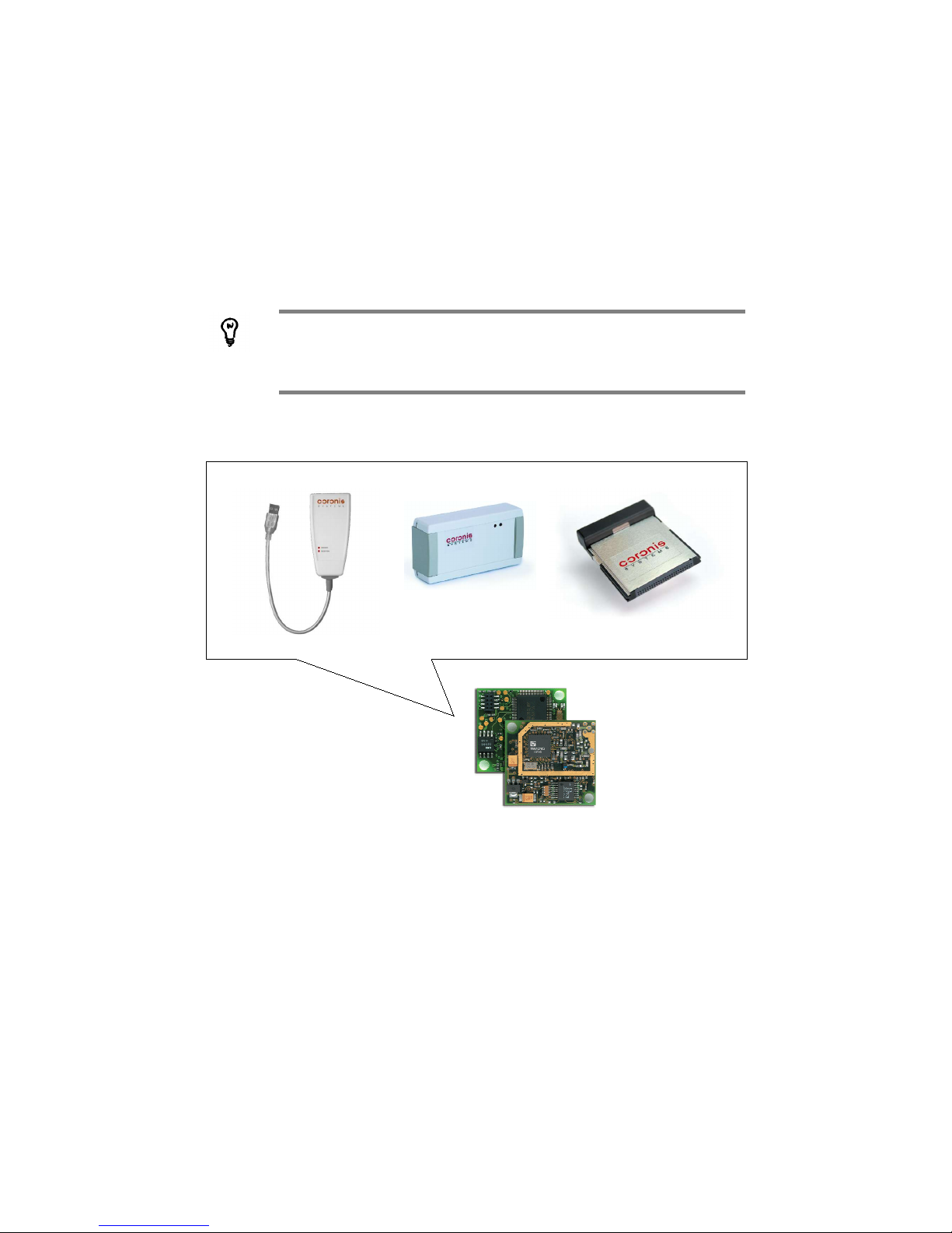
Coronis Systems Wavecard and Waveport products use the same Wavenis
wireless board. Therefore, this document covers both products, as well as
Waveport module with serial, USB, or compact flash connectors. We will
generally refer to Wavecard, except where there are specific differences
between products
Wavecard’s role is to:
• Send data frames wirelessly between host modules
• Notify the host module about received frames
Each Wavecard needs to be connected to a host module in order to exchange data. However, Wavecard can
process some specific frames without being connected to a host. These exchanges are called Service
Exchanges, and are mainly used for installation and maintenance procedures.
CS-SUP-MUTI-WPORTAPP-E04 6
Figure 1 – Waveport USB, serial,
and compact flash products are
all based on Wavecard
Page 7
Wavecard-Waveport User Manual Coronis Systems
1.1 Scope of this document
The purpose of this document is to present:
• A low-level description of the exchange protocol used to drive the Wavecard wireless board
through an asynchronous serial RS232 (±12V) or TTL level (0-3V) interface
• The Wavecard electrical interface
• The Wavecard mechanical interface
1.1.1 Terms
This document provides specifications for using supplied Wavenis DLLs for Windows as well as for writing
your own. This allows you to use Wavecard as a wireless modem that can be integrated into existing
modules or driven by a specific host module with its own micro-controller.
As mentioned above, this document is valid for both Wavecard and Waveport products. The main difference
is that Waveport is a ready-to-use Wavenis network interface for PCs with USB, serial, or compact flash (type
II) connectors.
In this documentation, host refers to the module or subsystem that drives the Wavecard; radio board
indicates Wavecard equipment.
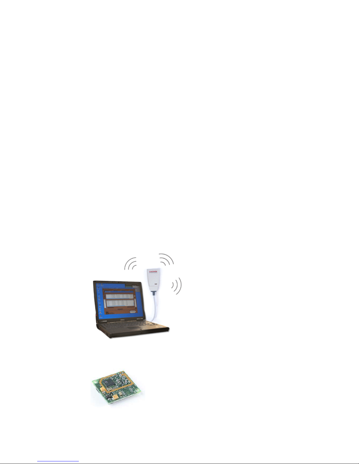
1.1.2 Usage scenarios
Use Waveport to establish Wavenis connections from your PC.
Integrate Wavecard into your own projects or prototypes.
CS-SUP-MUTI-WPORTAPP-E04 7
Page 8
Wavecard-Waveport User Manual Coronis Systems
2. RS232 SERIAL PROTOCOL PRESENTATION
This protocol is dedicated to an asynchronous RS232 or TTL link between the host and the radio board. The
transmission format is:
• 8 data bits
• 1 stop bit
• No parity
• Speed: 9600 baud (please contact us if your application requires other speeds)
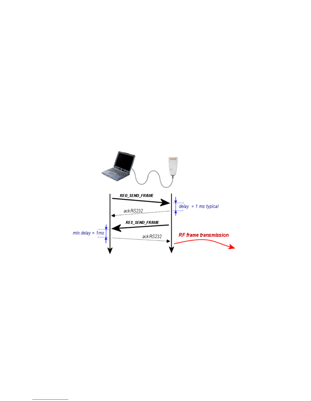
2.1 Basic data exchange
In most cases, the host module initiates data exchange, but either the host or the radio board can do it.
Figure 2 – Overview of data exchange between a Waveport modem and host
2.1.1 Low-level acknowledgement
Serial frames exchanged between a host and radio board are always managed by an acknowledge
mechanism.
In order to take processing time into account on the radio board, a minimum latency time of 1 ms must be
respected between frame reception and transmission of the corresponding acknowledgement.
If the Acknowledge frame is not received by the initiator, it can decide to re-send the frame several times
(retry mechanism). The default setting for this is:
Time-out = 500 ms
retry count = 3
CS-SUP-MUTI-WPORTAPP-E04 8
Page 9
Wavecard-Waveport User Manual Coronis Systems
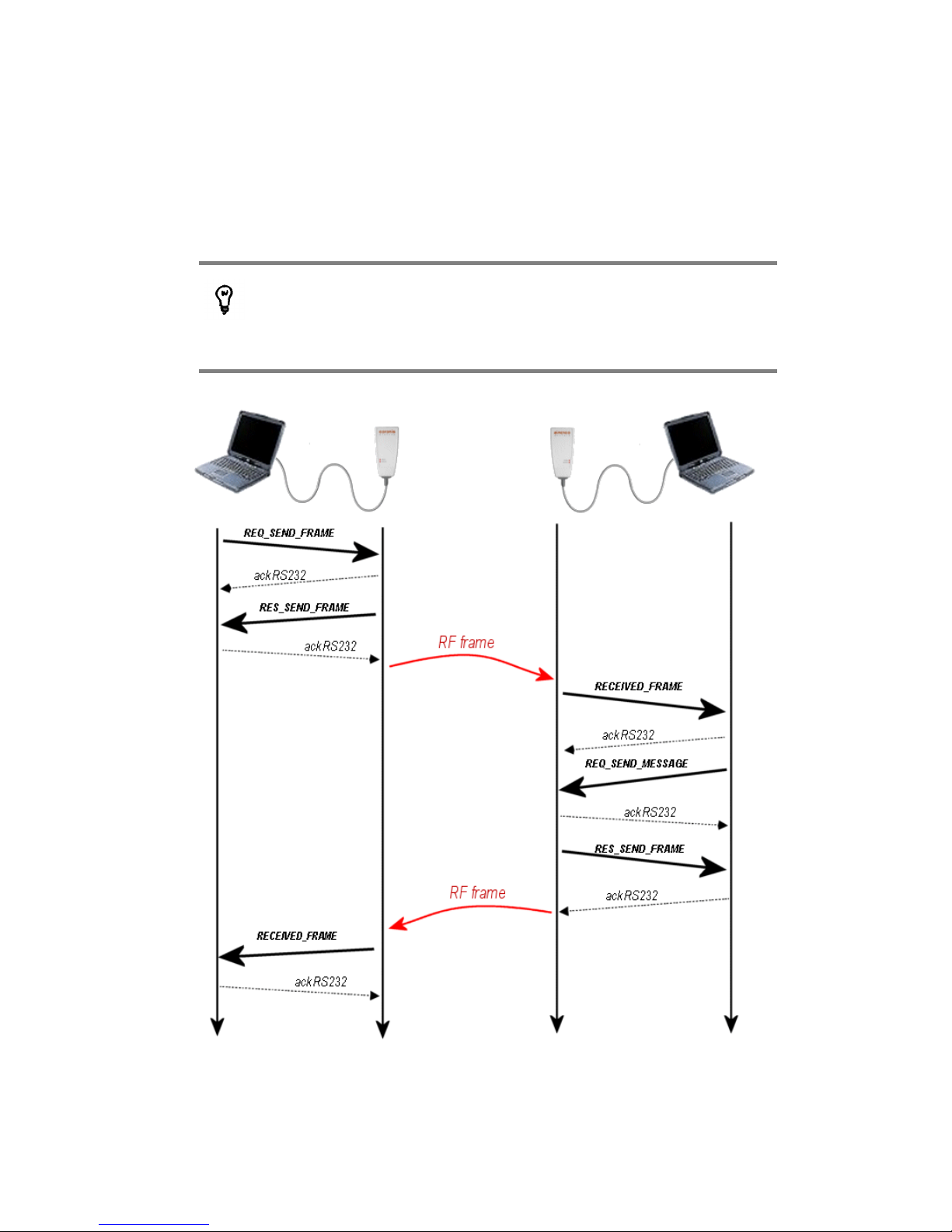
2.1.2 Request / response mechanism
Some exchanges require using a request/response mechanism. In this case, a high-level acknowledgement
(command prefix: RES) is initiated by the RF board following the request frame (command prefix: REQ) sent
by the host.
Request frames are identified by “REQ_XXX_XXX” (i.e.
REQ_SEND_FRAME)
High-level acknowledgement frames are identified by “RES_XXX_XXX”
(i.e. RES_SEND_FRAME).
In this example, the RECEIVED_FRAME frame is the response to the REQ_SEND_FRAME request. Highlevel acknowledgement of the request is identified by the RES_SEND_FRAME frame.
CS-SUP-MUTI-WPORTAPP-E04 9
Page 10

Wavecard-Waveport User Manual Coronis Systems
2.2 Format of exchanged frames
2.2.1 Wake-up and synchronization mechanism
Wavecard normally stays in standby mode to optimize power consumption, waking up either:
• To poll for radio activity periodically
• When a serial frame is received from host equipment
In order to give the radio board time to wake up, a synchronization character is needed before the data in the
serial frame. This character is 0xFF in hexadecimal notation.
To be consistent, the radio board also precedes its frame transmissions with this synchronization character.
2.2.2 Frame description
The standard frame format is as follows:
SYNC STX LENGTH CMD DATA CRC ETX
1 byte 1 byte 1 byte 1 byte 0 - 250 bytes 2 bytes 1 byte
Sync.
character
Start of
transmission
character
Frame
length
Command Data
Control
Redundancy
Check
LSB First
End of
transmission
character
0xFF 0x02 0x03
LENGTH
• Minimum frame size is 6 bytes.
• Maximum frame size is 256 bytes.
• Frame length (byte LENGTH) is computed from its own position
through the included CRC. SYNC, STX, and ETX bytes are not
included in the length.
To ensure the integrity of information transmitted between the host and radio board, a 16-bit CRC code is
computed on overall frame data, not including STX and ETX characters (byte LENGTH is inserted in the
CRC).
The CRC code is computed by dividing the binary frame sequence by the following polynomial:
X16 + X12 + X5 + 1
Sample code for this is shown on the following page.
CS-SUP-MUTI-WPORTAPP-E04 10
Page 11

Wavecard-Waveport User Manual Coronis Systems
2.2.3 Sample CRC code (C language)
This example shows how to compute CRC on a fixed frame length equal to 9.
#include <iostream.h>
#include <stdio.h>
#include <string.h>
void main ( )
{
int Poly = 0x8408;
int lg = 9;
unsigned int Frame [] = { 0x0B, 0x20, 0x43, 0x06, 0x01, 0x00, 0x00, 0x02, 0X01};
unsigned int Crc;
int j, i_bits, carry;
Crc = 0;
for ( j=0 ; j < lg ; j++ )
{
Crc = Crc ^ Frame[j] ;
for ( i_bits=0 ; i_bits < 8 ; i_bits++ )
{
carry = Crc & 1 ;
Crc = Crc / 2 ;
if ( carry )
{
Crc = Crc ^ Poly;
}
}
}
printf ( “CRC = %x “, Crc);
}
Notes:
• The computed CRC is: 41D2 hexadecimal
• The LSB and MSB bytes must then be inverted before storing them in the frame.
CS-SUP-MUTI-WPORTAPP-E04 11
Page 12

Wavecard-Waveport User Manual Coronis Systems
2.3 Command description
This chapter describes the format of serial bus data frames. The distinction between frames is made using
the CMD fields representing the command (or action) to carry out.
The types of available commands can be split into three categories:
• Control type commands
• Application commands
• Service type commands
2.3.1 Control commands
These commands are used for low-level acknowledgement of serial frames.
CMD Name Description Data field format
0x06 ACK
Acknowledgement frame:
Sent by the receiver after receiving a request/response frame
type that was supported and understood.
No data field
0x15 NAK
Non-acknowledgement frame:
Sent by the receiver after receiving a request/response frame
that was not understood.
No data field
0x00 ERROR
Error frame:
Sent by the receiver after receiving a request/response frame
that was understood but not supported.
Byte 1:
0x01: unknown command
2.3.2 Application commands
Application type commands use the request/response mechanism. There are two types of application type
commands: (1) those relating to parameter settings and board configuration, and (2) those related to radio
frame exchanges.
Commands related to parameter settings
• Read or update internal parameters
• Read or select radio operating channel when FHSS is deselected
• Read or select the radio communication mode
• Read or select radio board transmission power
• Activate Wavenis RF ASIC RSSI threshold auto-correction
• Modify serial link baud rate
• Read RSSI level of a remote module
• Reading Wavecard RSSI level following an exchange with a remote module
• Read Wavecard firmware version
• Set Wavecard to test mode
CS-SUP-MUTI-WPORTAPP-E04 12
Page 13

Wavecard-Waveport User Manual Coronis Systems
Commands related to radio frame exchanges
Radio exchanges are composed of several transmission/reception modes. In some cases it is possible to
receive several consecutive radio frames (multi-frame mode which is accessible in reception only).
The following modes allow point-to-point exchange:
Frame exchange mode Wavecard sends a request and waits for a response from remote module.
Following the radio frame sending, the Wavecard radio board stay in radio
reception during a time (fixed by default at 2s, cf. RADIO_USER_TIMEOUT)
in order to receive the response from the addressed equipment. During this
time the serial RS232 link is not managed. This command is particularly
intended to read CORONIS SYSTEMS radio modules used to collect remote
information (temperature, humidity, meters index, ...).
Message mode Wavecard sends a request without waiting for a response from the remote
module.
After sending a frame, the Wavecard radio board goes back to listening on
the serial RS232 link. This command may be used for simple data transfer
between Wavecard modules.
Relay mode When a remote module is beyond a transmitting module's radio range, relay
mode may be used to forward frames via intermediate nodes (repeaters).
The maximum number of repeaters is 3.
The modes below allow selective and non-selective exchange with several remote modules at once:
Polling This mode is used to address requests to a known list of remote modules.
Responses are sent to the host that issued the request when all remote
modules have responded, or after a time-out.
The list of remote modules is configured with a parameter setting command
(see chapter 3).
Broadcast This mode allows a Wavecard to issue a request to all remote modules
within radio range of the transmitter. Broadcast may also be limited to a
selected group of modules.
Multi-frame reception This is a particular case in which multi-frame exchange takes place between
a Wavecard or Waveport module (considered to be the master of the
exchange) and another Wavenis-based telemetry module, such as
Wavetherm, Waveflow, Wavesense, etc.
Note: Wavecard does not currently allow multi-frame mode between two
Wavecard/Waveport modules.
CS-SUP-MUTI-WPORTAPP-E04 13
Page 14

Wavecard-Waveport User Manual Coronis Systems
2.3.3 Service commands
Service commands are used to configure a Wavecard or to read radio parameters independently of the
connected host equipment.
When a Wavecard recognizes a service command, no data is sent to the connected host. These commands
are mainly used to handle:
• Detection of remote RF modules
• Link budgets with respect to remote modules (RSSI level detection)
• Setting parameters via RF
The details of the frame format and its usage are described in chapter 4.
CS-SUP-MUTI-WPORTAPP-E04 14
Page 15

Wavecard-Waveport User Manual Coronis Systems
3. SETTING INTERNAL WAVECARD PARAMETERS
Internal Wavecard parameters can be separated into two categories:
• Control parameters that are carried out by specific types of request/response frames. These
parameters (transmission power level, channel selection, etc...) allow you to change the
communication mode (either serial and/or RF).
• Functional parameters that are carried out by the same frame as those used for writing internal
parameters. These parameters (Wake-up period, group number, etc...) allow you to modify
Wavecard behavior according to the type of radio exchange used.
Commands for setting parameters only apply to a local Wavecard, not
remote ones.
3.1 Configuring functional parameters
Functional parameters are directly related to Wavecard's default operation, and to the types of radio
exchanges used (i.e. functional parameters are initialized according to the intended type of radio exchange).
Default values are set when the unit is first initialized.
Parameter
number
Description Value
Size
(bytes)
0x00
AWAKENING_PERIOD: RF polling period, in
multiples of 100 ms
Period in multiples of 100ms (by default,
0x0A for one second; max. = 10 sec.)
0 = nearly constant reception (every 20ms)
1
0x01
WAKEUP_TYPE: wake-up type used during frame
transmission
0: long wake-up (default setting)
1: short wake-up = 50 ms
1
0x02
WAKEUP_LENGTH: wake-up duration when long
wake-up is set used
This value must be higher than the RF polling period.
Value in multiples of 1 ms, LSB defined first.
Default value: 1100 ms
min. value = 20 ms (0x1400)
max. value = 10 sec. (0x1027)
2
0x03
WAVECARD_POLLING_GROUP: byte containing
the Wavecard polling group.
Byte 1: Polling_Group
Default Polling_Group = 0x00
1
0x04
RADIO_ACKNOWLEDGE: indicates whether radio
frames should acknowledged by the receiver.
0: no acknowledgement
1: with acknowledgement (default value)
1
0x05 RADIO_ADDRESS: radio board address
This value is set a the factory.
Read-only
6
0x06
RELAY_ROUTE _STATUS: Parameter related to
relay route transmission in each relayed frame
received.
0x00: Relay route transmission deactivated
0x01: Relay route transmission activated
By default, relay route transmission is
deactivated
1
0x07
RELAY_ROUTE : Table containing the radio
addresses for successive repeaters used to reach
the destination module.
BYTE 1: number of repeaters in route
Maximum number of repeaters = 3
If BYTE 1 != 0
BYTES 2 to 7: First repeater's radio
address..., etc.
1 to 19
CS-SUP-MUTI-WPORTAPP-E04 15
Page 16

Wavecard-Waveport User Manual Coronis Systems
0x08
POLLING_ROUTE: Table containing the list of
module radio address to be queried.
BYTE 2: number of modules to query
IF BYTE 2 != 0
BYTES 3 to 8: radio address of the first
module..., etc.
1 to 241
0x09
GROUP_NUMBER: Byte containing the group
number of radio modules to address in radio polling
mode.
Group number
Default GROUP_NUMBER = 0x00
1
0x0A
POLLING_TIME: delay between two consecutive
transmissions in polling mode
Value in multiples of 100 ms
Default POLLING_TIME = 0x0A
1
0x0C
RADIO_USER_TIMEOUT: time-out for receiving a
response frame
Value in multiples of 100ms
default value = 0x14 (2 seconds)
1
0x0E
EXCHANGE_STATUS: parameter for activating
error or status frame management.
0: status and error frames deactivated
1: error frame activated
2: status frame activated
3: both status and error frames activated
Default EXCHANGE_STATUS = 0x00.
1
0x10
SWITCH_MODE_STATUS: automatic selection of
Radio communication mode used to address an
equipment depending on radio address
0: automatic selection deactivated
1: automatic selection activated
Default SWITCH_MODE_STATUS = 0x01
1
0x16
WAVECARD_MULTICAST_GROUP: byte
containing the Wavecard multicast group (starting
with version 2.00).
By default, no group selected = 0xFF 1
0x17
BCST_RECEPTION_TIMEOUT: time-out for
receiving CSMA frame following a transmitted
REQ_SEND_BROADCAST command (starting with
firmware version 2.01)
Value in multiples of100 ms.
Default = 0x3C (6 seconds)
1
3.1.1 Format for accessing internal parameters
Wavecard manages internal parameters mainly for RF features. RS232 commands allow you to access
these parameters in read or write mode. Default values are set when the module is first used.
REQ_READ_RADIO_PARAM is used to read parameters, and REQ_WRITE_RADIO_PARAM is used to
write parameters. Each parameter must be accessed individually.
CMD NOM DESCRIPTION
0x40 REQ_WRITE_RADIO_PARAM Request to update radio parameters
0x41 RES_WRITE_RADIO_PARAM Radio board response to radio parameter update
0x50 REQ_READ_RADIO_PARAM Request to read radio parameters
0x51 RES_READ_RADIO_PARAM Radio board response to parameter reading
In command byte coding, response frames reuse the request command
with the LSB bit set to 1.
CS-SUP-MUTI-WPORTAPP-E04 16
Page 17

Wavecard-Waveport User Manual Coronis Systems
The format for data fields for reading or updating radio parameters is given below:
• Request to read radio parameters
REQ_READ_RADIO_PARAM
HEADER CMD DATA CRC ETX
3 bytes 1 byte 1 byte 2 bytes 1 byte
0xFF ; 0x02 ; 0x05 0x50 Number of the parameter to read 0x03
• Radio board response to parameter reading
RES_READ_RADIO_PARA M
HEADER CMD DATA CRC ETX
3 bytes 1 byte 1 byte variable 2 bytes 1 byte
0xFF ; 0x02 ; 0xXX 0x51
Status = 0x00 read ok
Status = 0x01 read error
value
-
0x03
• Request to update radio parameters
REQ_WRITE_RADIO_PARAM
HEADER CMD DATA CRC ETX
3 bytes 1 byte 1 byte variable 2 bytes 1 byte
0xFF ; 0x02 ; 0xXX 0x40
Number of the parameter
to update
Parameter data 0x03
• Radio board response to radio parameter update
RES_WRITE_RADIO_PARAM
HEADER CMD DATA CRC ETX
3 bytes 1 byte 1 byte 2 bytes 1 byte
0xFF ; 0x02 ; 0x05 0x41
STATUS
= 0x00 update OK
= 0x01 update error
0x03
Managing time-outs
Your product may need servicing if you consistently encounter the
following latencies. Please contact technical support for more
information.
REQ_WRITE_RADIO_PARAM 2 seconds
REQ_READ_RADIO_PARAM 2 seconds
CS-SUP-MUTI-WPORTAPP-E04 17
Page 18

Wavecard-Waveport User Manual Coronis Systems
RES_WRITE_RADIO_PARAM
HEADER CMD DATA CRC ETX
3 bytes 1 byte 1 byte 2 bytes 1 byte
0xFF ; 0x02 ; 0x05 0x41
STATUS
= 0x00 update OK
= 0x01 update error
0x03
3.1.2 Example: Configuring repeater table and activating error frames
In this case there is a repeater module (radio address: 0X AA AA AA AA AA AA) between the Wavecard (initiating the
exchange) and the remote module. We must enable error frames in order to determine which remote module caused
the error.
Configure repeater list
• Host request to the Wavecard (REQ_WRITE_RADIO_PARAM)
HEADER
SYNC STX LENGTH
CMD
DATA
Parameter
number
Parameter data
CRC ETX
0xFF 0x02 0x0C 0x40 0x07 0x01 ; 0xAAAAAAAAAAAA 0xXXXX 0x03
• Wavecard response to host (RES_WRITE_RADIO_PARAM)
HEADER
SYNC STX LENGTH
CMD
DATA
Status of the update
CRC ETX
0xFF 0x02 0x05 0x41 0x00 0xXXXX 0x03
Activate error frames
• Host request to Wavecard (REQ_WRITE_RADIO_PARAM)
HEADER
SYNC STX LENGTH
CMD
DATA
Parameter
number
Parameter data
CRC ETX
0xFF 0x02 0x06 0x40 0x0E 0x01 0xXXXX 0x03
• Response from the WaveCard to the host (RES_WRITE_RADIO_PARAM)
HEADER
SYNC STX LENGTH
CMD
DATA
Status of the update
CRC ETX
0xFF 0x02 0x05 0x41 0x00 0xXXXX 0x03
CS-SUP-MUTI-WPORTAPP-E04 18
Page 19

Wavecard-Waveport User Manual Coronis Systems
3.2 Wake-up and synchronization
Wavecard optimizes power consumption by using STANDBY mode, waking up periodically to poll for radio
activity. The wake-up period is defined by the value of the AWAKENING_PERIOD parameter, expressed in
multiples of 100 ms (1 second by default).
3.2.1 Transmitting and receiving frames
When transmitting a frame to a remote module, the transmitter begins an awakening procedure called
WakeUp, which is used to wake receiving modules, which then switch to RF reception mode. A succession of
binary symbols are sent by the radio during this preamble procedure.
There are two types of wake-up procedures:
Long wake-up Used when transmitting a request towards a remote module. You may set
duration parameters (1100 ms by default), which is generally equal to the
wake-up period of the module you are trying to reach, plus 100 ms in order
to avoid transmitting between two reception periods.
Short wake-up Used only when responding to a point-to-point request. Duration is 50ms and
cannot be changed.
NUM DESCRIPTION VALUE
SIZE
(in bytes)
0x00
AWAKENING_PERIOD
RF polling period in multiples of 100 ms
Period in multiples of 100 ms
(by default, 0x0A for one second)
0 = nearly constant reception (every 20 ms)
1
0x01
WAKEUP _TYPE
Type of wake-up used during frame transmission
0: long wake-up (default setting)
1: short wake-up = 50 ms
1
0x02
WAKEUP _LENGTH
Duration of the Wake up when long wake up is set up.
This value must be higher than the RF polling period.
Value in multiples of 1ms, LSB defined first.
Default value : 1100 ms
Min. value = 20 ms (0x1400)
Max. value = 10 sec. (0x1027)
2
When the receiving RF module detects the wake-up procedure, it executes the following operations:
• It starts a time-out to wait for the synchronization word (sync). Duration of the time-out is slightly
longer than its WakeUp period, and cannot be changed.
• It begins a phase of validating the WakeUp preamble (WakeUp detection). This phase
corresponds to the detection of several successive symbols that compose the preamble. If
detection fails, the module returns to stand-by mode. Detection time depends on transmission
speed.
CS-SUP-MUTI-WPORTAPP-E04 19
Page 20
Wavecard-Waveport User Manual Coronis Systems
The periodic wake-up having to occur when waiting of synchronization, are
memorized (in order to preserve the periodicity), but not carried out.
At the end of the the wake-up phase, the transmitter modules sends a synchronization sequence, followed by
the data to be transmitted.
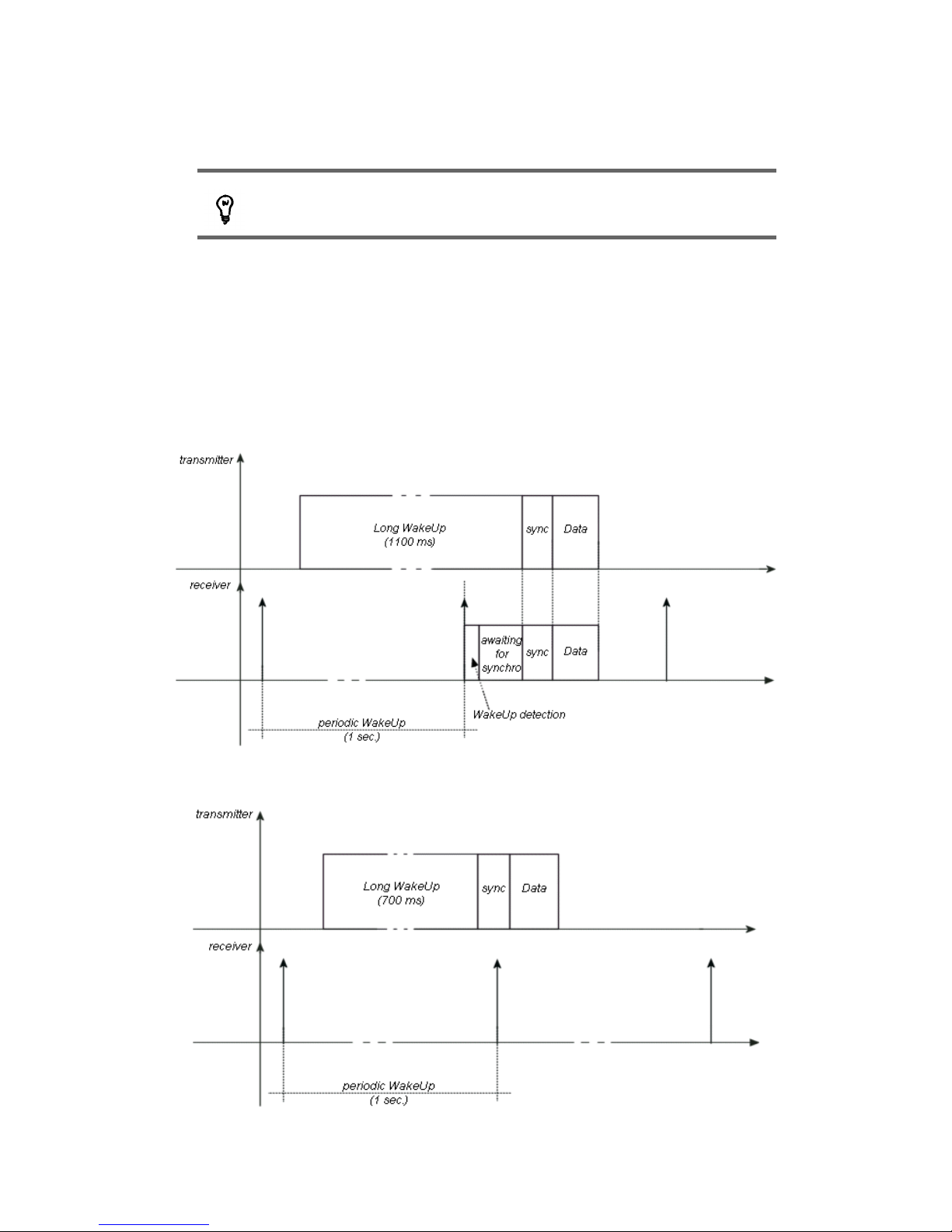
3.2.2 Examples of different wake-up conditions
Typical case (Long WakeUp = receiver WakeUp period + 100 ms):
Case where wake-up is too short (lower than the receiver's WakeUp period):
CS-SUP-MUTI-WPORTAPP-E04 20
Page 21
Wavecard-Waveport User Manual Coronis Systems
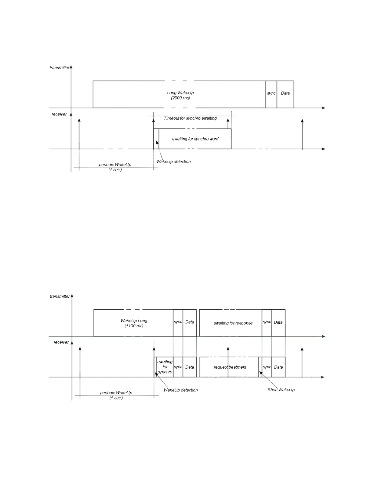
Case where WakeUp is too long (much higher than the receiver's WakeUp period):
3.2.3 Example of point-to-point request / response exchange
When using a point-to-point (request/response) exchange, the request is transmitted in the same manner as
before. However, in this case, the transmitter waits for a response after sending the data. The time-out period
for this can be configured using the RADIO_USER_TIMEOUT parameter (0x0C).
After processing the request, the receiver returns its response by using a specific WakeUp preamble, called
short WakeUp (Long WakeUp is not applicable since the transmitter is already in the receiving phase).
Exchange without radio acknowledgement:
CS-SUP-MUTI-WPORTAPP-E04 21
Page 22

Wavecard-Waveport User Manual Coronis Systems
Exchange with radio acknowledgement
Example of parameter configuration for wake-up management
In this example, the transmitter sends data to the receiver quickly between two relatively long
idle periods:
1) Send a parameter modification command to the receiver to modify its WakeUp period to
0 (nearly constant reception).
2) Set the transmitter's WakeUp_Length parameter to 40 ms.
3) Send the data to the receiver.
4) Send a parameter modification command to the receiver to set its wake-up period to 10 s
(default value).
5) Set the transmitter's WakeUp_Length parameter to 1100 ms (default value).
3.3 Configuring control parameters
Control parameters are used to:
• Modify RF and serial communications
• Retrieve information about the local module and communication quality with a remote module
CS-SUP-MUTI-WPORTAPP-E04 22
Page 23

Wavecard-Waveport User Manual Coronis Systems
3.3.1 Selecting RF communication mode
The following physical layer modes are available:
• 868 MHz single channel, 4800 baud
• 868 MHz single channel, 4800 baud alarm band
• 868 MHz single channel, 9600 baud with channel selection
• 868 MHz frequency hopping, 9600 baud
• 868 MHz frequency hopping, 19200 baud
• 869 MHz, 500mW band (Note: this mode is supported on the Wavecard 25mW radio board, but
transmission power is limited).
You may modify the physical layer mode with read and write requests. The commands for this are:
CMD NAME DESCRIPTION
0x64 REQ_SELECT_PHYCONFIG Request to select RF communication mode
0x65 RES_SELECT_PHYCONFIG Response to communication mode selection request
0x66 REQ_READ_PHYCONFIG Request to read RF communication mode
0x67 RES_READ_PHYCONFIG Response to communication mode read request
In command byte coding, response frames reuse the request command with
the LSB bit set to 1.
Format of physical layer mode read commands
• Request (host to Wavecard)
REQ_READ_PHYCONFIG
HEADER CMD CRC ETX
3 bytes 1 byte 2 bytes 1 byte
0xFF ; 0x02 ; 0x04 0x66 0x03
• Response (Wavecard to host)
RES_READ_PHYCONFIG
HEADER CMD DATA CRC ETX
3 bytes 1 byte variable 2 bytes 1 byte
0xFF ; 0x02 ; 0xXX 0x67
Status = 0x00
Read OK
Transmission mode
2 bytes
Status = 0x01
Read error
-
0x03
CS-SUP-MUTI-WPORTAPP-E04 23
Page 24

Wavecard-Waveport User Manual Coronis Systems
The table below shows available physical layer modes:
Communication mode
Value
433 MHz frequency hopping 9600 baud 0x00A1
868 MHz single channel 4800 baud 0x0012
868 MHz single channel 4800 baud Alarm Band 0x0094
868MHz single channel 9600 baud with channel selection 0x00A2
868 MHz frequency hopping 9600 baud 0x00A3
868 MHz frequency hopping 19200 baud 0x00B3
869MHz 500mW Band 0x00B6
915 MHz frequency hopping 19200 baud 0x00B9
* Wavecard products support 433, 868, or 915 MHz (i.e. not all three on the same card).
Format of selection commands for physical layer mode to use
• Request (host to Wavecard)
REQ_SELECT_PHYCONFIG
HEADER CMD DATA CRC ETX
3 bytes 1 byte 2 bytes 2 bytes 1 byte
0xFF ; 0x02 ; 0x06 0x64 RF transmission mode 0x03
• Response (Wavecard to host)
RES_SELECT_PHYCONFIG
HEADER CMD DATA CRC ETX
3 bytes 1 byte 1 byte 2 bytes 1 byte
0xFF ; 0x02 ; 0x05 0x65
Status
( 0x00 : Update OK ; 0x01 : Update error )
0x03
Automatic selection of communication modes
Each Wavenis module indicates its transmission mode in its radio address. Wavecard uses a parameter in
order to select its transmission mode based on the radio address of a remote module. If the
SWITCH_MODE_STATUS parameter is activated, Wavecard analyzes the remote module's transmission
mode and modifies its own mode accordingly. If the SWITCH_MODE_STATUS parameter is deactivated, the
WaveCard communicates with its default transmission mode.
Parameter
number
Description Value
Size
(in bytes)
0x10
SWITCH_MODE_STATUS : automatic
selection of Radio communication mode used
to address an equipment depending on radio
address (available from firmware v1.00)
0 : automatic selection deactivated
1 : automatic selection activated
By default:
SWITCH_MODE_STATUS = 0x01
1
CS-SUP-MUTI-WPORTAPP-E04 24
Page 25

Wavecard-Waveport User Manual Coronis Systems
3.3.2 Selecting radio channel when FHSS is deselected
You may select the Wavecard radio channel using these commands:
CMD Nam e Description
0x60 REQ_SELECT_CHANNEL
Request to select operating radio channel when FHSS is
deselected
0x61 RES_SELECT_CHANNEL Response to channel selection request
0x62 REQ_READ_CHANNEL
Request to read the operating radio channel when FHSS is
deselected
0x63 RES_READ_CHANNEL Response to the read channel request
These commands are used only when the radio communication mode is monofrequency with channel selection.
Format of read commands for channel used
• Request (host to Wavecard)
REQ_READ_CHANNEL
HEADER CMD CRC ETX
3 bytes 1 byte 2 bytes 1 byte
0xFF ; 0x02 ; 0x04 0x62 0x03
• Response (Wavecard to host)
RES_READ_CHANNEL
HEADER CMD DATA CRC ETX
3 bytes 1 byte variable 2 bytes 1 byte
0xFF ; 0x02 ; 0xXX 0x63
Status = 0x00
read OK
Channel number
1 byte
Status = 0x01
Read error
-
0x03
CS-SUP-MUTI-WPORTAPP-E04 25
Page 26

Wavecard-Waveport User Manual Coronis Systems
Format of write commands for channel to use
• Request (host to Wavecard)
REQ_SELECT_CHANNEL
HEADER CMD DATA CRC ETX
3 bytes 1 byte 1 byte 2 bytes 1 byte
0xFF ; 0x02 ; 0x05 0x60 Channel number (0 - 21) 0x03
• Response (Wavecard to host)
RES_SELECT_CHANNEL
HEADER CMD DATA CRC ETX
3 bytes 1 byte 1 byte 2 bytes 1 byte
0xFF ; 0x02 ; 0x05 0x61
Status
( 0x00 : update OK ; 0x01 : update error )
0x03
3.3.3 Selecting radio board transmission power
This function is only available on the Wavecard 25 mW board
You may adjust the transmission power of the Wavecard radio board as indicated in the table below. By
default the level is set to 14 dBm.
Parameter value 0x0A 0x09 0x08 0x07 0x06 0x05 0x04 0x03 0x02 0x01 0x00
Power level (dBm) 14 12 11 9.7 7.9 5.5 3.3 2.1 -0.3 -4 -16
The output power values given here are approximate ((±2dBm). Wavecard radio boards are optimized for
25mW radiated RF Power.
The commands for modifying and reading the power level are:
CMD Name Description
0x44 REQ_CHANGE_TX_POWER Request to update radio board transmission power
0x45 RES_CHANGE_TX_POWER Radio board response to transmission power update
0x54 REQ_READ_TX_POWER Request to read radio board transmission power
0x55 RES_READ_TX_POWER Radio board response to transmission power read
In command byte coding, response frames reuse the request command with the LSB bit set to 1.
CS-SUP-MUTI-WPORTAPP-E04 26
Page 27

Wavecard-Waveport User Manual Coronis Systems
Format of commands for selecting transmission power
• Request (host to Wavecard)
REQ_CHANGE_TX_P OWER
HEADER CMD DATA CRC ETX
3 bytes 1 byte 1 byte 2 bytes 1 byte
0xFF ; 0x02 ; 0x05 0x44 Parameter value (0x0A, by default) 0x03
• Response (Wavecard to host)
RES_CHANGE_TX_POWER
HEADER CMD DATA CRC ETX
3 bytes 1 byte 1 byte 2 bytes 1 byte
0xFF ; 0x02 ; 0x05 0x45
Status
0x00 : Update OK
0x01 : Update error
0x03
Format of commands for reading transmission power
• Request (host to Wavecard)
REQ_READ_TX_POWER
HEADER CMD CRC ETX
3 bytes 1 byte 2 bytes 1 byte
0xFF ; 0x02 ; 0x04 0x54 0x03
• Response (Wavecard to host)
RES_READ_TX_POWER
HEADER CMD DATA CRC ETX
3 bytes 1 byte 1 byte 2 bytes 1 byte
0xFF ;
0x02 ;
0x05
0x55 Parameter value 0x03
When the Wavecard is reset, its power level is reset to the default value of 14 dBm
(0x0A).
CS-SUP-MUTI-WPORTAPP-E04 27
Page 28

Wavecard-Waveport User Manual Coronis Systems
3.3.4 Activating RSSI threshold auto-correction
RSSI threshold auto-correction is a feature that enables Wavecard to adjust its reception threshold according
to ambient noise. This feature is consistent with other Wavenis power-saving techniques, and is implemented
by battery-powered Wavecard modules at reset. By default RSSI threshold auto-correction is activated.
Commands for modifying and reading the auto-correction state are:
CMD NAME DESCRIPTION
0x46 REQ_WRITE_AUTOCORR_STATE Request to update threshold auto-correction state
0x47 RES_WRITE_AUTOCORR_STATE
Radio board response threshold auto-correction state
update
0x5A REQ_READ_AUTOCORR_STATE Request to read threshold auto-correction state
0x5B RES_READ_AUTOCORR_STATE
Radio board response to threshold auto-correction state
read
Note: In command byte coding, response frames reuse the request command with the LSB bit set to 1.
Format of modification commands for RSSI threshold auto-correction state
• Request (host to Wavecard)
REQ_WRITE_AUTOCORR_STATE
HEADER CMD DATA CRC ETX
3 bytes 1 byte 1 byte 2 bytes 1 byte
0xFF ; 0x02 ; 0x05 0x46
RSSI Threshold auto-correction
0x00: Activated (default value)
0x01: Deactivated
0x03
• Response (Wavecard to host)
RES_WRITE_AUTOCORR_STATE
HEADER CMD DATA CRC ETX
3 bytes 1 byte 1 byte 2 bytes 1 byte
0xFF ; 0x02 ; 0x05 0x47
Status
0x00: Update OK
0x01: Update error
0x03
Format of commands for reading RSSI threshold auto-correction state
• Request (host to Wavecard)
REQ_READ_AUTOCORR_STATE
HEADER CMD CRC ETX
3 bytes 1 byte 2 bytes 1 byte
0xFF ; 0x02 ; 0x04 0x5A 0x03
CS-SUP-MUTI-WPORTAPP-E04 28
Page 29

Wavecard-Waveport User Manual Coronis Systems
• Response (Wavecard to host)
RES_READ_AUTOCORR_STATE
HEADER CMD DATA CRC ETX
3 bytes 1 byte 1 byte 1 byte 2 bytes 1 byte
0xFF ; 0x02 ; 0x06 0x5B
Status
0x00: Reading OK
0x01: Reading error
Auto-correction state
0x00 : activated
0x01 : deactivated
0x03
This parameter returns to its default value after a reset, or after the
Wavecard is switched off
3.3.5 Selecting the serial baud rate
You may change the baud rate of the serial link between the Wavecard and its host. When changes are
made, the baud rate is updated after the current exchange is finished (i.e. the response for the baud rate
change is issued at the same baud rate as the request).
By default, the serial link baud rate is 9600 baud (value = 0x00).
Parameter value 0x00 0x01 0x02 0x03 0x04
Baud rate 9,600 baud 19,200 baud 38,400 baud 57,600 baud 115,200
baud
Commands for changing the baud rate are:
CMD NAME DESCRIPTION
0x42
REQ_CHANGE_UART_
BDRATE
Request to update serial link baud rate
0x43
RES_CHANGE_UART_
BDRATE
Radio board response to the serial link baud rate update. Baud rate is
updated once the exchange has ended.
In command byte coding, response frames reuse the request command with the LSB bit set to 1.
Format of baud rate selection commands
• Request (host to Wavecard)
REQ_CHANGE_UART_BDRATE
HEADER CMD DATA CRC ETX
3 bytes 1 byte 1 byte 2 bytes 1 byte
0xFF ; 0x02 ;
0x05
0x42 Parameter value 0x03
CS-SUP-MUTI-WPORTAPP-E04 29
Page 30

Wavecard-Waveport User Manual Coronis Systems
• Response (WaveCard to host)
RES_CHANGE_UART_BDRATE
HEADER CMD DATA CRC ETX
3 bytes 1 byte 1 byte 2 bytes 1 byte
0xFF ; 0x02 ;
0x05
0x43
Status
0x00 : Update OK
0x01 : Update error
0x03
3.3.6 Reading Wavecard firmware version
Commands for reading the Wavecard firmware version are:
CMD NAME DESCRIPTION
0xA0 REQ_FIRMWARE_VERSION Request to read radio board firmware version.
0xA1 RES_FIRMWARE_VERSION Radio board response to firmware version reading.
In command byte coding, response frames reuse the request command with the LSB bit set to 1.
Wavecard can be considered to be in an error state if more than two
seconds elapses following a read request.
Command format
• Request (host to Wavecard)
REQ_FIRMWARE_VERSION
HEADER CMD CRC ETX
3 bytes 1 byte 2 bytes 1 byte
0xFF ; 0x02 ;
0x04
0xA0 0x03
• Response (WaveCard to host)
RES_FIRMWARE_VERSION
HEADER CMD DATA CRC ETX
3 bytes 1 byte 1 byte 2 bytes 2 bytes 2 bytes 1 byte
0xFF ; 0x02 ;
0x09
0xA1
'V' character in
ASCII
0x56
Transmission mode
(default = 0x00A3)
Firmware version
0x03
CS-SUP-MUTI-WPORTAPP-E04 30
Page 31

Wavecard-Waveport User Manual Coronis Systems
The table below shows available physical layer modes:
Physical layer Value
433 MHz frequency hopping 9600 baud 0x00A1
868 MHz single channel 4800 baud 0x0012
868 MHz single channel 4800 baud Alarm Band 0x0094
868MHz single channel 9600 baud with channel selection 0x00A2
868 MHz frequency hopping 9600 baud 0x00A3
868 MHz frequency hopping 19200 baud 0x00B3
869MHz 500mW Band 0x00B6
915 MHz frequency hopping 19200 baud 0x00B9
* Wavecard products support 433, 868, or 915 MHz (...not all three on the same card).
3.3.7 Reading RSSI
The Received Signal Strength Indicator level (RSSI) represents the Quality Of Service (QOS) level for a given
Wavecard module. This value can be used to verify signal quality in a given mesh network. You may
measure RSSI on local or remote modules. Here are two examples of RSSI measurement:
Example 1: Point-to-point mode
REQ_READ_REMOTE_RSSI: request RSSI level of signal 1.
(i.e. the RSSI level of signal 1 as received by the remote
module)
REQ_READ_LOCAL_RSSI : request the RSSI level of the
signal 2. (i.e. the RSSI level on signal 2 reception by the local
equipment)
Example 2: Request to read RSSI level on a remote module in relay mode
REQ_READ_REMOTE_RSSI: request RSSI of signal 1.
To obtain the RSSI level between repeaters, it is
necessary to issue the REQ_READ_REMOTE_RSSI
request on each repeater.
CS-SUP-MUTI-WPORTAPP-E04 31
LOCAL
DISTANT
2
1
LOCAL
DISTANT
1
Page 32

Wavecard-Waveport User Manual Coronis Systems
Commands
CMD NAME DESCRIPTION
0x68 REQ_READ_REMOTE_RSSI Request to read RSSI level from remote module
0x69 RES_READ_REMOTE_RSSI Remote module response to RSSI level request
0x6A REQ_READ_LOCAL_RSSI
Request to read the Wavecard RSSI level by frame exchange with a
remote module.
0x6B RES_READ_LOCAL_RSSI Response to local RSSI level request
In command byte coding, response frames reuse the request command with the LSB bit set to 1.
3.3.8 RSSI command format
Request to read RSSI level of a remote module
This measurement gives the remote module's RSSI level.
• Request
REQ_READ_REMOTE_RSSI
HEADER CMD DATA CRC ETX
3 bytes 1 byte 6 bytes 2 bytes 1 byte
0xFF ; 0x02 ;
0x0A
0x68 Remote module radio address 0x03
• Response
RES_READ_REMOTE_RSSI
HEADER CMD DATA CRC ETX
3 bytes 1 byte 1 byte 2 bytes 1 byte
0xFF ; 0x02 ;
0x05
0x69
Value of RSSI level upon frame reception from
Wavecard
0x03
Request to read local module's RSSI level
This measurement gives the RSSI level of the local Wavecard by exchanging a frame with a remote module.
• Request
REQ_READ_LOCAL_RSSI
HEADER CMD DATA CRC ETX
3 bytes 1 byte 6 bytes 2 bytes 1 byte
0xFF ; 0x02 ;
0x0A
0x6A Radio address of the remote module 0x03
CS-SUP-MUTI-WPORTAPP-E04 32
Page 33

Wavecard-Waveport User Manual Coronis Systems
• Response
RES_READ_LOCAL_RSSI
HEADER CMD DATA CRC ETX
3 bytes 1 byte 1 byte 2 bytes 1 byte
0xFF ; 0x02 ;
0x05
0x6B
Value of RSSI level of the local Wavecard
upon receiving the frame sent by a remote module
0x03
Min. RSSI level: 0x00 0%
Max. RSSI level: 0x2F 100%
A reading of 92 - 95% is considered as a saturated signal.
3.3.9 TEST Mode
This mode is used for testing Wavecard installation and for identifying anomalies.
• Command
CMD NAME DESCRIPTION
0xB0 MODE_TEST Set WaveCard into test mode
• Command format
MODE_TEST
HEADER CMD DATA CRC ETX
3 bytes 1 byte 1 byte 2 bytes 1 byte
0xFF ; 0x02 ; 0x05 0xB0 Test mode value 0x03
In which:
Test Mode Value Description
0x00 Continuous reception
0x01 Continuous transmission without modulation
0x02 Continuous transmission with modulation
0x03 Stand-by mode
You must reset the Wavecard in order to exit the stand-by test mode, as the
serial port is also in stand-by mode. To exit the other test modes, send a
serial Wavenis frame with 0x00 in the data field, or reset the WaveCard.
CS-SUP-MUTI-WPORTAPP-E04 33
Page 34

Wavecard-Waveport User Manual Coronis Systems
4. SERVICE COMMANDS
Services commands are used to configure Wavecard modules or to read radio parameters independently of
the connected host equipment. No data is sent to the connected host when a Wavecard recognizes a service
command.
These commands are mainly used to handle:
• Detecting remote RF modules
• Link budgets with remote modules (RSSI levels)
• Setting parameters via RF
4.1 Command description and formats
CMD NAME DESCRIPTION
0x80 REQ_SEND_SERVICE Request to send a service frame (and wait for response)
0x81 RES_SEND_SERVICE REQ_SEND_SERVICE response
0x82 SERVICE_RESPONSE Frame received following REQ_SEND_SERVICE transmission
• Service request
REQ_SEND_SERVICE
HEADER CMD DATA CRC ETX
3 bytes 1 byte 6 bytes 1 byte variable 2 bytes 1 byte
0xFF ; 0x02 ;
0xXX
0x80
Radio address of
remote radio module
Service request
type
Parameter(s) related to
request type
0x03
• Service request acknowledgement
RES_SEND_SERVICE
HEADER CMD DATA CRC ETX
3 bytes 1 byte 1 byte 2 bytes 1 byte
0xFF ; 0x02 ;
0x05
0x81
Status
0x00: Frame transmission OK
0x01: Frame transmission error
0x03
• Service request response
SERVICE_RESPONSE
HEADER CMD DATA CRC ETX
3 bytes 1 byte 6 bytes 1 byte variable 2 bytes 1 byte
0xFF ; 0x02 ;
0xXX
0x82
Radio address of
remote radio module
Service
response type
Parameter(s) related to
response type
0x03
CS-SUP-MUTI-WPORTAPP-E04 34
Page 35

Wavecard-Waveport User Manual Coronis Systems
4.2 Request types
The transmitting module sends a service command that includes a request type. Each request type has an
associated response type which is included in the SERVICE_RESPONSE command.
In command byte coding, response frames reuse the request command with the LSB bit set to 1.
• Request type
REQUEST TYPE
NAME VALUE
DESCRIPTION PARAMETER(S)
GET_TYPE 0x20
Command used to
read equipment type
and RSSI level from
remote equipment.
n/a
GET_FW_VER
SION
0x28
Command used to
read firmware version
in remote module.
n/a
• Response type
RESPONSE TYPE
NAME VALUE
DESCRIPTION PARAMETER(S)
RESP_GET_TYPE 0xA0
Response to GET_TYPE
command.
Byte 1: module type
Byte 2: RSSI level
Byte 3: Wake-up period
Byte 4: module type
RESP_GET_FW_VE
RSION
0xA8
Response to
GET_FW_VERSION command.
Byte 1: 'V' in ASCII code (0x56)
Byte 2: Default Radio Protocol (MSB byte)
Byte 3: Default Radio Protocol (LSB byte)
Byte 4: Firmware version (MSB byte)
Byte 5: Firmware version (LSB byte)
CS-SUP-MUTI-WPORTAPP-E04 35
Page 36

Wavecard-Waveport User Manual Coronis Systems
4.3 Detecting presence of Wavecard (Wavenis) modules
It may be useful to check the presence and link budget of a remote module before pursuing data exchange
operations. The Get_Type Command is sent like a service command, allowing a remote Wavecard to
process a response independently of its host equipment. Here is a description of the data frame:
• Service request
REQ_SEND_SERVICE
HEADER CMD DATA CRC ETX
3 bytes 1 byte 6 bytes 1 byte 2 bytes 1 byte
0xFF ; 0x02 ; 0x0B 0x80 Radio address of remote module
0x20
GET_TYPE
0x03
• Service request response
SERVICE_RESPONSE
HEADER CMD DATA CRC ETX
3 bytes 1 byte 6 bytes 1 byte 4 bytes 2 bytes 1 byte
0xFF ; 0x02 ; 0x0F 0x82
Radio address
of remote radio
module
0xA0
Parameters:
1st byte: Type corresponding to
Wavecard radio board = 0x12
2nd byte: RSSI level
3rd byte: Remote Wavecard
wake-up period (in seconds)
4th byte: module type connecting
to Wavecard ( default = 0x12)
0x03
CS-SUP-MUTI-WPORTAPP-E04 36
Page 37

Wavecard-Waveport User Manual Coronis Systems
5. COMMUNICATION MODES
This chapter covers:
• The methods for using Wavecard's four communication modes
• Command format
• Corresponding parameters
5.1 Frame exchange mode
This type of radio exchange allows you to send a request and then wait for a response from remote modules.
Following transmission of a radio frame, the Wavecard radio stays in
reception mode for a period specified by the parameter
RADIO_USER_TIMEOUT. This allows the unit to receive a response from
the remote module.
The RS232 serial connection is not managed during this phase. This
command is generally intended for reading Wavenis-based telemetry
modules (temperature measurement, humidity, liquid flow, tank levels, digital
state management).
5.1.1 Configuring parameters
Frame exchange parameters are accessible REQ_READ_RADIO_PARAM and
REQ_WRITE_RADIO_PARAM. Parameter details are provided in Appendix III of this guide.
NUM DESCRIPTION VALUE
SIZE
(in
bytes)
0x04
RADIO_ACKNOWLEDGE
Indicates whether or not radio frames
should be acknowledged by receiver.
0: no acknowledgement
1: with acknowledgement (default value)
1
0x06
RELAY_ROUTE_STATUS
Parameter related to relay route
transmission in each relayed frame
received.
0x00: Relay route transmission deactivated
0x01: Relay route transmission activated
By default, relay route transmission is
deactivated.
1
0x07
RELAY_ROUTE
Table containing radio addresses of
successive repeaters used to reach the end
module.
BYTE 1: number of repeaters in route.
Maximum number of repeaters = 3
If BYTE 1 != 0
BYTES 2 to 7: Radio address of first repeater …,
etc.
1 to 19
0x0C
RADIO_USER_TIMEOUT
Specifies time-out for receiving response
frames
Value in multiples of 100 ms
Default value = 0x14 (2 seconds)
1
CS-SUP-MUTI-WPORTAPP-E04 37
Page 38

Wavecard-Waveport User Manual Coronis Systems
0x0E
EXCHANGE_S TATUS
Parameter for activating or deactivating
error or status frame management.
0: both status and error frames deactivated
1: error frame activated
2: status frame activated
3: both status and error frames activated
By default, RECEPT_ERROR_STATUS = 0x00
1
5.1.2 Commands and formats
CMD NAME DE SCRIPTION
0x20 REQ_SEND_FRAME Request to send a radio frame and wait for radio response.
0x21 RES_SEND_FRAME
Radio board response to frame transmission (response to requests 0x20,
0x22, 0x24, 0x26, 0x28, 0x2A)
0x30 RECEIVED_FRAME Frame received by radio board.
0x31 RECEPTION_ERROR
Frame indicating error type detected at the end of the last exchange in
point-to-point or relay mode.
0x35 RECEIVED_FRAME_RELAYED
Relay frame received by the radio board. Reception of this command is
possible only if the RELAY_ROUTE_STATUS (0x06) parameter is set.
Here is a description of data frames:
• Request in frame exchange mode
REQ_SEND_FRAME
HEADER CMD DATA CRC ETX
3 bytes 1 byte 6 bytes variable 2 bytes 1 byte
0xFF ; 0x02 ;
0xXX
0x20
Radio address of
target module
n bytes of data to transmit
Maximum size ( N bytes) is defined below
0x03
• Request acknowledgement
RES_SEND_FRAME
HEADER CMD DATA CRC ETX
3 bytes 1 byte 1 byte 2 bytes 1 byte
0xFF ; 0x02 ;
0x05
0x21
Status
0x00: Transmission OK
0x01: Transmission error
0x03
• Request response
RECEIVED_FRAME
HEADER CMD DATA CRC ETX
3 bytes 1 byte 6 bytes variable 2 bytes 1 byte
0xFF ; 0x02 ;
0xXX
0x30
Radio address of
transmitter
data from received frame
Maximum size ( N bytes) is defined below
0x03
CS-SUP-MUTI-WPORTAPP-E04 38
Page 39

Wavecard-Waveport User Manual Coronis Systems
Defining maximum size
• Point to Point mode Max = 152 bytes of data
• Relay mode Max = 152 – (2 + 6 x Number of repeaters)
=> 1 repeater: 144 bytes of data
=> 2 repeaters: 138 bytes of data
=> 3 repeaters: 132 bytes of data
5.1.3 Using relay mode
Relay mode is only available for point-to-point exchanges (frame exchange or message types).
Frame transmission
To send a request to a remote module using relay mode, you must configure a repeater list with
RELAY_ROUTE. When you send a request such as REQ_SEND_FRAME (or REQ_SEND_MESSAGE) to
the receiver's address, the radio frame is relayed automatically through the modules configured by
RELAY_ROUTE.
After sending a request to a recipient, the repeater list (RELAY_ROUTE) is
automatically re-initialized. You must therefore reconfigure it in order to send
another request in relay mode.
Here is an example of sending a REQ_SEND_FRAME request in relay mode:
When REQ_SEND_FRAME is used, the return routing of the response from the remote module is not
automatic; it must be configured by the application running on the remote module.
Generally speaking, if a frame is received in a remote
module and transferred to its host, the list of the relay
addresses for the return trip will need to be configured by
the application.
If the frame was not passed on to the receiver's host, then
the response automatically uses the relay information
contained in the received frame. This is the case with
requests such as REQ_READ_REMOTE_RSSI and
GET_TYPE.
Frame reception
Starting with firmware version v2.00 (v4.00 for 500mW modules), the relay route may be passed from a
received frame to the receiving module's host. To ensure compatibility with previous versions, this
functionality is activated or deactivated by RELAY_ROUTE_STATUS (0x06) parameter on the receiving
module. Depending on the value of this parameter, the host will receive one of the following frames:
RELAY_ROUTE_STATUS value
Type of frame transm itted to host when receiving
a frame in relay mode
0x00: deactivated RECEIVED_FRAME (CMD = 0x30)
0x01: activated RECEIVED_FRAME_RELAYED (CMD = 0x35)
CS-SUP-MUTI-WPORTAPP-E04 39
LOCAL
DISTANT
Page 40

Wavecard-Waveport User Manual Coronis Systems
Here is the format of these frame types:
• Response received by host (RELAY_ROUTE_STATUS deactivated)
RECEIVED_FRAME
HEADER CMD DATA CRC ETX
3 bytes 1 byte 6 bytes variable 2 bytes 1 byte
0xFF ; 0x02 ;
0xXX
0x30
Radio address of
transmitting module
Data from received frame
Maximum size (N bytes) is defined below
0x03
• Response received by host (RELAY_ROUTE_STATUS activated)
RECEIVED_FRAME_RELAYED
HEADER CMD DATA CRC ETX
3 bytes 1 byte 6 bytes 1 byte variable variable 2 bytes 1 byte
0xFF ; 0x02 ;
0xXX
0x35
Radio
address of
transmitting
module
Number of
repeaters
used
Radio
addresses of
repeaters
Data from received frame
Maximum size (N bytes) is
defined below
0x03
The field containing the radio addresses of the repeaters can be 6, 12, or 18 bytes, depending on the number
of repeaters used.
Defining maximum size
• Point to Point mode Max = 152 bytes of data
• Relay mode Max = 152 – (2 + 6 x Number of repeaters)
=> 1 repeater: 144 bytes of data
=> 2 repeaters: 138 bytes of data
=> 3 repeaters: 132 bytes of data
RECEPTION_ERROR frame format
With this command, the local Wavecard informs its host that a problem occurred during the exchange. This
command is forwarded between the Wavecard and its host using the serial link, and therefore does not
require a recipient's address.
Error messages are activated only if the EXCHANGE_STATUS parameter
is set to 0x01 or 0x03.
In the latter case, status messages are also activated but are not used in
this mode, but only when messages are sent without waiting for an answer
(MESSAGE and BROADCAST modes).
CS-SUP-MUTI-WPORTAPP-E04 40
Page 41

Wavecard-Waveport User Manual Coronis Systems
• In point-to-point mode
RECEPTION_ERROR
HEADER CMD DATA CRC ETX
3 bytes 1 byte 1 byte 1 byte 2 bytes 1 byte
0xFF ; 0x02 ;
0x06
0x31
EXCHANGE_MODE :
= 0x01: point-to-point
mode
ERROR_TYPE :
= 0x01: RF acknowledgement not received
from remote module (useful if
acknowledgement mechanism is set)
= 0x02: RF response not received from
remote module
0x03
• In relay mode
RECEPTION_ERROR
HEADER CMD DATA CRC ETX
3 bytes 1 byte 1 byte 1 byte 1 byte 2 bytes 1 byte
0xFF ;
0x02 ;
0x06
0x31
EXCHANGE_MOD
E :
= 0x02: relay mode
0x02
Default
value for
relay
mode
RELAY_COUNTER :
= 0x03 No response from third
repeater
= 0x02 No response from second
repeater
= 0x01 No response from the first
repeater
= 0x00 No response from end-point
module.
0x03
In both cases, the procedure for sending an error frame depends on the RADIO_ACKNOWLEDGE
parameter:
• If RADIO_ACKNOWLEDGE is active, and the transmitter does not receive acknowledgement, the
request is re-sent three times before sending an error frame.
• If RADIO_ACKNOWLEDGE is inactive, then the error frame is sent after the time-out specified by
RADIO_USER_TIMEOUT.
5.1.4 Managing time-outs
When sending a request and waiting for a response (frame exchange), the time-out period for the response
frame is given by parameter RADIO_USER_TIMEOUT. By default the value is 2 seconds.
The beginning of the time-out period depends on the RADIO_ACKNOWLEDGE parameter:
• If RADIO_ACKNOWLEDGE is active, counting begins upon reception of the request
acknowledgement
• If RADIO_ACKNOWLEDGE is inactive, time-out counting begins directly after the request is sent
CS-SUP-MUTI-WPORTAPP-E04 41
Page 42

Wavecard-Waveport User Manual Coronis Systems
Point-to-Point exchange:
CS-SUP-MUTI-WPORTAPP-E04 42
Delta 1: RADIO_USER_TIMEOUT, with RADIO_ACKNOWLEDGE disabled.
Delta 2: RADIO_USER_TIMEOUT, with RADIO_ACKNOWLEDGE enabled.
Delta 1 = Delta 2 = RADIO_USER_TIMEOUT
Page 43

Wavecard-Waveport User Manual Coronis Systems
Relay mode diagram:
When relay mode is used, the time-out (with respect to the transmitter) is not the same as with point-to-point
mode because of the additional time it takes to pass through intermediate nodes. The time-out specified by
RADIO_USER_TIMEOUT is still applied, but it does not take relays into account. The time-out value will be
applied by the last relay before the end-point receiver (R2 Delta = Radio_User_Timeout).
The value of RADIO_USER_TIMEOUT applied by the last repeater is
configured in the transmitter, not in the repeater itself.
In relay mode, repeaters use the RADIO_USER_TIMEOUT value
encapsulated in the transmitter's frame. Repeaters only uses its own
RADIO_USER_TIMEOUT setting when transmitting, not repeating.
In the above diagram, the value of RADIO_USER_TIMEOUT (set by the transmitter) corresponds to time
Delta R2 applied by Relay 2.
Delta 1 and Delta R1 are evaluated by the corresponding radio module, depending on the number of relays
(repeaters), the type of wake-up, duration, and the values of RADIO_USER_TIMEOUT and
RADIO_ACKNOWLEDGE.
CS-SUP-MUTI-WPORTAPP-E04 43
Page 44

Wavecard-Waveport User Manual Coronis Systems
5.2 Message mode
This type of radio exchange allows you to send requests without waiting for remote modules to respond. After
sending a frame the Wavecard board listens on its RS232 serial link. Commands in message mode are
mostly used for simple data transfer between several Wavecard modules.
5.2.1 Configuring message mode parameters
Parameters are accessible using commands REQ_READ_RADIO_PARAM and
REQ_WRITE_RADIO_PARAM (parameter details are provided in Appendix III).
NUM DESCRIPTION VALUE
SIZE
(in
bytes)
0x04
RADIO_ACKNOWLEDGE: indicates
whether or not radio frames should be
acknowledged by receiver.
0: no acknowledgement
1: with acknowledgement (default value)
1
0x06
RELAY_ROUTE _STATUS: Parameter
related to relay route transmission in each
relayed frame received.
0x00: Relay route transmission deactivated
0x01: Relay route transmission activated
By default, relay route transmission is
deactivated.
1
0x07
RELAY_ROUTE : Table containing radio
addresses of successive repeaters used to
reach the end module.
BYTE 1: number of repeaters in route.
Maximum number of repeaters = 3
If BYTE 1 != 0
BYTES 2 to 7: Radio address of first repeater …,
etc.
1 to 19
0x0E
EXCHANGE_STATUS: parameter for
activating or deactivating error or status
frame management.
0: both status and error frames deactivated
1: error frame activated
2: status frame activated
3: both status and error frames activated
By default, RECEPT_ERROR_STATUS = 0x00
1
5.2.2 Commands and formats
CMD NAME DESCRIPTION
0x22 REQ_SEND_MESSAGE Request to send a radio frame and wait for radio response.
0X21 RES_SEND_FRAME
Radio board response to frame transmission (response to requests 0x20,
0x22, 0x24, 0x26, 0x28, 0x2A)
0x30 RECEIVED_FRAME Frame received by radio board.
0x31 RECEPTION_ERROR
Frame indicating error type detected at the end of the last exchange in pointto-point or relay mode.
0x35
RECEIVED_FRAME_RELAYEDRelay frame received by the radio board. Reception of this command is
possible only if the RELAY_ROUTE_STATUS (0x06) parameter is set.
0x37 END_MESSAGE_EXCHANGE
Frame indicating the end of message exchange. This frame is returned only
after a 0x22 & 0x24, or 0x2A request command. Reception of this frame
depends on the value of EXCHANGE_STATUS.
CS-SUP-MUTI-WPORTAPP-E04 44
Page 45

Wavecard-Waveport User Manual Coronis Systems
The formats of frame types received by the host are:
• Message mode request
REQ_SEND_MESSAGE
HEADER CMD DATA CRC ETX
3 bytes 1 byte 6 bytes variable 2 bytes 1 byte
0xFF ; 0x02 ;
0xXX
0x22
Radio address of
target module
n bytes of data to transmit
Maximum size ( N bytes) is defined below
0x03
Defining maximum size
• Point to Point mode Max = 152 bytes of data
• Relay mode: Max = 152 – (2 + 6 x Number of repeaters)
=> 1 repeater: 144 bytes of data
=> 2 repeaters: 138 bytes of data
=> 3 repeaters: 132 bytes of data
• Request acknowledgement
RES_SEND_FRAME
HEADER CMD DATA CRC ETX
3 bytes 1 byte 1 byte 2 bytes 1 byte
0xFF ; 0x02 ;
0x05
0x21
Status
0x00: Transmission OK
0x01: Transmission error
0x03
• Status frame – 0x37 (END_MESSAGE_EXCHANGE)
END_MESSAGE_EXCHANGE
HEADER CMD DATA CRC ETX
3 bytes 1 byte 1 byte 2 bytes 1 byte
0xFF ; 0x02 ;
0xXX
0x37 0x00 0x03
Reception of this command by the host depends on whether or not status
frames are activated using the parameter EXCHANGE_STATUS (0x0E).
This command is useful for exchanging data using 0x22
(REQ_SEND_MESSAGE), 0x24 (REQ_SEND_BROADCAST_RESPONSE),
and 0x2A (REQ_SEND_BCST_MESSAGE) since it leaves the Wavecard radio
board available for subsequent RS232 serial link exchanges (see diagram on
page 48).
CS-SUP-MUTI-WPORTAPP-E04 45
Page 46

Wavecard-Waveport User Manual Coronis Systems
5.2.3 Using relay mode
Relay mode is only available for point-to-point exchanges (frame exchange or message types).
Frame transmission
To send a request to a remote module using relay mode, you must configure a repeater list with
RELAY_ROUTE. When you send a request such as REQ_SEND_FRAME (or REQ_SEND_MESSAGE) to
the receiver's address, the radio frame is relayed automatically through the modules configured by
RELAY_ROUTE.
After sending a request to a recipient, the repeater list
(RELAY_ROUTE) is automatically re-initialized. You must therefore
reconfigure it in order to send another request in relay mode.
Here is an example of sending a REQ_SEND_MESSAGE
request in relay mode:
Note: Recipients don't respond to REQ_SEND_MESSAGE
requests.
Frame reception
Starting with firmware version v2.00 (v4.00 for 500mW modules), the relay route may be passed from a
received frame to the receiving module's host. To ensure compatibility with previous versions, this
functionality is activated or deactivated by RELAY_ROUTE_STATUS (0x06) parameter on the receiving
module.
Depending on the value of this parameter, the host will receive one of the following frames:
RELAY_ROUTE _STATUS value
Type of frame transmitted to host when receiving a
frame in relay mode
0x00: deactivated RECEIVED_FRAME (CMD = 0x30)
0x01: activated RECEIVED_FRAME_RELAYED (CMD = 0x35)
CS-SUP-MUTI-WPORTAPP-E04 46
LOCAL
DISTANT
Page 47

Wavecard-Waveport User Manual Coronis Systems
Here is the format of these frame types:
• Response received by host (RELAY_ROUTE_STATUS deactivated)
RECEIVED_FRAME
HEADER CMD DATA CRC ETX
3 bytes 1 byte 6 bytes variable 2 bytes 1 byte
0xFF ;
0x02 ;
0xXX
0x30
Radio address of
transmitting module
Data from received frame
Maximum size (N bytes) is defined below
0x03
• Response received by host (RELAY_ROUTE_STATUS activated)
RECEIVED_FRAME_RELAYED
HEADER CMD DATA CRC ETX
3 bytes 1 byte 6 bytes 1 byte variable variable 2 bytes 1 byte
0xFF ; 0x02 ;
0xXX
0x35
Radio
address of
transmitting
module
Number of
repeaters
used
Radio
addresses of
repeaters
Data from received
frame
Maximum size (N bytes)
is defined below
0x03
The field containing the radio addresses of the repeaters can be 6, 12, or 18 bytes, depending on the number
of repeaters used.
Defining maximum size
• Point to Point mode Max = 152 bytes of data
• Relay mode Max = 152 – (2 + 6 x Number of repeaters)
=> 1 repeater: 144 bytes of data
=> 2 repeaters: 138 bytes of data
=> 3 repeaters: 132 bytes of data
CS-SUP-MUTI-WPORTAPP-E04 47
Page 48

Wavecard-Waveport User Manual Coronis Systems
Relay mode diagram
• With RELAY_ROUTE_STATUS parameter deactivated ( = 0x00 )
• With RELAY_ROUTE_STATUS parameter activated ( = 0x01 )
CS-SUP-MUTI-WPORTAPP-E04 48
Page 49

Wavecard-Waveport User Manual Coronis Systems
RECEPTION_ERROR frame format
With this command, the local WaveCard informs its host that a problem occurred during the exchange. This
command is forwarded between the Wavecard and its host using the serial link, and therefore does not
require a recipient's address.
Error messages are activated only if the EXCHANGE_STATUS parameter is
set to 0x01 or 0x03.
• In point-to-point mode
RECEPTION_ERROR
HEADER CMD DATA CRC ETX
3 bytes 1 byte 1 byte 1 byte 2 bytes 1 byte
0xFF ; 0x02 ;
0x06
0x31
EXCHANGE_MODE :
= 0x01: point-to-point
mode
ERROR_TYPE :
= 0x01: RF acknowledgement not received from
remote module (useful if acknowledgement mechanism
is set)
= 0x02: RF response not received from remote module
0x03
• In relay mode
RECEPTION_ERROR
HEADER CMD DATA CRC ETX
3 bytes 1 byte 1 byte 1 byte 1 byte 2 bytes 1 byte
0xFF ;
0x02 ;
0x06
0x31
EXCHANGE_MODE :
= 0x02: relay mode
0x02
Default value
for relay mode
RELAY_COUNTER :
= 0x03 No response from third repeater
= 0x02 No response from second repeater
= 0x01 No response from the first repeater
= 0x00 No response from end-point module.
0x03
Error frames in message mode only intervene between the transmitter and
the first repeater. Even if the other repeaters return errors, the transmitting
module does not wait for an answer and proceeds to another action.
In both cases, the procedure for sending an error frame depends on the RADIO_ACKNOWLEDGE
parameter:
• If RADIO_ACKNOWLEDGE is active, and the transmitter does not receive acknowledgement, the
request is re-sent three times before and error frame is sent.
• If RADIO_ACKNOWLEDGE is inactive, then the error frame is sent after the time-out specified by
RADIO_USER_TIMEOUT.
CS-SUP-MUTI-WPORTAPP-E04 49
Page 50

Wavecard-Waveport User Manual Coronis Systems
5.3 Polling mode
Polling mode allows you to send a request to a predefined list of remote modules. Responses are sent to the
host that originated the request when all remote modules have responded or after a time-out. The are two
types of exchanges in polling mode:
Non-selective polling All remote modules designated in the POLLING_ROUTE table are queried.
Selective polling Only a selected group of remote modules listed in the POLLING_ROUTE
are queried.
5.3.1 Configuring polling mode parameters
Polling mode parameters are accessible via REQ_READ_RADIO_PARAM, and
REQ_WRITE_RADIO_PARAM commands (a complete list is provided in Appendix III).
NUM DESCRIPTION VALUE
SIZE
(in
bytes)
0x03
WAVECARD_POLLING_GROUP: Byte
containing the Wavecard's polling group.
Byte 1: Polling_Group
By default, Polling_Group = 0x00
1
0x08
POLLING_ROUTE: Table containing the
radio addresses of remote modules to query.
Byte 2 : number of modules to query
IF Byte 2 != 0
Bytes 3 to 8 : radio address of the first
module, second module, etc.
1 to
241
0x09
GROUP_NUMBER: Byte containing the
group number of the remote modules to query
in polling mode.
Group number
By default, GROUP_NUMBER = 0x00
1
0x0A
POLLING_TIME: time delay between two
consecutive transmissions in polling mode
Value in multiples of 100 ms
By default, POLLING_TIME = 0x0A
1
Example
This example shows how to write list of the remote modules to query in polling mode. Suppose we have two
remote modules, whose 6-byte addresses are 0xAAAAAAAAAAAA and 0xBBBBBBBBBBBB. Launch a
REQ_WRITE_RADIO_PARAM request, setting the CMD byte to 0x40. Then, in the DATA field, specify the
number of the parameter to be modified and corresponding data using the following format.
DATA field
1 byte variable
Number of the parameter to modify Parameter data
Thus:
REQ_WRITE_RADIO_PARAM
Header CMD DATA CRC ETX
3 bytes 1 byte 1 byte variable 2 bytes 1 byte
0xFF ; 0x02 ;
0x11
0x40 0x08
0x02
0xAAAAAAAAAAAA;
0xBBBBBBBBBBBB
0xXXXX 0x03
CS-SUP-MUTI-WPORTAPP-E04 50
Page 51

Wavecard-Waveport User Manual Coronis Systems
5.3.2 Commands and formats
CMD NAME DESCRIPTION
0x21 RES_SEND_FRAME
Radio board response to frame transmission (response to the
request 0x20, 0x22, 0x24, 0x26, 0x28, 0x2A)
0x26 REQ_SEND_POLLING Request to send a radio frame in polling mode.
0x32
RECEIVED_FRAME_POLLINGRadio frame received following a REQ_SEND_POLLING
request
Here are the formats of frame types received by the host:
• Polling mode request
REQ_SEND_FRAME
HEADER CMD DATA CRC ETX
3 bytes 1 byte variable 2 bytes 1 byte
0xFF ;
0x02 ; 0xXX
0x26
N bytes of data to transmit
Maximum size is 152 bytes
0x03
In radio polling mode, you do not have to transmit the addresses of the
modules you wish to query, as they must be configured using the
POLLING_ROUTE parameter.
• Request acknowledgement
RES_SEND_FRAME
HEADER CMD DATA CRC ETX
3 bytes 1 byte 1 byte 2 bytes 1 byte
0xFF ; 0x02 ;
0x05
0x21
Status
0x00: Transmission OK
0x01: Transmission error
0x03
• Response to a polling request
RECEIVED_FRAME_POLLING
HEADER CMD DATA CRC ETX
3 bytes 1 byte 1 byte 6 bytes variable 2 bytes 1 byte
0xFF ; 0x02 ;
0xXX
0x32
STATUS_RECEPTION
= 0: response OK
= 1: no response from
queried module
Radio
address of
queried
module
Data from received frame
Maximum size is 152
bytes
0x03
CS-SUP-MUTI-WPORTAPP-E04 51
Page 52

Wavecard-Waveport User Manual Coronis Systems
5.3.3 Selective vs. non-selective polling mode
Generally, you need to configure a table containing the addresses of the modules to be queried
(POLLING_ROUTE) in polling mode (selective or not-selective).
When using selective polling, you need to configure (on the transmitter side) the group number of modules to
be queried. That way, requests sent in selective polling mode are only sent to the modules included in the
table with the same group number as that configured in the transmitter.
This is different from non-selective polling mode, where all modules included in the list will be queried.
Principle of non-selective polling mode
When using non-selective polling, all modules within radio range are synchronized with the transmitter (short
WakeUp, every POLLING_TIME), but only queried modules respond.
• After sending a response, queried modules are re-initialized with their default wake-up period.
• Non-queried modules are re-initialized with their default wake-up period when the transmitter stops
its query in polling mode.
CS-SUP-MUTI-WPORTAPP-E04 52
Page 53

Wavecard-Waveport User Manual Coronis Systems
The procedure to initiate a request in non-selective polling mode is:
• Configure a POLLING_ROUTE table containing the addresses of all the modules to be queried
(Launch a request to modify internal parameters)
• Launch a request in polling mode
Principle of selective polling
Only the modules belonging to the queried group are synchronized with the transmitter. A particular module
will respond to a selective polling request if:
• It belongs to the queried group
• Its radio address is contained in the list of queried modules (POLLING_ROUTE)
Since it doesn't use long WakeUp, synchronization speeds up module response and optimizes consumption.
When querying a Wavetherm module in polling mode, the time it takes to
read a temperature may be much longer than the default POLLING_TIME
value. In that case, the parameter should be increased accordingly.
• DALLAS probe: readings take around 800ms per probe
• PT100, PT1000 probe: reading time depends on the precision index
(max. 3 seconds)
CS-SUP-MUTI-WPORTAPP-E04 53
Page 54

Wavecard-Waveport User Manual Coronis Systems
Follow this procedure to initiate a request in selective polling mode:
• Configure a POLLING_ROUTE table containing all the addresses of modules to be queried;
transmit a request to modify internal parameters.
• Configure the group number of each remote module contained in the table (POLLING_ROUTE) ;
• transmit a request to modify internal parameters.
• Choose the group to query and transmit the polling request.
When a Wavecard or Waveport module is the receiver of a selective polling
request, the user must specify to which group Wavecard belongs. For that, it
is necessary to configure parameter WAVECARD_POLLING_GROUP, with
the number of selected group.
Be careful not to confuse this parameter with the parameter
GROUP_NUMBER, which gives the number of group to be queried when
Wavecard transmits a selective polling request.
Example of a selective polling exchange
Wavecard is configured as shown here:
POLLING_ROUTE GROUP_NUMBER
module A address 0x01
module B address
module C address
module D address
module E address
After a REQ_SEND_POLLING request is transmitted, remote modules can react differently, for example:
• module A : responds to the request. (PARTICULAR CASE) Since this module is the first in the
POLLING_ROUTE table, the first polling frame is sent in non-optimized point-to-point mode
• module B : responds to the request (member of queried group)
• module C : responds to the request (member of queried group)
• module D : responds to the request (member of queried group)
• module E : no response (not a member of queried group)
CS-SUP-MUTI-WPORTAPP-E04 54
Host
WaveCard
A
Grp 2
B
Grp 1
C
Grp 1
D
Grp 1
E
Grp 2
Page 55

Wavecard-Waveport User Manual Coronis Systems
5.3.4 Diagram of a polling mode exchange
This diagram shows a typical case where remote Wavecards communicate with their respective hosts. When
sending a GET_TYPE request (see chapter 4) in polling mode, remote Wavecards respond without
preliminary dialogue with their host.
POLLING_TIME : a time-out is started (set by POLLING_TIME) after the radio frame is transmitted. If
modules do not respond before the end of the time-out (by default 1 second), then the transmitter sends the
same radio frame to the next remote module. If the previous remote module responds after the time-out, its
response frame is lost.
The POLLING_TIME parameter can be modified using parameter setting commands.
CS-SUP-MUTI-WPORTAPP-E04 55
Page 56

Wavecard-Waveport User Manual Coronis Systems
For synchronization reasons, even if a remote module responds before the
end of the POLLING_TIME time-out, the next request is sent only after the
time-out.
Low-level commands are used to gather RECEIVED_FRAME_POLLING responses. An index is incremented
upon reception of each polling response. When the WaveCard that initiated the polling exchange is not
longer expecting new responses, it sends its host a first RECEIVED_FRAME_POLLING command, and will
then wait for low-level acknowledgement to decrease its index and send the next
RECEIVED_FRAME_POLLING command.
The following diagram shows the operations carried out by a Wavecard board following reception of a
REQ_SEND_POLLING command:
CS-SUP-MUTI-WPORTAPP-E04 56
Page 57

Wavecard-Waveport User Manual Coronis Systems
Polling mode exchanges do not use the values set in the
RADIO_ACKNOWLEDGE parameter.
5.4 Broadcast mode
This mode allows a transmitter to address a request to all Wavenis modules within radio range. You do not
have to specify the address of each remote module.
Depending on the command used, requests can either wait or not wait for a response
(REQ_SEND_BROADCAST or REQ_SEND_BROADCAST_MESSAGE commands). In either case, there
are two types of exchange in broadcast mode:
• Non-selective broadcast: queries all modules within radio range
• Selective broadcast: only queries a given group of modules within radio range
5.4.1 Configuring broadcast mode parameters
Parameters are accessible using REQ_READ_RADIO_PARAM and REQ_WRITE_RADIO_PARAM
commands (all parameters are listed in Appendix III).
NUM DESCRIPTION VALUE
SIZE (in
bytes)
0x0E
EXCHANGE_STATUS :
parameter related to the
activation of error and/or status
frame management (see
chapters 3 and 5).
0: Status and error frame deactivated
1: Error frame activated
2: Status frame activated
3: Both status and error frames activated
By default RECEPT_ERROR_STATUS = 0x00
1
0x17
BCST_RECEPTION_TIMEOUT
time-out used for CSMA frame
reception following a
REQ_SEND_BROADCAST
command transmission (starting
with firmware v2.01)
Value multiples of100 ms.
Default = 0x3C (6 seconds)
1
CS-SUP-MUTI-WPORTAPP-E04 57
Page 58

Wavecard-Waveport User Manual Coronis Systems
5.4.2 Using broadcast mode (without waiting for response)
This mode allows you to address a request to all Wavenis modules within radio range of the transmitter
without waiting for responses. Depending to the EXCHANGE_STATUS settings, the local Wavecard is ready
for further RS232 serial link exchanges:
• After transmitting the broadcast request
• On reception of the END_MESSAGE_EXCHANGE command
Command description
CMD NAME DESCRIPTION
0x21 RES_SEND_FRAME
Radio board response to frame transmission (response
to 0x20, 0x22,0x24, 0x26, 0x28, 0x2A request)
0x2A
REQ_SEND_BROADCAST_MESSA
GE
Request to send a radio frame in broadcast mode
without waiting for radio response.
0x37 END_MESSAGE_EXCHANGE
Frame indicating end of message exchange. This frame
is returned only following a 0x22 & 0x24 & 0x2A
request command. Reception of this frame depends on
the value of the EXCHANGE_STATUS parameter.
0x38 RECEIVED_BROADCAST_FRAME Received a radio frame transmitted in broadcast mode
Example: broadcast exchange without waiting for responses
Reception of the END_MESSAGE_EXCHANGE command depends on activation of the
EXCHANGE_STATUS parameter (0x0E). This command allows host equipment to know exactly when the
Wavecard is ready for RS232 communication.
CS-SUP-MUTI-WPORTAPP-E04 58
Page 59

Wavecard-Waveport User Manual Coronis Systems
5.4.3 Using broadcast mode (waiting for responses)
After transmitting a broadcast request, Wavecard switches to reception mode, during which time it will record
all responses from remote modules. This phase ends after the time-out set by
BCST_RECEPTION_TIMEOUT (0x17).
The time-out is reinitialized with each reception of a response frame. After the time-out, WaveCard forwards
responses to its host via serial link, frame after frame.
Command description
CMD NAME DESCRIPTION
0x21 RES_SEND_FRAME
Radio board response to frame transmission
(response to 0x20, 0x22,0x24, 0x26, 0x28, 0x2A
0x24 REQ_SEND_BROADCAST_RESPONSE
Request to send a radio frame in response to a
broadcast frame
0x28 REQ_SEND_BROADCAST Request to send a radio frame in broadcast mode
0x34 RECEIVED_BROADCAST_RESPONSE
Received radio frame following a
REQ_SEND_BROADCAST request
0x37 END_MESSAGE_EXCHANGE
Frame indicating end of message exchange. This
frame is returned only after a 0x22 & 0x24 & 0x2A
request command. Reception of this frame
depends on the value of EXCHANGE_STATUS.
0x38 RECEIVED_BROADCAST_FRAME
Received a radio frame transmitted in broadcast
mode
CS-SUP-MUTI-WPORTAPP-E04 59
Page 60

Wavecard-Waveport User Manual Coronis Systems
Example: broadcast exchange waiting for responses
Reception of the END_MESSAGE_EXCHANGE command depends on the EXCHANGE_STATUS
parameter (0x0E). This command allows host equipment to know exactly when the Wavecard is ready for
RS232 communication.
CS-SUP-MUTI-WPORTAPP-E04 60
Page 61

Wavecard-Waveport User Manual Coronis Systems
5.4.4 Command format from the transmitter side
• Broadcast requests – 0x28 or 0x2A
(REQ_SEND_BROADCAST or REQ_SEND_BROADCAST_MESSAGE)
REQ_SEND_BROADCAST or REQ_SEND_BROADCAST_MESSAGE
HEADER CMD DATA CRC ETX
3 bytes 1 byte 6 bytes variable 2 bytes 1 byte
0xFF ; 0x02 ;
0xXX
0x28
Group number to query
in broadcast mode
n bytes of data to transmit
Maximum size is 152 bytes
0x03
• Group number to query: Only the most significant byte (MSByte) corresponds to the group
number. The 5 other bytes are not significant.
If the group number is 0xFF 0xXX 0xXX 0xXX 0xXX 0xXX, all modules that
receive the broadcast frame are authorized to transmit a response.
• Acknowledgement of the request – 0x21 (RES_SEND_FRAME)
RES_SEND_FRAME
HEADER CMD DATA CRC ETX
3 bytes 1 byte 1 byte 2 bytes 1 byte
0xFF ; 0x02 ;
0x05
0x21
Status
0x00: Transmission OK
0x01: Transmission error
0x03
• Response to broadcast request – 0x34 (RECEIVED_BROADCAST_RESPONSE)
RECEIVED_B ROADCAST_RESPONSE
HEADER CMD DATA CRC ETX
3 bytes 1 byte 1 byte 1 byte 1 byte 6 bytes variable 2 bytes 1 byte
0xFF ; 0x02 ;
0xXX
0x34 Status
Total number
of frames
received
Frame
Index
Radio address of
the response
transmitter
Received data
152 bytes
max.
0x03
Status : = 0: reception OK
= 1: indicates that the number of received responses is higher than 255.
In this case, only the first 255 responses are forwarded to the host.
Frame index: This index is used by the Wavecard to know how many responses are to be
forwarded to the host. This index is decremented on low-level
acknowledgement when the Wavecard send a response to its host. The host
knows that all responses have been sent when the frame index is 1. By
ensuring that this value is properly decremented with each received frame,
this index is also used to confirm that no frames were lost.
CS-SUP-MUTI-WPORTAPP-E04 61
Page 62

Wavecard-Waveport User Manual Coronis Systems
5.4.5 Command format from the receiver side
• Reception of a broadcast request – 0x38 (RECEIVED_BROADCAST_FRAME)
RECEIVED_BROADCAST_FRAME
HEADER CMD DATA CRC ETX
3 bytes 1 byte 6 bytes variable 2 bytes 1 byte
0xFF ; 0x02 ;
0xXX
0x38
Radio address of the request
transmitter
n bytes of data
Maximum size is 152 bytes
0x03
• Transmission of the response to a broadcast request – 0x24
(REQ_SEND_BROADCAST_RESPONSE)
REQ_SEND_BROADCAST_RESPONSE
HEADER CMD DATA CRC ETX
3 bytes 1 byte 6 bytes variable 2 bytes 1 byte
0xFF ; 0x02 ;
0xXX
0x24
Radio address of the request
transmitter
n bytes of data to transmit
Maximum size is 152 bytes
0x03
This command can only be used after receiving a broadcast frame
(RECEIVED_BROADCAST_FRAME = 0x38). Thus, the destination
radio address of this message can only be that of the module that
transmitted the initial broadcast frame.
Using this command in any other conditions could render Wavecard
unavailable for a few seconds.
• Status Message – 0x37 (END_MESSAGE_EXCHANGE)
END_MESSAGE_EXCHANGE
HEADER CMD DATA CRC ETX
3 bytes 1 byte 1 byte 2 bytes 1 byte
0xFF ; 0x02 ;
0xXX
0x37 0x00 0x03
Use of this command requires status messages to be activated in
EXCHANGE_STATUS (0x0E).
CS-SUP-MUTI-WPORTAPP-E04 62
Page 63

Wavecard-Waveport User Manual Coronis Systems
5.4.6 Using selective and non-selective broadcast modes
There is no specific procedure for initiating a broadcast request in selective or non-selective modes. You just
have to make sure that remote modules have their GROUP_NUMBER parameter configured.
Simply issue a broadcast request (with or without waiting for responses) with “group number” configured to
adjust selection.
• Group number = 0xFF 0xXX 0xXX 0xXX 0xXX 0xXX non-selective mode
• Group number = 0x01 0xXX 0xXX 0xXX 0xXX 0xXX selective mode
In the second case (selective mode), all Wavenis modules within radio range whose group number is set to
0x01 will receive the broadcast command.
CS-SUP-MUTI-WPORTAPP-E04 63
Page 64

Wavecard-Waveport User Manual Coronis Systems
5.5 Multi-frame mode
From the user's perspective, multi-frame mode is used only for reception. That is, Wavecard they can receive
data in multi-frame mode but they cannot transmit.
Restrictions for using multi-frame mode:
• Wavecard does not currently offer multi-frame mode between two
Wavecard/Waveport modules.
• Current firmware version does not allow multi-frame mode operation
via repeaters.
5.5.1 Overview
Wavecard equipment can manage reception of successive frames sent by a remote module. Data is first
stored in internal memory, then transferred to the host module via serial link when RF reception is complete.
Depending on the quantity of data to transmit, multi-frame operation is initiated by remote modules following a
point-to-point request from a Wavecard module.
5.5.2 Received frame format
• Multi-frame reception – 0x36
RECEIVED_MULTIFRAME
HEADER CMD DATA CRC ETX
3 bytes 1 byte 1 byte 1 byte 1 byte 6 bytes variable 2 bytes 1 byte
0xFF ; 0x02 ;
0xXX
0x36 Status
Total number
of frames
received
Frames
index
Radio address of
the response
transmitter
Received data
152 bytes
max.
0x03
Status = 0: reception OK
= 1: indicates that the number of received responses is higher than 255. In
this case, only the first 255 responses are forwarded to the host.
Frame index This index is used by the Wavecard to know how many responses are to be
forwarded to the host. This index is decremented on low-level
acknowledgement when the Wavecard send a response to its host.
The host knows that all responses have been sent when the frame index is
1. By ensuring that this value is properly decremented with each received
frame, this index is also used to confirm that no frames were lost.
CS-SUP-MUTI-WPORTAPP-E04 64
Page 65

Wavecard-Waveport User Manual Coronis Systems
Appendix I – Wavecard physical layout
• 25mW Wavecard
CS-SUP-MUTI-WPORTAPP-E04 65
Page 66

Wavecard-Waveport User Manual Coronis Systems
• 500mW Wavecard
CS-SUP-MUTI-WPORTAPP-E04 66
Page 67

Wavecard-Waveport User Manual Coronis Systems
Appendix II – Wavecard electronic interface
• 25mW WaveCard
PIN # PIN NAME DESCRIPTION INPUT / OUTPUT
1 TX TX RS232 signal OUTPUT
2 RX RX RS232 signal INPUT
3 RESET RESET input (active to high level, min.: 100 ms) INPUT
4 OUT2 Not used OUTPUT
5 OUT1 Output active (level 1) when reception is on OUTPUT
6 GND Ground OUTPUT
7 +3V OUT 3V regulated output voltage (10mA available) OUTPUT
8
SUPPLY
VOLTAGE
Input supply voltage (3.3V to 4.5V)
Minimum current 45mA
INPUT
• 500mW WaveCard
PIN # PIN NAME DESCRIPTION INPUT / OUTPUT
1 TX
TX RS232 signal (0 ;+2.7Vmax)
OUTPUT
2 RX
RX RS232 signal (0 ;+2.7Vmax)
INPUT
3 RESET RESET input (active to high level, min. 100 ms) INPUT
4 OUT2 Not used OUTPUT
5 OUT1 Output active (high level) when periodic reception is on OUTPUT
6 GND Ground OUTPUT
7 +2,7V OUT 2.7V regulated output voltage (10mA available) OUTPUT
8
SUPPLY
VOLTAGE
Input supply voltage [3,3V à 4,3V]
• 700mA minimum current peak
INPUT
CS-SUP-MUTI-WPORTAPP-E04 67
Page 68

Wavecard-Waveport User Manual Coronis Systems
Appendix III – Parameter list
Parameter
number
Description Value Size
(bytes)
0x00
AWAKENING_PERIOD
RF radio medium polling period, in multiples of 100 ms
Period in multiples of 100 ms
(by default, 0x0A for one second)
0 = nearly continuous reception (every 20 ms)
1
0x01
WAKEUP_TYPE
Wake-up type used during frame transmission
0: long Wake Up (default setting)
1: short Wake Up = 50 ms
1
0x02
WAKEUP _LENGTH
Duration of wake-up when long wake-up is used
This value must be higher than the RF polling period. Value
in multiples of 1 ms, defined LSB first
Default value: 1100 ms
Min. value = 20 ms (0x1400)
Max. value = 10 sec. (0x1027)
2
0x03
WAVECARD_POLLING_GROUP
Byte containing the Wavecard's polling group number.
Byte 1: Polling_Group
by default, Polling_Group = 0x00
1
0x04
RADIO_ACKNOWLEDGE
Indicates whether or not radio frames must be
acknowledged by the receiver.
0: no acknowledgement
1: acknowledgement used (default value)
1
0x05
RADIO_ADDRESS
Radio board address
This value assigned at the factory. Read-only. 6
0x06
RELAY_ROUTE_STATUS
Parameter related to relay route transmission in each
relayed frame received.
0x00: Relay route transmission deactivated
0x01: Relay route transmission activated
By default, Relay route transmission deactivated
1
0x07
RELAY_ROUTE
Table containing the radio of successive repeaters used to
to reach an end-point.
BYTE 1: number of repeaters in route
Maximum number of repeaters = 3
If BYTE 1 != 0
BYTES 2 - 7: First repeater radio address, etc.
1 to 19
0x08
POLLING_ROUTE
Table containing the list of radio address to be queried.
BYTE 2 : number of modules to query
IF BYTE 2 != 0
BYTES 3 to 8 : radio address of the first module,
etc.
1 to 241
0x09
GROUP_NUMBER:
Byte containing the group number of the modules to
address in radio polling mode.
Group number
By default, GROUP_NUMBER = 0x00
1
0x0A
POLLING_TIME
Delay between two transmissions in polling mode
Value in multiples of 100 ms
By default, POLLING_TIME = 0x0A
1
0x0C
RADIO_USER_TIMEOUT
Time-out used for receiving a response frame
Value in multiples of 100 ms
Default value = 0x14 (2 seconds)
1
0x0E
EXCHANGE_STATUS
Parameter related to activation or error and/or status frame
management.
0: status and error frame deactivated
1: error frame activated
2: status frame activated
3: both status and error frames activated
By default, EXCHANGE_STATUS = 0x00
1
0x10
SWITCH_MODE_STATUS:
Automatic selection of RF communication mode used to
address a module using its radio address
0: automatic selection deactivated
1: automatic selection activated
Default value, SWITCH_MODE_STATUS =
0x01
1
0x16
WAVECARD_MULTICAST_GROUP
Byte containing the Wavecard's multicast group (available
starting with firmware v2.00).
By default, no group selected = 0xFF 1
0x17
BCST_RECEPTION_TIMEOUT
time-out for receiving CSMA frame following a
REQ_SEND_BROADCAST command transmission
(available starting with firmware v2.01)
Value in multiples of100 ms.
Default = 0x3C (6 seconds)
1
CS-SUP-MUTI-WPORTAPP-E04 68
Page 69

Wavecard-Waveport User Manual Coronis Systems
Appendix IV – Parameter setting commands
CMD Name Description
0x40 REQ_WRITE_RADIO_PARAM Request to update radio parameters
0x41 RES_WRITE_RADIO_PARAM Radio board response to radio parameter update
0x42 REQ_CHANGE_UART_BDRATE Request to update serial link baud rate
0x43
RES_CHANGE_UART_BAUDRA
TE
Radio board response to the serial link baud rate update. Serial link baud rate
is updated after has ended
0x44 REQ_CHANGE_TX_POWER
(1)
Request to update radio board transmission power
0x45 RES_CHANGE_TX_POWER
(1)
Radio board response to transmission power update
0x46
REQ_WRITE_AUTOCORR_STAT
E
Request to update WAVENIS RF ASIC RSSI threshold auto-correction state
0x47
RES_WRITE_AUTOCORR_STAT
E
Radio board response to WAVENIS RF ASIC auto-correction state update
0x50 REQ_READ_RADIO_PARAM Request to read radio parameters
0x51 RES_READ_RADIO_PARAM Radio board response to parameter reading request
0x54 REQ_READ_TX_POWER Request to read radio board transmission power
0x55 RES_READ_TX_POWER Radio board response to the transmission power reading
0x5A
REQ_READ_AUTOCORR_STAT
E
Request to read WAVENIS RF ASIC RSSI threshold auto-correction state
0x5B
RES_READ_AUTOCORR_STAT
E
Radio board response to WAVENIS RF ASIC auto-correction state reading.
0x60 REQ_SELECT_CHANNEL Request to select operating radio channel when FHSS is deselected
0x61 RES_SELECT_CHANNEL Response to channel selection request
0x62 REQ_READ_CHANNEL Request to read the operating radio channel when FHSS is deselected
0x63 RES_READ_CHANNEL Response to read channel request
0x64 REQ_SELECT_PHYCONFIG Request to select RF medium communication mode
0x65 RES_SELECT_PHYCONFIG Response to communication mode selection request
0x66 REQ_READ_PHYCONFIG Request to read RF medium communication mode
0x67 RES_READ_PHYCONFIG Response to communication mode read request
0x68 REQ_READ_REMOTE_RSSI Request to read RSSI level from remote module
0x69 RES_READ_REMOTE_RSSI Response to the read remote RSSI level request
0x6A REQ_READ_LOCAL_RSSI
Request to read the local Wavecard RSSI level via an exchange with a
remote module
0x6B RES_READ_LOCAL_RSSI Response to the read local RSSI level request
0xA0 REQ_FIRMWARE_VERSION Request to read radio board firmware version
0xA1 RES_FIRMWARE_VERSION Radio board response to firmware version reading
0xB0 MODE_TEST Switch Wavecard into a selected test mode
(1) : Commands available only on Wavecard 25mW radio board
CS-SUP-MUTI-WPORTAPP-E04 69
Page 70

Wavecard-Waveport User Manual Coronis Systems
Appendix V – Data transmission commands
CMD NAME DESCRIPTION
0x20 REQ_SEND_FRAME Request to send a radio frame and to wait for the radio response.
0x21 RES_SEND_FRAME
Radio board response to the frame transmission (response to 0x20,
0x22,0x24, 0x26, 0x28, 0x2A request)
0x22 REQ_SEND_MESSAGE Request to send a radio frame without waiting for radio response.
0x24
REQ_SEND_BROADCAST_RESPON
SE
Request to send a radio frame in response to a broadcast frame
0x26 REQ_SEND_POLLING Request to send a radio frame in polling mode.
0x28 REQ_SEND_BROADCAST Request to send a radio frame in broadcast mode.
0x2A
REQ_SEND_BROADCAST_MESSAGERequest to send a radio frame in broadcast mode without waiting for radio
response.
0x30 RECEIVED_FRAME Radio frame received by the radio board.
0x31 RECEPTION_ERROR
Frame indicating error type detected following last exchange in point-to-point
or relay mode.
0x32 RECEIVED_FRAME_POLLING Received radio frame following a REQ_SEND_POLLING request
0x34
RECEIVED_BROADCAST_RESPON
SE
Received radio frame following a REQ_SEND_BROADCAST request
0x35 RECEIVED_FRAME_RELAYED
Received radio frame relayed by the radio board. Reception of this command
is possible only if the RELAY_ROUTE_STATUS(0x06) parameter is set.
0x36 RECEIVED_MULTIFRAME
Received radio frame in multi-frame mode. Indicates that subsequent frames
are pending.
0x37 END_MESSAGE_EXCHANGE
Frame indicating end of message exchange. This frame is returned only after
0x22 & 0x24 & 0x2A request commands. Reception of this frame depends on
the value of EXCHANGE_STATUS.
0x38 RECEIVED_BROADCAST_FRAME Received a radio frame transmitted in broadcast mode
CS-SUP-MUTI-WPORTAPP-E04 70
 Loading...