

coronaDesking GO2 WorkCenter Assembly Manual
assembly manual
for GO2 WorkCenter
1

section one
workcenter assembly
2

TABLE OF CONTENTS
section one – workcenter assembly
Tools/Hardware....................... 4
Components............................ 5
Frame Layout.......................... 5
Feet Assembly......................... 6
Resetting Control Panel.......... 7
Gas Spring Preperation.......... 8
Attaching the Table Top........... 9
section two – accessory installation
Tools/Hardware.......................11
Preparing the Table Top.......... 12
Attaching Accessories
Mounting Rail Posts................16
Mounting Rail.......................... 16
Mounting Rail Accessories......17
Mounting Table Top.................17
Accessories
Mounting Table........................19
Frame Accessories
Mounting CPU.........................20
UPS Holders
Rail Mounted Light.................. 22
Assembly
Contact Information.................25
and Assistance
3
TOOLS NEEDED FOR WORKCENTER ASSEMBLY
Phillips & at head screwdriver
#1 Phillips Bit
Metric Allen wrenches 2-8mm (Long T-handle 4mm helpful)
Wrench or socket 7, 8mm
Torx head screwdriver T25
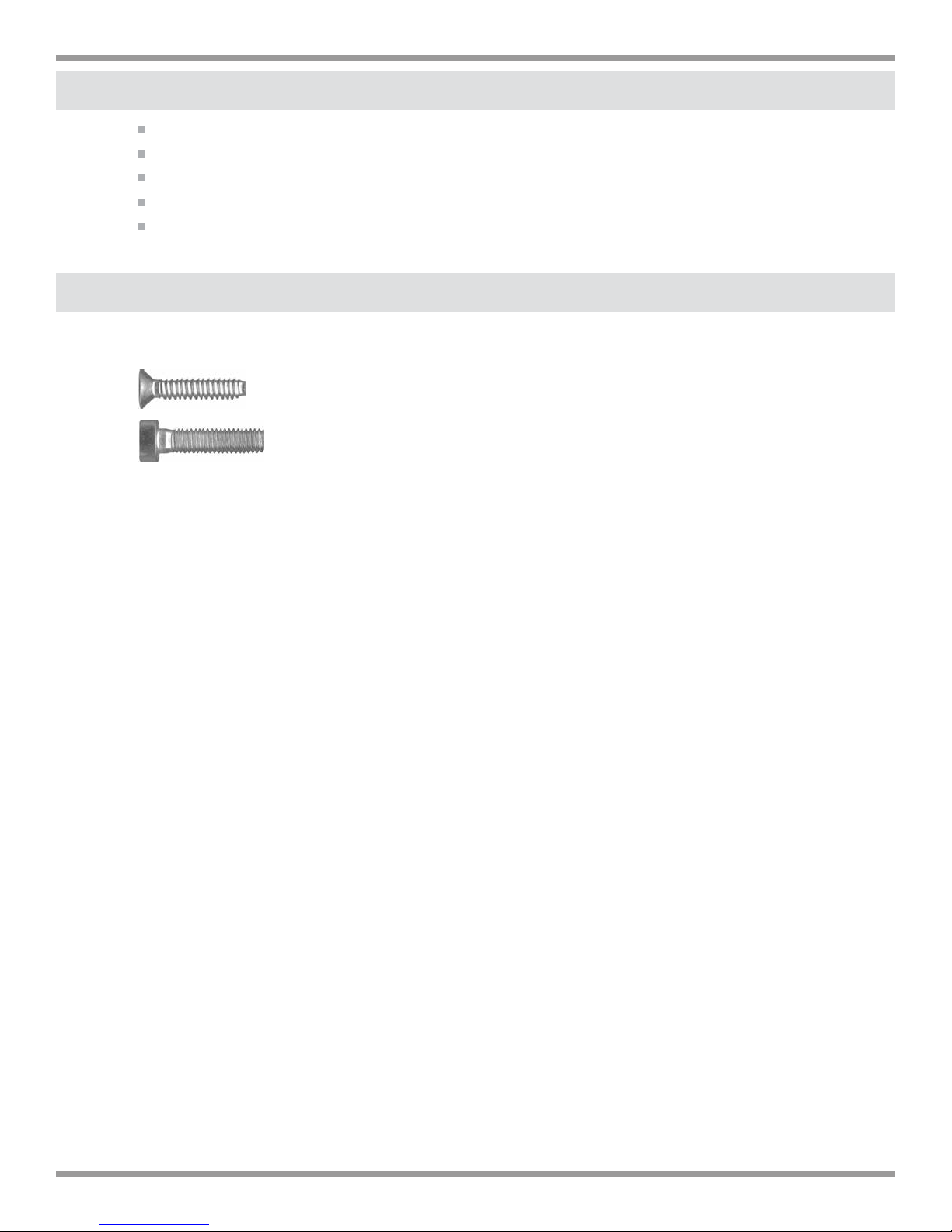
HARDWARE LIST FOR WORKCENTER ASSEMBLY
FRAME
Column Mounting Plate screw T25 20mm
(4 at each end of each column-already installed)
Table Top mounting Allen bolt 5mm (or 4mm) x 25mm
(8) - supplied
4
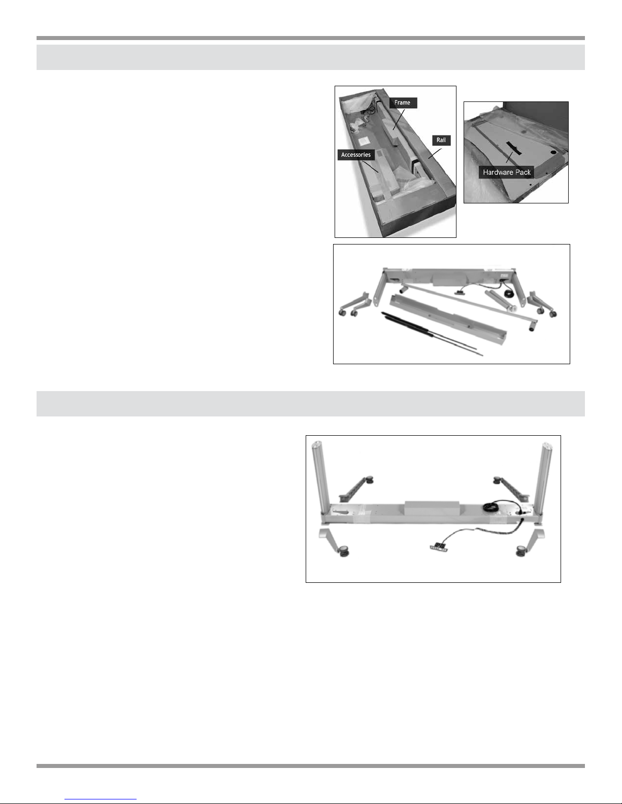
1. COMPONENTS
Box (A) Frame and optional accessories
Box (B) Table top, Support Structure,
Cable Outlets (3)
Unpack and layout all components from
box (A). All the fasteners are in individual
bags taped to the relative component.
(A) Frame
•
•
(B) (2) short feet, (2) long feet
Options:
•
(C) Monitor rail
•
(D) (2) monitor rail posts
•
(E) Cable Tray with or without MBMOU
and power strip
•
(F) Accessory Boxes
Box A
Box B
A
B
D
B
C
E
2. FRAME LAYOUT
Lay frame upside down. The control
•
panel cable always exits the
cross rail at the back of the
frame.
•
Motor housing is ush with the
back side of frame. The angled
side is the front of the frame.
•
The short legs always attach at
back of frame. The long legs
always attach at front of frame.
Front
Back
5

3. FEET ASSEMBLY
•
Using 4mm long T-handle Allen wrench, loosen but do
not remove completely, Allen bolts on foot binding clamp.
(pic. 1.)
•
Align foot and binding clamp in grooves of leg (pic. 2)
and slide down to the numbered markings. (pic. 2a)
•
(pic. 2a) The top of the foot (when frame is turned upright)
should stop on the line between zero (0) and one (1). This
sets the minimum table height to 68cm (26.75”) and will al
low for adequate bottom of frame clearance for most ooring surfaces including carpet.
NOTE: If customer requests a change in height,
you may line up the feet on higher numbers if
you want the minimum table height to be greater
than 68cm. (26.75”)
Each mark represents one (1) cm.
Total range is 10 cm or 4”.
-
pic. 1
Be careful to line up all four feet to the same
number as to make sure the workcenter
is level. (pic. 4)
pic. 2a
pic. 2
pic. 3
pic. 4
6
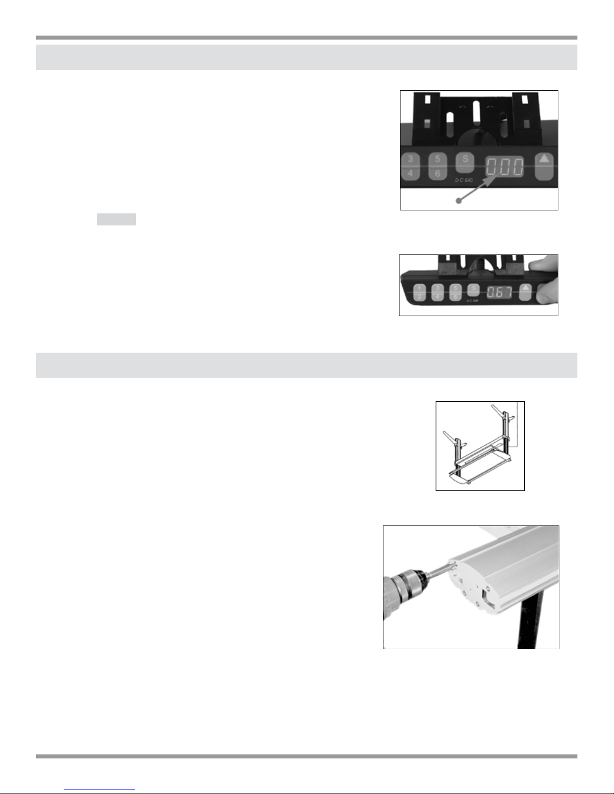
4. RESETTING THE CONTROL PANEL
•
Keeping frame upside down, plug desk in. You will
see blinking zeros on the control panel. (pic. 1)
•
To reset the control panel, press and hold the
down arrow button until column reaches its lowest
position. Continue to press the down arrow until
diplay reads 067 or 068. The workcenter controls
are now reset.
NOTE:You cannot raise the table until you reset
pic. 1
the column at its lowest position.
YOU ARE NOW READY TO RAISE THE TABLE
ASSEMBLY USING THE UP ARROW (^).
pic. 2
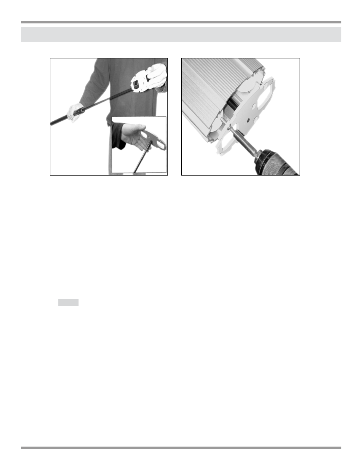
5. GAS SPRING PREPARATIONS (not appliciable if factory installed)
Extend the leg columns completely by pressing
•
and holding the “up” arrow until top reaches 120cm
shown on display. (pic. 3)
•
Remove the cover (stabilizing plate) on the foot
side of the column by loosening the four (4) coun
ter sunk screws. (pic. 4)
-
pic. 3
THE COLUMNS HAVE TO BE COMPLETELY
EXTENDED BEFORE INSTALLING GAS
SPRINGS BECAUSE OF THE RISK OF INJURY
BY THE PRESSURIZED GAS!
pic. 4
7
6. INSTALLATION OF GAS SPRINGS (not appliciable if factory installed)
pic. 1
•
Align the stabilizing plate with the piston rod of the gas spring side of the
pic. 2
plate with countersunk holes facing away from spring.. Plate has to be
rotated clockwise on the piston rod to secure. (pic.1)
•
Center gas spring with stabilizing plate into column and align plate
with (4) screw holes.
•
Mount the plate (pic.2) using the four (4) Torx head countersunk screws and
Torx25 tip. Tighten screws evenly to compress cylinder until plate is ush with
leg column.
Note: Tighten screws slowly in an alternate pattern making sure plate
compresses evenly.
8
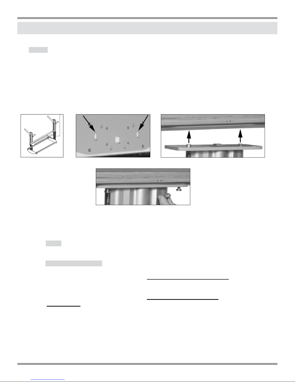
7. ATTACHING TABLE TOP
NOTE: IF THE MODEL NUMBER ENDS IN Z OR ZM: AFTER THE GAS SPRINGS ARE
INSTALLED, THE FRAME HAS TO HAVE APPROXIMATELY 88 LBS OF WEIGHT ADDED
WHILE RAISING OR LOWERING THE TABLE ASSEMBLY.
(TO ADD WEIGHT, LEAN ON FRAME, EXERTING APPROXIMATELY 88 LBS OF PRESSURE
WHILE PRESSING AND HOLDING THE UP OR DOWN ARROW.)
CAUTION: FAILURE TO DO THIS MAY DAMAGE MOTOR OR GEARS.
pic. 1
Align frame with top support structure and attach columns to top (pic 2 with pic 3)
•
pic. 2
pic. 3
pic. 4
with supplied (8) #4 Allen head bolts- 4 per column.
Note: When table top and columns are aligned, the two plates
will be ush.
*Jobsite Conditions:
A. If you are assembling the workcenter in the room where it will reside, you
can assemble the entire unit upside down and then place right side up.
B. If you are assembling the workcenter outside of the room where
it will reside, the control panel cannot be attached to the top until the table top
and leg assembly are placed in the nal room location
9

section two
accessory installation
10
 Loading...