

coronaDesking GO2 Corner WorkCenter Assembly Manual
GO2 Corner WorkCenter
Assembly Manual
1. COMPONENTS
Box (A) Frame and optional accessories
Box (B) Table top, Support Structure, Cable Outlets (3)
Unpack and layout all components from box (A). All the fasteners are in
•
individual bags taped to the relative component.
•
Frame 1 & 2
•
(4) short feet, (2) long feet
Options:
•
Monitor rail
•
(3) monitor rail posts
•
Cable Tray with or without MBMOU and power strip
•
Accessory Boxes
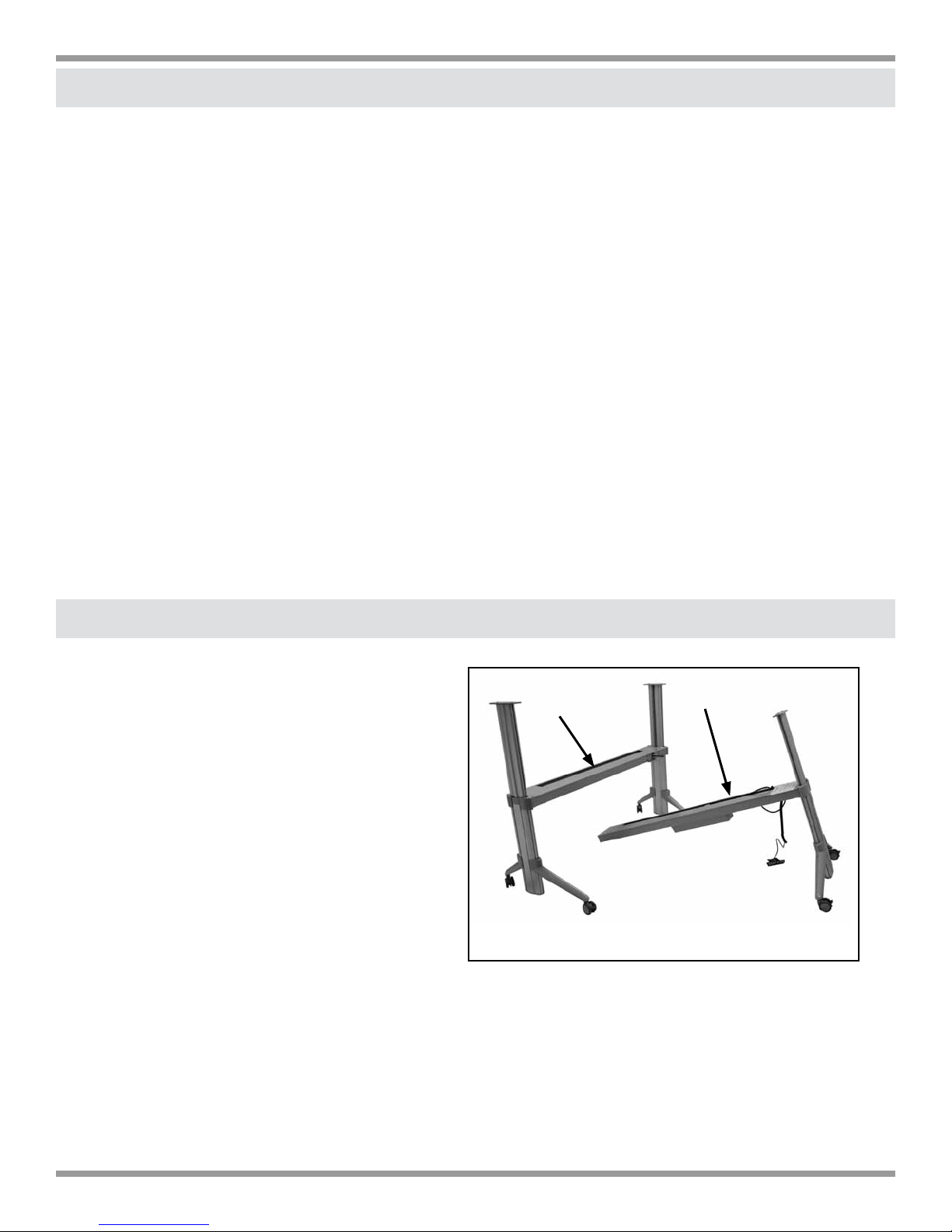
2. FRAME LAYOUT
Position the two frames next to
•
each other. The control panel cable
always exits the cross rail at the
back of the frame.
•
The short feet always attach at
the back of the frame. The long
feet always attach at front of
frame. The center leg always has
2 short feet.
•
Raise legs to the highest position. Remove frame covers from
both cross rails.
eisys/healthcare, inc. corner 10.2010
2
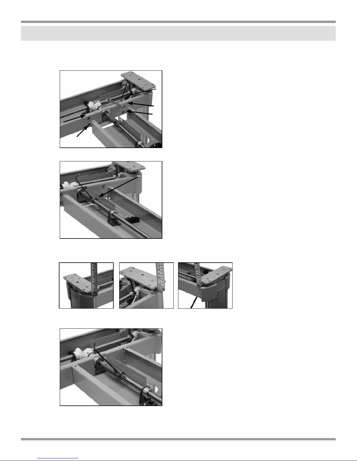
3. ATTACHING THE TWO FRAMES
•
Remove the 6 T25 screws that secure the top of the frame cover
Remove the four screws and nuts indicated from Frame 2.
•
Remove the threaded pin as indicated from Frame 2.
Make sure all three (3) legs are at the exact same height before connecting the
drive shafts together.
Now connect the two drive shafts.
•
eisys/healthcare, inc. corner 10.2010
3
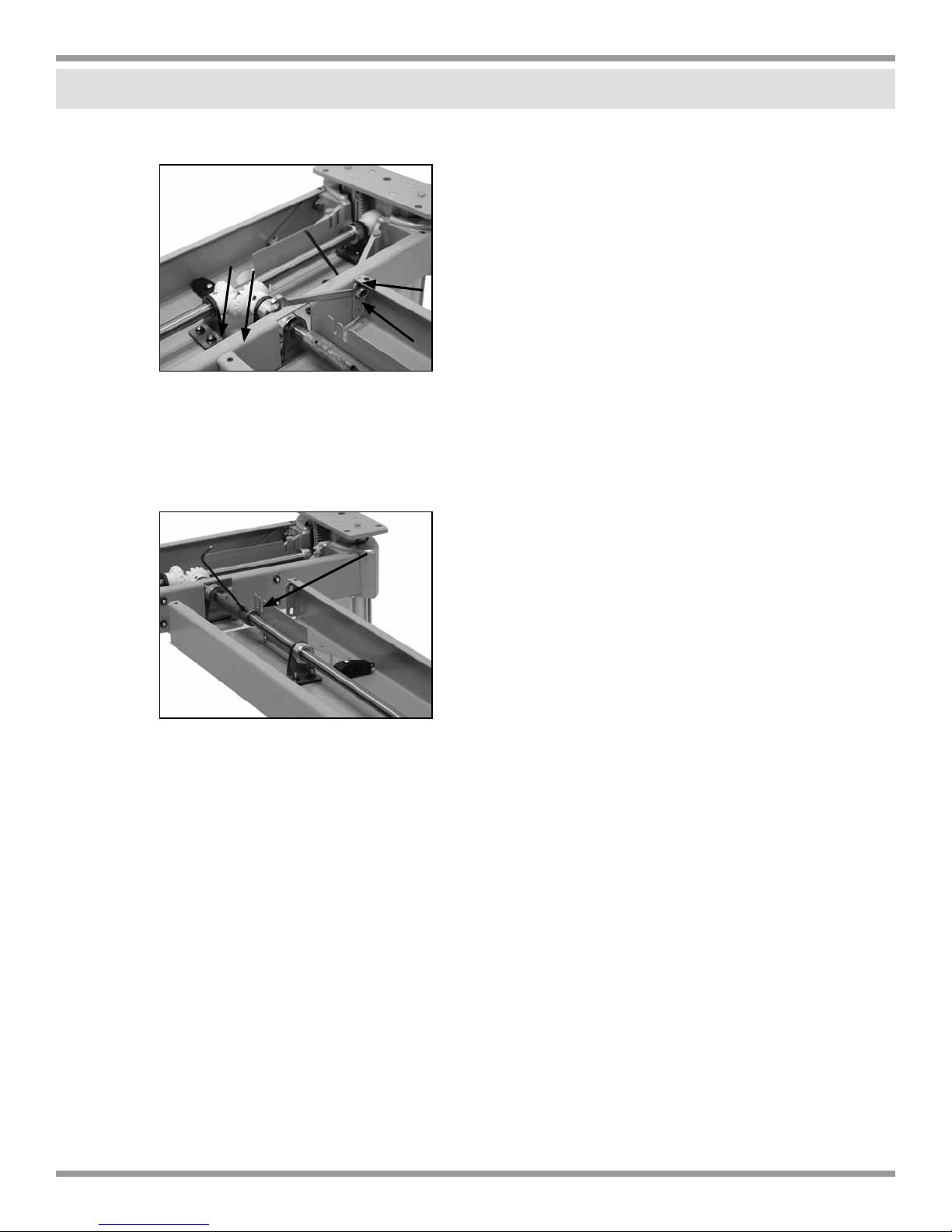
3. ATTACHING THE TWO FRAMES
•
Tighten the four screws and nuts to both frames.
•
Line up the hole in the drive shaft on frame 1 with the hole in the drive shaft of frame 2.
(do this by manually raising and lowering the leg on frame 1; it will move freely because
it is not attached to the motor)
•
Insert threaded pin and tighten.
•
Now raise all three (3) legs to the highest position.
eisys/healthcare, inc. corner 10.2010
4
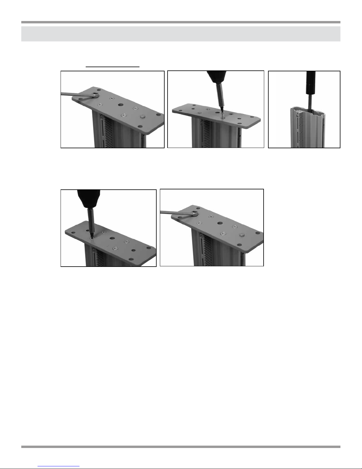
4. INSERTING GAS CYLINDERS
•
Remove top plates on all three legs and insert cylinders (align the bottom of the
cylinder by hand-screwing it into the bottom plate until you cannot turn it anymore)
1. Remove 8mm hex nuts (2)
Re-attach top leg plates (The two hex nuts should only be snug. Securely tighten the
•
2. Remove T25 screws (4) 3. Insert cylinder
4 screws)
1. Replace screws
•
Re-attach cable duct covers and 6 securing screws.
2. Hex nuts should only be snug
eisys/healthcare, inc. corner 10.2010
5
 Loading...