

Page 1
3
x
E
i
ㅁ
МНОЮ,
АННЕ
0$
em
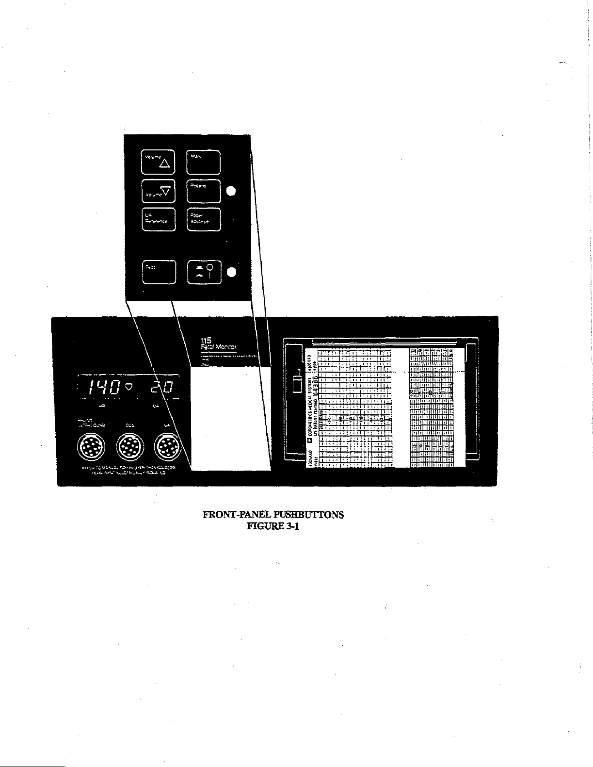
FRONT-PANEL
FIGURE
PUSHBUTTONS
3-1
Page 2

Page 3

SECTION
3
3.0
FRONT-PANEL
Pushbutton
„of
reference.
Volume
These
two
with
the
arrow
causes
the
UA
Reference
Depressing
or
at
10-Relative
Test
The
monitor
Mark
Depressing
CONTROLS
controls
pushbuttons
Refer
found
to
FIGURE
are
pointing
volume
to
this
pushbutton
for the
self-test
this
button
decrease.
routine
causes
CONTROLS,
on
the
front
panel
3-1.
used
to
change
up
(A)
causes
the
Volume
for
.5
tocodynamometer.
is
initiated
an
control
seconds
by
arrow
to
CONNECTORS,
of
the
Model
the
volume
volume
sets
be
to
has
no
the
reference
depressing
printed
115
Fetal
of
sound
increase.
effect
Depressing
on
level
this
pushbutton.
on
the
heart
AND
Monitor
emitted
the
processing
on
the
rate
channel
INDICATORS
are
highlighted
from
the
the
button
used
UA
recorder
of
the
in
rear-panel
to
with
the
compute
speaker.
channel
strip-chart
bold
face
Depressing
arrow
pointing
heart
rate.
at 0 mmHg
paper.
type
down
for
the
below
the
button
(V)
strain
for
ease
gauge
Record
Depressing
button
is
an
If
recorder
the
amber
indicator
restarted
Paper
Depressing
until
Advance
Monitoring
is
released.
Power
When
this
Depressing
this
pushbutton
amber
indicator
door
is
open,
light
chart
paper
this
pushbutton
modes,
pushbutton
the
time,
is
button a second
once
activates
light
which
or
if
no
strip-chart
will
flash.
When
is
inserted.
canses
the
date,
and
chart
depressed,
power
time
the
recorder.
illuminates
paper
the
recorder
recorder
speed
is
applied
tums
off
the
Depressing
while
recorder
is
installed,
is
out
to
advance
information
unit
to
and
chart
the
the
will
unit
this
is
on
the
recorder
of
paper,
paper
be
printed
and a green
indicator
button
again
and
extinguishes
will
the
recorder
at
25
cm/min
onto
indicator
light.
turns
not
activate.
will
for
the
paper
light
off
the
recorder.
when
recorder
If
paper
is
near
automatically
as
long
20
seconds
next
as
to
the
the
stop
button
after
button
Adjacent
is
off.
depletion,
and
cannot
is
held
the
pushbutton
illuminates.
to
the
be
down.
Page 4

a
E
FRONT-PANEL
ES
DISPLAY/CONNECTORS
FIGURE
3-2
.
3-2
Page 5

3.1
FRONT-PANEL
The
front-panel
Heart
Rate
The
heart
rate
heart
rates
are
display
(HR)
Display
being
being
ALPHANUMERIC
window
monitored
monitored
is
is
(duai-cardiotach),
DISPLAYS
depicted
displayed
in
in
FIGURE
beats-per-minute
the
3-2.
display
will
(BPM)
in
correspond
the
left
portion
only
of
the
to
the
PHONO/ULTRASOUND
display
window.
If
two
mode.
Heartbeat
A
heart-shaped
screen.
SOUND
Uterine
A
2¥rdigit
monitoring
mmHg
be
zeroed
Some
when
3.2
The
Indicator
symbol
İf
two
heart
mode.
Activity
(UA)
numerical
or
in
relative
range, a ñashing
upon
depression
older
versions
the
pressure
FRONT-PANEL
three
front-panel
is
PHONO/ULTRASOUND
This ochre
ducer
colored,
plug,
and
electrically
(V)
fiashes
rates
are
being
Display
value
located
units
**
+”?
of
of
the
Model
below
the
CONNECTORS
connectors
12-pin,
input
keyed
with
each
monitored
on
the
right
for
tocotransducer
or
**—*”
will
the
UA
reference
115
Fetal
strip-chart
are
scale
depicted
receptacle
to
identify
detected,
valid
heartbeat.
(dual-cardiotach),
side
of
the
display
measurements.
appear
on
the
display.
control.
Monitor
is
replace
range.
in
FIGURE
mechanically
the
type
of
plug
the
3-2.
keyed
inserted.
The
symbol
this
display
window,
will
correspond
indicates
When a pressure
The
entire
display
UA
Display
to
with
accept
only a Model
is
located
only
uterine
pressure
reading
will
exceeds
flash
““BASELINE
115
at
the
center
to
the
in
or
falls
when
the
PRESSURE
phono
or
of
the
display
PHONO/ULTRA-
mmHg
for
internal
below
the
0-100
transducer
ultrasound
OFF
cannot
SCALE”
trans-
ECG
This
gray
colored,
(dual-cardiotach),
12-pin
and
UA
This
white,
12-pin
to
recognize
which
connector
electrically
receptacle
plug
has
been
is
mechanically
keyed
is
mechanically
inserted.
to
distinguish
keyed
keyed
between
to
accept
to
accept
either
the
the
leg-plate
two.
the
tocotransducer
transducer
or
strain
or
the
maternal
gauge
ECG
and
electrically
cable
keyed
Page 6

3.3
TIME
AND
Three
pushbuttons
button
is
indicated
buttons
capabilities
Select
The
value
to
are
T/D
monitor’s
range
be
changed:
operational
of
as
DATE
located
by
either a utle
only
the
unit
are
internal
shown
the
clock
in
code
TIME/DATE
SET
PUSHBUTTONS
under
the
lip
or
symbol
if
the
TIME/DATE
non-functional
uses a 24
TABLE
number
3-1.
will
appear
of
the
front
immediately
SET
while
this
hour
format.
Successive
on
the
UNIT
OF
Minutes
Hours
Day
Month
Year
PUSHBUTTONS
FIGURE
panel
control
above
switch
on
switch
is
enabled.
Each
unit
depression
extreme
TIME
of
left
(FRONT
3-3
the setting
the
row
the
rear
of
time
and
this
pushbutton
of
the
display
CODE
5
6
7
8
9
PANEL)
of
of
pushbuttons
panel
is
date
permits
screen.
time
and
(refer
in
the
ENABLE
is
identified
selection
RANGE
00-59
00-23
01-31
01-12
83-99
date;
the
to
FIGURE
position.
with a code
of
function
the
of
3-3).
All
and
time
each
push-
These
monitoring
has
an
assigned
or
date
parameter
push-
34
TIME/DATE
TABLE
CODES
3-1
Page 7

(Upwards
Pointing
Arrow)
Activation
in
two
activation
est
(Downwards
Activation
selected
NOTE:
of
digit
of
possible
of
parameter
If a number
will
the
‘‘increase
positions
the
value
the
immediately
pushbutton
and
Pointing
‘‘decrease
occurs.
then
outside
not
activate
value’’
causes
to
Arrow)
vaiue”’
the
and
pushbutton
to
the
“wrap
assigned
the
message
the
right
of
front-panel
around”
pushbutton
value
“SET
increases
the
code
display
to
the
lowest
is
similar
range
of
TIME/DATE”
the
value
number
to
cycle
value
to
the
83-99
of
the
selected
identifying
from
the
again.
““mcrease
is
entered
for
will
be
printed
the
lowest
value””
the
“YEAR”
on
time/date
unit
value
monos
parameter.
of
time
of
the
unit
the
strip-chart
being
selected
except
of
time,
paper.
This
value
changed.
parameter
that
decreasing
the
internal
is
displayed
Continuous
to
its
high-
of
the
clock
3-5
Page 8

4905410
!
i
SYSTEMS
MEDICAL
PENDING
PATENT
US
conomernics
Cİ
om
4305440
3.4
STRIP-CHART
As
depicted
Heart
This
"is
monitored,
trends
PHONO/ULTRASOUND
Uterine
This
scale
of 0 to
Alphanumeric
When
the
HR
addition,
in
this
in
FIGURE
Rate
Channel
channel
channel
from 0 to
is
only
are
printed
Activity
is
100
mmHg.
activated,
and
UA
if
either
margin.
located
located
100;
Channels
the
trend
RECORDER
3-4,
the
strip-chart
on
the
left
one
trend
is
printed
with
different
Channel
on
if a transcervical
recorder
grids.
the
optional
print
mode,
while
the
right
automatically
Other
2115
side
of
the
using
densities
the
side
of
catheter
messages
Keypad
STRIP-CHART
recorder
the
normal
the
prints
relating
or
is a dual-channel
recorder
normal
to
help
print
recorder.
and
externally
time,
2116
Keyboard
RECORDER
FIGURE
and
print
distinguish
density
If a tocodynamometer
date,
to
functions
3-4
is
capable
density.
between
corresponds
mounted
modes
and
is
being
unit
of
printing
When
strain
of
monitoring,
parameter
used,
fited
two
them.
to
the
is
gauge
messages
in
the
right
either
one
HR’s
are
The
darker
ECG
used,
are
used,
and
changes
side
or
two
monitored
print
mode.
readings
paper
keyed
tends
will
are
speed
be
in
by
of
the
monitor.
trends.
When
only
(dual-cardiotach),
trend
corresponds
recorded
are
in
printed
the
in a relative
plotted
over a range
the
margin
as
they
operator
occur.
will
one
HR
the
to
the
between
In
appear
36
Page 9

PA
m
‘nant
>
Garan
TIME/DATE
os
SLOW-BLOW
©
TT
2.50
SPEED
Tİ
AMP
nor
ne
3
anan
SET
swese
FUSE
os
100
和
o
fore
wat
ECG
spare
|
28055)
|
CORQMETRICS
FETAL
COROMETRICS
us
.
MOTDA
MEDICAS
SYSTEM
CEES
CALTION:
VICE
WERNNE
FUSES
aay
MOQEL
NE
=
ELECTRIC
ONLY
TO
TO
AS
MARKED
115
2I0OSERIES
DATA
ea
==)
camon
E,
SHOX
И
АЕ
OUALIFIED
REBUČE
PANE
CONNECT
SÉRIES
409
SYSTEM
COROLAN
MAZARD,
DO
Fer
SER
MÁZARO
лез
TO
OOROMETRICS
MONTORS
ONLY
sener
o
©
TESTER
"©
3.5
REAR-PANEL
Three
switches
ECG
ARTIFACT
This
is a two-position
tion,
the
plate
In
the
ON
position,
not
be
printed.
in
the
OFF
This
switch
CHART
This
SPEED
is a two-position
TIME/DATE
CONTROLS
are
located
ELIMINATION
must
be
any
position,
affects
all
only
SET
at
the
slide
switch
removed,
new
ECG
ECG
values
the
direct
switch
used
upper
that
the
switch
value
will
ECG
to
select
left
is
locked
which
be
mode
comer
of
in
place
changed,
differs
printed
chart
regardless
(FECG
paper speed
REAR
PANEL
FIGURE
the
rear
panel.
with a faceplate
and
the
plate
by
more
than
of
or
MECG).
of 1 cm/min
3-5
Refer
to
and
reversed
+25
BPM
previous
rates.
or 3 cm/min.
FIGURE
two
to
lock
from
3-5.
screws.In
it
in
the
the
previously
order
new
position.
to
change
the
calculated
switch
heart
posi-
rate
will
The
time
toring
capabilities
3.6
REAR-PANEL
There
are
at
the
upper
ing the
location
ECG
(+80db)
This
receptacle
aduit
ECG
and
date
can
of
eight
connector
left
corner
of
each
permits
recorders:
be
set
only
the
unit.
The
CONNECTORS
receptacles
of
the
rear
connection.
recording
|
when
this
DISABLE
on the rear
panel
and
of
direct
switch
position
panel
moving
ECG
signals
is
placed
in
the
is
used
at
of
the
Model
in a clockwise
on
an
external
ENABLE
all
other
115
Fetal
direction.
recorder.
position;
times.
Monitor.
Referring
The
this
simulraneously
They
are
discussed
to
FIGURE
output
level
disables
below,
3-5
will
is
compatible
help
with
all
moni-
beginning
in
clarify-
standard
Page 10

J103
This
receptacle
Leg
Plate
The
internal
is
Tester
ECG
used
to
connect
simulator
used
the
to
test
optional
the
115
Corometrics
Leg
Plate
is
2115
Keypad
connected
or
2116
to
this
receptacle.
Keyboard.
Remote
This
is
the
Headset
This
receptacle
from
the
3102
This
connector
J101
This
is
the
Ground
This
terminal
3108
(Optional)
This
optional
When
the
Mark
input
is
speaker.
is
line
cord
Lug
is
receptacle
option
connector
used
to
connect
used
to
interface with
connector
used
to
provide
is
is
present,
for
the
for
an
used
to
its
connector
Remote
the
AC
Event
Corometrics
the
power.
auxiliary
interface
is
Marker.
headset.
Corometrics
ground
to
located
for
an
external
directly
Insertion
SPECTRA
the
monitor.
computer.
below
of the
400.”
The
the
J103
|
headset
interface
into this
is
connector.
either
RS-232C
connector
will
or
inhibit
sound
COROLAN™.
3.7
REAR-PANEL
Two
fuses
F101
This
fuseholder
Spare
This
faseholder
FUSES
are
located
contains a 1.5
contains a spare
in
the
lower
ampere
left
1.5
corner
SLO-BLO
ampere
of
the rear
fuse.
SLO-BLO
panel.
fuse.
Refer
to
FIGURE
3-5.
3-8
 Loading...