

Page 1
User Manual
User Manual
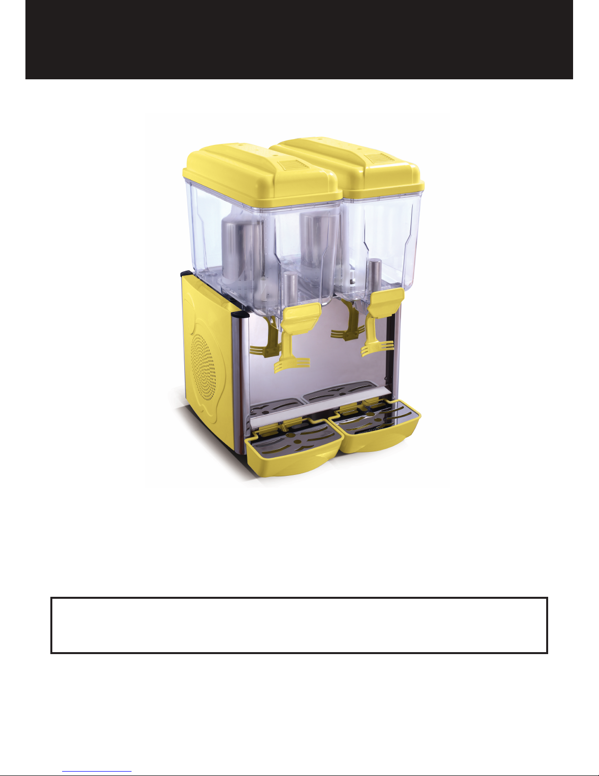
Juice Dispenser
Models: Corolla-1S,Corolla-2S,Corolla-3S,
Royal-1P, Royal-2P,Royal-3P
Please read and keep these instructions. Indoor use only
1
Page 2

User Manual
Index
General information .............................................. 3
2
Parts overview and technical data ....................... 4
Operating instructions ..................................... 5 - 6
Cleaning and maintenance .......................... 7 - 8
Wiring diagram ................................................... 9
Trouble shooting ..................................................10
Warranty information ...........................................10
Page 3
Important Safeguards
1. When using electrical appliances, basic safety precautions should always be
followed including the following:
2. Read all instructions
3. Close supervision is necessary when any appliance is used by or near children.
4. Make sure the appliance is OFF when not in use, before putting on or taking off
parts, and before cleaning.
5. Do not operate any appliance with a damaged cord or plug or after the appliance
malfunctions, or is dropped or damaged in any manner. Return appliance to the
nearest authorized service facility for examination, repair or electrical or mechanical
adjustment.
6. Do not use outdoors.
SAVE THESE INSTRUCTIONS
3
Useful instruction for transport
the cooling circuit, it is necessary to always carry, store and handle the machine in
a vertical position, following the instructions found on the packaging.
2. If the machine was accidentally or purposely placed in a non-vertical position during
transport, before operating the machine, it should be kept in a straight position for
Unpacking: Remove cardboard and plastic covering. Make sure that the machine
Important: The various packaging should be kept from Children since they are
potentially dangerous. Dispose the Packaging according to the regulations from the
local authorities.
Page 4
User Manual
4
Model
Capacity
Voltage (V)
(Hz)
Power (W)
Dimension
(CM)
Gas
Corolla-1S
Corolla-2S
Corolla-3S
Royal-1P
Royal-2P
Royal-3P
1 x 12L 380 23x43x64 R290
R290
R290
R290
R290
R290
2 x 12L 400 43x43x64
3 x 12L 520 63x43x64
23x43x64
43x43x64
63x43x64
1 x 12L 380
2 x 12L 392
3 x 12L
220-240~/50
220-240~/50
220-240~/50
220-240~/50
220-240~/50
220-240~/50
520
Model
Capacity
Voltage (V)
(Hz)
Power (W)
Dimension
(CM)
Gas
Corolla-1S
Corolla-2S
Corolla-3S
Royal-1P
Royal-2P
Royal-3P
1 x 12L 330 23x43x64 R134a
R134a
R134a
R134a
R134a
R134a
2 x 12L 340 43x43x64
3 x 12L 510 63x43x64
23x43x64
43x43x64
63x43x64
1 x 12L 346
2 x 12L 372
3 x 12L
220-240~/50
220-240~/50
220-240~/50
220-240~/50
220-240~/50
220-240~/50
558
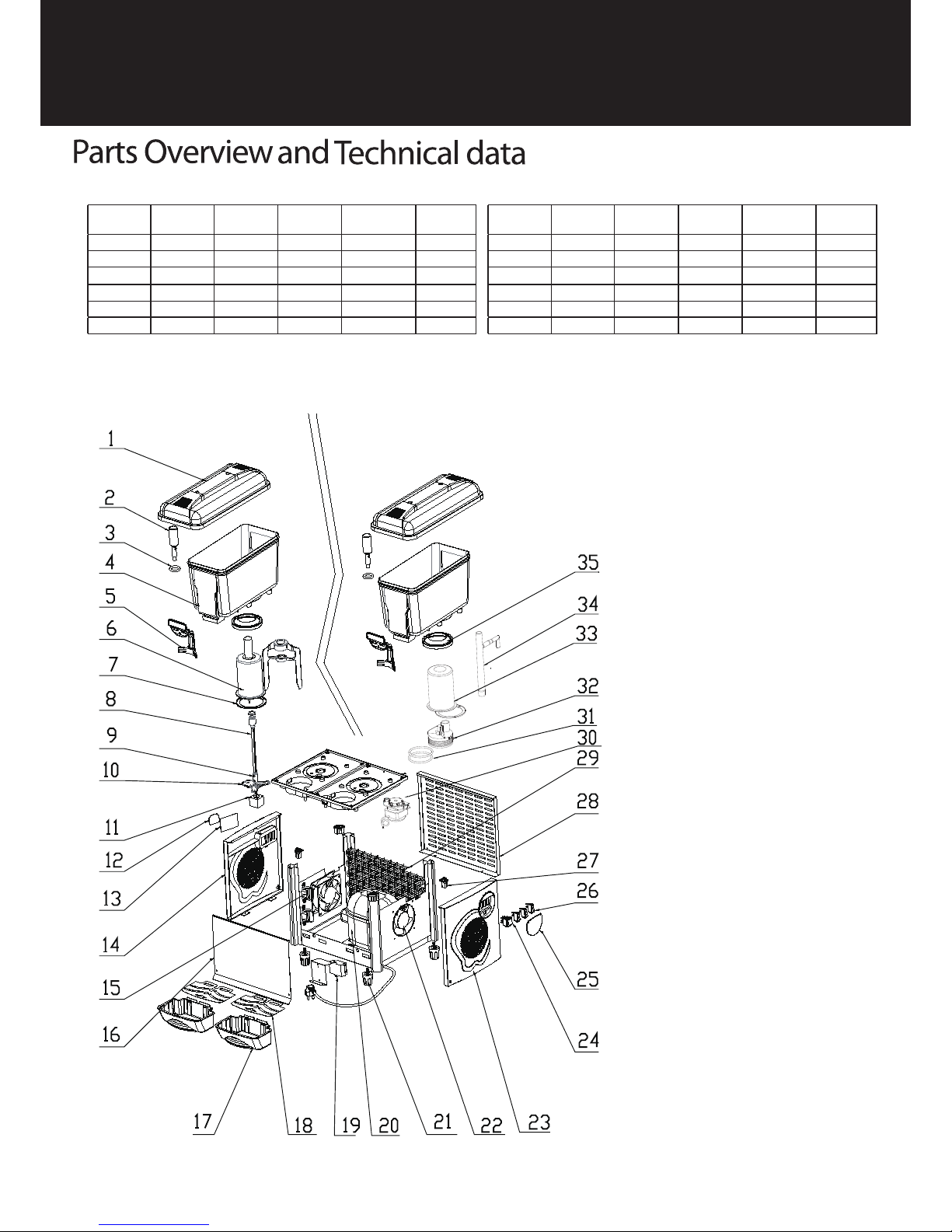
Structure Diagram
PADDLES SYSTEM
PUMP SYSTEM
1. Cover
2. S/s valve
3. Tap gasket
4. Tank
5. Tap level
6. Evaporator
7. Washer of evaporator
8. Shaft
9. Coupler
10. Motor mounting plate
11. Motor
12. Control panel sticker
13. Controller
14. Left side panel
15. Transformer
16. Front panel
17. Water tray
18. Lid of water tray
19. Main box
20. Compressor
21. Adjustable leg
22. Axial flow ventilator
23. Right side panel
24. Power switch
25. Cover for switches
26. Switch for mixing motor
27. Corner plug
28. Back panel
29. Condenser
30. Pumping motor
31. Gasket for pumping motor
32. Pump
33. Evaporator
34. Pumping pipe
35. Gasket for bowl
Page 5
Operating Instructions
5
Positioning
1. Do not install the appliance in the area where
a water jet could be used.
2. Place machine on a horizontal and sturdy
surface.
3. Please install the appliance in locations
where it can be overseen by trained
personnel.
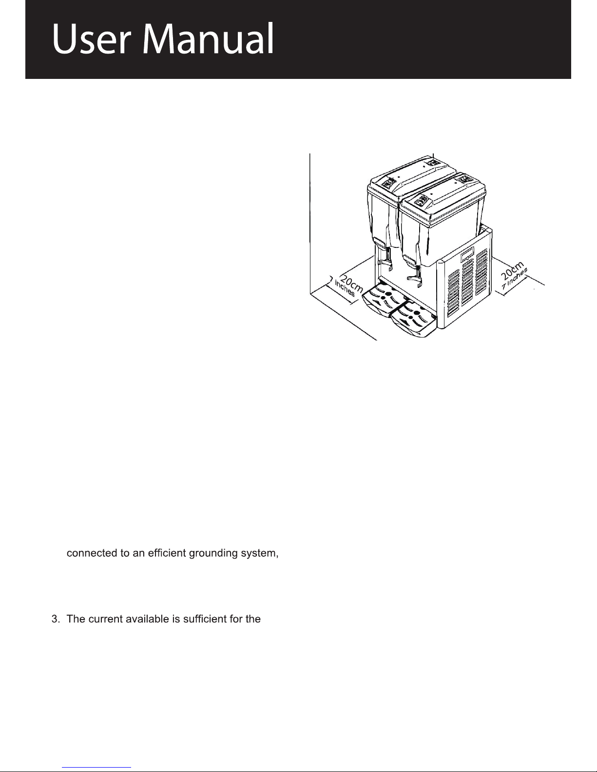
4. For good ventilation, keep a distance of
20cm(7 inches), between unit and walls or
other objects. Increase the distance if the
obstacles are a heating source. When the
dispenser is in place, adjust the legs in order
to keep it level. (FIG.1)
Assembling
1. Remove the cover from the tank.
2. Hang the waste liquid container to hanging
holes on front panel.
3. Insert the taps (with gasket) to the tank and
through the tap lever
Electrical connection
Before inserting the plug into the electrical
socket, carefully read the following precautions:
1. Make sure that the machine is properly
in compliance with current safety standards.
2. Make sure that the voltage is in accordance
with what indicated on the “serial number“
label applied on the chassis.
maximum required by the machine.
4. If necessary, use only approved multiple
outlets, in compliance with current safety
standards.
If in doubt, consult only specialized technicians.
By law, the machine must always be
grounded.
Fig. 1
Page 6
Operating Instructions
6
How To Use:
Before using, the tanks and taps of the
appliance should be cleaned carefully
Refilling
To ensure correct usage of the machine ensure
that the liquid level of the tank does not go
below 3-4 Qt (please use the level lines on the
tank for reference).
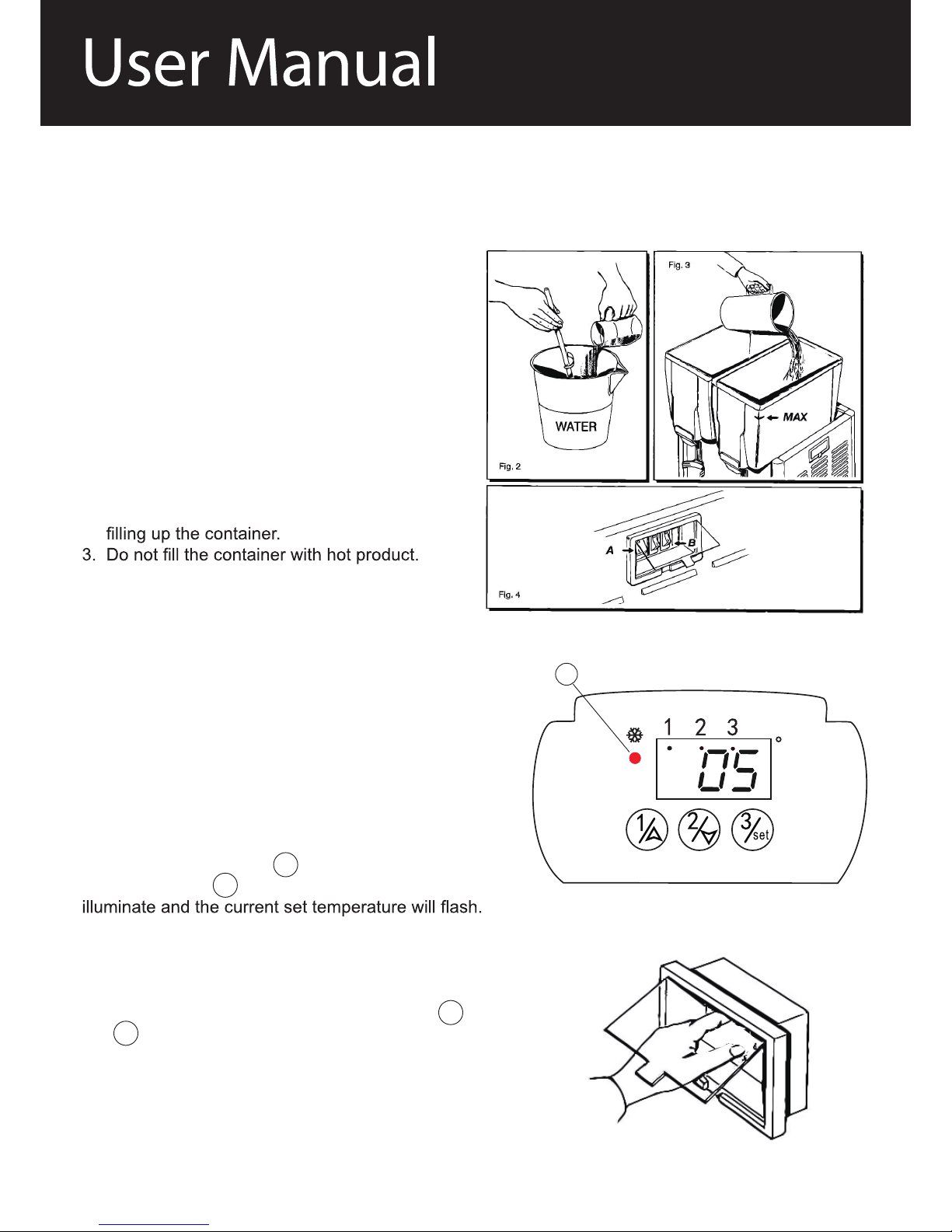
1. Mix product in a separate container (FIG. 2).
2. Make sure to unplug the appliance before
4. Do not let liquid level exceed the “MAX” level
line (FIG. 3).
Beverage Temperature Adjustment (FIG.5)
To adjust the temperature of each individual bowl,
lift up the plastic cover on left side of
the unit. Bowl 1 is on the left hand side of the unit
when looking from the front.
1. Turn on the main switch on the right hand of the
unit. The main power light (A) will now
indicate on the digital control.
2. To set the temperature of bowl no.1
press the button marked 1 twice. The indicator
lamp under bowl 1 at the top of the display will now
Adjust the arrow keys to set the desired temperature
and then press “set”. The temperature range may
be set between 2°C and 8°C.
The control temperature for bowl 1 is now set.
Repeat the process using the buttons marked 2
and 3 to set the temperature of the remaining
bowls.
3. When in operation the unit will automatically
display the actual temperature of each bowl for 2
seconds as indicated by the lamp beneath the bowl
symbols.
Fig. 5
A
C
Page 7
User Manual
Cleaning and Maintenance
7
Observe the ambient temperature
The appliance is suitable for an ambient temperature ranging between 16°C - 32°C.
Cleaning
For health standard and good quality of beverages, clean tanks, lids and the mixing paddles / pumps
as often as possible.
Caution: Do not clean the appliance by water jet.
3. Use neutral soap and a little warm water to wash container, lid, mixing paddles/pump, refrigerator
tank and tap. Rinse carefully with water in order to remove any soap residue.
deposits forming.
5. Pour out the waste water in waste liquid reservoir and clean it as often as possible.
Caution:
Do not use any organic solvents (petrol, alcohol, etc.) for cleaning the appliance. The case of the
appliance may be damaged and explosive vapours may develop. Do not use any sharp edged
objects for cleaning.
The appliance may be cleaned with a damp towel, but may never be immersed in water.
After cleaning the appliance make sure that it will be dried completely.
Beverage Temperature Adjustment (FIG.5)
4. The motor and stirrer for each bowl can be operated
independently using the relevant switch on the right hand
side of the unit.
5. To switch off the cooling to a selected bowl, press the
relevant bowl number on the control panel for 3 seconds.
The letters “OFF” will display for the bowl number selected.
To turn on the cooling press and hold for 3 seconds.
Page 8
Cleaning and Maintenance
8
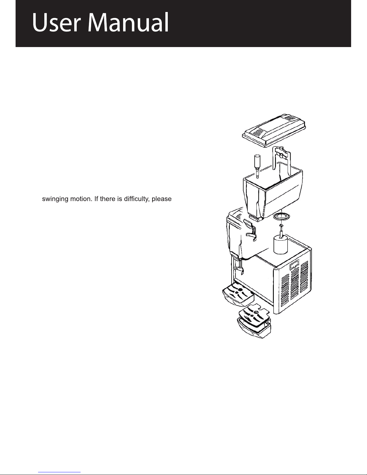
Disassembling and Assembling the tanks:
To disassemble and assemble the tanks or to
change the rubber tank gaskets :
1. Disconnect the unit by removing the plug.
2. Remove the cover from the tank.
3. Remove the mixing paddle from its shaft. For
the pump disassembling follow the instructions
reported on the diagram (Fig.6).
4. Lift container with both hands by a light,
wet the cooling column and gasket.
5. To remove tap, lift it from its setting.
6. Change the gaskets for tanks and taps only
with the genuine gaskets that are supplied by
an authorised supplier.
To reassemble the unit, repeat the above
operations in reverse.
Fig. 6
Page 9
9
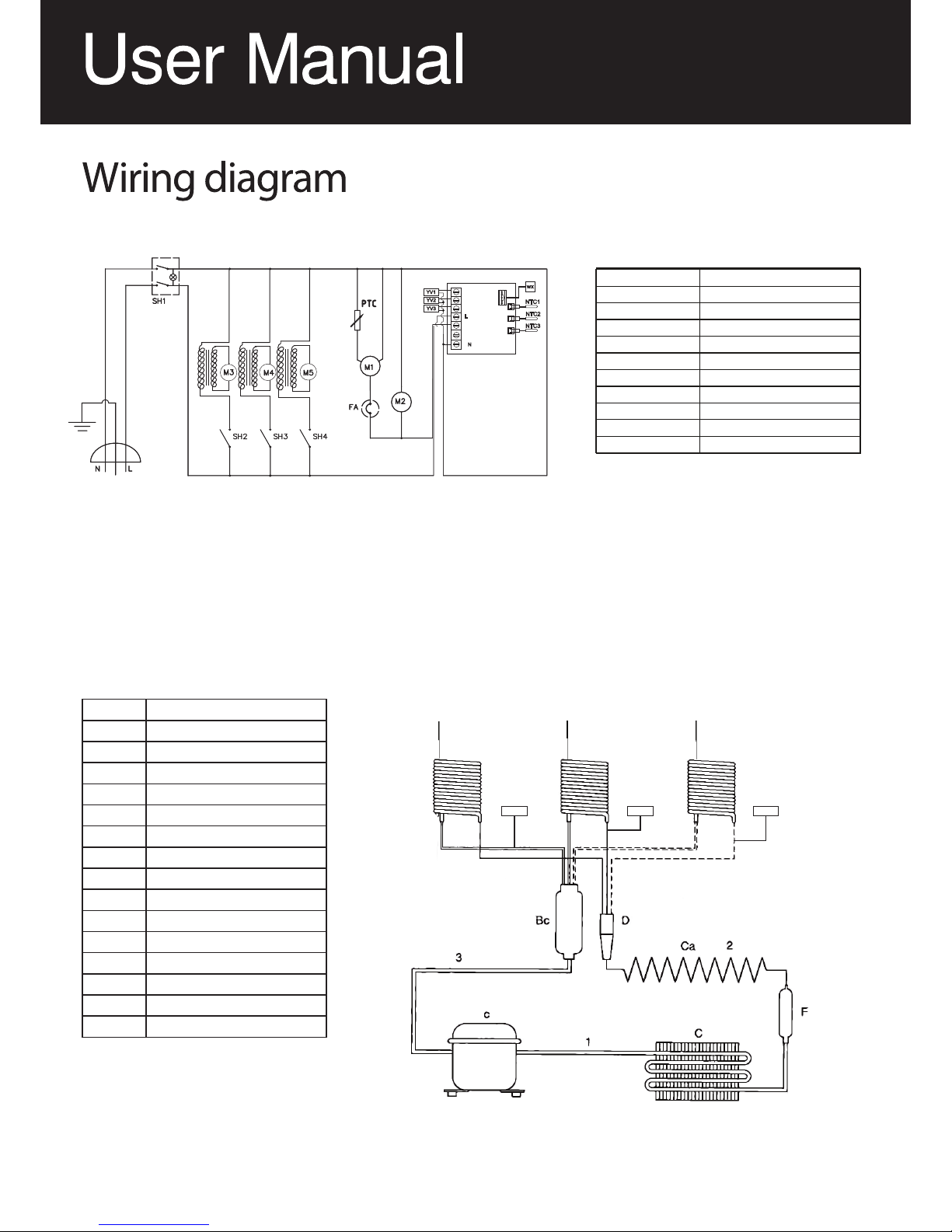
c Compressor
C Condenser
F Filter
Bc Boiler
E1 Evaporator
E2 Evaporator
E3 Evaporator
D Distributor
Ca Capillary coils
1 High Pressure Side
2 Liquid Line
3 Low Pressure Side
YV1 Solenoid valve
YV2 Solenoid valve
YV3 Solenoid valve
Item Description
NTC1
NTC2
NTC3
wx
YV1
YV2
YV3
N
L
LEGEND DESCRIPTION PART NUMBER
SH1 POWER SWITCH
SH1
SH2 / SH3 / SH4 MOTOR SWITCH
M3 / M4 / M5 PUMP MOTOR
WX TEMPERATURE DISPLAY
NTC1 /NTC2 / NTC3 BOWL TEMPERATURE SENSOR
M1 COMPRESSOR
YV1 / YV2 VALVE
FA OVERLOAD PROTECTOR
M2 CONDENSER FAN MOTOR
3 BOWL JUICER
220-240V~ / 50Hz
LEGEND DESCRIPTION
PART NUMBER
SH1 POWER SWITCH
SH1
SH2 / SH3 / SH4 MOTOR SWITCH
M3 / M4 / M5 PUMP MOTOR
WX TEMPERA
NTC1 /NTC2 / NTC3 BOWL TEMPERA
M1 COMPRESSOR
YV1 / YV2 VALVE
FA OVERLOAD PROTECTOR
M2 CONDENSER FAN MOTOR
3 BOWL JUICER
/ YV3
SOLENOID VALVE
PLEASE NOTE:
Switch SH4, Solenoid valve YV3, Probe NTC3
are only used on RBD-33 3 Bowl model
NTC1 NTC2
NTC3
YV1 YV2 YV3
SCHEMATIC: 3 BOWL VERSION SHOWN.
LEGEND DESCRIPTION
SH1 POWER SWITCH
SH2 / SH3 / SH4 MOTOR SWITCH
M3 / M4 / M5 PUMP MOTOR
WX TEMPERATURE DISPLAY
NTC1 /NTC2 / NTC3 BOWL TEMPERATURE SENSOR
M1 COMPRESSOR
YV1 / YV2 VALVE
FA OVERLOAD PROTECTOR
M2 CONDENSER FAN MOTOR
/ YV3
SOLENOID VALVE
PLEASE NOTE:
Switch SH4, Solenoid valve YV3, Probe NTC3
are only used on Corolla-3S 3 Bowl model
T1 TRANSFORMER
Page 10
User Manual
Troubleshooting
Trouble Possible Causes Solution
The axles can’t work when
operating the machine
Poor contact of the electrical
equipment
Check the Plug
The mixing bowl is out of position Moving direction is not correct Change
Leaks oil Sealing washer is damaged Change
Clean the slideway and lubricate
The motor is overheated
and speed is down
The voltage is not enough, or
incorrect speed
Check the voltage or use
lower speed
Noise and overheating Poor lubrication Add or change lubrication
Mixer touches bowl The mixing device or bowl de -
formed
Repair or change the bowl
or mixing device
Limited Warranty
Cleaning
before changing speed in order to avoid damage to the gear bo
DISCONNECT THE MACHINE FROM THE POWER SOURCE BEFORE CLEANING.
!
All new mixer bowls and accessories including, whips, beaters and dough hooks should be properly washed before use.
n with
clean water. It is highly recommended this cleaning procedure is followed for bowls and accessories prior to whipping egg whites or
whole eggs. The mixer should be cleaned daily with a clean damp cloth.
If the unit has not been used for some time it is recommended that the procedure above is followed before mixer use.
It is important that the rear bowl lift guides are greased every three months to prevent corrosion.
WARNING:
10
Royal-Kincool Refrigeration Equipment Co., Ltd
Version: 1.0
Juice dispenser model: Corolla series, English manual
Released date: 2005.10.27
Connecting to a fresh life
Trouble shooting:
Symptom
Possible reasons
Solution
Remark
No power to
machine
Plug is not in.
Insert plug into mains socket
Main switch is not on the “I”
position.
Switch main switch to “I” position.
Power cord is broken.
Replace power cord
Ask for
authorized
service
department
to check and
repair it.
Main switch is broken.
Replace main switch
Machine is
not cooling
Compressor does not start
See “compressor does not start”
section.
Gas leak into the cooling
circuit.
Find leak, filter it out and re-charge
the cooling circuit
Condenser is clogged.
Clean the condenser
Fan motor is burnt.
Replace fan motor
Lack of air flow
Increase distance between the
machine and other obstacles /
heating sources
Compressor
does not
start
Main switch is broken
Replace main switch
Ask for
authorized
service
department
to check and
repair it.
Compressor protector is
broken.
Replace compressor protector
Compressor relay is broken
Replace compressor relay
Compressor motor is broken
Replace motor
One tank is
not cooling
Gas leak into the cooling
circuit
Find leak, filter it out and re-charge
the cooling circuit
Condenser is clogged
Clean the condenser
Lack of air flow
Increase distance between the
machine and other obstacles /
heating sources
Tube of the cooling circuit is
clogged.
Cut the tube, eliminate clog,
re-charge the cooling circuit
Filter is clogged
Replace the filter
The mixing
paddles are
not working
The mixing motor is broken
Replace the mixing motor
Trouble Possible causes Solution
Any necessary repairs to the machine should be undertaken exclusively by an authorized repair
center,using original replacement parts.
The electrical cord should not be replaced by the user.
When the machine is no longer in use, it is recommended that it be made inoperable by
unplugging the machine and cutting the electrical cord.
 Loading...