

Page 1
MODEL #CSE-ATV
1500 LB. CAPACITY
ATV LIFT
PARTS BREAKDOWN AND OPERATING MANUAL
OWNER/USER RESPONSIBILITY:
The owner and/or user must have a thorough understanding of
the manufacturer’s operating instructions and warnings before
using the lift. Personnel involved in the use and operation of
equipment shall be careful, competent, trained, and qualified
in the safe operation of the equipment and its proper use
when servicing motor vehicles and their components. Warning
information should be emphasized and understood. If the
operator is not fluent in English, the manufacturer’s instructions
and warnings shall be read to and discussed with the operator in
the operator’s native language by the purchaser/owner, making
sure that the operator comprehends its contents.
Owner and/or user must study and maintain for future reference
the manufacturer’s instructions and pertinent warning information.
Owner and/or user is responsible for keeping all warning labels
and instruction manuals legible and intact. Replacement labels
and literature are available from the manufacturer.
MAINTENANCE AND INSPECTION:
Visual inspection should be made before each use of the lift,
checking for leaking hydraulic fluid and damaged, loose or
missing parts. Each lift must be inspected by a manufacturer’s
repair facility immediately, if accidentally subjected to an
abnormal load or shock. Any lift which appears to be damaged in
any way, found to be badly worn, or operates abnormally MUST
BE REMOVED FROM SERVICE until necessary repairs are made
by a manufacturer’s authorized repair facility. It is recommended
that an annual inspection of the lift be made by a manufacturer’s
authorized repair facility and that any defective parts, decals or
warning labels be replaced with manufacturer’s specified parts.
A list of authorized repair facilities is available from
the manufacturer.
This operaTing manual conTains
imporTanT safeTy informaTion.
read carefully and undersTand
informaTion before operaTing Tool.
save This manual for fuTure use.
all
PRIOR TO OPERATION:
1. Press release pedal.
2. Pump foot pedal 6 full strokes to purge the air from the
pump and valving.
3. Remove foot from release pedal.
4. Pump the foot pedal until the jack has reached full extension.
Continue to pump several times to purge air from under the
ram.
5. Press release pedal and push ram into its lowest position.
Take foot off release pedal and operate normally.
Note: If the jack responds immediately to pump action, it is free
of air and ready for operation. If not, repeat procedure.
SPECIFICATIONS:
Capacity . . . . . . . . . . . . . . . . . . . . . . . . . . 1500 Lbs. Maximum
Minimum Height
Maximum Height
Base Size
Shipping Weight
. . . . . . . . . . . . . . . . . . . . . . . . . . . . . . . 4-3/4"
. . . . . . . . . . . . . . . . . . . . . . . . . . . . . . 16-1/2"
. . . . . . . . . . . . . . . . . . . . . . . . . . . . . . 17" x 36-1/4"
. . . . . . . . . . . . . . . . . . . . . . . . . . . .101.4 Lbs.
DO NOT EXCEED LOAD RATING OF 1500 LBS.
SECURE LOAD TO TIE-DOWN LOOPS.
USE ONLY ON HARD LEVEL SURFACES CAPABLE OF
SUPPORTING THE LOAD. USE ON OTHER THAN HARD, LEVEL
SURFACES MAY RESULT IN POSSIBLE LOSS OF LOAD.
CSE-ATV — OPERATING MANUAL AND PARTS LIST 1 rev. 07/27/07
NO ALTERATIONS TO THE ATV/MOTORCYCLE LIFT SHALL
BE MADE.
READ, STUDY AND UNDERSTAND THE OPERATING ANUAL
PACKED WITH THIS LIFT BEFORE OPERATING JACK AND/OR
LIFT. FAILURE TO HEED THESE WARNINGS MAY RESULT IN LOSS
OF LOAD, DAMAGE TO THE LIFT, AND/OR FAILURE RESULTING
IN PROPERTY DAMAGE, PERSONAL OR FATAL INJURY.
Page 2

ASSEMBLY INSTRUCTIONS:
1. Secure the hydraulic ram (Part #20) to the base frame with
the screws provided. Make sure the release valve is facing
outside the frame.
2. Insert the foot pedal (Part #21) into the hole over the pump
piston and secure it with the bolt (Part #22). Insert a pivot
pin through the two holes in front of the release valve and
through the release valve pedal. Secure it with the hair
pin provided.
3. Place the safety bar (Part #28) inside the load frame and
align them with the holes on the frame. Insert two securing
bolts through the three of them and secure it with the hair
pin provided.
4. Raise the load frame by hand and align the head of the
hydraulic ram with the holes in the middle of the load
frame. Secure it with the pivot pin (Part #24) provided.
5. Insert the pulling handle (Part #26) into the hole on the
outside of the load frame and turn the handle to lock
into place.
OPERATING INSTRUCTIONS:
1. Make sure lift is on solid, level surface before use.
2. Adjust jack position to make sure the ATV or motorcycle is
centered before lifting.
3. To raise, pump foot pedal (Part #21).
4. Engage the safety bar once the load has reached its
desired height.
5. Before performing any maintenance or adjustments on ATV
or motorcycles, secure the load to lift by connecting two tie
down straps supplied with lift to eyelets on the frame and
hooking other end of straps into eyelets on opposite end of
frame. Adjust straps using clamp until snug.
6. Before lowering, disengage the safety bar by pulling the bar
toward the load frame (Part #25). Loosen and remove tie
down straps.
7. To lower, press the release valve pedal (Part #17) slowly.
WARRANTY COVERAGE
Cornwell Quality Tools Company (“Cornwell”) warrants against defects in material and workmanship on this product for a period of
TWO (2) YEARS from the date of original retail purchase. Subject to the conditions and limitations set forth below, Cornwell will, at its
option, either repair or replace any part of the product(s) that proves defective by reason of improper workmanship or materials.
This warranty does not cover any damage to this product that results from accident, abuse, misuse, natural or personal disaster, or any
unauthorized disassembly, repair, or modification. Repairs, disassembly and modification are only authorized to be made by Cornwell
or a warranty service center approved by Cornwell.
WARRANTY SERVICE
To obtain warranty service, contact your Cornwell dealer.
EXCLUSIONS AND LIMITATIONS
THIS WARRANTY AND THE REMEDIES SET FORTH ABOVE ARE EXCLUSIVE AND IN LIEU OF ALL OTHER WARRANTIES, REMEDIES
AND CONDITIONS, WHETHER ORAL OR WRITTEN, EXPRESS OR IMPLIED. CORNWELL SPECIFICALLY DISCLAIMS ANY AND ALL
IMPLIED WARRANTIES, INCLUDING, TO THE EXTENT PERMITTED BY APPLICABLE LAW, ANY WARRANTIES OF MERCHANTABILITY
AND FITNESS FOR A PARTICULAR PURPOSE. IF CORNWELL CANNOT LAWFULLY DISCLAIM IMPLIED WARRANTIES UNDER THIS
LIMITED WARRANTY, ALL SUCH IMPLIED WARRANTIES ARE LIMITED IN DURATION TO THE DURATION OF THIS WARRANTY.
IN NO EVENT SHALL CORNWELL BE LIABLE TO THE PURCHASER OR TO THE USER OF A CORNWELL PRODUCT FOR ANY SPECIAL,
INCIDENTAL OR CONSEQUENTIAL DAMAGES BASED UPON BREACH OF WARRANTY, BREACH OF CONTRACT, NEGLIGENCE, TORT,
OR ANY OTHER LEGAL THEORY. SUCH DAMAGES INCLUDE, WITHOUT LIMITATION, EXPENSES, LOST REVENUES, LOST SAVINGS,
LOST PROFITS, OR ANY OTHER INCIDENTAL OR CONSEQUENTIAL DAMAGES ARISING FROM THE PURCHASE, USE OR INABILITY
TO USE THE CORNWELL PRODUCT.
Some states do not allow the exclusion or limitation of incidental or consequential damages or exclusions or limitation on the duration
of implied warranties or conditions, so the above limitations or exclusions may not apply to you. This warranty gives you specific legal
rights, and you may also have other rights that vary by state.
Repair kits and replacement parts are available for many Cornwell products, regardless of whether or not the product is still covered
by a warranty plan.
Cornwell Quality Tools Company
667 Seville Road • Wadsworth, OH 44281-1094
CSE-ATV — OPERATING MANUAL AND PARTS LIST 2 rev. 07/27/07
Page 3
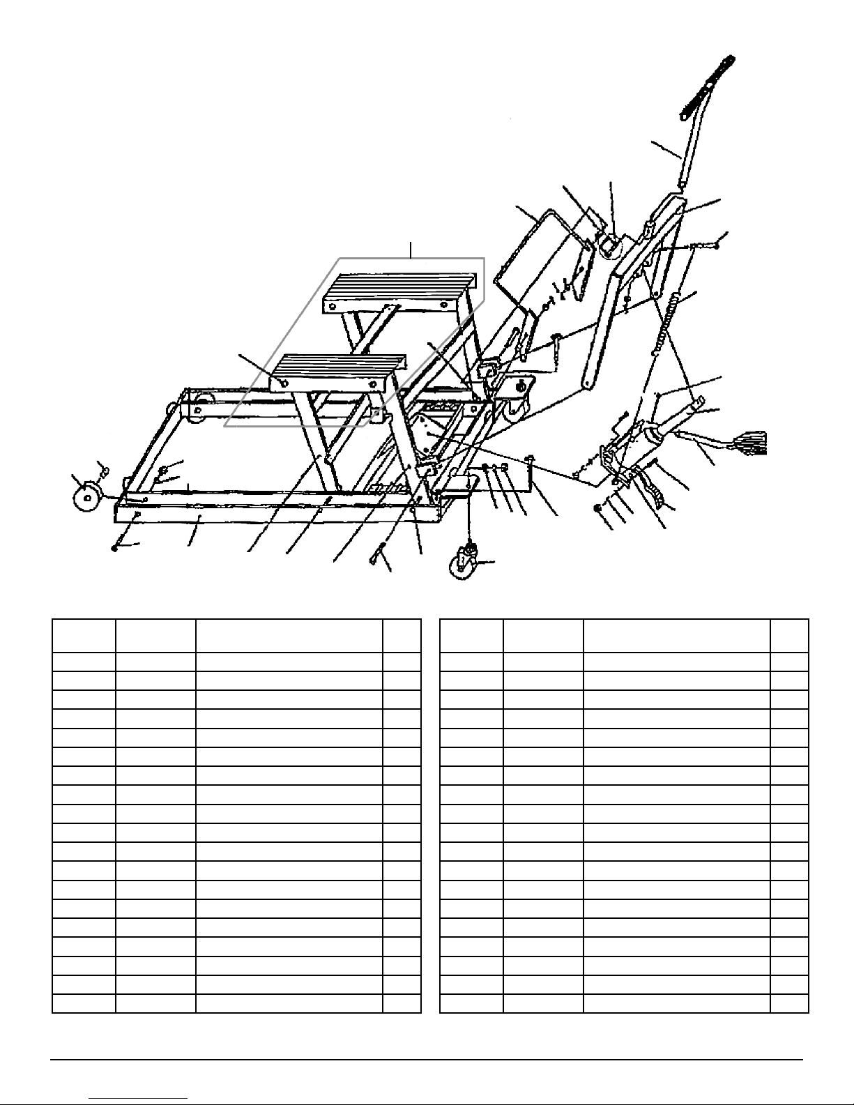
MODEL # CSE-ATV
1500 Lb. Capacity
ATV Lift
26
30
28
36
8
9
29
8
33
35
1
2
3
34
5
8
13
4
7
37
8
9
32
12
8
31
9
11
15
14
27
25
24
23
22
20
21
18
5
10
6
17
16
19
REF
NUMBER
PART
NUMBER DESCRIPTION QTY
1 Sleeve Bearing 2
2 RS661502 Wheel (with sleeve bearing) 2
3 Bolt M8 x 65 2
4 Base 1
5 Washer 8 4
6 Nut M8 2
7 Pin 1 2
8 Washer 12 15
9 Split Pin 7
10 Spring Washer 8 2
11 RS661511 3" Caster 2
12 Pin 2 2
13 Spring Washer 12 2
14 Nut M12 2
15 RS661515 Wheel Stop Bolt 2
16 Pin 1
17 RS661517BL2 Release Pedal 1
18 Bolt M8 x 20 1
19 C-clip 8 1
REF
NUMBER
PART
NUMBER DESCRIPTION QTY
20 RS661520BL2 3 Ton Ram 1
21 RS661521BL2 Foot Pedal 1
22 Bolt M8 x 20 1
23 RS661523 Spring 1
24 Lock Pin 1
25 Load Frame 1
26 Handle 1
27 Clevis Pin 14 x 60 1
28 Safety Bar 1
29 Washer 1 2
30 Washer 2 2
31 Pin 3 2
32 Rear Strut Linkage 1
33 Lock Nut M12 4
34 Lock Nut M8 2
35 Bolt M12 x 115 4
36 RS661536 Platform 1
37 Front Strut Linkage 1
Not Shown RS6615TD Tie Down Strap
2
CSE-ATV — OPERATING MANUAL AND PARTS LIST 3 rev. 07/27/07
 Loading...