

Page 1

Voasis™ Single Band
Instant Coverage Solution
Installation and Configuration Manual
PN: 709C003501
Date: JUNE 2009
Page 2

Preface Material
MobileAccess
8391 Old Courthouse Road, Suite 300, Vienna, VA 22182
Tel: +1(866)436-9266, +1(703)848-0200 TAC: +1(800)787-1266, Fax: +1(703)848-0280
http://www.MobileAccess.com
II Voasis™ UMTS/DCS/PCS Installation and Configuration Manual
Page 3

Preface Material
Preface Material
© Copyright 2009, MobileAccess Networks Inc. All Rights Reserved.
MobileAccess™ is a registered trademark of MobileAccess. This document contains other trademarks, trade names and
service marks of MobileAccess and other organizations, all of which are the property of their respective owners.
This document contains confidential and proprietary information of MobileAccess and may not be copied, transmitted,
stored in a retrieval system or reproduced in any format or media, in whole or in part, without the prior written consent of
MobileAccess. Information contained in this document supersedes any previous manuals, guides, specifications, data
sheets or other information that may have been provided or made available to the user.
This document is provided for informational purposes only, and MobileAccess does not warrant or guarantee the
accuracy, adequacy, quality, validity, completeness or suitability for any purpose of the information contained in this
document. MobileAccess reserves the right to make updates, improvements and enhancements to this document and the
products to which it relates at any time without prior notice to the user. MOBILEACCESS MAKES NO WARRANTIES,
EXPRESS OR IMPLIED, INCLUDING, WITHOUT LIMITATION, THOSE OF MERCHANTABILITY AND FITNESS FOR A
PARTICULAR PURPOSE, WITH RESPECT TO THIS DOCUMENT OR ANY INFORMATION CONTAINED HEREIN.
Policy for W arrantee and Repair
MobileAccess tests and inspects all its products to verify their quality and reliability. MobileAccess uses every reasonable
precaution to ensure that each unit meets their declared specifications before shipment. Customers should advise their
incoming inspection, assembly, and test personnel about the precautions required in handling and testing our products.
Many of these precautions can be found in this manual.
The products are covered by the following warranties:
General Warranty
MobileAccess warrants to the original purchaser all standard products sold by MobileAccess to be free of defects in
material and workmanship for one (1) year from date of shipment from MobileAccess. During the warranty period,
MobileAccess will repair or replace any product that MobileAccess proves to be defective. This warranty does not apply to
any product that has been subject to alteration, abuse, improper installation or application, accident, electrical or
environmental over-stress, negligence in use, storage, transportation or handling.
Specific Product Warranty Instructions
All MobileAccess products are warranted against defects in workmanship, materials and construction, and to no further
extent. Any claim for repair or replacement of units found to be defective on incoming inspection by a customer must be
made within 30 days of receipt of shipment, or within 30 days of discovery of a defect within the warranty period.
This warranty is the only warranty made by MobileAccess and is in lieu of all other warranties, expressed or implied.
MobileAccess sales agents or representatives are not authorized to make commitments on warranty returns.
Voasis™ UMTS/DCS/PCS Installation and Configuration Manual III
Page 4

Preface Material
Returns
In the event that it is necessary to return any product against above warranty, the following procedure shall be followed:
1. Return authorization is to be received from MobileAccess prior to returning any unit. Advise MobileAccess of the model,
serial number, and discrepancy. The unit may then be forwarded to MobileAccess, transportation prepaid. Devices
returned collect or without authorization may not be accepted.
2. Prior to repair, MobileAccess will advise the customer of our test results and any charges for repairing customer-caused
problems or out-of-warranty conditions etc.
3. Repaired products are warranted for the balance of the original warranty period, or at least 90 days from date of
shipment.
Limitations of Liabilities
MobileAccess's liability on any claim, of any kind, including negligence for any loss or damage arising from, connected
with, or resulting from the purchase order, contract, quotation, or from the performance or breach thereof, or from the
design, manufacture, sale, delivery, installation, inspection, operation or use of any equipment covered by or furnished
under this contact, shall in no case exceed the purchase price of the device which gives rise to the claim.
EXCEPT AS EXPRESSLY PROVIDED HEREIN, MOBILEACCESS MAKES NO WARRANTY, EXPRESSED OR IMPLIED, WITH
RESPECT TO ANY GOODS, PARTS AND SERVICES PROVIDED IN CONNECTION WITH THIS AGREEMENT INCLUDING,
BUT NOT LIMITED TO, THE IMPLIED WARRANTIES OF MERCHANTABILITY AND FITNESS FOR A PARTICULAR PURPOSE.
MOBILEACCESS SHALL NOT BE LIABLE FOR ANY OTHER DAMAGE INCLUDING, BUT NOT LIMITED TO, INDIRECT,
SPECIAL OR CONSEQUENTIAL DAMAGES ARISING OUT OF OR IN CONNECTION WITH FURNISHING OF GOODS, PARTS
AND SERVICE HEREUNDER, OR THE PERFORMANCE, USE OF, OR INABILITY TO USE THE GOODS, PARTS AND SERVICE.
Reporting Defects
The units were inspected before shipment and found to be free of mechanical and electrical defects.
Examine the units for any damage that may have been caused in transit. If damage is discovered, file a claim with the
freight carrier immediately. Notify MobileAccess as soon as possible.
NOTE: Keep all packing material until you have completed the inspection
Safety Warnings
To comply with FCC RF exposure compliance requirement, adhere to the following warnings:
Warning! The Access Pod with its built-in antenna must be installed with a separation distance of at least 20cm from all
persons and must not be located in conjunction with any other antenna.
Warning! The outside antenna must be installed with a separation of at least 20cm from all persons and must not be
located in conjunction with any other antenna.
Warning! Use of this Access Pod with antennas other than those illustrated could be hazardous. Before using other
antennas, contact MobileAccess Support.
Approved Antennas for use with the VOASIS™ Single Band Solution
The gain of external antennas connected to the VAPs should not exceed 10 dBi.
Compliance with RF Safety Requirements
MobileAccess™ products have no inherent significant RF radiation.
The RF level on the down link is very low at the downlink ports. Therefore, there is no dangerous RF radiation when the
antenna is not connected.
IV Voasis™ UMTS/DCS/PCS Installation and Configuration Manual
Page 5
Certification and Compliance to Standards
Safety: IEC 60950-1: 2003; UL-60950-1:2003; CAN/CSA – C22.2 No 60950-1-03
EMC: EN 301489-8 V1.2.1:2002; EN 301489-1 V1.5.1:2004; EN 61000 V4.6:2005; EN 55022
V4.2:2001 / FCC Part 15
GSM/DCS Complies with EN-301502 V8.1.2: 2001; EN-301908 v3.2.1:2006; EN 300 609-4
V8.02:2000
PCS Complies with FCC Part 24
UMTS Complies with 3GPP TS 25.143 V7.3.0: (2007)
ISO 9001: 2000 and ISO 13485: 2003
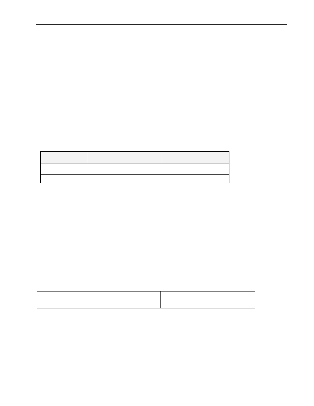
MTBF
MTBF
Product
Voasis™ Control
Unit
Voasis™ Access Pod
(Hours) MTBF (Years) Temperature
262,800 30 50degC||122degF
262,800 30 50degC||122degF
Preface Material
About This Guide
This guide provides essential product functionality with all the information necessary to proper
installation and configuration of the Voasis™ UMTS/DCS/PCS system.
Revision History
The revision history for this document is shown in Table-1.
Table 1: Revision history
P/N and REV Date Description
709C003501 REV A00 May 2009 First edition
Voasis™ UMTS/DCS/PCS Installation and Configuration Manual V
Page 6

Preface Material
List of Acronyms
Term Meaning
DCS Digital Cellular System
PCS Personal Communication Service
PoE Power Over Ethernet
PSE Power Sourcing Equipment
SME Small / Medium Enterprise
STP Shielded Twisted Pair
UMTS Universal Mobile Telecommunication Service
UTP Unshielded Twisted Pair
VAP Voasis Access Pod
VCU Voasis Control Unit
VI Voasis™ UMTS/DCS/PCS Installation and Configuration Manual
Page 7

Table of Contents
Preface Material .........................................................................................................................III
1 Overview...............................................................................................................................1
1.1 System Architecture..................................................................................................................2
1.2 System Elements ...................................................................................................................... 2
1.2.1 Voasis™ Control Unit (VCU)..............................................................................................2
1.2.1.1 VCU Front Panel ..................................................................................................3
1.2.1.2 VCU Rear Panel ...................................................................................................4
1.2.2 Voasis™ Access Pod (VAP)................................................................................................4
1.2.3 System Management........................................................................................................5
2 Installation Workflow...........................................................................................................6
3 Infrastructure Requirements and Layout Planning ..........................................................7
3.1 General information on Location and Connections........................................................................7
3.2 Infrastructure Requirements ......................................................................................................8
3.3 Coverage and Installation Planning.............................................................................................8
3.3.1 Types of Environment......................................................................................................9
3.3.1.1 Open environment ...............................................................................................9
3.3.1.2 Standard Environment..........................................................................................9
3.3.1.3 Dense Environment:.............................................................................................9
3.3.1.4 Combination of Environments ............................................................................. 10
3.4 Planning VAP Layout ............................................................................................................... 10
3.4.1 Interference Factors....................................................................................................... 10
3.4.2 Mapping Locations......................................................................................................... 10
3.4.3 Installation Plan Example ............................................................................................... 11
4 VCU Installation and Configuration..................................................................................13
4.1 VCU Installation...................................................................................................................... 13
4.2 VCU IP Configuration............................................................................................................... 14
4.2.1 Configuring Your Computer to the Same Subnet as the VCU.............................................. 14
4.2.2 Configuring the VCU IP Address...................................................................................... 15
4.2.3 Lost the VCU IP Address?............................................................................................... 16
4.2.3.1 Remotely determining the VCUs IP address.......................................................... 17
Voasis™ UMTS/DCS/PCS Installation and Configuration Manual VII
Page 8

Contents
4.2.3.2 Locally Determining the VCU’s IP Address ............................................................ 17
4.3 Voasis™ Control SNMP Configuration........................................................................................ 18
4.3.1 Installing the Lantronix DeviceInstaller Application............................................................18
4.3.2 Opening a Telnet Session to a Unit.................................................................................. 19
4.3.3 Setting SNMP Parameters............................................................................................... 22
4.4 Voasis™ Control Unit Configuration...........................................................................................23
4.5 What Next?............................................................................................................................ 25
5 Voasis™ Access Pod (VAP) Installation and Monitoring...............................................26
5.1 VAP Installation ...................................................................................................................... 26
5.2 Placing the VAPs..................................................................................................................... 27
5.2.1 Desktop mount.............................................................................................................. 27
5.2.2 Wall Mount.................................................................................................................... 28
5.2.3 Jack Mount....................................................................................................................28
5.3 Verifying Coverage.................................................................................................................. 28
5.4 Configuring the VAPs............................................................................................................... 29
5.5 Verifying System Connections and Monitoring............................................................................ 30
5.6 Verifying Complete Coverage ................................................................................................... 31
6 Navigating the Management Application.........................................................................32
6.1 Connecting to the Management Application............................................................................... 32
6.2 Set or Change the Management Application Password................................................................ 33
6.3 VCU Configuration Window...................................................................................................... 34
6.3.1 General Tab.................................................................................................................. 35
6.3.2 RF Config Tab ............................................................................................................... 36
6.3.3 Alarms Tab....................................................................................................................37
6.4 Monitor Screen - Active Events.................................................................................................38
6.5 VAP RF Configuration.............................................................................................................. 39
6.6 VAP Alarms ............................................................................................................................ 40
6.7 Traps..................................................................................................................................... 41
VIII Voasis™ UMTS/DCS/PCS Installation and Configuration Manual
Page 9
1 Overview
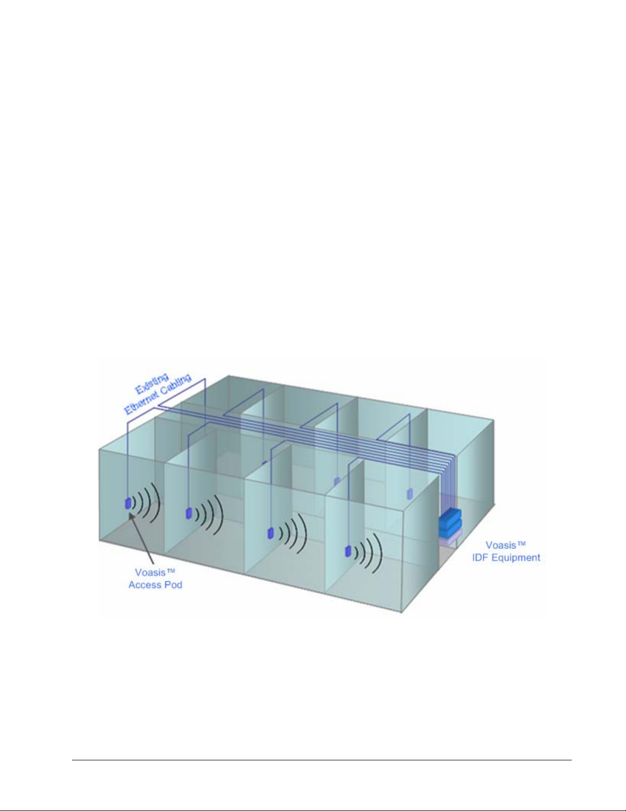
MobileAccess Voasis™ wireless coverage solution provides low-cost, self-installable
UMTS/PCS/DCS in-building coverage for small and medium size enterprises (SMEs), multi-tenant
buildings, and multi dwelling units.
The solution distributes the UMTS/PCS/DCS signal from the service provider’s equipment to
antennas (VAPs) installed throughout a single floor via the existing CAT-5/6 cabling
infrastructure.
The VAPs (Voasis™ Access Pods) plug into standard (spare) Ethernet connection points on the
floor and are powered via PoE technology. All the VAPs on each floor are managed via a VCU
(Voasis™ Control Unit) located in the communication shaft. The VCU interfaces to the provider’s
equipment and provides secure, central management to the VAPs.
This plug-and play UMTS/PCS/DCS coverage solution can be easily and quickly installed by the
SME – no RF specialist required.
The following figure illustrates a typical Voasis™ installation.
Voasis™ UMTS/DCS/PCS Installation and Configuration Manual
1
Page 10
Overview
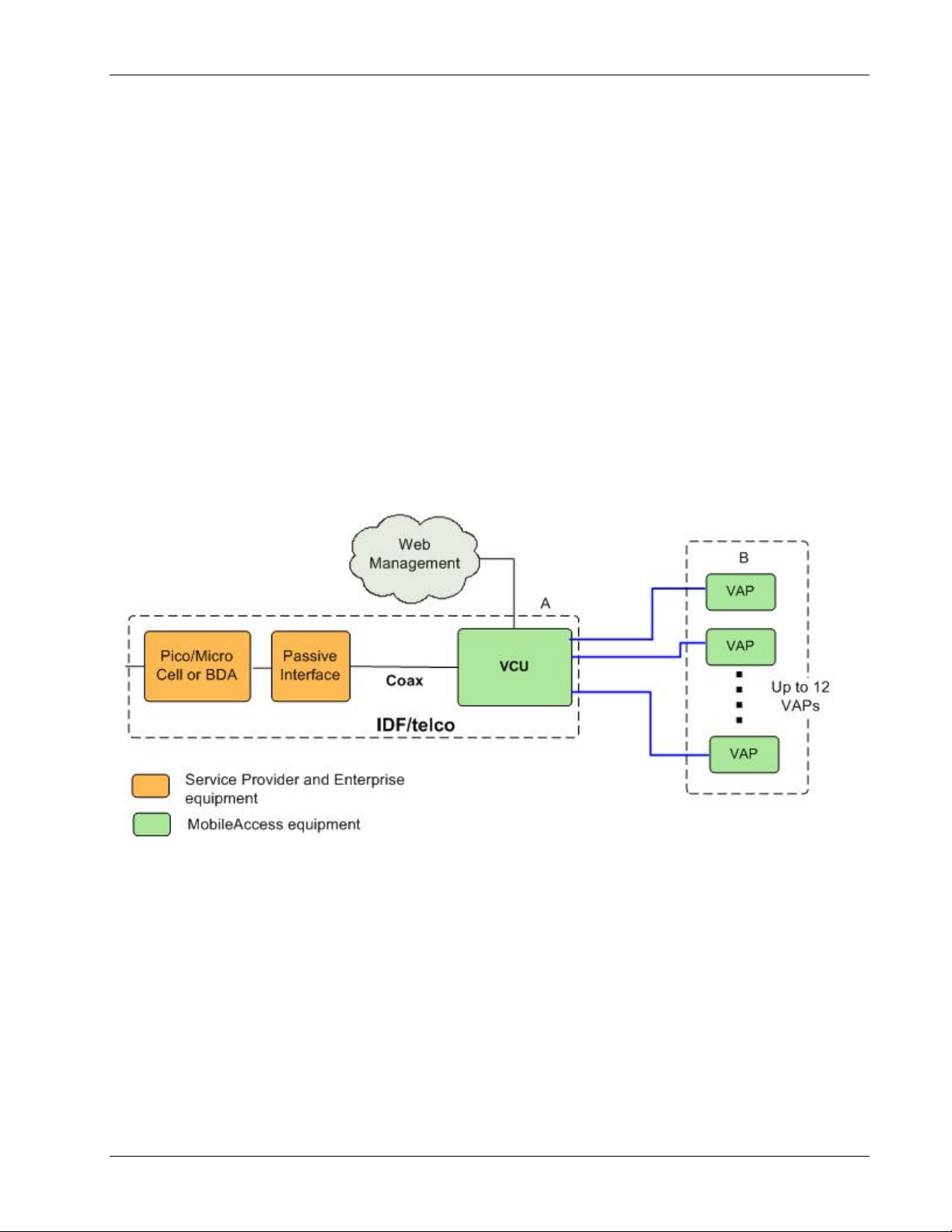
1.1 System Architecture
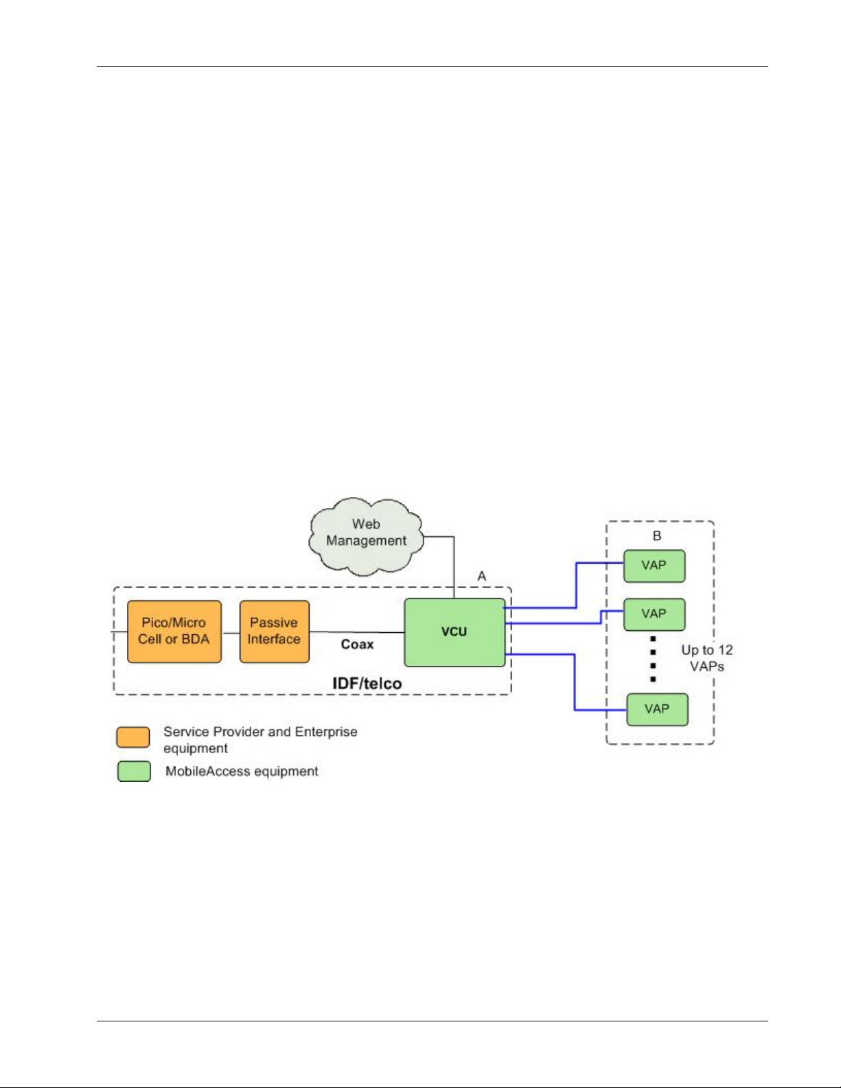
Main elements - The Voasis™ solution is based on the following main elements installed on
each floor
•
VCU (Voasis™ Control Unit)
interfaces to the service provider’s RF source and provides secure, central management to the
VAPs.
VAPs (Voasis™ Access Pods)
•
locations on the floor to provide maximum coverage. VAPs provide RF coverage via integrated,
internal antennas. VAPs equipped with interface for external antennas are available for special
coverage requirements.
The following figure illustrates the Voasis™ solution.
:
– This unit is installed in the communication closet (IDF).
– These are pluggable antennas distributed at strategic
Up to 12 VAPs can be connected to a single VCU using LAN cables (CAT-5E or higher).
Figure
1-1. Voasis™ Basic Architecture
1.2 System Elements
This chapter describes the Voasis™ system basic elements: VCU and VAPs.
1.2.1 Voasis™ Control Unit (VCU)
The VCU interfaces to the cellular service provider equipment (picocell/BDA) and to the VAPs (via
CAT-5/6).
The RF and management connections are located on the front panel; the power connection is on
the rear panel.
2 Voasis™ UMTS/DCS/PCS Installation and Configuration Manual
Page 11
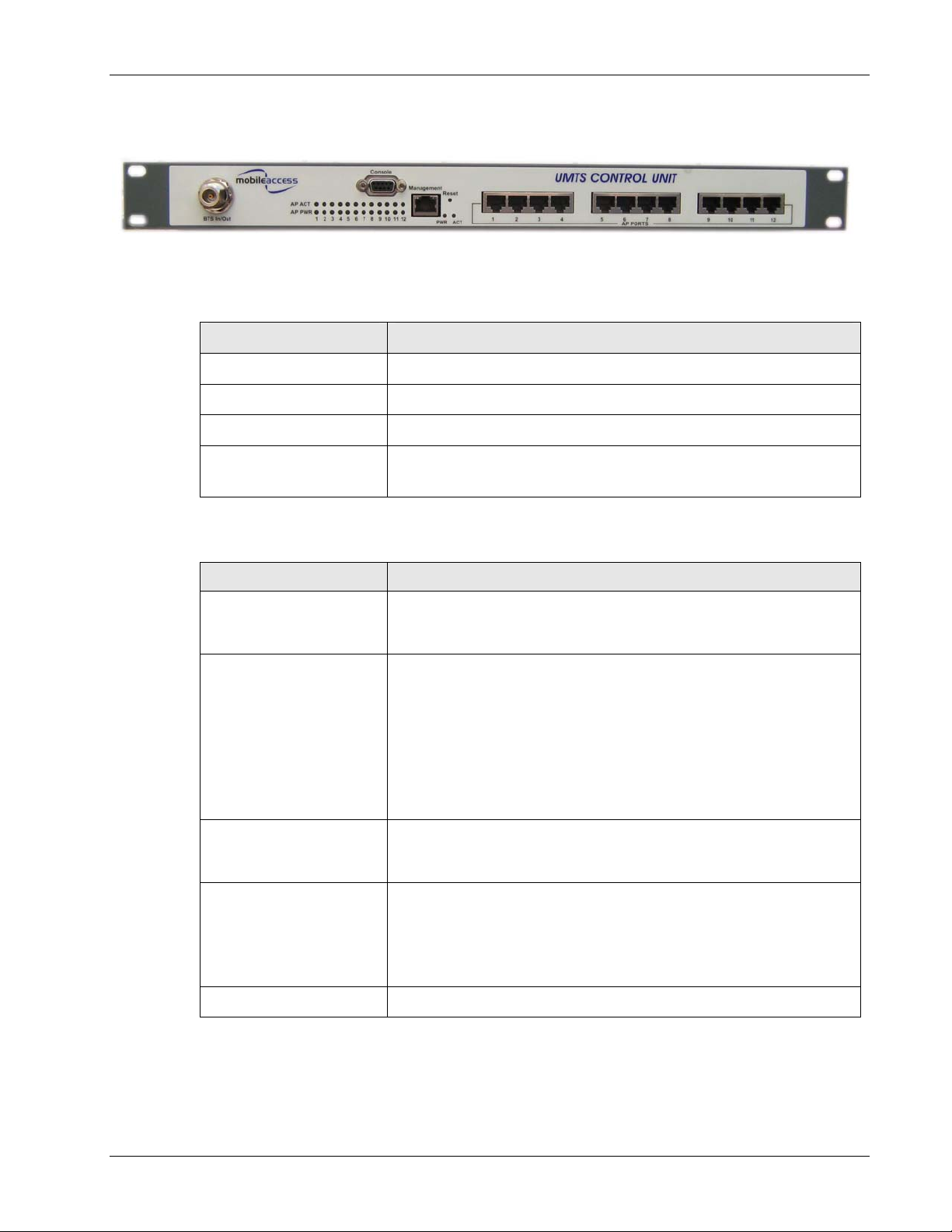
1.2.1.1 VCU Front Panel
Overview
Figure
Table
Table
1-2. VCU Front Panel
1-1: VCU Ports Description
Ports Description
BTS In/Out RF connections to the service provider equipment
Console RS232 local management connection
Management RJ45 WEB management connection
(V)AP Ports 1-4, 5-8,
9-12
1-2: VCU LEDs Description
LED Description
System PWR
System ACT
AP PWR
AP ACT
Reset Reset
VAP port connections. RJ-45 connection to VAP through the LAN
infrastructure
VCU power LED (Green):
Green - Power to VCU is OK
Off - No power is received by the VCU
System activity LED (Green):
Slow Blink – Normal operation
Fast Blink – user activated ‘Control Unit Identify’ on this VCU.
Solid Green - one of the following:
- Control Unit is initializing
- No RF signal from BTS
- Service is off
Off - VCU is faulty.
Access Pod Power indication (Green)
Green – power supplied to corresponding port.
Off – no power (to corresponding VAP) supplied to port.
Status of corresponding VAP (Green).
Slow Blink - associated VAP is initializing
Fast Blink – user activated ‘Access Pod Identify’ on this AP.
Solid - associated VAP normal operation.
Off – associated Access Pod is faulty or disconnected.
Voasis™ UMTS/DCS/PCS Installation and Configuration Manual 3
Page 12

Overview
1.2.1.2 VCU Rear Panel
The VCU DC power connection is located at the VCU rear panel.
Figure
1-3. VCU Rear Panel
1.2.2 Voasis™ Access Pod (VAP)
Each VAP functions as antenna – transmitting and receiving RF service signals. Every VAP is
connected to an RJ-45 jack via the RJ45 connector on the VAP underside.
Note: The VAP is connected to spare Ethernet jacks that are not already in use in the Ethernet
network.
The VAP can be mounted/hanged on the wall or placed on a flat surface (such as a desk).
The following figure shows the desktop VAP and the underside view with the CAT-5/6 patch-cord
cable.
90-264V AC, 47-63 Hz
250W (fully loaded)
Figure
1-4. Voasis™ Access Pod
VAP LED Indicators:
Table 1-3: VAP LEDs
LED Description
PWR Solid Green - Power supplied to VAP
Off - No power supplied to VAP
ACT
4 Voasis™ UMTS/DCS/PCS Installation and Configuration Manual
Status of VAP (Blue)
Solid – power supplied to VAP, normal operation.
Fast Blink – user activated ‘Access Pod Identify’ on this AP.
Slow Blink – power supplied to VAP, unit initializing.
Off – power not supplied to Access Pod or Access Pod is faulty.
Page 13

1.2.3 System Management
• The VCU is connected to the IP backbone through the management port.
• The VCU and corresponding VAP units are managed through a remote connection to the VCU
via any standard WEB browser.
Overview
Voasis™ UMTS/DCS/PCS Installation and Configuration Manual 5
Page 14
Installation Workflow
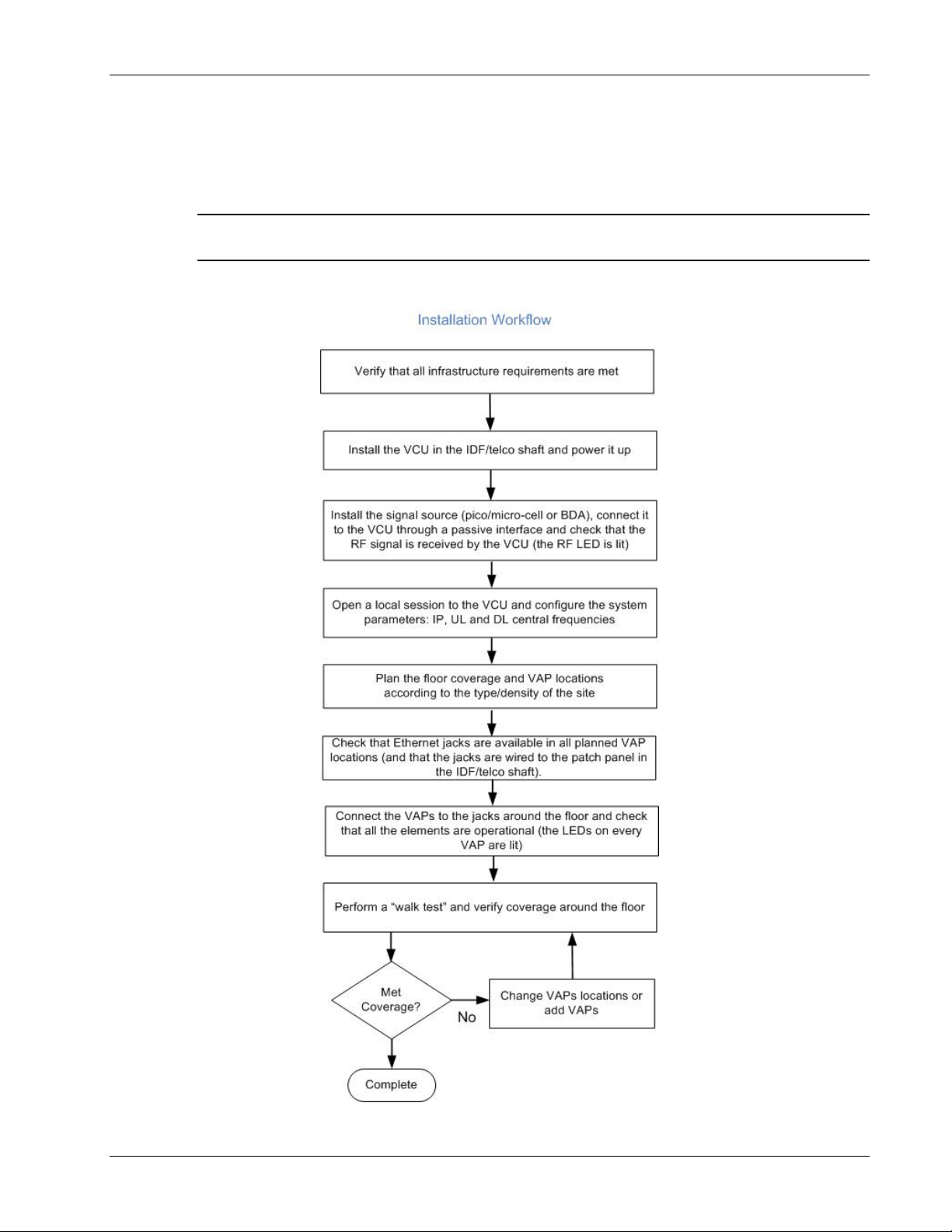
2 Installation Workflow
Note: It is recommended to first install the Voasis™ system, verify connectivity and only then
installing the signal source.
The following figure summarizes the main steps of the installation procedure:
6 Voasis™ UMTS/DCS/PCS Installation and Configuration Manual
Page 15
Infrastructure Requirements and Layout Planning
3 Infrastructure Requirements and Layout
Planning
3.1 General information on Location and Connections
• The Service provider’s RF equipment (Pico-cell, Femto-cell, BDA, etc.) is connected to the VCU
through a passive interface.
• The VCU is installed at the IDF/telco cabinet of the covered floor and connected to the cabling
patch panel.
• The RF signal is overlaid from the VCU to the VAPs (up to 12) onto the existing (
) Ethernet CAT-5/6 cabling infrastructure.
use
• The VAPs are spread over the floor for maximum coverage and can be mounted in various
ways – directly on the wall or on the desktop (or over the existing RJ-45 jack).
• No special power connections are required as the VAPs are power fed from the VCU using PoE
(power over Ethernet) technology.
but not in
Figure
3-1. Voasis™ Basic Architecture
Voasis™ UMTS/DCS/PCS Installation and Configuration Manual 7
Page 16

Infrastructure Requirements and Layout Planning
3.2 Infrastructure Requirements
There is no need to deploy new infrastructure for connecting the VAPs to the VCU – you can
utilize the CAT-5E cables and Ethernet jacks that were prepared for your LAN (but are not
currently connected to an Ethernet switch), assuming they meet the following minimum
requirements:
1. IDF/telco closet space for one VCU (48.3 x 30 x 4.44 cm).
2. 110/220AC 60Hz (250W) power for the VCU (IDF/telco closet).
3. Ethernet cabling to VAPs:
• Minimum cabling - Category 5E cabling or better (Unshielded or Shielded Twisted Pair
(UTP/STP)).
• For CAT-5 cabling - 24 AWG minimum diameter
• CAT-5/6 cable run lengths - 100m (300ft) maximum
4. Cable Connections:
• 1x N-type Female, 50 ohm interfaces to carrier equipment.
• 13 RJ-45 connectors for 12 Voasis™ Access Pods (one for management)
5. RG6 distribution cables (if needed) - 100m (300ft) total length maximum.
3.3 Coverage and Installation Planning
The maximal coverage area of each VAP is affected by the density and type of environment to
be covered. Therefore, it is recommended to plan the
achieve complete coverage of the floor.
The
exact
location is selected according to the feasibility in the wanted VAP installation location,
where each unit may be mounted on a wall or placed on a desk.
This section provides information on coverage criteria in various types of environments (Open,
Standard, Dense and Merged) and provides rules-of-thumb for various installations of the VAPs.
Note: Section
environment. It is recommended to review this example after reading this section.
3.4 provides a detailed example of installation planning in various types of
ideal
location of each VAP in order to
8 Voasis™ UMTS/DCS/PCS Installation and Configuration Manual
Page 17

3.3.1 Types of Environment
This section describes the different types of installation environments and provides guidelines for
best coverage of each type of space.
3.3.1.1 Open environment
An environment with minimum of obstacles (such as walls). This type of space can be a large
conference or meeting room, cubical areas, lobby or atrium areas.
Table
3-1: Open Environment Installation Distances
Signal Propagation from VAP 60 feet (20 m)
Recommend spacing between VAPs 120 feet (40 m)
Recommended maximum distance of
VAPs from outer walls
Infrastructure Requirements and Layout Planning
60 feet (20 m)
3.3.1.2 Standard Environment
A traditional office environment with offices, hallways and scattered cubicles.
Table
3-2: Standard Environment Installation Distances
Signal Propagation from VAP 40 feet (12 m)
Recommended Spacing between VAPs 80 feet (25 m)
Recommended Maximum distance of
VAPs from outer walls
3.3.1.3 Dense Environment:
A dense environment has a lot of walls, offices, equipment, tall file cabinets, bookshelves and
other items that would potentially impact the wireless signal.
Examples for this kind of environment are dense offices, hospitals and manufacturing spaces.
Table
3-3: Standard Environment Installation Distances
Signal Propagation from VAP 30 feet (10 m)
Recommended Spacing between VAPs 60 feet (20 m)
Recommended Maximum distance of
VAPs from outer walls
40 feet (12 m)
30 feet (10 m)
Voasis™ UMTS/DCS/PCS Installation and Configuration Manual 9
Page 18

Infrastructure Requirements and Layout Planning
3.3.1.4 Combination of Environments
In areas with combinations of environments of various densities, place the VAPs on the border
between the different types of areas – closer to the denser area.
For example in a cubical area with the outside wall having offices, simply locate the VAPs a little
closer to the outside offices
the floor plan map in section
To ensure a maximal coverage, VAPs can be moved or added. If a coverage gap is detected, the
VAPs can be re-placed until the coverage gaps are filled.
to provide coverage through the office walls. (See VAPs 11 and 13 in
3.4.3.)
3.4 Planning VAP Layout
The following section describes the steps of planning the VAPs along the covered floor. At the
End of this section an example of a planning map is attached.
Note: It is highly recommended to use a floor plan when planning the VAPs locations.
3.4.1 Interference Factors
It is important to note the type of factors that can severely impact RF coverage which should be
avoided:
• Metallic structures like elevators, tall file cabinets and some moveable metallic partitions
severely degrade RF signal and all efforts should be made to locate VAPs in front of or above
metallic objects (desks, filing cabinets) to allow the signal to propagate.
• Wall materials such as concrete, tile and cinderblock along with bathroom fixtures typically
have fairly high signal attenuation and should be considered dense spaces.
• Some glass (typically exterior or mirrored) has metallic coatings on it which can affect RF
coverage however that is typically not encountered inside a building.
3.4.2 Mapping Locations
To map the VAP Locations
1. Map out the available locations: mark all the CAT-5/6 drops that are not in use locations on
the floor plan map.
TIP: It may be handy to use the size and number of the ceiling tiles to measure distances.
2. Using the floor plan and the VAPs coverage guidelines (as given in 3.4.3) mark
approximately where you would like to place each VAP in the facility.
If you are not sure of how dense should the VAPs be laid out, you can either choose a more
dense installation or a less dense one and add more VAPs if needed after installation.
10 Voasis™ UMTS/DCS/PCS Installation and Configuration Manual
Page 19

3. After choosing all the jacks to be used, make sure that all the right jacks are connected to
the patch panel at the IDF/telco shaft.
4. It is also recommended to check the area in which the VAPs are about to be installed and
make sure that the installation is feasible.
5. Plan the IDF/telco shaft to hold the RF equipment (pico-cell/micro-cell or BDA) and the VCU.
3.4.3 Installation Plan Example
The Following figure shows a floor plan map with all needed marks:
Infrastructure Requirements and Layout Planning
Figure
3-2. Floor Plan Example
Notes:
• The red VAP coverage circles are approximately 30, 40 and 60 foot radius for the small,
medium and large circles respectively (drew according to the guidelines given in section
• VAP 3 is surrounded by dense objects, the bathroom and stairwell which would reduce
coverage in that area by the other VAPs.
• VAP 5 is an example of a unit that provides good coverage down the hallways.
Voasis™ UMTS/DCS/PCS Installation and Configuration Manual 11
0).
Page 20

Infrastructure Requirements and Layout Planning
• VAPs 11 and 13 are placed closer to the offices to cover them well but on the open side will
actually cover a much greater area which is why the coverage is larger and shown here more
as an oval than a circle.
• The area between VAPs 7 and 14 outside the bathrooms would probably be the lowest
coverage spot in the building because of the bathrooms and stairwell on either side of that
area. If after the system installed, this area is still a little low on coverage, a VAP can be
added, but it may also be covered by VAP 14.
Note: The plan can be modified at any time by moving the units around or by adding units.
The following figure depicts an actual measured quantified coverage of a floor aria planed
according to the above rules
Figure
3-3. Distributed VAPs propagation, 12dBm output power @ 1.8GHz.
12 Voasis™ UMTS/DCS/PCS Installation and Configuration Manual
Page 21

VCU Installation and Configuration
4 VCU Installation and Configuration
This section describes the installation and configuration procedures of the Voasis™ Control Unit
(VCU). These should be performed only after planning the floor coverage and installation
locations as described in section
The Voasis™ Single Band Solution VCU kit includes:
Table
4-1: VCU Kit
Description UNIT and P/N
Voasis™
Control Unit
(VCU) kit
3.3.
Power cord
Voasis™ SW
CD
Local
configuration
cable
(crossed RJ45 cable)
4.1 VCU Installation
1. Install the Voasis™ Control Unit (VCU) in the IDF/Telco closet corresponding to the floor to
be covered. The VCU can be installed in the rack or on the wall using the optional wall
mount bracket at the IDF closet along with the provider’s signal source.
P/N: 255880010
P/N: 705B000101
2. Connect the VCU to the patch-panel that feeds the existing structured CAT-5/6 cabling
system.
3. Connect (or request the service provider’s service personnel to connect) the provider’s signal
source (pico-cell/micro-cell or BDA) to the RF ports on the VCU, through a passive interface.
4. Apply power to the VCU.
Voasis™ UMTS/DCS/PCS Installation and Configuration Manual 13
Page 22

VCU Installation and Configuration
5. Power on the signal source and note that the VCU LED is lit. It indicates that RF inputs are
being received.
4.2 VCU IP Configuration
In order to enable remote management it is required to change the VCU static IP address. This
is done via a local connection from a computer (i.e. laptop) to the VCU, using a standard Web
Browser such as Explorer.
The VCU default IP address is 192.168.1.1., where it is required to pre-configure the computer
to the same Subnet as the default VCU IP addresses.
4.2.1 Configuring Your Computer to the Same Subnet as the VCU
This procedure is required in order to locally connect to the VCU.
Note: The procedure may vary, depending on your computer’s Operating System.
To configure the computer’s network parameters
1. Click the Start menu and choose Control Panel.
2. In the Control Panel, click Network and Internet Connections.
3. Click Network Connections and then double-click Local Area Connection.
The Local Area Connections Properties dialog appears with the General tab displayed by
default.
4. In the Items list, select Internet Protocol (TCP*IP) and click Properties.
14 Voasis™ UMTS/DCS/PCS Installation and Configuration Manual
Page 23

The Internet Protocol (TCP/IP) Properties dialog appears.
• Assign an IP
192.168.1.9).
• Set the Subnet mask as shown: 255.255.255.0
address within the following range: 192.168.1.2 to 192.168.1.250. (i.e.
VCU Installation and Configuration
5. Click OK.
6. Configure the VCU IP address according to the following sections.
4.2.2 Configuring the VCU IP Address
To configure the VCU static IP parameters
1. Connect a laptop to the VCU Management port via an Ethernet cross-cable.
Note: Some computers may not require a cross-cable since the option is automatically builtin. In this case, you may use a standard Ethernet cable.
2. Open a Web browser and in the address bar, type the default IP address (192.168.1.1).
Note: The laptop must be pre-configured to the same Subnet as the default VCU IP address.
Voasis™ UMTS/DCS/PCS Installation and Configuration Manual 15
Page 24

VCU Installation and Configuration
3. On the invoked application window, choose the Configuration main tab and click General.
4. Define the IP Address parameters according to instructions given by your network manager:
• IP Address
• Subnet Mask
• Default Gateway
Note: After IP address configuration, the VCU can be accessed remotely via Ethernet. To
continue the configuration session locally, configure the laptop to the same Subnet as
configured for the VCU.
4.2.3 Lost the VCU IP Address?
Note: It is recommended to record the IP address and corresponding MAC address of each unit.
If you lost your VCU IP address:
1. Install the Lantronix DeviceInstaller (see 4.3.1).
2. Do you know the unit’s MAC address?
• If the unit MAC address is known – follow the instructions in section
• If the unit MAC address is NOT known – follow the instructions in section
4.2.3.1.
4.2.3.2.
16 Voasis™ UMTS/DCS/PCS Installation and Configuration Manual
Page 25

4.2.3.1 Remotely determining the VCUs IP address
Use this method if the IP address is known.
If the VCU MAC address is known
1. Launch the Lantronix DeviceInstaller application.
VCU Installation and Configuration
2. Click the Search icon
Note: the procedure may take several seconds for the list of devices to be displayed in the
device list.
3. Locate the unit IP Address according to its Hardware Address (MAC address).
in the toolbar to discover all connected VCUs.
4.2.3.2 Locally Determining the VCU’s IP Address
Use this method if the VCU’s IP address is NOT known.
If the VCU MAC address is NOT known
1. Connect to the unit locally and open a Telnet session to the corresponding unit using the
Lantronix DeviceInstaller as explained in section
4.3.2.
IP address
MAC address
Note: Some computers may not require a cross-cable since the option is automatically builtin. In this case, you may use a standard Ethernet cable.
2. After performing the discovery action, the unit information will be displayed in the
application main menu, including the IP address.
Voasis™ UMTS/DCS/PCS Installation and Configuration Manual 17
Ethernet cross cable
IP address
MAC address
Page 26

VCU Installation and Configuration
4.3 VCU SNMP Configuration
In order to enable remote management it is required to configure the VCU SNMP parameters.
The VCU SNMP configuration is performed using the Lantronix DeviceInstaller application –
an external application available on your Setup CD.
4.3.1 Installing the Lantronix DeviceInstaller Application
This section describes how to install the Lantronix Device Installer application.
Note: This external application is provided with your Setup CD and can be downloaded from the
Lantronix web (www.lantronix.com) site at any time free of charge.
To install the Lantronix DeviceInstaller
1. Insert the supplied Setup CD in your computer drive.
2. Run the file Setup.exe and follow the displayed prompts.
3. From the Start menu, select Lantronix, DeviceInstaller.
• If multiple Network Adapters are installed in your system, you may be prompted with
the following dialog (otherwise, the Lantronix main window appears).
• (If prompted), click Yes. A dialog listing the currently available network adapter cards
appears. For example
• Select your network connection and click OK. The Lantronix Main window appears.
18 Voasis™ UMTS/DCS/PCS Installation and Configuration Manual
Page 27

4.3.2 Opening a Telnet Session to a Unit
This section describes how to open a Telnet session to a VCU using the Lantronix Device
Installer application.
To open a telnet session to a unit
VCU Installation and Configuration
1. Verify that the laptop IP is set to the same subnet as the static IP address assigned to the
Controller (e.g. 192.168.1.2), as performed in section
2. Use an Ethernet cross-cable to connect your computer (running the DeviceInstaller) to the
VCU Ethernet port.
the cross-cable function is built-in).
3. Launch the DeviceInstaller application on your computer:
• Click the Start menu, select Lantronix and choose DeviceInstller or
• Click the application icon on your desktop (if you’ve created a shortcut)
The DeviceInstaller main window appears.
(Some computers may not require a cross-cable for a connection since
Ethernet cross cable
4.2.1.
Voasis™ UMTS/DCS/PCS Installation and Configuration Manual 19
Page 28

VCU Installation and Configuration
4. Click the Search icon
in the toolbar to discover the connected VCU and list it in the
window.
Note: If you are connected to the network, all the VCUs in the network will be discovered
and the procedure may take several seconds for the list of devices to be displayed in the
device list.
IP address
MAC address
The right pane will show the currently connected VCU(s) according to its IP Address and
MAC Address (Hardware Address), in addition to other information.
In the left pane, the discovered units are listed under the corresponding Xport version (your
display will probably show a single Xport version and the unit(s) will be listed under that
item).
5. In the left pane, double-click on the IP address to which a Telnet session is to be opened.
20 Voasis™ UMTS/DCS/PCS Installation and Configuration Manual
Page 29

VCU Installation and Configuration
Three tabs appear in the right pane:
6. Select the Telnet Configuration tab and click the Connect button. A Telnet session is
opened to the relevant controller.
7. Press Enter to go into Setup Mode.
The Change Setup options menu appears at the bottom of the pane.
8. Refer to the following section for instructions on setting the SNMP parameters.
Voasis™ UMTS/DCS/PCS Installation and Configuration Manual 21
Page 30

VCU Installation and Configuration
4.3.3 Setting SNMP Parameters
After opening a telnet session to the corresponding unit using the Lantronix DeviceInstaller (as
explained in section
1. In the Change Setup menu enter 3 (SNMP Configuration).
Change Setup:
0 Server configuration
1 Channel 1 configuration
3 SNMP configuration
8 exit without save
9 save and exit Your choice 3
2. Set the SNMP Read and Write community names and the SNMP traps destination addresses
(up to three addresses can be defined).
SNMP community name for read (): public
SNMP community name for write (): private
Enter IP addresses for SNMP traps:
1: (000) 192.(000) 168.(000) 10.(000) 22
2: (000) .(000) .(000) .(000)
3: (000) .(000) .(000) .(000)
4.3.2):
3. Press Enter to run through the rest of the parameters. When the Setup Menu is displayed
again, select 9 – Save and Exit
22 Voasis™ UMTS/DCS/PCS Installation and Configuration Manual
Page 31

4.4 Voasis™ Control Unit Configuration
Note: After the initial configuration, the VCU can be accessed remotely via the Ethernet.
1. Open a web browser and type in the address bar the default IP address. (192.168.1.1)
2. On the invoked application window, choose the Configuration main tab, click the General
tab at the bottom of the pane.
VCU Installation and Configuration
Name
IP Address
3. Define the
4. Click the RF Config tab (at the bottom of the Configuration pane).
name
and click Apply:
Voasis™ UMTS/DCS/PCS Installation and Configuration Manual 23
Page 32

VCU Installation and Configuration
Service DL CF
Service DL CF
Max expected
power of BTS
5. Verify that the Service Type is correct according to the system installed: UMTS, PCS or
DCS.
6. Define the following parameters:
• Max expected in – maximum power of Base Station
• Service DL CF – Base Station downlink Central Frequency (the corresponding Uplink
frequency is automatically assigned).
The DL CF should match the service range as follows:
• UTMS : 2110-2170 MHz
• DCS: 1805-1880 MHz
• PCS: 1930-1990 MHz
Note: If the frequency that was typed is not in range, an error appears in yellow above the
VAPs links buttons.
The UL CF will be calculated and set by the system automatically.
Notes:
1. These parameters are service dependent and can be obtained from you service provider.
2. The remaining parameters are predefined to their default values. (Service Bandwidth is
set to 20MHz).
3. Any updating of the service definition: DL CF or BW is sent to all connected VAPs.
24 Voasis™ UMTS/DCS/PCS Installation and Configuration Manual
Page 33

VCU Installation and Configuration
7. Click the Alarms tab (at the bottom of the Configuration pane). Verify that all the alarms
are GREEN. Refer to the alarm descriptions in the table following the figure below.
VCU Alarms Description
Alarms Description
DL RF Pwr Low RED - DL RF Power is 20dB less than maximum expected power
DL RF Pwr High RED - the input power exceeds the maximum expected power defined
Overpower
Protection
VCU Faulty RED - VCU fault. Remove and re-apply power to VCU. If problem
Overall Status Status of highest fault.
4.5 What Next?
Do not disconnect the WEB management application from the VCU; you will be using it to verify
the connections after all the VAPs are placed in their locations.
defined by the user. i.e. if user defined a maximum power of 30 dBm,
the DL RF Pwr Low will be RED if the measured power is 10dBm or
less.
by the user by 3 dB or more.
N/A
persists, replace VCU.
Voasis™ UMTS/DCS/PCS Installation and Configuration Manual 25
Page 34

Voasis™ Access Pod (VAP) Installation and Monitoring
B
5 Voasis™ Access Pod (VAP) Installation
and Monitoring
The VAPs installation procedure consists of connecting each VAP to the Ethernet jack in the
appropriate location to provide optimal coverage.
Note that the VAPs are connected to spare jacks that are not currently in use.
The VAPs are auto-discovered by the VCU and can be monitored via remote connection to the
VCU.
5.1 VAP Installation
The Voasis™ Single Band Solution VAP kit includes:
Table
5-1: VAP Kit
A) Voasis™ Access Pod
B) Wall-mount adaptor
C) Desk-mount adaptor
D) RJ-45 jumper cable
E) 4 screws (P/N 265900080):
• 2 – for securing the adaptor to the Access Pod.
• 2
- for securing the wall-mount adaptor to the wall
(for “anti-theft” installation)
Note: VAPs come with two mounting options: desktop and wall mount .
(P/N: 264A031801)
(P/N: 264A031701)
(P/N: 705A016501)
A
C
D
26 Voasis™ UMTS/DCS/PCS Installation and Configuration Manual
Page 35

r
A
A
5.2 Placing the VAPs
It is preferable to place the VAPs on top of desks, cube walls, filing cabinets or higher on walls.
Note: Hiding a VAP under a desk or low down in a corner decreases the effective coverage of
the VAP and therefore requires a higher number of VAPs to cover a given area.
When placing the VAPs, take the following into consideration:
• Wherever possible, place the units in an open area.
• Availability of CAT-5/6 infrastructure - the VAPs are connected to the SPARE (not in use)
jacks).
• Aesthetics of the VAP location
• The VAPs plug into standard (RJ-45) Ethernet connection jacks.
5.2.1 Desktop mount
Voasis™ Access Pod (VAP) Installation and Monitoring
• Secure the Desk-mount adaptor to the Voasis™ Access Pod using the supplied s c rews.
• Connect the RJ-45 jumper cable (CAT-5/6) to the VAP.
• Place the VAP on a flat surface according to the planned location.
• Plug the other side of the cable into adjacent standard (RJ-45) Ethernet connection jack.
(the adaptor screws and cable are included in the VAP kit).
ssembly
+ =
ccess POD
Desktop adapto
Ext. Antenna
RJ-45
to VCU
RJ-45 to
computer
Ext. Antenna
Voasis™ UMTS/DCS/PCS Installation and Configuration Manual 27
Page 36

Voasis™ Access Pod (VAP) Installation and Monitoring
r
A
A
y
5.2.2 Wall Mount
• Assemble the wall-mount adaptor to the VAP (The adaptor screws, wall mount screws, sticky
tape and cable are included in the VAP kit as described in
• Connect the RJ-45 jumper cable (CAT-5/6) to the VAP
• Attach the VAP to the wall according to the planed location using supplied screws (for “anti-
theft” installation) or the double sided sticky tape for the wall-mount adaptor (for “plug-andplay” installation)
• Plug the other side of the cable into adjacent standard (RJ-45) Ethernet connection jack.
• Verify the VAP receives power and sync up to the VCU via the LEDs on the unit.
Table 5-1: VAP Kit)
+ =
ccess POD
5.2.3 Jack Mount
The VAP can also be fitted onto an RJ-45 jack. This requires separ ately ordered brackets that are
customized according to customer site requirements.
5.3 Verifying Coverage
Verify coverage in the areas, adding and moving VAPs for optimal coverage according to the
principles described in
3.3.
Wallmount adapto
ssembl
28 Voasis™ UMTS/DCS/PCS Installation and Configuration Manual
Page 37

5.4 Configuring the VAPs
To configure the VAPs parameters use the Voasis™ configuration application.
Voasis™ Access Pod (VAP) Installation and Monitoring
Note: See chapter
1. Open the Voasis™ configuration application (web interface). In the invoked Login window
select your User Name and type in your password:
See section
2. For EACH VAP: (1) Choose the General sub tab, (2) Choose the VAP to be configured, (3) In
the work area enter the VAP name (i.e. Conference Room, Lobby, etc.)
6 for full explanation about navigating the Voasis™ configuration application.
6.1 for Usernames and Passwords list.
After all the VAPs names are set, verify the system connections by following the next section
(
5.5)
2. Select the
General tab
Voasis™ UMTS/DCS/PCS Installation and Configuration Manual 29
1. Select the VAP
to be configured
3. Set the VAP
name
Page 38

Voasis™ Access Pod (VAP) Installation and Monitoring
5.5 Verifying System Connections and Monitoring
1. Select the Monitor tab. The following window appears. The window is divided into three
areas:
• Control Unit Configuration – shows the user defined VCU name, IP address and the HW
and SW versions. The IP address can be modified via the Configuration tab.
• Device Summary – summarizes the total number of current Alerts (RED) and previous
alerts (GREEN).
• Link Summary – shows the highest level alert on each VAP. Click the relevant button to
access detailed monitoring screen of relevant VAP.
• Active Events – system events.
Active events
Link Summary – click button to
access monitoring pane of
relevant POD
Note: Any updating of the service definition: DL CF, UL CF is sent to all connected VAPs.
2. Verify the following:
• In the Device Summary area – that there are NO RED alarms. If an alarm is displayed
in the Apod area, click the relevant Link Summary button (representing the
corresponding VAP) to analyze the alarms of the corresponding VAP according to section
6.6.
• In the Link Summary area, all buttons are GREEN.
• In the Active Events area – currently not implemented.
30 Voasis™ UMTS/DCS/PCS Installation and Configuration Manual
Page 39

Voasis™ Access Pod (VAP) Installation and Monitoring
5.6 Verifying Complete Coverage
Using appropriate test equipment, walk around the facility and verify coverage at all points.
If coverage gaps are indicated, move the units around or add units to achieve maximal
coverage.
Voasis™ UMTS/DCS/PCS Installation and Configuration Manual 31
Page 40

Navigating the Management Application
6 Navigating the Management Application
The following section provides information on the Management Application navigation.
6.1 Connecting to the Management Application
After the initial configuration (as explained in 4.2) the Voasis™ system can be accessed via the
network.
To access the system:
1. Open a web browser and type in the address bar the VCU’s IP address as you set it in the
VCU configuration operation (see
4.2).
2. The Login pane appears. Select your User Name and type in your password. The following
authentication levels are available:
• Operator: password = oper
• Field Engineer: password = eng
• Technical Support: for MobileAccess service personnel.
32 Voasis™ UMTS/DCS/PCS Installation and Configuration Manual
Page 41

Navigating the Management Application
6.2 Set or Change the Management Application
Password
To set the application password or change an existing password
1. Select the Security tab.
2. Select the user name you are using, type in the current password and the new password.
The new password should be typed twice for confirmation.
3. Click Apply (on the right bottom corner).
Voasis™ UMTS/DCS/PCS Installation and Configuration Manual 33
Page 42

Navigating the Management Application
6.3 VCU Configuration Window
The main VCU configurations are done via the RF Configuration window.
To access the VCU configuration In the Topology Tree, click the Control Unit, Configuration
tab at the top of the window and click the RF Config sub Tab:
Selected control
unit
VCU tree
Buttons indicating status of
VAPs and access to each
VAP management options
34 Voasis™ UMTS/DCS/PCS Installation and Configuration Manual
Page 43

6.3.1 General Tab
This tab provides the user assigned VCU name and IP parameters. In addition, it displays the
hardware and software versions of the unit.
To access the Configuration - General Tab
In the Topology Tree, click the Control Unit, Configuration tab at the top of the window and
click the General sub tab.
Navigating the Management Application
Parameter Description
Name VCU name (i.e. Meeting Room, Lobby, etc.)
Serial Number Factory set unit number
SW Version Active SW version
Product Revision Hardware revision of product.
IP Address VCU IP. Default = 192.168.1.1. can be modified by the user
according to network.
Subnet Mask VCU subnet mask. Default = 255.255.255.255.
Default Gateway Gateway IP. Default = 192.168.010.245
MAC Address VCU MAC address
DHCP Not applicable.
Voasis™ UMTS/DCS/PCS Installation and Configuration Manual 35
Page 44

Navigating the Management Application
6.3.2 RF Config Tab
This tab provides the RF configuration parameters of the VCU.
To access the RF Config Tab
Click the Configuration tab at the top of the window and click the RF Config sub tab.
Parameter Description
Service Type Read only. Set according to the unit type – UMTS, PCS or DCS.
Service DL CF* DL center frequency (from BTS). User defined according to
ranges:
• UMTS: 2110 – 2170
• DCS: 1805 – 1880
• PCS: 1930 – 1990
Note: If the frequency that was typed is not in range an error
appears in yellow above the VAPs links buttons.
Service UL CF UL center frequency (from BTS) – corresponding to defined DL
Center Frequency. Automatically assigned by the system
according to the DL frequency.
Max Expected Pin* Maximum expected input power from the BTS. Used for
adjustment procedure. Range: 10 to 33 dBm
Service Control Set to Enable for normal operation, set to Disable to turn VCU
services off
Reset Not implemented in this version.
* Required parameters.
36 Voasis™ UMTS/DCS/PCS Installation and Configuration Manual
Page 45

6.3.3 Alarms Tab
This tab is a display of the main alarms in the VCU.
To access the Alarms Tab
In the Topology Tree, click the Control Unit, click the Configuration tab at the top of the
window and click the Alarms sub tab.
If one or more alarms occur, the corresponding LED is lit with RED light. If the VCU is OK and no
fault accurse, the Overall Status LED is lit with GREEN light.
Navigating the Management Application
Note: All alarms are enabled in this version.
Alarm Description
DL RF Pwr Low DL RF Power is 20dB less than maximum expected
power defined by the user. i.e. if user defined a
maximum power of 30 dBm, the DL RF Pwr Low will be
RED if the measured power is 10dBm or less.
DL RF Pwr High Higher than maximum expected power defined in the RF
Config tab by 3 dB or more.
DL Overpower Protection Not implemented in this version.
Service Off RED - Service off according to user request
CU faulty Hardware fault detected in CU.
Over temperature Temperature of unit exceed normal range.
Overall status Indicates Fault (RED) level or GREEN if there are no
faults.
Voasis™ UMTS/DCS/PCS Installation and Configuration Manual 37
Page 46

Navigating the Management Application
6.4 Monitor Screen - Active Events
This pane shows the last traps generated by the system, where a RED trap is an active event
and a GREEN trap is a cleared event.
The following tables describe the VCU and VAP Events:
VCU Events
Alarms Description
Downlink Low RF RED - BTS DL input power is at least 20 dB lower than Max
Expected Power defined by the user.
Downlink High RF RED - BTS DL input power is 3 dB higher than Max Expected Power
defined by the user.
VCU Faulty RED - VCU fault. Remove and re-apply power to VCU. If problem
persists, replace VCU.
Mismatch Setup RED – mismatch between VCU type and connected VAP type.
Overall Status Status of highest fault.
Temperature too high The device temperature exceeds a threshold
Connection to VCU RED – connection between APOD and VCU is faulty
Service Shut Down RED - Service off according to user request
38 Voasis™ UMTS/DCS/PCS Installation and Configuration Manual
Page 47

VAP Events
Alarms Description
Downlink Adjustment RED – adjustment procedure failed
Apod Faulty RED - VCU fault. Remove and re-apply power to VCU. If problem
persists, replace VCU.
Overall Status Status of highest fault.
Temperature too high The device temperature exceeds a threshold
Service shut down RED - Service off according to user request
6.5 VAP RF Configuration
Navigating the Management Application
Field Description
Service Type Read Only. Set according to the system type: UMTS, PCS or DCS.
Service control Set to Enable in current version.
DL Pout Level DL output power levels, where Level 0 is not attenuated at all (14dBm).
Identify Not implemented in this version.
Corresponding LEDs on VCU and Access POD Flicker quickly.
Reset Future option for software reset of the unit.
Voasis™ UMTS/DCS/PCS Installation and Configuration Manual 39
Page 48

Navigating the Management Application
6.6 VAP Alarms
Define the VAPs related Alarms by choosing the Configuration main tab, then the Alarms tab
and then clicking a VAP:
LED Description
DL RF Pwr Low RED - VAP output power low. Loss of more than 30dB on cable.
Check cable.
GREEN – VAP output power OK.
Over Temperature VAP Temperature(major) -
RED - shall be generated when temperature is above threshold
GREEN - event shall be generated when temperature return to
below threshold
APod Faulty Synthesizer status -
RED - one of the synthesizers (UL or DL) of the service is
unlocked.
GREEN – all synthesizers (UL or DL) of the service are locked
Service Off RED - Service off according to user request
Overall Status Overall status – The overall status of each port reflects the max
severity of its alarms
40 Voasis™ UMTS/DCS/PCS Installation and Configuration Manual
Page 49

Navigating the Management Application
6.7 Traps
Trap Name Severity Trap Description
maCULowDLRFPowerSet Major Alert for downlink Low RF in VCU
Measured BTS DL input power is less than 5 dBm
maCULowDLRFPowerClear Notify Normal DL input power
maCUHighDLRFPowerSet Major Alert for downlink High RF in VCU
Measured BTS DL input power is 3 dB higher than the
maximum expected power (Adjustment power)
maCUHighDLRFPowerClear Notify Normal DL input power
maApodConnect Notify Alert for APod connection to the VCU
maApodDisconnect Notify Alert for APod disconnection from the VCU
maCUFaultySet Major Alert for general VCU fault
One of the synthesizers of the VCU (UL or DL or
adjustment or ASK) is unlocked
maCUFaultyClear Notify VCU is o.k.
maCUOverTemperatureSet Minor VCU temperature is too high
Measured temperature in VCU is more than 50°c
maCUOverTemperatureClear Notify Temperature is Normal
maCUServiceOff Major Service shutdown in VCU
Service in VCU is off due to user request
maCUServiceOn Notify Notification for service on - Service Off alarm was
cleared
maApodDLAdjustmentSet Major Downlink Low RF in APod
Unit adjustment was failed, more than 35 dB loss in
cable
maApodDLAdjustmentClear Notify Adjustment completed successfully
maApodOverTemperatureSet Minor APod temperature is too high
Temperature is over the threshold
maApodOverTemperatureClear Notify Normal Temperature
maApodApodFaultySet Major General APod malfunction
One of the synthesizers (UL, DL, ASK) is unlocked
maApodApodFaultyClear Notify APod is good
maApodServiceOff Major Service shutdown in APod
Unit RF service is off (according to user request)
maApodServiceOn Notify APod service is ON
maCUMismatchSetupSet Minor Mismatch configuration - wrong APod type connected to
the VCU
maCUMismatchSetupClear Notify Configuration is matched
maVoasisHeartBeat Notify Heartbeat notification
Voasis™ UMTS/DCS/PCS Installation and Configuration Manual 41
 Loading...