

Corning Optical Communication Wireless MA860WCO, MA860WCE, MA860WME Users manual
3.5.3 AP Termination
A 50 ΩΩΩΩ termination is required on each unused AP port. The type of termination is vendor
specific.
Infrastructure Preparation
Vendor Model
Cisco 1242 RP-TNC 50 ohm terminators
Aruba AP-70 RP-SMA 50 ohm terminators
Trapeze MP-422 RP-SMA 50 ohm terminators
Colubris MAP-330 RP-SMA 50 ohm terminators
Meru AP-200 RP-SMA 50 ohm terminators
3.5.4 IDF Access Point Planning
MobileAccess recommends that each independent IDF Telecom closet is adequately planned for
installation of the access points to increase the amount of isolation and reduce the amount of RF
leakage between access points.
MobileAccess recommends the following options for access point installation:
• Wall Mounting of MobileAccess supported Access Point
• Rack-Mounting of MobileAccess supported Access Points
Utilizing the mounting hardware distributed from each supported access point vendor, Access
point can be mounted on a wall within the IDF or telecom closet and connected with the
appropriate low-loss jumper cables to the appropriate 860 WLAN module interface ports.
MobileAccess has also found that mounting the access points in a 19” rack system has proven to
be effective against RF leakage between access points. In this configuration,
can be installed per 19” shelving unit which takes up 1U of space per two access points.
Termination
two access points
MA-860 Installation and Configuration Guide 19
Installation
4
IInnssttaallllaattiioon
This chapter contains the installation and connection procedures for various installation
configurations. The MobileAccess 860 WLAN Module and system architecture may be installed in
the following configurations:
n
4.1 Accessory Kits
Verify that the supplied accessory kit corresponds to your installation. The accessory kits include
a bracket, the required cables and accessories.
Part Number Description
AK-860-1000 RHU 1000 860 WLAN Accessory Mounting Kit
AK-860-1200 RHU 1200 860 WLAN Accessory Mounting Kit
AK-860-MDLT Modulite 860 WLAN Accessory Mounting Kit
AK-860-2000 MRC 2000 860 WLAN Accessory Mounting Kit
AK-860-2000L MRC 2000L 860 WLAN Accessory Mounting Kit
AK-860-SA Stand alone Mounting Kit
AK-860-PS-9.8V-75W (Optional) Redundant Power Supply Kit
4.2 Access Point Installation (Recommendation)
MobileAccess recommends that each independent IDF Telecom closet is adequately planned for
installation of the access points to increase the amount of isolation and reduce the amount of RF
leakage between access points. MobileAccess recommends the following options for access
point installation:
• Wall Mounting of MobileAccess supported Access Point
• Rack-Mounting of MobileAccess supported Access Points
Utilizing the mounting hardware distributed from each supported access point vendor, Access
point can be mounted on a wall within the IDF or telecom closet and connected with the
appropriate low-loss jumper cables to the appropriate 860 WLAN module interface ports.
MA-860 Installation and Configuration Guide 20
Installation
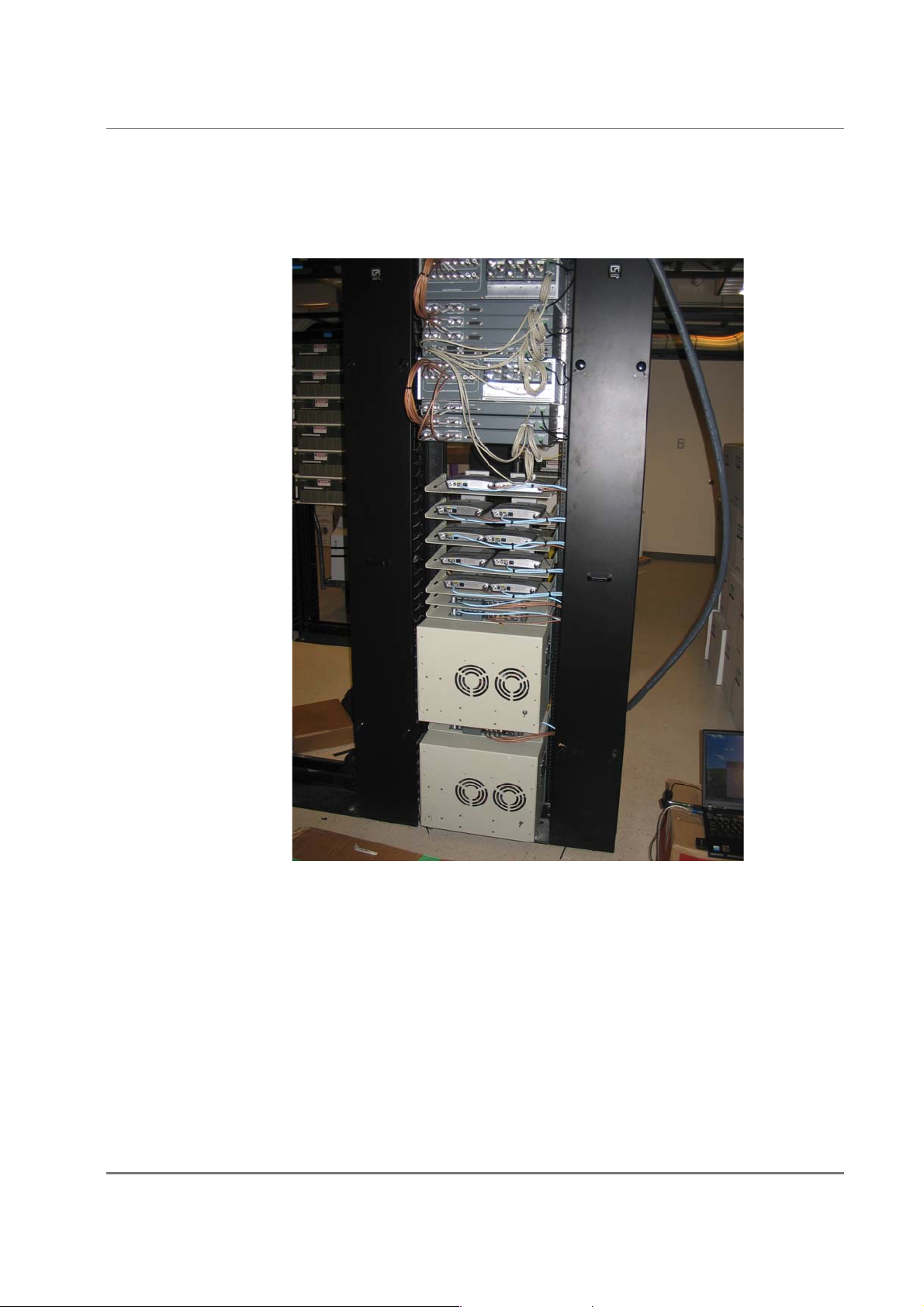
MobileAccess has also found that mounting the access points in a 19” rack system has proven to
be effective against RF leakage between access points. In this configuration as detailed in the
picture below, two access points can be installed per 19” shelving unit which takes up 1U of
space per two access points.
MA-860 Installation and Configuration Guide 21
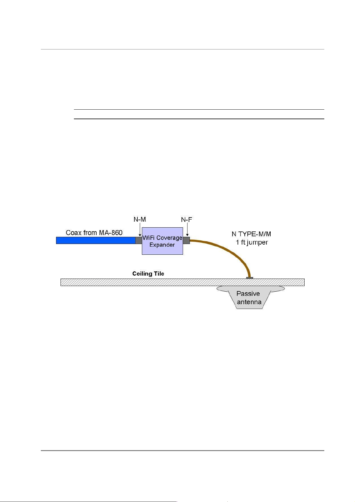
4.3 Wi-Fi Coverage Expander (WCE) Installation
Note: It is assumed the antennas have already been installed at the remote locations.
A WCE unit is installed near each antenna. The WCE can be installed in the following
configurations:
• Tie-Wrap / Wire-Tie to a fixture
• Wall Mounted – using four screws
• In-line with the coax cables
The WCE will be connected on one side to a 0.5'' low loss coaxial cable (typically running to a
remote wiring closet), and to the Passive Broadband Antenna usually through a jumper (flexible
1' coax cable). The following sections illustrate each type of WCE installation.
Installation
0.5'' low loss coaxial cable
Up to 250 ft
1' coax cable
MA-860 Installation and Configuration Guide 22
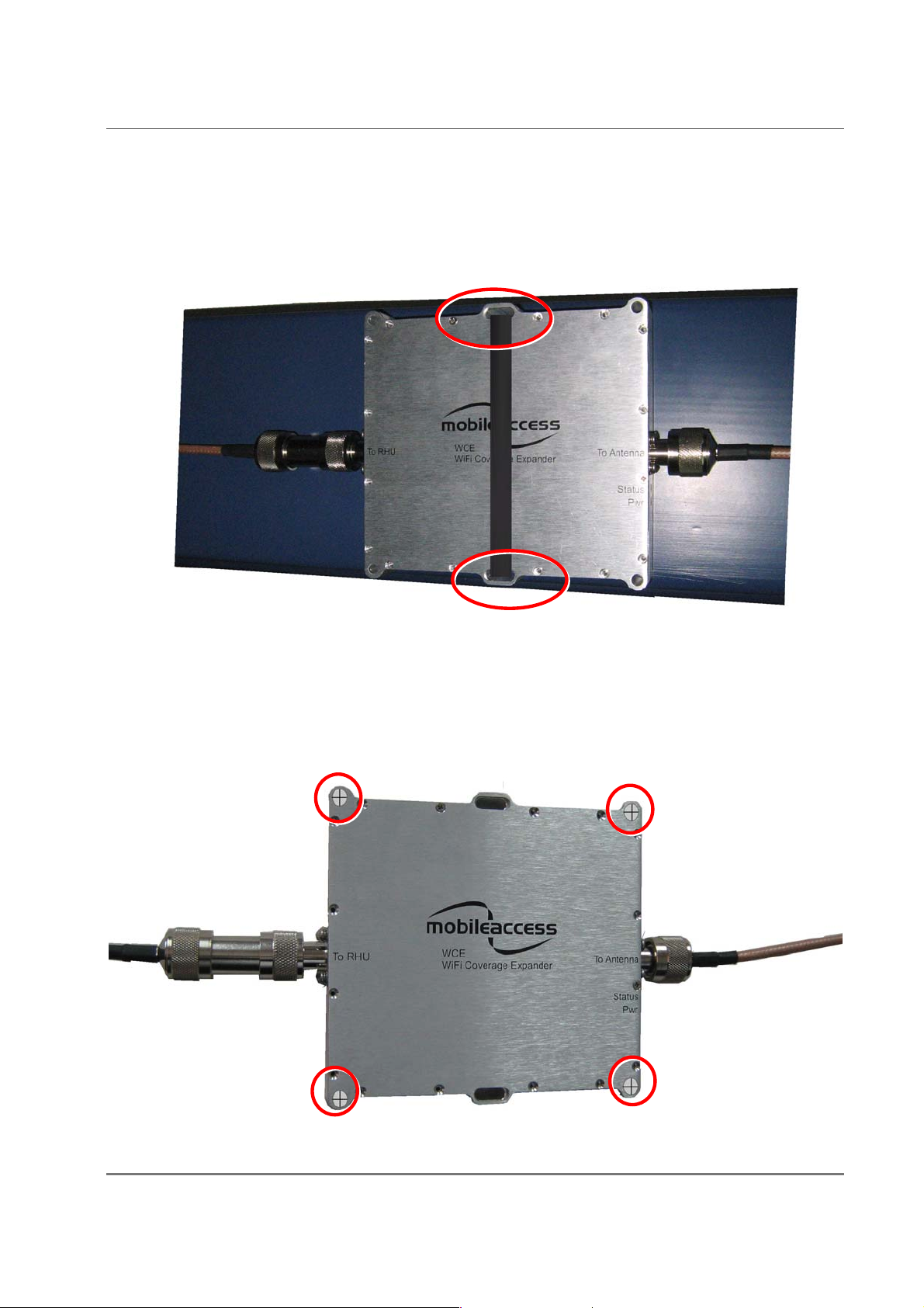
4.3.1 WCE Tie to Fixture Installation
Use the two mounting slots used to affix the unit to any available building infrastructure via a
wire-tie or tie-strap.
Installation
4.3.2 WCE Wall Mounted Using Four Screws
Secure the WCE using four standard drywall screws (3/16” in diameter).
MA-860 Installation and Configuration Guide 23

4.3.3 In Line with Coax Cables
WCE’s light design enables connecting it between the two coax cables without additional
support.
NOTE: The bending moment for ½” coax cable = 3lbs per foot.
4.4 860 WLAN Module Installation
MA 860 can be mounted in the following configurations:
• Standalone – mounted directly on the wall with four screws
• Mounted onto an MA 1000 RHU
• Mount as add-on to an MA 1000 RHU with an MA 1200 add-on unit
Installation
• Add-on to a MA 2000 system
To install the unit
• Depending on your installation mount the unit on the IDF or telecom Closet wall (standalone
installation) or assemble it onto the MA system (when converged with other MA systems)
• Record location and serial number of MA860 unit
MA-860 Installation and Configuration Guide 24
 Loading...