

Page 1

MobileAccess™ 850
Installation and Configuration Guide
UM 850, Rev 1.2
August, 2004
UM 850, Rev 1.2 I
Page 2

Introduction MobileAccess™ 850
MobileAccess Ltd. Vienna, Virginia Tel: +1-703-848-0200
MobileAccess Ltd. Lod, Israel Tel: +972-8-9183888
http://www.MobileAccess.com
Email: sales@MobileAccess.com
Copyright © 2004 MobileAccess.
© 2004 by MobileAccess
This document contains confidential and proprietary information of MobileAccess
and may not be copied, transmitted, stored in a retrieval system or reproduced in
any format or media, in whole or in part, without the prior written consent of
MobileAccess. Information contained in this document supersedes any previous
manuals, guides, specifications, data sheets or other information that may have
been provided or made available to the user. This document is provided for
informational purposes only, and MobileAccess does not warrant or guarantee the
accuracy, adequacy, quality, validity, completeness or suitability for any purpose of
the information contained in this document. MobileAccess reserves the right to make
updates, improvements and enhancements to this document and the products to
which it relates at any time without prior notice to the user. MOBILEACCESS
MAKES NO WARRANTIES, EXPRESS OR IMPLIED, INCLUDING, WITHOUT
LIMITATION, THOSE OF MERCHANTABILITY AND FITNESS FOR A
PARTICULAR PURPOSE, WITH RESPECT TO THIS DOCUMENT OR ANY
INFORMATION CONTAINED HEREIN.
TRADEMARK ACKNOWLEDGEMENT
MobileAccess
TM
is a registered trademarks of MobileAccess. This document contains
other trademarks, trade names and service marks of MobileAccess and other
organizations, all of which are the property of their respective owners.
II UM 850, Rev 1.2
Page 3

MobileAccess™ 850 Introduction
POLICY FOR WARRANTEE AND REPAIR
MobileAccess tests and inspects all its products to verify their quality and reliability.
MobileAccess uses every reasonable precaution to ensure that each unit meets their
declared specifications before shipment. Customers should advise their incoming inspection,
assembly, and test personnel about the precautions required in handling and testing our
products. Many of these precautions can be found in this manual.
The products are covered by the following warranties:
General Warranty
MobileAccess warrants to the original purchaser all standard products sold by MobileAccess
to be free of defects in material and workmanship for one (1) year from date of shipment from
MobileAccess. During the warranty period, MobileAccess will repair or replace any product
that MobileAccess proves to be defective. This warranty does not apply to any product that
has been subject to alteration, abuse, improper installation or application, accident, electrical
or environmental over-stress, negligence in use, storage, transportation or handling.
Specific Product Warranty Instructions
RETURNS
All MobileAccess products are warranted against defects in workmanship, materials and
construction, and to no further extent. Any claim for repair or replacement of units found to be
defective on incoming inspection by a customer must be made within 30 days of receipt of
shipment, or within 30 days of discovery of a defect within the warranty period.
This warranty is the only warranty made by MobileAccess and is in lieu of all other
warranties, expressed or implied. MobileAccess sales agents or representatives are not
authorized to make commitments on warranty returns.
In the event that it is necessary to return any product against above warranty, the
following procedure shall be followed:
1. Return authorization is to be received from MobileAccess prior to returning any
unit. Advise MobileAccess of the model, serial number, and discrepancy. The
unit may then be forwarded to MobileAccess, transportation prepaid. Devices
returned collect or without authorization may not be accepted.
2. Prior to repair, MobileAccess will advise the customer of our test results and any
charges for repairing customer-caused problems or out-of-warranty conditions
etc.
3. Repaired products are warranted for the balance of the original warranty period,
or at least 90 days from date of shipment.
UM 850, Rev 1.2 III
Page 4

Introduction MobileAccess™ 850
LIMITATIONS OF LIABILITIES
MobileAccess's liability on any claim, of any kind, including negligence for any loss or
damage arising from, connected with, or resulting from the purchase order, contract,
quotation, or from the performance or breach thereof, or from the design, manufacture, sale,
delivery, installation, inspection, operation or use of any equipment covered by or furnished
under this contact, shall in no case exceed the purchase price of the device which gives rise
to the claim.
EXCEPT AS EXPRESSLY PROVIDED HEREIN, MOBILEACCESS MAKES NO WARRANTY, EXPRESSED OR
IMPLIED, WITH RESPECT TO ANY GOODS, PARTS AND SERVICES PROVIDED IN CONNECTION WITH THIS
AGREEMENT INCLUDING, BUT NOT LIMITED TO, THE IMPLIED WARRANTIES OF MERCHANTABILITY AND
FITNESS FOR A PARTICULAR PURPOSE. MOBILEACCESS SHALL NOT BE LIABLE FOR ANY OTHER
DAMAGE INCLUDING, BUT NOT LIMITED TO, INDIRECT, SPECIAL OR CONSEQUENTIAL DAMAGES ARISING
OUT OF OR IN CONNECTION WITH FURNISHING OF GOODS, PARTS AND SERVICE HEREUNDER, OR THE
PERFORMANCE, USE OF, OR INABILITY TO USE THE GOODS, PARTS AND SERVICE.
REPORTING DEFECTS
The units were inspected before shipment and found to be free of mechanical and electrical
defects.
Examine the units for any damage that may have been caused in transit. If damage is
discovered, file a claim with the freight carrier immediately. Notify MobileAccess as soon as
possible.
NOTE: Keep all packing material until you have completed the inspection
WARNING: To comply with FCC RF exposure compliance requirements, antennas used for
this product must be fixed mounted on indoor permanent structures, providing a separation
distance of at least 20 cm from all persons during normal operation.
WARNING: Antenna gain should not exceed 10dB.
WARNING:
minimum separation distance of 20 cm or more from all persons and must not be co-located
with any other antenna for meeting RF exposure requirements.
WARNING:
Compliance with RF safety requirements:
MobileAccess™ products have no inherent significant RF radiation.
The RF level on the down link is very low at the remote hub unit downlink ports. Therefore,
there is no dangerous RF radiation when the antenna is not connected.
Each individual antenna used for this transmitter must be installed to provide a
The design of the antenna installation needs to be implemented in such a way so as to
ensure RF radiation safety levels and non- environmental pollution during operation.
IV UM 850, Rev 1.2
Page 5

MobileAccess™ 850 Introduction
CERTIFICATION
MobileAccess products have met the approvals of the following certifying organizations:
ISO 9001:2000 (from March 15, 2004)
For US: FCC 47 CFT part 15
UM 850, Rev 1.2 V
Page 6

Introduction MobileAccess™ 850
Preface
This user guide provides all the information necessary to install and configure the
MobileAccess 850 systems.
Revision History
The revision history for this document is shown in Table 1-1.
Table 1-1: Revision history
Version Date Description
1.0 February 2, 2004 Preliminary version.
1.1 May, 2004 Final editing for initial version.
1.2 2-Aug,2004 FCC remarks
VI UM 850, Rev 1.2
Page 7

Table of Contents
Chapter 1. Introduction............................................................................................................... 9
1.1 About MobileAccess 850™.................................................................................................... 9
Chapter 2. System Description ................................................................................................ 11
2.1 Unit Description.................................................................................................................... 11
2.2 Block Diagram...................................................................................................................... 13
Chapter 3. Infrastructure Preparation .....................................................................................14
3.1 Installation Requirements ....................................................................................................14
3.2 Coaxial Cable Connections.................................................................................................. 14
3.2.1 General Cable Installation Procedures .......................................................................14
3.2.2 Additional Information .................................................................................................15
3.3 In-building Antennas ............................................................................................................15
3.3.1 Antenna Connections .................................................................................................16
3.4 Access Points ......................................................................................................................16
3.5 Power Connections.............................................................................................................. 16
Chapter 4. Installation............................................................................................................... 17
4.1 Acessory Kits ....................................................................................................................... 17
4.2 Positioning the Unit ..............................................................................................................17
4.3 MA 850 Installation and Connections ..................................................................................18
4.3.1 Wall Mount Standalone............................................................................................... 18
4.3.2 Wall Mount as Add-on to MA 1000 .............................................................................19
4.3.3 Add-on to MA 1200 and MA 1000 ..............................................................................20
4.3.4 Assembling to the Side of a ModuLite Cabinet........................................................... 21
4.4 AP Configuration and Connections...................................................................................... 22
4.4.1 802.11a AP Connections ............................................................................................23
4.4.2 Connecting MobileAccess Remote Units.................................................................... 24
4.4.3 Connection to Antennas .............................................................................................24
4.4.3.1 Connection to Power......................................................................................24
Chapter 5. Remote Management.............................................................................................. 25
5.1 IP Configuration Procedure.................................................................................................. 25
5.1.1 Connecting to the Network .........................................................................................26
5.1.2 Installing and Launching Lantronixs DeviceInstaller................................................... 26
5.1.3 Performing Auto-Discovery......................................................................................... 26
5.1.4 Assigning a Static IP Address..................................................................................... 27
UM 850, Rev 1.2 VII
Page 8

Introduction MobileAccess™ 850
5.1.5 Configuring the SNMP Parameters ............................................................................ 30
5.1.6 Configuring Serial Parameters ................................................................................... 31
5.2 Login to the Configuration Application ................................................................................. 32
5.3 Main Window ....................................................................................................................... 33
5.3.1 Changing AP Configuration ........................................................................................ 34
5.3.2 Monitoring Alarms....................................................................................................... 35
5.3.3 Gain Setting................................................................................................................ 36
Chapter 6. SNMP Management Using Any Standard SNMP Manager.................................. 37
Chapter 7. Upgrading MA 850 .................................................................................................. 38
7.1.1 Upgrading the Management Application .................................................................... 38
VIII UM 850, Rev 1.2
Page 9

Chapter 1. Introduction
1.1 About MobileAccess 850™
MobileAccess 850
Access Points. It significantly expands 802.11 coverage and enables distributing
data and voice services over a single coax and antenna infrastructure that supports
other MobileAccess products.
MA 850 enables concentrating the 802.11a/b/g APs on each floor or coverage area
in one location in the telecommunication closet or shaft where the MA 850 is also
mounted. The APs, along with voice services from another MA remote unit can all be
connected to the MA 850 to which the antennas are also connected.
MA 850 can be easily configured (through intuitive GUI) to distribute the AP signals
to selected antennas in order to provide the best coverage for a specific area.
Several configurations are available. As a result, less APs are required. As capacity
needs grow, more APs can simply connected to the MA 850. The number of APs
and channels can be optimized according to capacity needs and not according to
coverage area.
MA 850 can be installed in the following configurations:
• Standalone – to provide coverage only for 802.11a/b/g services
• Add-on to ModuLite MRC – to converge data services with the voice services
supported by the housed MRUs.
Add-on to a MobileAccess 1000 series RHU
•
• Add-on to a MobileAccess 1200 RHU
provides secure and centralized connection for 802.11a/b/g
The following illustration shows the MA 850 unit. Its dimensions and exact
specifications are described in section Error! Reference source not found..
Figure 1-1. MobileAccess 850 view
ModuLite User’s and Installation Guide 9
Page 10

Introduction MobileAccess™ 850
MA 850 Features and Capabilities
Supports simultaneous extension and distribution of:
•
• 1 to 4 802.11b/g APs user selected via intuitive graphical interface
• 1 to 4 802.11a APs
• Mobile services from MobileAccess 1000, ModuLite or Litenna RHUs
• Simplifies installation and maintenance:
• All active elements are in the telecom shaft or closet
• All data and voice services distributed via a common coax cabling and
broadband antennas
• Expanded coverage and reduced interference, significantly reduces the
number of necessary Access Points and saves on channel allocation
Scalable: Additional APs connected as needed
•
• AP signal distribution remotely configured from any Web Browser through
intuitive GUI
• Remote monitoring through a standard MIB browser
10 UM 850, Rev 1.2
Page 11
MobileAccess™ 850 System Description
A
Chapter 2. System Description
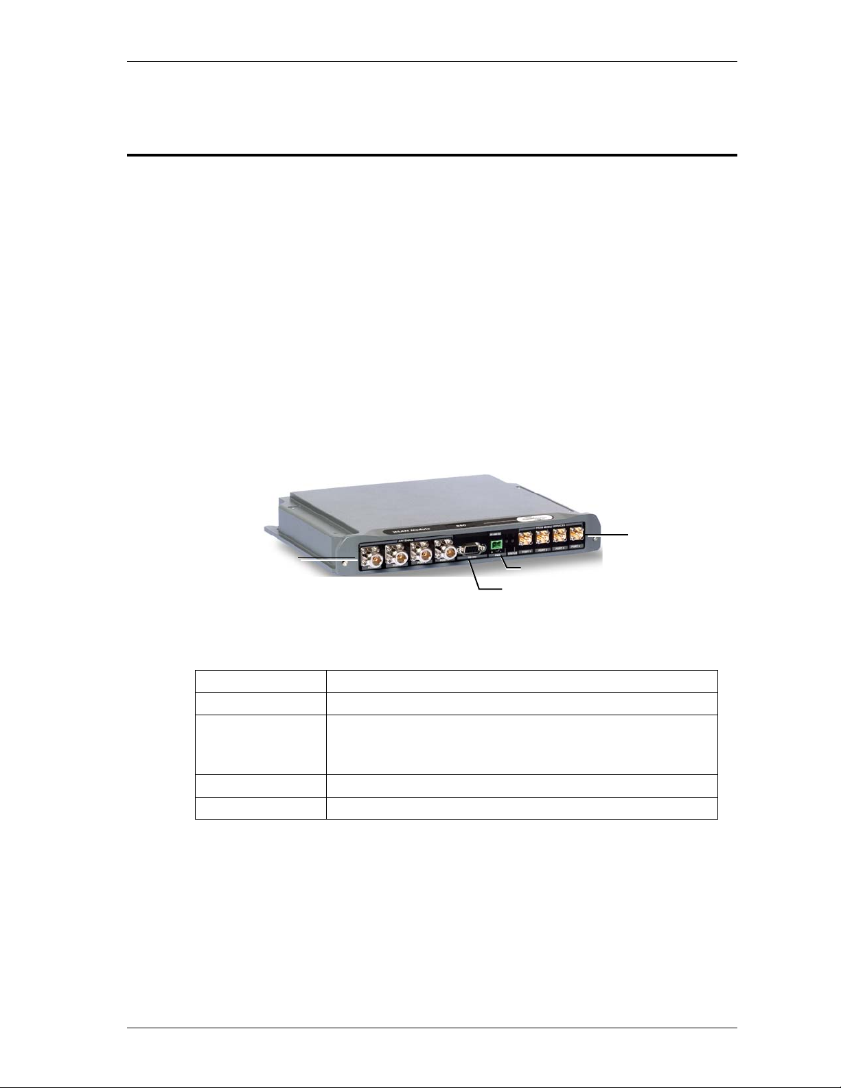
2.1 Unit Description
802.11a/b/g service ports and the Ethernet port for remote management are located
at the rear panel, while the antenna and MA RHU connections are at the front panel.
The unit is configured locally by connecting to the front panel Local connector.
Two monitoring options are provided (both located at the rear):
• Control connector to an MA RHU unit, enabling MA 850 to send SNMP
control signals through the RHU.
• Ethernet connection enabling direct remote monitoring
The following figure shows the MA 850 front panel, while Figure 2-2 shows the rear
panel.
Connections to
corresponding antenna
ntenna ports
Figure 2-1. MobileAccess 850 Front Panel View
Front Panel Description
Antenna Ports Four n-type female antenna connections
Mobile Services Four SMA female connections to antenna ports of MA RHUs (MA
1000, Litenna or Modulite).
To be terminated with 50 ohm terminations when not in use
Local Local connection for setup
DC Power connection: 20V to 48V from a standard power supply
Power
Local RS232 connection
for configuration
ports of MA RHUs
UM 850, Rev 1.2 11
Page 12
System Description MobileAccess™ 850
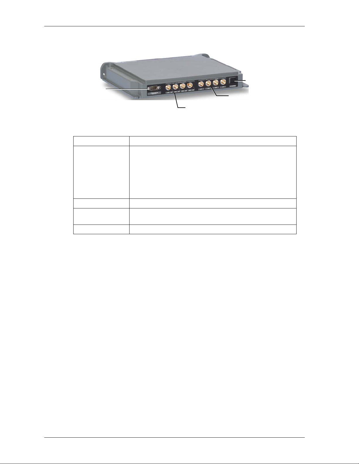
Ethernet
Connection to
add-on control
802.11 b/g APs
connections
Port
802.11 a APs
connections
Figure 2-2. MobileAccess 850 Rear Panel View
Rear Panel Description
802.11b,g APs Connection to up to four 802.11b/g APs, where associated LED
light under the following conditions:
• Green: indicates where AP should be connected after
configuration
• Green flickering: Link with AP established but no data is
received
• Red: AP transmitting data
802.11a APs
Connection to
control
Connection to up to four 802.11a APs
Connection to MobileAccess RHU RS232 connector for viewing
antenna status
Ethernet port Connection to network for configuration
12 UM 850, Rev 1.2
Page 13

MobileAccess™ 850 System Description
A
t
2.2 Block Diagram
MA 850 consists of the following main functional units:
• Programmable selection mechanism: Determines, according to user
definitions, the antenna outputs to which the 802.11b/g inputs will be routed.
(Only 802.11b/g APs routing can be user defined; 802.11a APs routing is not
currently configurable).
• Gain control mechanism: Amplifies the 802.11b/g signals.
• Combining and separating mechanism: On the downlink, combines the
amplified 802.11b/g signals with the 802.11a AP signals and the voice
services signals. On the uplink, separates the signals and routes them to the
corresponding outputs.
• Monitoring and control: Provides access to local RS232 configuration
options and to remote SNMP monitoring and configuration options.
802.11b/g APs
SNMP
Managemen
Local Setup
Monitoring and Control
Programmable
Selection
Gain Control
Voice services
4x 802.11a APs
Combining
(downlink) and
Separating (uplink)
ntenna output
ports
Figure 2: MobileAccess 850 Functional Block Diagram
NOTE: If the MobileAccess 850 is operated without cellular service, it is required to connect 50 Ω
termination points to each of the remote connectors in the unit. A 50 Ω termination is also required on
each unused AP port.
UM 850, Rev 1.2 13
Page 14

Infrastructure Preparation MobileAccess™ 850
Chapter 3. Infrastructure
Preparation
3.1 Installation Requirements
NOTE: To support services between 800 Mhz to 6 Ghz (Cellular, PCS, 802.11a/b/g), the installed
antennas must be of a broadband type that support all the mentioned services.
The infrastructure preparation consists of two main phases:
A. Floor Planning: Planning the distribution of the antennas on each floor to
provide the required coverage. This phase varies depending on whether the
coverage is only for WLAN or includes voice coverage and on the existing
infrastrucutre:
• For WLAN coverage only:
•
For voice and WLAN coverage – no exisitng infrastructure:
antennas are required.
• For voice and WLAN coverage – existing infrastructure: verify the
coverage takes into account the extended coverage provided by MA 850 and
the simplified infrastructure that supports both voice and WLAN services.
B.
Telecom Closet Planning:
telecom closet or shaft. This includes the MA 850, 802.11 Access Points, cabling
and other voice service distribution systems such as MA 1000 that are relevant
to the specific installation.
only WLAN antennas are required.
Planning the layout of the devices and cables in the
3.2 Coaxial Cable Connections
3.2.1 General Cable Installation Procedures
The general cable installation procedures in accordance with the building codes in
your area should be observed. The building code requires that all cabling be
installed above ceiling level (where applicable). Each length of cable from the risers
to each antenna must be concealed above ceiling.
The cable must be properly supported and maintained straight. This is either by tie
wraps or cable trays and clamps or hangers every 10 feet (where practical above
ceiling level). Where this is not obtainable, the following should be observed:
broadband
• The minimum bending radius of the supplied ½” coax cable should be 7”.
• Cable that is kinked or has a bending radius smaller than 7” must be
replaced.
14 UM 850, Rev 1.2
Page 15

MobileAccess™ 850 Infrastructure Preparation
• Cable runs that span less than two floors should be secured to suitably
located mechanical structures.
• The cables should be supported only from the building structure.
3.2.2 Additional Information
• Use coax ½”, 50ohm, male-to-male N-type, (6-7dB for 1Ghz, 11dB for 2Ghz)
for connecting to MRC ports.
• Use VSWR meter (Site Master) for checking coax cables, including the
antennas. (<2).
Unconnected
•
MA 850
ports should be terminated with a 50 ohm load.
3.3 In-building Antennas
The in-building antennas are connected to the coaxial cable distribution system by
jumper cables at various points. The antennas will be mounted on the ceiling tiles
and should be exposed. All in-building antenna installations will be such that it will
not interfere with indoor traffic and will not enable any person to touch the antennas.
Wideband antennas omni/directional – up to 2.5GHz to support 802.11b/g,
•
up to 6GHz to support 802.11a
• 50 ohm impedance
NOTE: The following vendor antennas have been verified. Although most other broadband
antennas can be used, it is recommended to contact your MobileAccess representative to verify
that your antennas are suitable for use with your installed MobileAccess system.
Antennas:
Vendor Catalog number Gain [dBi]
Mars
Antennas
Cellwave A08818DC00-28T0 2.1
Antenna
Specialists
MA-CM36-15 2 low band
ASP-3561 2
3-4 high band
5 WLAN 802.11b
UM 850, Rev 1.2 15
Page 16

Infrastructure Preparation MobileAccess™ 850
3.3.1 Antenna Connections
50 Ω, 1/2” or 3/8” Plenum coax cables
•
• Max cable length (typically): 150’
• 50 ohm terminator on unused connections
• For short jumpers (to MRC antenna ports): RG223 2 ft or 10 ft male-to-male
coax jumpers
3.4 Access Points
NOTE: The following vendor APs have been verified and approved in the FCC filing. In order to
meet the FCC requirement 15.204 it is required to put a new FCC ID label that will cover the
original label.
Access Points:
Vendor Catalog number
Cisco AIR-AP1200 series AIR-MP20B
3.5 Power Connections
The power connections vary according to the MA 850 installation topology.
The following power supplies are recommended for local power configuration:
NOTE: Power can also be supplied using remote power supply configurations.
• Standalone (WLAN only) – dedicated power supply (i.e. LPS-48-40W – refer
to the Power Supplies Manual).
• Mounted to the ModuLite™ MRC – same as standalone. Dedicated power
supply (i.e. LPS-48-40W – refer to the Power Supplies Manual).
As an add-on to the MA 1000 RHU – recommended PS: LPS-48-100W
•
(100W, 48V PS) which supplies both modules.
16 UM 850, Rev 1.2
Page 17

MobileAccess™ 850 Installation
A
Chapter 4. Installation
4.1 Acessory Kits
Verify that the supplied accessory kit corresponds to your installation. The accessory
kits include a bracket, the required cables and accessories.
AK-850-1000 Accessory kit for 850 with 1000
AK-850-1200 Accessory kit for 850 with 1200
AK-850-MDLT Accessory kit for 850 with Modulite
AK-850-2000 Accessory kit for 850 with 2000
AK-850-SA Accessory kit for 850 stand alone
4.2 Positioning the Unit
MobileAccess 850 is typically installed in the communication shaft or cabinet of
each floor to which WLAN coverage is to be supported. The accessories, mounting
and installation procedures vary depending on the configuration.
The following devices and cabling are connected to the MA 850:
802.11a/b/g APs: Ethernet (LAN) and power connections. Take into account
•
additional APs that may be required in the future.
• MA 850: power and coax connections
• MobileAccess remotes for voice services: MA 1000 or ModuLite MRC
The following figure shows a simplified illustration of the positioning of MA 850,
along with the APs, cables, and MA 1000 RHU. The example represents MA 850 as
add-on to MA 1000.
AP
802.11a
APs
AP
802.11b/g
APs
Intermodule control and
antenna connections
MA 1000
MA 850
ntenna connections
CAT5 Network connection
for monitoring
Local RS232
setup connection
Figure 4-1.Example of MA 850 connections layout
UM 850, Rev 1.2 17
Page 18

Installation MobileAccess™ 850
4.3 MA 850 Installation and Connections
MA 850 may be installed in the following configurations:
• Wall mount standalone – mounted on the wall with four screws
• Wall mount as add-on to MA 1000 RHU
• Wall mount as add-on to MA 1200 RHU
• As add-on to a ModuLite Remote Control (MRC)
NOTE: It is recommended to record the location of the units according to the MAC addresses on the
sticker at the rear of the units near the Ethernet port.
In a wall-mount standalone configuration, MA 850 is mounted to the wall using four
screws. When connected to another MA remote (MRC, MA 1000 or MA 1200), a
special bracket and set of accessories is used. A different bracket and set of
accessories is used for each type of installation.
Note: Use SMA wrench for the SMA connectors, do not over tighten the connectors.
4.3.1 Wall Mount Standalone
NOTE: Cable 705102101 supplied with the MA 850 module is for use when MA 850 is installed in an
add-on configuration. Although it is not required for a stand-alone installation, it is recommended to set
is aside. You will need it if you want to upgrade your system to provide additional coverage options.
1. Mount the MA 850 on the wall using four screws. When mounting, take into
account:
• That the type of screws used must suit the type of wall construction (cement,
bricks, etc.) so that the mount is secure.
• The position of the APs and required cable connections.
2. Connect the power and coax antenna cables to the MA 850 unit.
3.
Configure
4. Fit 50 ohm terminators on all unconnected SMA, AP and antenna ports.
the unit and connect the
according to section 4.4.
APs
18 UM 850, Rev 1.2
Page 19

MobileAccess™ 850 Installation
4.3.2 Wall Mount as Add-on to MA 1000
1. Mount the MA 850 unit on the wall using four screws inserted in the four side
holes.
2. Secure the supplied bracket to the top cover of the MA 850 through the six holes.
3. Assemble the MA 1000 RHU on top of the bracket.
4. Connect between
MA 850
and
MA 1000
as follows:
• Connect between the
Control
connectors at the rear of both units using
cable 705102101
705102101
.
• Connect the
Figure 4-2. Control connector
MA 1000 antenna
ports and the
MA 850 Mobile Services
using the four SMA to N-type cables supplied in the accessory kit. Be sure
the connectors are closed at a 45 degree angle so as not to place stress on
the cables.
ports
MA 850
Four antennas to
SPI connectors
Figure 4-3. Antenna to SMA Connections
5. Connect the
power
and coax
antenna
cables to the MA 850 unit.
6. Configure the MA 850 unit and connect the APs according to section 4.4.
7. Fit 50 ohm terminators on all unconnected SMA, AP and antenna ports.
UM 850, Rev 1.2 19
Page 20

Installation MobileAccess™ 850
4.3.3 Add-on to MA 1200 and MA 1000
The installation varies depending on whether the MA 850 is to be added to an
existing installation of MA 1200 and MA 1000 or if this is a new installation: if this is a
new installation, install the MA 850 first and mount the MA 1000 and MA 1200 on top
of the MA 850. Otherwise, install the MA 850 on top of the MA 1200.
As a new installation
1. Mount MA 850 on the wall using four screws inserted in the four side holes.
2. Secure the supplied bracket to the top cover of the MA 850 through the six holes.
3. Assemble the MA 1000 RHU on top of the bracket.
4. Assemble the
5. Connect the MA 1000 antenna ports and the MA 850 Mobile Services ports
using the four SMA to N-type cables provided in the accessory kit. Be sure the
connectors are closed at a 45 degree angle so as not to place stress on the
cables.
MA 1200 RHU
on top of the
MA 1000 RHU.
6. Connect between the MA 1200 RHU Add-on connector (at the rear) to the MA
850 Add-on connector (at the rear) using cable 705102101.
7. Connect the power and coax cables to the MA 850 unit.
8. Configure the unit and connect according to section 4.4.
9. Fit 50 ohm terminators on all unconnected SMA, AP and antenna ports.
20 UM 850, Rev 1.2
Page 21

MobileAccess™ 850 Installation
4.3.4 Assembling to the Side of a ModuLite Cabinet
Mount MA 850 on the side of a Modulite Remote Cabinet (MRC) using the supplied
“L” bracket and the two screws.
1. Loosen and remove the two screws on the MRC top panel, on the side on which
the MA 850 module will be mounted. Loosely insert the two screws provided by
MobileAccess (this is to verify that the used screws are long enough to
accommodated the additional height).
Replace these two
screws – do not tighten.
2. Fit the “L” bracket on the side of the cabinet – so it fits on the two screws and
tighten the screws.
3. Assemble the MA 850 onto the ‘L’ bracket and secure with the screws.
Figure 4-4. Assembly to the side of a ModuLite Cabinet
UM 850, Rev 1.2 21
Page 22

Installation MobileAccess™ 850
t
4.4 AP Configuration and Connections
802.11b/g connections must be configured in order to optimize AP coverage and
customize it to the specific area.
NOTE: 802.11a AP connections do not require software configuration: each connection is routed
directly to a specific antenna. The configuration can be modified anytime, either locally according to the
following procedure, or remotely according to the procedure described in Chapter 5 Remote
Management 802.11b/g Connections and Configuration
Before
connecting the devices and cables to the MA 850, configure the unit with the
connected APs. For one, three and four AP connections, the services are routed to
specific antennas – no choice is available to the user. For two AP connections, the
user may select from several configurations the antennas to which the services will
be routed.
After the configuration is completed, the appropriate LED indicating the valid
connection points for the APs will be lit.
To configure the MA 850
1. Install the 850 MA Setup application on your computer.
2. Locally connect to the MA 850
provided with the MA 850
3. Launch the application on the computer. The following dialog appears.
Select the relevant
configuration
connector using the RS232 9-pin cable
Local
Choose the com por
Click
Connect
configuration on MA 850
to enable the
Figure 4-5. MA 850 Setup Dialog
4. Select the com port and click Connect.
22 UM 850, Rev 1.2
Page 23

MobileAccess™ 850 Installation
5. In Select Configuration, choose the configuration corresponding to the number
of APs that will be connected. The MA 850 ports to which APs can be
connected will be indicated by lit LEDs.
Note that APs must be connected to specific ports according to the number of
APs. For example, a single AP is always connected to Port-1, and three APs are
connected to the corresponding ports 1 through 3.
In configurations with two APs, select the antennas to which services will be
routed so that the coverage is optimized.
# of 802.11b/g APs 802.11b/g Connections Output to Antenna Ports
1 AP Port #1 1,2,3,4
2 APs Ports #2, #3
3 APs Ports #1, #2, #3 AP1 to Antenna 1
4 APs Ports #1, #2, #3, #4 AP1 to Antenna 1
User configurable:
1. Port-2: Antennas 2,3; Port-3: Antennas 3,4
2. Port-2: Antennas 2,3,4; Port-3: Antenna 1
3. Port-2: Antennas 1,3,4; Port-3: Antenna 2
4. Port-2: Antennas 1,2,4; Port-3: Antenna 2
5. Port-2: Antennas 1,2,3; Port-3: Antenna 4
AP2 to Antenna 2
AP3 to Antennas 3,4
AP2 to Antenna 2
AP3 to Antenna 3
AP4 to Antenna 4
4.4.1 802.11a AP Connections
Antenna ports provide coverage to the parallel 802.11a AP ports. Therefore, when
connecting the 802.11 APs, keep in mind the area to be covered.
For example, connecting 802.11a APs to 802.11a inputs 2 and 3, will distribute
these signals though antenna ports 2 and 3. Connecting the 802.11a APs to 802.11a
inputs 1, 2 and 3, will distribute the signals over antenna ports 1, 2 and 3.
NOTE: All coverage is combined. The antennas to which 802.11a signals are routed may, at the same
time, provide coverage for 802.11b/g and to voice services.
UM 850, Rev 1.2 23
Page 24

Installation MobileAccess™ 850
The following example shows that AP connections to 802.11a ports 2 and 3,
provides 802.11a coverage to areas covered by antennas 2 and 3 (the 802.11a
service connected to these ports is not covered by antennas 1 and 4).
802.11a AP
Antenna
3
Antenna
4
802.11a AP
MA 850
MA 1000 (voice)
Antenna
1
3
2
Antenna
2
4.4.2 Connecting MobileAccess Remote Units
• Use short 50 Ω Coax cables w/N-Type connectors
4.4.3 Connection to Antennas
• 50 Ω, N-type male to male, 1/2” or 3/8” Plenum coax cables
• Max cable length (typically): 150’
• 50 ohm terminator on unused connections
• For short jumpers (to MRC antenna ports): RG223 2 ft or 10 ft male-to-male
coax jumpers
Figure 4-6. Antenna Connections
4.4.3.1 Connection to Power
Connect the DC power supply…..20 VDC to 48 VDC
24 UM 850, Rev 1.2
Page 25

MobileAccess™ 850 Remote Management
Chapter 5. Remote Management
MA 850 whose SNMP parameters are defined may be connected to the network
through an Ethernet connection and assigned addresses either through dynamic
(DHCP) or static address assignment methods. The MA 850 units may then be
remotely managed from any Web Browser by connecting to the IP Address of the
specific MA 850 unit or through any Network Operating Center (NOC) using SNMP.
The following operations may be performed remotely through a Web browser:
• View the current Access Point configuration and make changes
View alarms
•
• View and change the current gain setting
Figure 5-1. MA 850 Remote Management
5.1 IP Configuration Procedure
MA 850 units connected to the network may be assigned either dynamic IP
Addresses through DHCP or static IP addresses (for networks without DHCP). The
addresses may be assigned from a single location using the Lantronixs
DeviceInstall
The IP configuration procedure consists of the following steps:
Installing and launching the
•
computer.
• Connecting to the network
• Performing auto-discovery
• For networks without DHCP – assigning IP Addresses manually
Setting the SNMP parameters
•
application supplied with the units.
Lantronixs DeviceInstaller
application on your
UM 850, Rev 1.2 25
Page 26

Remote Management MobileAccess™ 850
5.1.1 Connecting to the Network
Connect each MA 850 units first to the to the network and then to the power cable.
NOTE: It is recommended to record the location of the units according to the MAC addresses on the
sticker at the rear of the units near the Ethernet port.
5.1.2 Installing and Launching Lantronixs DeviceInstaller
5.1.3 Performing Auto-Discovery
1. Install and launch the Lantronixs DeviceInstaller application on your computer.
Figure 5-2. DeviceInstaller dialog
2. In the DeviceInstaller main window toolbar, click Search to perform auto-
discovery. The MA 850 units currently in the network will be identified and listed
in the window according to their MAC addresses (in the Hardware Address
column).
3. For networks with DHCP:
• The dynamically assigned IP Address will also be listed in the IP Address
column.
4. For networks without DHCP:
• Disregard the data displayed in the IP Address column and manually assign
a Static IP address.
What next ?
Define the SNMP parameters.
26 UM 850, Rev 1.2
Page 27

MobileAccess™ 850 Remote Management
5.1.4 Assigning a Static IP Address
NOTE: This procedure requires the MAC address of the MA 850, which is found on the label located at
the rear of the unit.
Perform the following procedure for each of the MA 850 units listed in
the Lantronix DeviceInstaller main window which are to be manually
assigned IP Addresses.
1. Select the MA 850 unit and click the icon Assign IP in the toolbar.
Figure 5-3. Assigning Static IP Address
2. The Device Identification window appears, showing the MAC address of the
selected MA 850 unit.
Figure 5-4. MAC Address
UM 850, Rev 1.2 27
Page 28

Remote Management MobileAccess™ 850
3. Click Next. The IP Address Assignment Method window appears.
Figure 5-5. Static IP Address
4. Select Assign a specific IP address; then, click Next. The IP Settings window
appears.
Figure 5-6. Static IP Address Definition
28 UM 850, Rev 1.2
Page 29

MobileAccess™ 850 Remote Management
5. Enter the IP Address, Subnet Mask and Default Gateway values; then, click
Next. The Assignment window appears.
Figure 5-7. Assignment Window
6. Click Assign to assign the MA 850 unit the defined parameters.
Once the parameters have been assigned, the message ‘Completed
Successfully’ appears and the Finish button is enabled.
Figure 5-8. Finish Static IP Address Definition
7. Click Finish. The Device Installer Main window reappears and the installed unit
will be listed in the window.
What next?
Define the SNMP parameters
.
UM 850, Rev 1.2 29
Page 30

Remote Management MobileAccess™ 850
5.1.5 Configuring the SNMP Parameters
Configure the SNMP Community and Trap destination addresses according to the
instructions in this section.
NOTE: The required communication parameters are pre-set for each MA 850 unit. However if you do
not succeed in connecting to the Telnet application, verify the communication parameters.
1. Select the MA 850 unit which will be configured (may be identified according to
its MAC address value) and click the Telnet button in the toolbar.
2. The Telnet dialog shows the IP address of the currently connected MA 850 unit.
Figure 5-9. Telnet IP Address window
3. Click OK and immediately press Enter to go into Setup Mode. The current
settings will be displayed, followed by the
Change Setup
menu.
Change Setup:
0 Server configuration
1 Channel 1 configuration
3 SNMP configuration
7 factory defaults
8 exit without save
9 save and exit Your choice ?
4. Enter 3 (SNMP Configuration).
5. Set the SNMP Read and Write community names and the SNMP traps
destination addresses (up to three addresses can be defined) by responding with
to the prompt
Y
Set the Gateway IP Address
and defining the Address (as
illustrated below).
SNMP community name for read (): public
SNMP community name for write (): private
Enter IP addresses for SNMP traps:
1: (000) 192.(000) 168.(000) 10.(000) 22
2: (000) .(000) .(000) .(000)
3: (000) .(000) .(000) .(000)
6. Press Enter to run through the rest of the parameters. When the Setup Menu is
displayed again, select 9 – Save and Exit.
30 UM 850, Rev 1.2
Page 31

MobileAccess™ 850 Remote Management
5.1.6 Configuring Serial Parameters
This section describes how to verify and configure the serial communication
parameters for each MA 850 unit.
1. From the DeviceInstaller Main window, select the MA 850 unit to be configured
and click the Configure button the toolbar. The Configure Device dialog
appears.
2. Click the
dialog appears.
Figure 5-10. Current Serial Port Parameters
tab and then the
Ports
Figure 5-11. Port Properties
Edit Settings…
button. The Port Properties
UM 850, Rev 1.2 31
Page 32

Remote Management MobileAccess™ 850
3. Set the parameters as follows: Baud Rate 19200, Data Bits 8, Parity None, Stop
Bits 1, Flow Control None; then, click OK. The DeviceInstaller Main window
appears.
5.2 Login to the Configuration Application
To login to the MA 850 configuration application
1. Run a Web Browser application (i.e. Internet Explorer).
2. Enter the IP Address of the MA 850 unit to be configured. (i.e.
http://192.168.10.127). The Login dialog appears.
3. Select the User as Admin or Guest; where Admin has configuration privileges
and Guest (default password = guestpass) may only view the current
configuration. Enter the Password and click Login. The Main configuration
window appears. The window shows the current configuration (Active
Configuration) and provides configuration and monitoring options. The Main
window is described in the following section.
32 UM 850, Rev 1.2
Page 33

MobileAccess™ 850 Remote Management
5.3 Main Window
The Main window is displayed upon login. The available options vary depending on
whether login was performed through Admin or through Guest authentication level.
The following options are available:
• Login – click to login using a different authentication level
• Active config – displays the current AP configuration
• Set AP config – modify the current AP configuration
• Alarms –
• Gain setting –
•
Logout –
displays any alarms from the connected MA 850
modifies gain setting (default = 0)
exit application and close connection
UM 850, Rev 1.2 33
Page 34

Remote Management MobileAccess™ 850
5.3.1 Changing AP Configuration
1. Click the Set AP Config in the Main window to display the Set AP Config
window.
2. Select the desired configuration. The corresponding image, displaying the
selected configuration appears.
3. Click Accept to upload the new configuration to the MA 850 unit.
34 UM 850, Rev 1.2
Page 35

MobileAccess™ 850 Remote Management
5.3.2 Monitoring Alarms
MA 850 provides the following alarms, which may be viewed by clicking the Alarms
button in the Main window:
•
Access Point Sense –
senses the connection of configured APs
• Low power – sense the power level at each AP input
• Antenna sense – senses connected antennas. This option can be disabled
for antennas that are not connected
UM 850, Rev 1.2 35
Page 36

Remote Management MobileAccess™ 850
5.3.3 Gain Setting
MA 850 enables the authorized user (Admin level) to adjust the gain for every
channel to counteract changes in the environment.
The Gain Setting dialog is accessed by clicking the Gain Setting button in the Main
window.
36 UM 850, Rev 1.2
Page 37

MobileAccess™ 850 SNMP Management Using Any Standard SNMP
Manager
Chapter 6. SNMP Management
Using Any Standard
SNMP Manager
The MA 850 packages provide MIBSs that enable standard SNMP managers such
as HP OpenView to view event traps sent by the MA 850 unit and to configure the
unit.
One MIB file is provided: MA-XPORT850-MIB– describes the architecture of the
managed elements and contains the events in the system
NOTE: These traps provide a general indication of the type of failure. The MA 850 enables identifying
the source of the problem and system monitoring parameters.
To view the traps using any standard SNMP manager
NOTE: It is assumed that the IP Address of at least one destination is already defined.
Load the two MIB files to the SNMP manager. The following figure shows the MIB
tree that includes the loaded MobileAccess 850 file.
Figure 6-1. MIB Tree with Loaded MobileAccess 850 Files
UM 850, Rev 1.2 37
Page 38

Chapter 7. Upgrading MA 850
Use the procedure described in this chapter to upgrade the MA 850 software.
7.1.1 Upgrading the Management Application
1. From the DeviceInstaller Main window, select the MA 850 unit to be upgraded
and click on the
appears.
Upgrade
icon in the toolbar. The Installation type dialog
2. Select
ModuLite User’s and Installation Guide 38
Use a specific installation file
, browse for the file and click
Next.
Page 39

MobileAccess™ 850 SNMP Management Using Any Standard SNMP
Manager
The update procedure begins.
3. Once completed, the following window appears.
4. Click Close to complete the procedure.
UM 850, Rev 1.2 39
 Loading...