

Page 1
Rack and Cabinet Installations
3.4 MA 850 Installations
MA 850 may be integrated into the MA 2000 system using one of the following installations:
Installing it directly on the MA 2000 RC top panel (using the supplied plate); •
• • Mounting it on a rack (using the supplied plate);
Wall mount near the MA 2000 cabinet.
The coax outputs of the cabinet are connected to the appropriate ports on the MA 850 and
the antennas are connected directly to the MA 850 module.
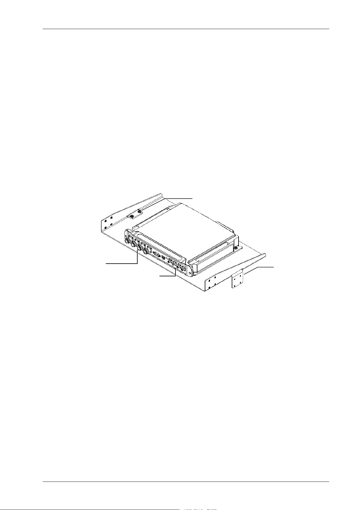
3.4.1 MA 850 RC 2000 Assembly
1. Assemble two side brackets to the plate sides as illustrated in Figure 3-10.
2. Assemble the MA 850 module to the supplied bracket using the four screws and washers
as illustrated below.
Side bracket
assembly
Connections to
antennas
Connections to Remote
Cabinet antenna ports
Figure 3-10. MA 850 Rack Installation
Side bracket
assembly
Installation and Configuration Guide 21
Page 2
Rack and Cabinet Installations
t
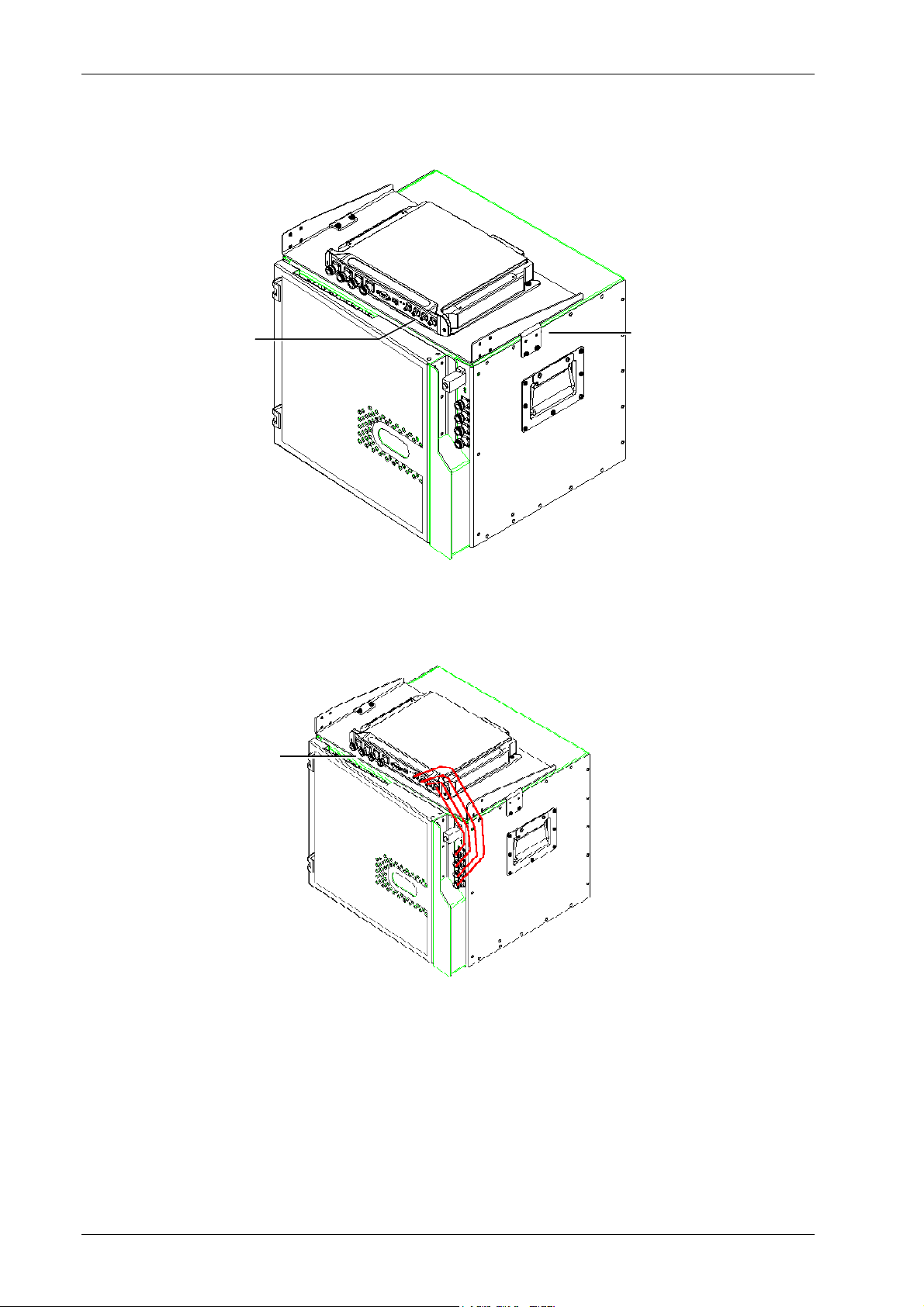
3. Assemble the plate to the MA 2000 RC by securing the brackets to the cabinet sides as
illustrated below.
Connection to
Remote Cabine
antenna ports
Plate assembly secured to
RC with side brackets
Figure 3-11. Illustration of MA 850 Mounted on MA 2000 RC
4. Connect the RC antenna ports to the MA 850 front panel port connectors as illustrated
below.
Connections to
antennas
Figure 3-12. Illustration of RC Antenna port connections
5. Connect the antennas to the MA 850 antenna ports.
22 Installation and Configuration Guide
Page 3
Rack and Cabinet Installations
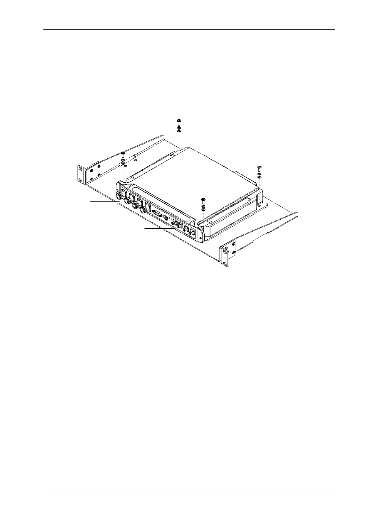
3.4.2 MA 850 Rack Mount
1. Assemble the side brackets as illustrated in Figure 3-10.
2. Assemble the MA 850 module to the supplied bracket using the four screws and washers.
3. Mount the assembly in the rack using the side brackets.
Connections to
antennas
Connections to
RC antenna ports
Figure 3-13. MA 850 to Bracket Installation
4. Connect the RC antenna ports to the SMA connectors on the MA 850 front panel.
5. Connect the antenna to the MA 850 antenna ports.
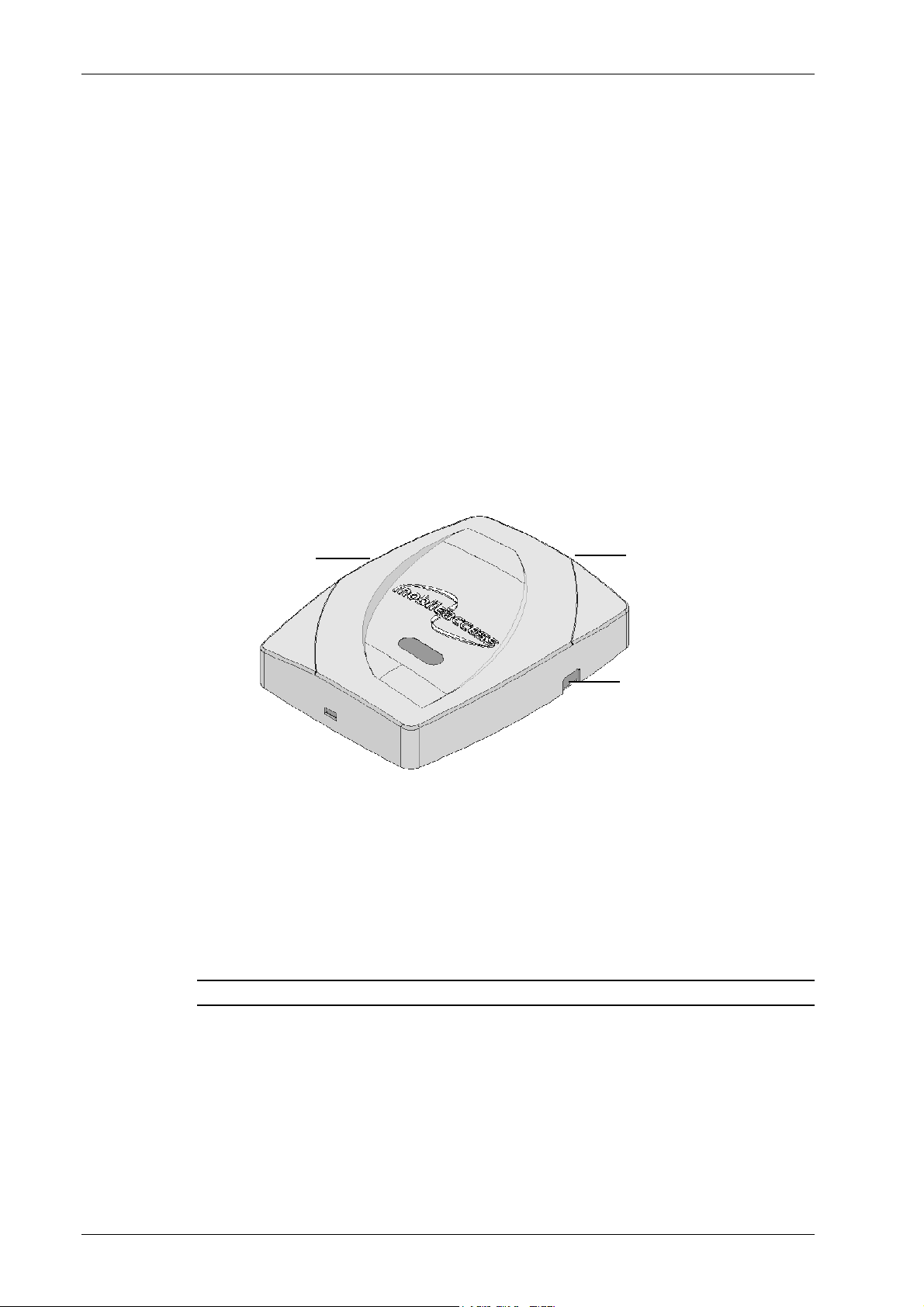
3.4.3 MA 850 Wall Mount Installation
The MA 850 may be mounted independently on the wall near the RC cabinet.
1. Connect the RC antenna ports to the SMA connectors on the MA 850 front panel.
2. Connect the antenna to the MA 850 antenna ports.
Installation and Configuration Guide 23
Page 4
Rack and Cabinet Installations
3.5 2000 Lite Installation and Connections
MA 2000 Lite is designed to be a wall mounted device. It is usually installed in the
communication shaft of the corresponding floor and is powered from an external power
source. It may also be connected to a backup battery.
The remote units are mounted externally to the 2000 Lite device and their antenna outputs
are connected to either side of the 2000 Lite device. The combined outputs are then
connected to the antennas in the covered area.
2000 Lite is capable of supporting two types of remote units: RU 2000 and MA 850
(wireless 802.11a/b/g coverage). A MA 1200 add-on module can be connected to each RU
2000 module to provide additional services.
The MA 2000 Lite connections are shown in the following figures. Note that the power
connections are on the underside, and the coax connections are at the sides of the modules.
Connections to RU antenna ports or
MA 850 SMA ports (if a MA 850
to
module is installed)
Figure 3-14. 2000 Lite System coax connections
3.5.1 MA 2000 Lite Coax Connections
1. Connect the RU 2000 antenna ports to the appropriate connectors at the side of the MA
2000 Lite module.
Connections to
Antennas
Connections to RU antenna ports
or to MA 850 SMA ports (if a MA
850 module is installed)
NOTE: The additional require RU 2000 connections are described in section 4.4 1. .
2. Connect the antennas to the MA 2000 Lite antenna ports.
3.5.2 MA 850 Installation Connections
1. Connect the 2000 Lite antenna ports to the MA 850 From Mobile Services
connectors on the MA 850 front panel.
2. Connect the antennas to the MA 850 Antenna ports.
24 Installation and Configuration Guide
Page 5

System Elements
4
4
4.1 Overview
This chapter describes each of the system elements, and their individual connections. It can
be used as reference to verify the connections of each module or to upgrade your system. In
order to describe the installation process clearly, it will be described as consisting of two
logical parts:
A. Telecommunications room – installing the RIUs, BUs, MA 410/430
controllers, and the required
room close to the RF signal source. This installation may differ between single
and multi-building topologies.
B. Remote locations – RC installations and connections. These are
mounts.
The installations for two basic topologies are described in detail: for single building and for
multi-building. By understanding the two generic installations you will be able to address any
variations in system deployment.
S
S
y
y
stt
s
e
m
e
m
passive equipment
Ell
E
in the telecommunication
e
e
m
m
e
e
usually
ntt
n
wall
s
s
NOTE: For installations that include the MA NMS: Once the installation has been
completed it can be verified using the MCT application (NMS User’s Guide) and the devices
monitored using the NMS Manager (NMS User’s Guide).
,
Installation and Configuration Guide 25
Page 6
System Elements
A
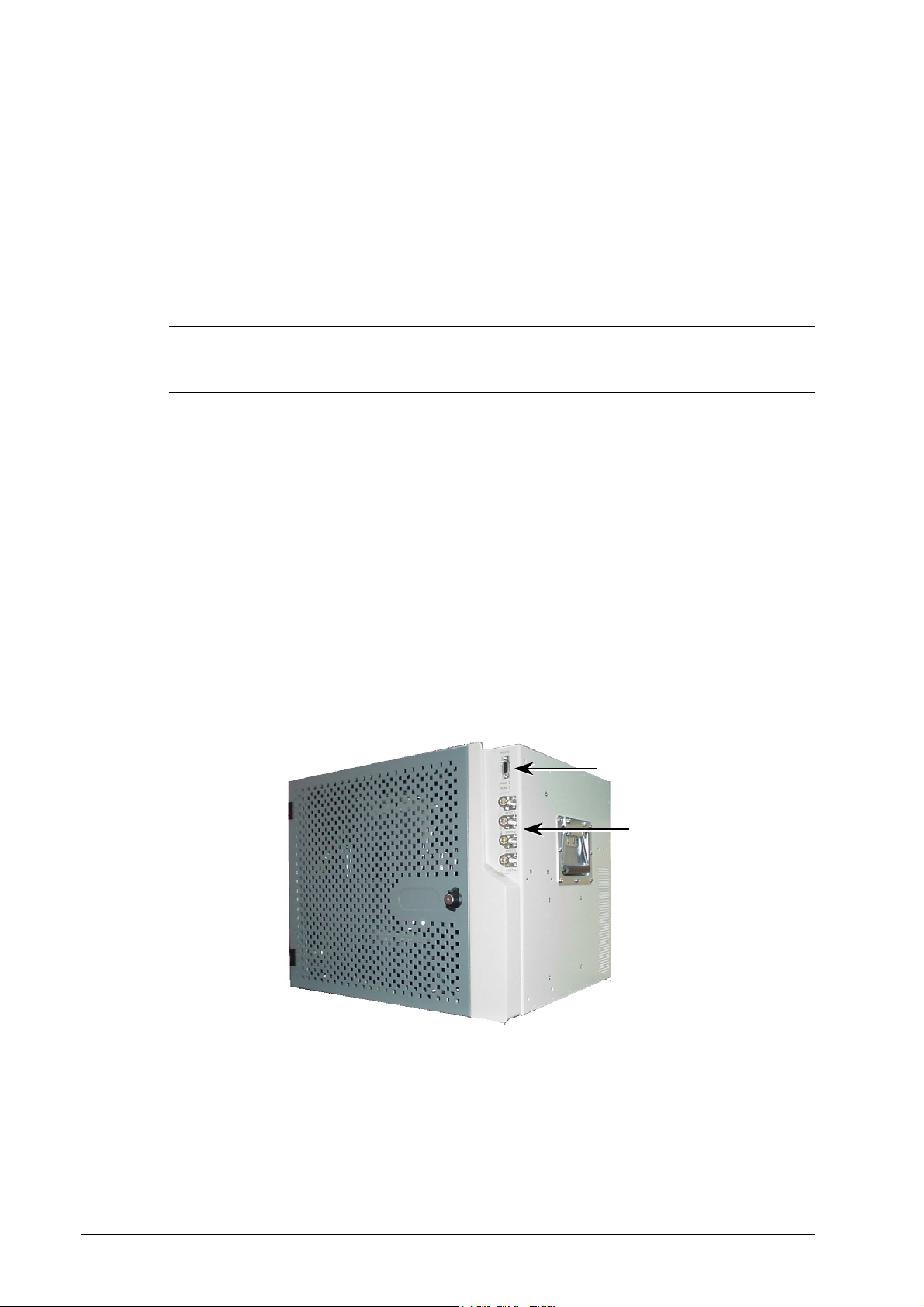
4.2 MA 2000 Remote Cabinet
The MA 2000 Remote Cabinet can house various combinations of up to five RU 2000 and MA
1200 add-on modules. The number of modules depends on the models, required filtering,
etc. In addition, a MA 850 module may be installed externally. The Remote Cabinet provides
the filtering, combining, power interface and antenna interface functions.
NOTE: If an MA 860 module is installed as well, the antenna outputs are further connected
to the appropriate connec ions on the MA 850 and the antennas then connec ed to the MA
850 antenna connections.
The optic connection from the BUs are routed internally and connected directly to the
corresponding RU 2000 module.
The MA 2000 Remote Cabinet is provided in two power configurations:
• Integrated power supply – a power supply is integrated into the cabinet and fed
from an external AC power source. The individual modules are internally connected
to the power supply. This model includes a battery connection as well.
t t
• External power supplies – the power source is external to the cabinet: it can be from
a central remote source (most common configuration) or from local installed
dedicated power supplies. Power is routed to external connectors on the Remote
Cabinet, where each external power connector is internally connected to a specific
module.
The cabinet may be mounted on a wall or in a 19” rack. The appropriate brackets are
provided with each type of installation.
The MA 2000 remote cabinet is illustrated below:
ntenna sensing monitoring
connection (future option)
4x coax cable
antenna ports
Figure 4-1. RC 2000 Closed Cabinet View
26 Installation and Configuration Guide
Page 7
System Elements
g
A
A
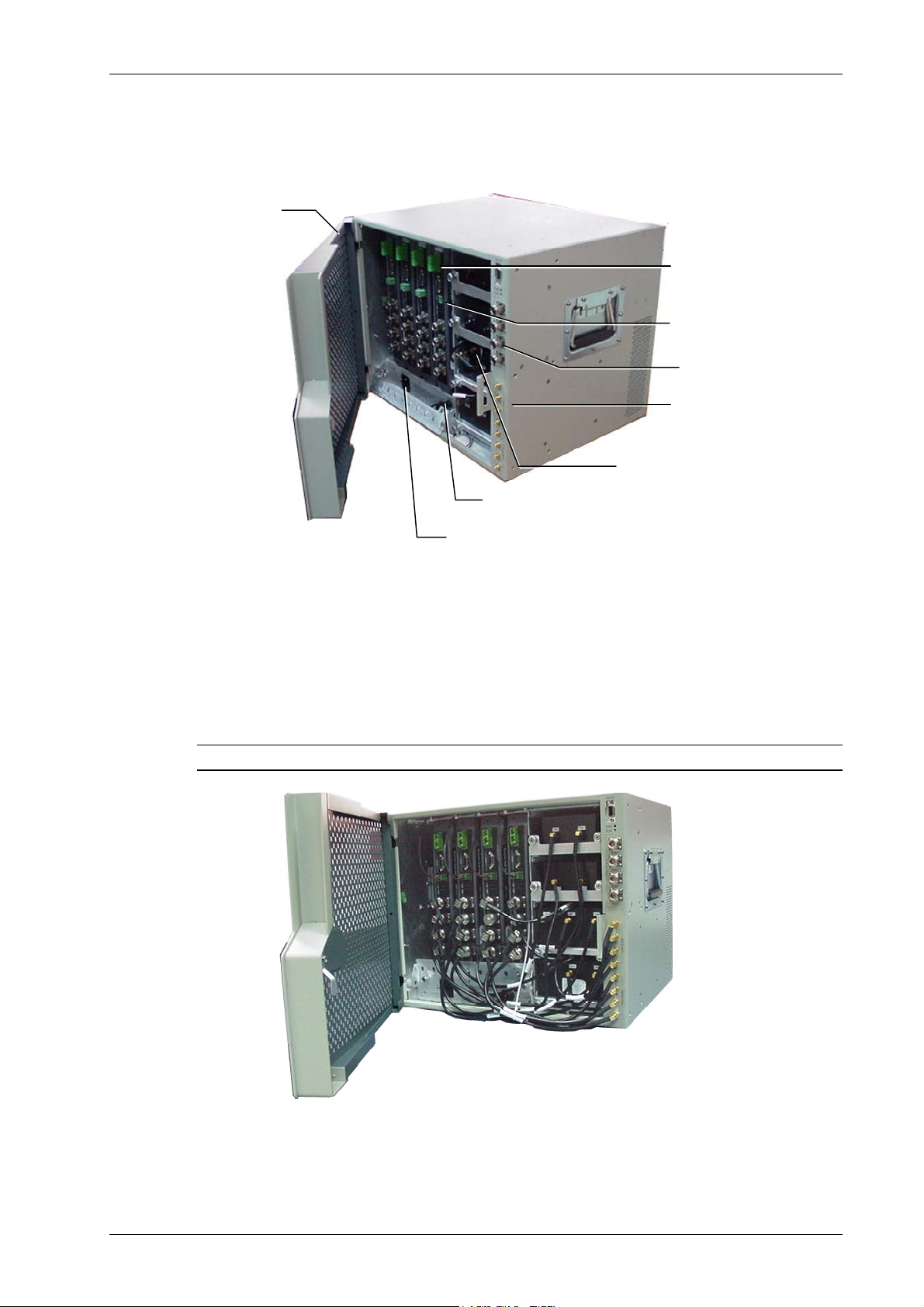
The following figure shows an open RC 2000 cabinet, integrated power supply model, with
four RU 2000 modules and four filters. (For clarity, the internal connections are not
included).
Slot for fittin
Optic Fibers
Optic fiber connection
from the corresponding
BU
Internal DC module
connections
ntenna ports
Splitter/Combiner
connections
Filters (four in this
configuration example)
Connection to
external battery
C power input to
integrated power supply
Figure 4-2. RC 2000 Open Cabinet View (without internal connections)
The following image shows the MA 2000 RC with the cabling. Note that the antenna ports of
the individual modules are connected to the internal RF connections (under the antenna
ports) and the filters as required. The PS connections of each module are also connected to
cables that are internally routed to the integrated PS.
NOTE: The fiber optic connections are not displayed.
Figure 4-3. RC Open Cabinet with Internal Cabling
Installation and Configuration Guide 27
Page 8
System Elements
4.3 MA 2000 2000 Lite Installation
The 2000 Lite provides the required interface and filtering required to support two RU 2000
modules to which MA 1200 add-on modules can be connected for additional services. This
MA 2000 configuration is fed from external power supplies. The RU 2000 modules, the
dedicated power supplies and any MA 1200 add-on modules are installed externally to the
2000 Lite.
Connections to RU antenna ports or
MA 850 SMA ports (if a MA 850
to
module is installed)
Figure 4-4. 2000 Lite System coax connections
4.3.1 Connections
1. Connect the power connections to the 2000 Lite, the MA 2000 RUs and any other
connected MA 1200 add-on modules.
Connections to
Antennas
Connections to RU antenna ports
or to MA 850 SMA ports (if a MA
850 module is installed)
2. Connect the antenna ports of each RU 2000 module to the appropriate connector on the
2000 Lite.
3. Connect the remote module optic fiber connections.
4. Connect the antenna coax infrastructure cables to the 2000 Lite connectors.
4.4 Remote Modules
The Optical to RF conversion of each service at the individual building floors is performed by
Remote Units (RU) 2000 modules corresponding to the service types. These consist of MA
2000 RUs and in addition, may include MA 1200 and MA 850 modules.
The location installations may be performed in various configurations depending on the
requirements of the site and the supported services. If a Remote Cabinet installation is
performed, the RU 2000 and MA 1200 modules are housed inside the cabinet while the MA
850 module is installed externally and integrated into the system. If a 2000 Lite installation is
performed, the modules are installed externally to the enclosure.
28 Installation and Configuration Guide
Page 9
System Elements
t
The following sections describe each of the elements and the connections as they relate to
the MA 2000 system.
4.4.1 Remote Units 2000
Each RU supports two different services (one high-band and one low-band). All RUs are
add-on ready, meaning that an additional (high-power) service can be added by connecting
a 1200 add-on module to the RU.
A fiber optic connection is implemented between each RU 2000 and corresponding BU. The
RU may be remotely monitored through the corresponding BU connection to the MA NMS.
The RU 2000 services, MA 1200 add-on service and MA 850 data services at each location
are combined prior to transmission to strategically placed antennas.
RU 2000 Front Panel
The RU 2000 front panel contains the fiber optic connections to the BU, four coax
connections to the antennas, power connections and status indicators.
MA service connector
Fiber optic connections
To– and From- the BU
LEDs
Power connector
Four Antenna por
Figure 4-5. RU 2000 Front Panel
Table 4-1. RU 2000 Front Panel Indicators
LED Description
COMM Active communication detected
LINK Optical link to BU detected
PWR DC power connected
Installation and Configuration Guide 29
Page 10

System Elements
RU 2000 Rear Panel
The RU 2000 rear-panel provides the control, RF interface and optic interface ports that
enable connecting an MA 1200 add-on unit to the RU 2000 module.
In addition, the RU rear panel contains the Infrared (IR) sensor used for internal information
exchange between the RU 2000 modules and the cabinet in which they are installed (Remote
Cabinet configuration only).
Figure 4-6. RU 2000 Rear
Table 4-2. RU 2000 Rear Panel Connectors
Add-on control Transmits the control signals from MA 1200 add-on module to the
RU 2000 module. The Add-on Control port is connected to the MA
1200 add-on From port.
DL, UL Transmit the RF signals to- and from- the MA 1200 add-on module.
These ports are connected to the corresponding ports on the MA
1200 rear panel: DL to DL, UL to UL.
Connections
1. Install splice box near Remote Cabinet.
2. Connect fiber optic cable to splice box and the SC/APC pigtails to the RU
2000.
3. For the downlink, connect the fiber optic cable pigtails from splice box
coming from the BU port to the corresponding RU port.
4. For the uplink, connect the fiber optic cable pigtails from splice box from
the RU to the uplink port that connects to the BU.
5. Connect the power according to power design planning: external (central or
dedicated) or integrated power supply (internal connections).
ATTENTION: Verify that 50 ohm terminators are placed on the unused uplink and
downlink connectors.
30 Installation and Configuration Guide
Page 11
System Elements
4.4.2 MA 1200 Add-on
The MobileAccess 1200 Add-on module is a high power module, supporting a single
frequency band (low or high). It is designed to be integrated with a RU 2000 module.
The RHU 1200 add-on is housed in the MA 2000 cabinet and connected to a RU 2000 that
provides the interface to the optical, RF and control signals for both modules.
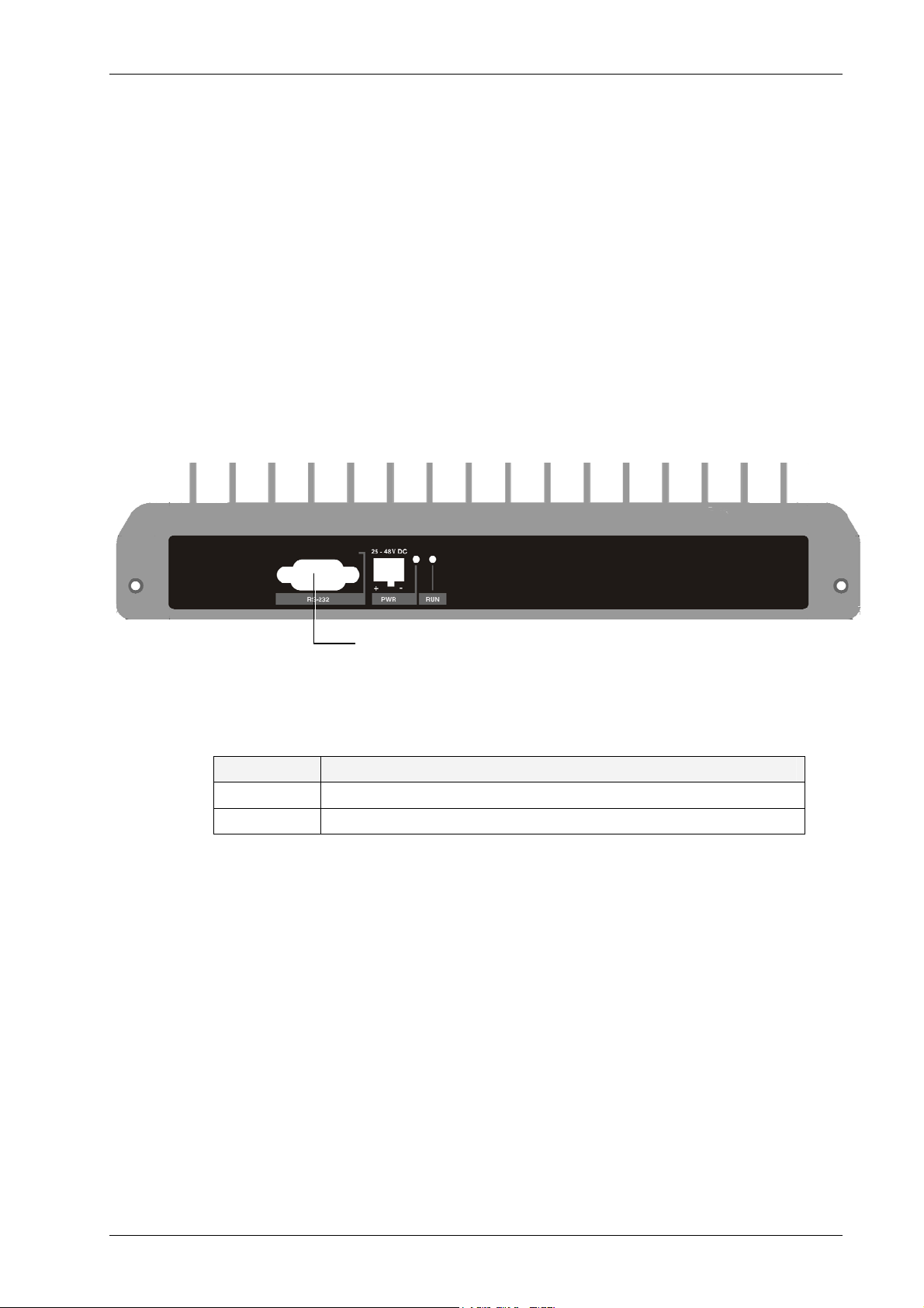
RHU 1200 Front Panel
The RHU 1200 front panel contains the power connection and status LEDs (the RS-232
connector is reserved for MA service personnel).
Service connector
Figure 4-7. RHU 1200 Front panels
Table 4-3. MobileAccess 1200 Front Panel Indicators
LED Description
RUN When blinking, indicates that the RHU is in normal operating mode.
PWR Power ON
Installation and Configuration Guide 31
Page 12

System Elements
LHig
RHU 1200 Rear Panel
The RHU 1200 rear panel contains the control connectors and the RF connections to the RU
2000 and MA 850.
h Band
D
Figure 4-8. RHU 1200 Rear Panel
Table 4-4. RU 1200 Rear Panel Connectors
UL
Add-on Control Transmits the control signals between the MA 1200 module and the
MA 850 and RU 2000 modules.
From – receives control signals from the RU 2000. Connected to
the RU 2000 Add-on Control connector.
DL, UL Transmit the RF signals to- and from- the MA 1200 add-on module.
These ports are connected to the corresponding ports on the MA
2000 rear panel: DL to DL, UL to UL.
High Service RF output port. Connected to combiner/splitter to be
combined with other services supported by the MA 2000 system.
Connections
1. Connect the power to the DC connector on the front panel.
2. Connect the MA 1200 From connector to the Add-on Control connector of the
corresponding MA 2000 RU.
3. Connect the High Band port to the Combiner connectors.
4. Connect the DL, UL connectors to the corresponding connectors on the MA 2000
module.
32 Installation and Configuration Guide
Page 13

System Elements
A
4.4.3 MA-850 Module
MobileAccess 850
provides a
secure
and
centralized
connection for 802.11a/b/g Access
Points. It significantly expands 802.11 coverage and enables distributing data and voice
services over the same coax and antenna infrastructure used by MA 2000 system.
MA 850 may be assembled on the MA 2000 cabinet top panel, or adjacent to the MA 2000
system (either Remote Cabinet or 2000 Lite configuration). It is integrated into the MA 2000
system by interconnecting the appropriate connectors. The combined signals of the MA 2000
system input to the MA 850 module and then distributed through the same coax broadband
antenna infrastructure
connected to the MA 850.
MA 850 may be remotely monitored through the RU 2000 system to which it is integrated,
and remotely configured through a point-to-point Ethernet connection.
The MA 850 front and rear panels, connectors and connections are described in detail in the
following sections.
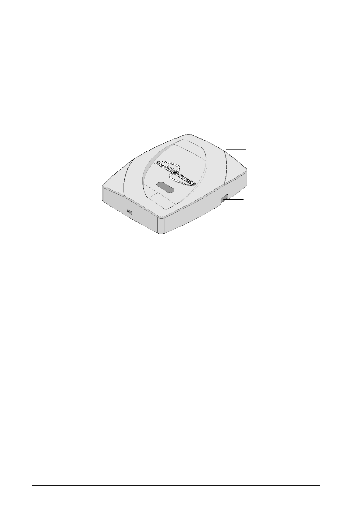
MA 850 Front Panel
The MA 850 front panel contains the antenna ports interfaces, local configuration interface
and power connection.
The following figure shows the MA 850 front panel.
Connections to corresponding
antenna ports of remote unit
ntenna ports
Power
Local RS232 connection
for configuration
Figure 4-9. MobileAccess 850 Front View
Table 4-5. MA 850 Front Panel Connections
Front Panel Description
Mobile Services Four SMA female connections to which the antenna port of the
MA 2000 system are connected.
To be terminated with 50 ohm terminations when not in use
Antenna Ports Four n-type female antenna connections
Local Local connection for setup
DC Power connection: 20V to 48V from a standard power supply
Installation and Configuration Guide 33
Page 14

System Elements
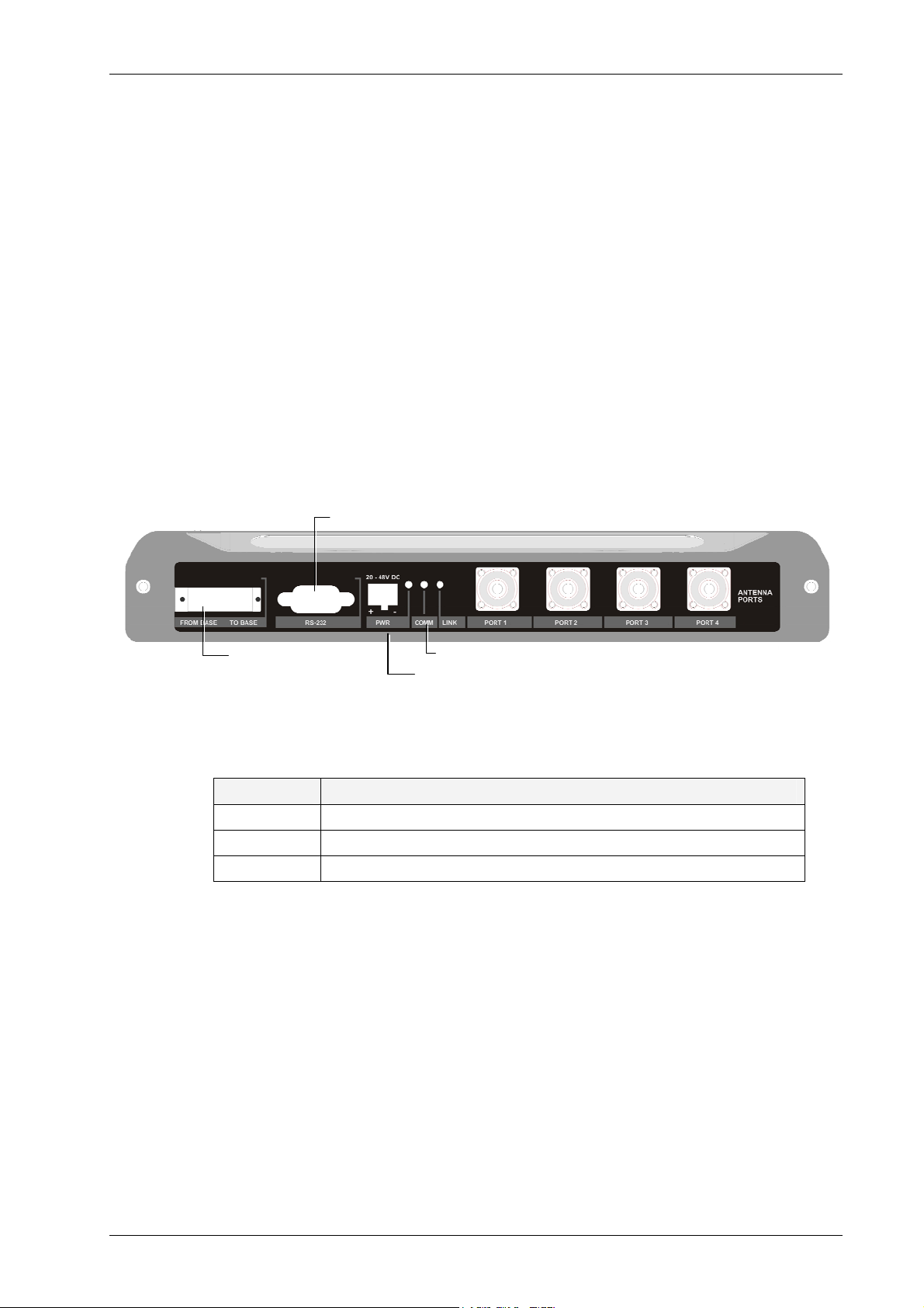
MA 850 Rear Panel
The MA 850 rear panel contains the connections to the APs, the Ethernet port for remote
configuration and the connection to the MA 1200 add-on control (if an MA 1200 add-on unit
is installed)
Connection to
add-on control
802.11 b/g APs
connections
Ethernet
Port
802.11 a APs
connections
Figure 4-10. MobileAccess 850 Rear View
Table 4-6. MA 850 Reart Panel Connections
Rear Panel Description
802.11b,g APs Connection to up to four 802.11b/g APs, where associated LED
Lite under the following conditions:
• Green: indicates where AP should be connected after
configuration
• Green flickering: Link with AP established but no data is
received
• Red: AP transmitting data
802.11a APs Connection to up to four 802.11a APs
Connection to
control
Connection to MA 1200 To connector on the rear panel. Used for
viewing antenna status
Ethernet port Connection to network for Web configuration
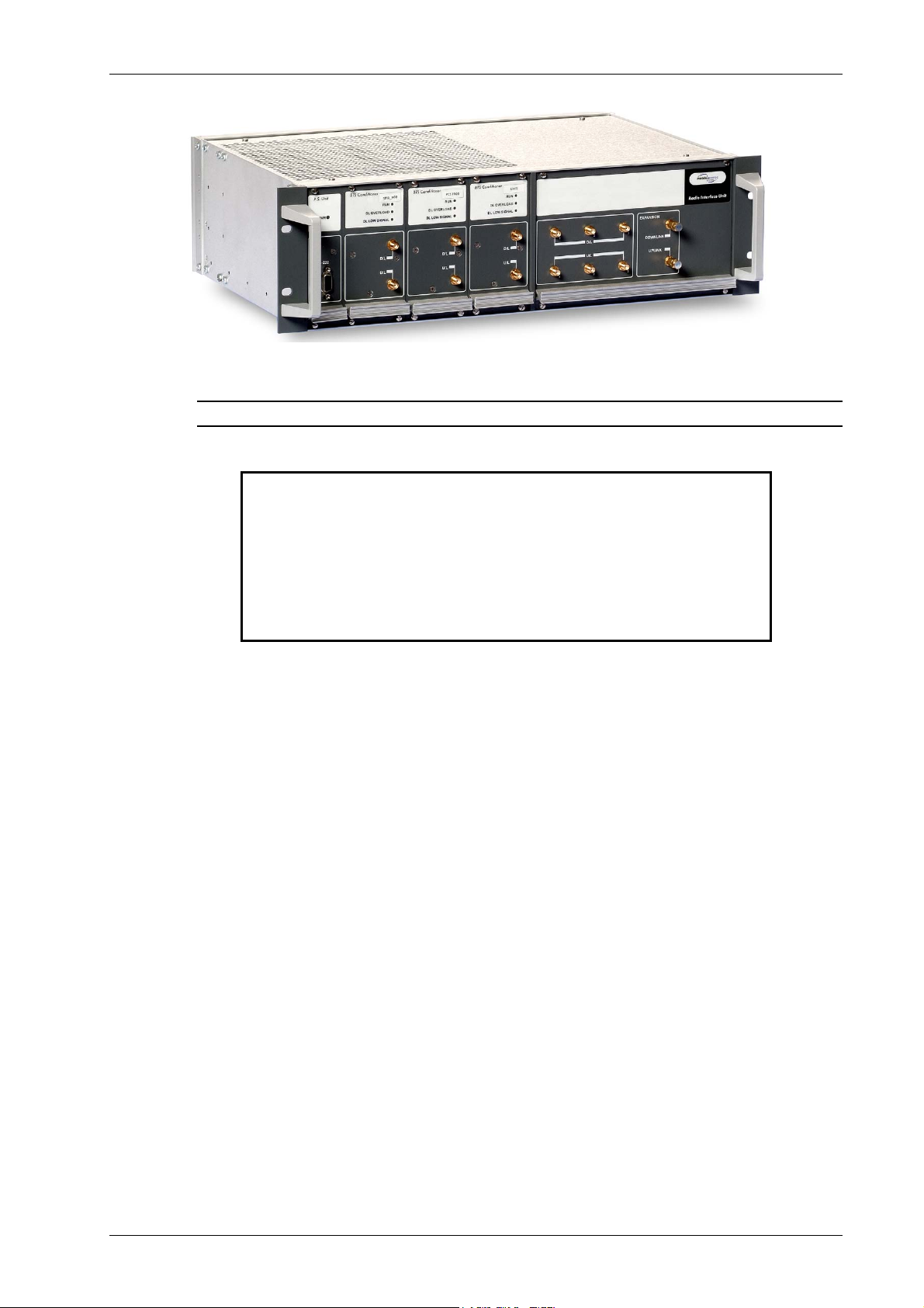
4.5 Radio Interface Unit (RIU)
The RIU is an operator dedicated unit that interfaces to up to three BTS sources and
automatically adjusts the signal output according to changing environmental conditions in
order to provide optimal coverage for the site. The RIU is remotely monitored and managed.
Each RIU can support up to three BTS Conditioner (BTSC) sub-modules, where each submodule provides interface to a BTS or BDA of
four
Each RIU can be connected to
8-port Base Units (real panel connections) or to
port Base Units.
Additional BUs can be supported by using splitters and combiners connected to the front
panel Expansion connectors.
The following figures shows an RIU with three BTSC sub-modules.
34 Installation and Configuration Guide
the same type of service
.
eight
4-
Page 15
System Elements
Figure 4-11. RIU
Note: All connections are via RG223 coax cables with 1/2" N-type male connectors
ATTENTION
1. The RIU is factory set to 0dB gain on the uplink and
downlink. In order to operate properly, an ADJUSTMENT
process is required in the field.
2. Any unused input and output connectors MUST be
terminated with 50 ohms – otherwise the ADJUSMENT
procedure results may be affected.
Installation and Configuration Guide 35
Page 16

System Elements
RIU Front Panel
The RIU front panel contains the indicators and expansion connectors for the connection of
additional BUs.
Power Supply
BTS Conditioners
Figure 4-12. RIU Front Panel
Table 4-7. RIU Front Panel Indicators
LED Description
P.S UNIT PWR ON – input signal is at the required level.
BTS CONDITIONER
RUN
BTS CONDITIONER DL
OVERLOAD
Flashing -- CPU is running and software loaded
Continuous Red – RF switch is disconnected to protect the system. This
may be due to:
• Unpredicted power rise for which the attenuation response was
insufficient to compensate and reduce the power to the required level.
• Software problem detected.
Flashing: When the BTSC DL output power is more than 3dB of the
calibrated value.
BTS CONDITIONER DL
LOW
Continuous Red – if the BTSC DL power is at least 15dB lower than the
calibrated BTSC max power level. This condition also triggers an event.
Expansion connectors - for
connecting additional BUs
36 Installation and Configuration Guide
Page 17
System Elements
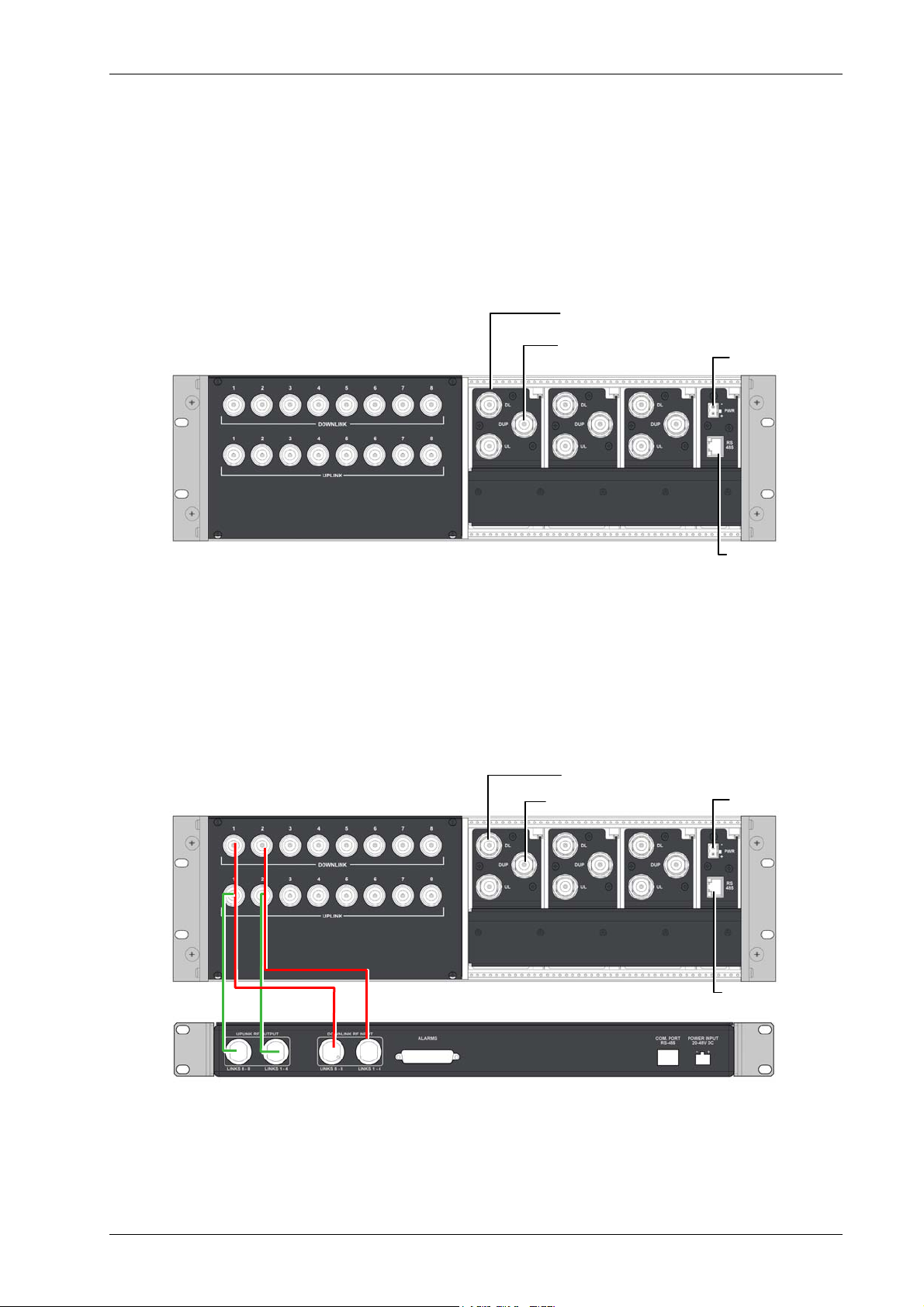
RIU Rear Panel
The rear-panel provides all the connections on the BTS side and on the BU side as well as
connections to the MobileAccess 410/430 controller and the power connection. Two types of
BTS side connections are available for each BTS conditioner: simplex and duplex.
BU connections; one UL and one DL
connection for every group of four ports
(single OPTM) on the BU.
BTS/BDA simplex
connections
BTS/BDA duplex
connections
Power connection
MA Controller connection
Figure 4-13. RIU Rear Panel showing the RF Connection
RIU Connections
1. Connect each BU to the corresponding RF Uplink and Downlink connectors on the
rear panel
RIU
to connect
used to connect an 8-port BU (two OPTMs).
. Note that
one OPTM
one uplink
and
one downlink
RIU rear-panel ports are used
(four ports from the BU); two uplink and two downlink ports are
MobileAccess 1000 BU
connections (pair per BU)
Figure 4-14. RIU Rear Panel showing the RF Connection
BTS/BDA simplex
BTS/BDA duplex
connections
connections
Power connection
Controller connection
Installation and Configuration Guide 37
Page 18
System Elements
NOTE: Up to four 8-port BU may be connected. Additional BUs may be connected
through the Extension connector on the front panel. Refer to section Connections to
Additional BUs, page 38.
2. Connect each BTS/BDA to the corresponding rear panel BTSC connectors. For each
BTSC connection, both simplex and duplex connections are available:
For a duplex connection, connect to the BTSC DUP port; •
• For a simplex connection, connect to the BTSC UL and DL ports;
3. Connect the Power connections on the RIU rear panel.
4. If your system includes a MA 410/430 controller, connect the RS485 port on the RIU
rear panel to the controller.
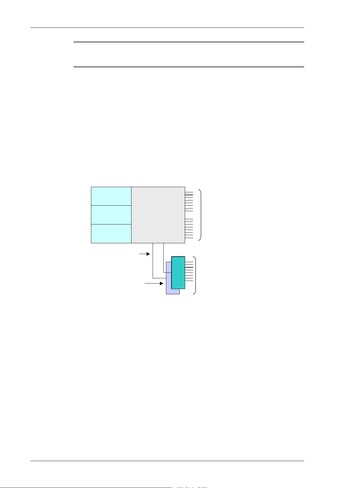
Connections to Additional BUs
To connect more than four 8-port BUs or more than eight 4-port BUs to the RIU, Connect an
8W splitter to the Downlink connector on the RIU front panel and an 8W combiner to the
Uplink connector on the RIU front panel and connect additional BUs to the uplink and
downlink connections.
BTSCBTSC
Combiners
BTSCBTSC
/Splitters
Compartment*
BTSCBTSC
Expansion ports
External 1:8 splitter
/combiner
4.6 MA Base Units
The BUs (Base Units) perform RF to optical conversion of the signal on the BTS/BDA side.
Each can support up to two services (provided by the same operator). Two models of MA
BUs are available: four-port unit – supporting four RUs, and eight-port unit supporting up to
eight RUs. The RU models correspond to the services supplied through the BUs.
UL and DL
connections to
four BU8 modules
UL and DL connections
to up to four additional
BU8 modules
The BU (and all the corresponding remote units) may be remotely monitored and managed
via the MA NMS (Network Management System).
The BUs are usually installed in the telecom room adjacent to the BTS/BDA signal source. RF
ports on the rear panel provide interface to the BTS side (through connection to RIU or
passive interface), while optic ports on the front panel provide interface to the RUs (Remote
Units).
This following sections describe the MA BU front and rear panels, including indicators and
connectors.
38 Installation and Configuration Guide
Page 19

System Elements
g
MA BU Front Panel
The front panel contains the optical connections and indicators. The BU is available in two
configurations: Four-port - and Eight-port BUs. The eight-port BU consists of two four-port
elements where each four-port element has a dedicated set of indicators (PWR, LSR and Link
1 to Link 4 or Link 5 to Link 8).
Four ports and corresponding indicators
Four ports and correspondin
indicators
Figure 4-15. Eight-Port MA BU Front Panel
Figure 4-16. Four-Port BU Front Panel
Table 4-8. MA BU Front Panel Indicators
LED Description
PWR Power input detected for the corresponding unit.
LSR ON - laser circuitry for the corresponding element (group of four ports) is
functioning correctly.
Link 1-4, 5-8 ON - the optical link to/from the connected remote functions within the
specifications in both directions.
Blinking - optical power from remote is lower than expected by at least 2dBm
Installation and Configuration Guide 39
Page 20

System Elements
A
BU Rear Panel
The BU rear panel contains the RF, Alarms, NMS and power connections. Note that there are
two uplink and two downlink RF connections to the BTS side (to an Interface Box or RIU) each individual uplink and downlink connection corresponds to a four-port BU element. For a
four-port BU, one uplink and one downlink port is connected; for an eight-port BU, two
uplink and two downlink ports are connected.
For systems that include MA 430 controllers, the RS 485 port is connected to the MA
410/430 controller to enable remote monitoring and management of the BU from a central
location. For systems without remote management, the Alarms dry-contact connector pins
can be connected to the BTS to provide alarms functionality.
Pair of uplink and downlink RF
connections for interface to BTS side.
Figure 4-17. MA BU Rear Panel (RF Connections)
Table 4-9. MobileAccess 1000 Rear Panel Connections
Connector Description
Uplink output Uplink connectors to be connected on BTS side.
Downlink input Downlink connectors to be connected on the BTS side.
Com Port RS485 Connection to MobileAccess 410/430 controller.
PWR Power connection
Alarms Dry-contact connections to BTS/BDA (normally closed).
BU connections
larms dry-contact
connector
MA 410/430 controller
Power
Relevant only for system without MA 410/430 controllers.
1. It is assumed that the patch panel cabinet (SC/APC adaptors) for fiber optic cable
connections is installed in the rack near the BUs.
2. Connect (3/125/900) pigtail with SC/APC connectors between splice tray and
patch panel cabinet.
3. Connect (3/125/3000) SC/APC jumpers between the corresponding BU and
patch panel.
4. Connect the fiber optic cables from the BU to the RUs through the patch
panel cabinet.
5. Connect the UL RF Output and DL RF Input connectors to the RIU or UL and
DL connectors or to the passive interface (such as Interface Box) in
topologies that do not include RIUs.
40 Installation and Configuration Guide
Page 21

System Elements
T
4.7 MobileAccess NMS System
NOTE This section provides general information on the MobileAccess 410/430 Controller. :
For detailed information on the controller, configuration and connections refer to the Mobile
Access NMS User
’
s Guide.
The MobileAccess controllers enable managing and controlling the MobileAccess system
elements. All the monitoring and control operations can be performed from the Master’s
location.
Two MobileAccess controller configurations are provided: MobileAccess 410 and MobileAccess
430. The models differ in their remote access capabilities:
• MobileAccess 410 provides point-to-point connectivity implemented via either direct
RS232 connection or via connection to a DSPN phone line
• MobileAccess 430 provides client/server management capability over TCP/IP network
with enhanced monitoring and control capabilities (in addition to the connectivity
options provided by MobileAccess 410).
NOTE The MobileAccess 430 front panel is differentiated from the MobileAccess 410 front :
panel by the SNMP Agent Card that provides TCP IP management capabilities. /
Controller Front Panel
Local RS232
connection (for IP
address setup)
Figure 4-18. MobileAccess 410 Front Panel
Major, Minor LED
indicators
Master/Slave configuration
CP/IP connection
Run and
Power LEDs
LCD alarm display
corresponding to Major and
Minor LEDs
Local RS232 connection to Laptop
(MA 300 for Remote controller)
Figure 4-19. MobileAccess 430 Front Panel
Installation and Configuration Guide 41
Page 22

System Elements
Controller Rear Panel
Note: The rear panels for the MobileAccess 410 and MobileAccess 430 are the same.
MA BU and RIU
inputs
Figure 4-20. MobileAccess 410/430 Rear Panel
BTS alarms output
General purpose
alarms input (MA 300).
Slave controller
connections
DC Input
42 Installation and Configuration Guide
Page 23

5
5
5.1 General
A
p
p
p
p
T
T
A
Two parameters are of prime importance when testing optical cables or jumpers for use with
Mobile Access products:
• Optical Loss – the difference between the optical power at the input and output of an
optical cable. It must be measured (usually in dB units) at 1310 nm. The maximum
allowable loss should be < 0.5 dB/km for Single Mode (SM) cables and < 0.5 dB for
every mated pair of connectors.
• Optical Backreflection – the percentage of light backreflected from the fiber input (dB
units). The maximum allowable backreflection should be < –55 dB for all jumper cables.
The methods to test these parameters will be described below.
e
e
e
e
n
dii
n
d
stt
s
x II::
x
Prr
P
o
o
O
c
c
O
e
e
pttii
p
d
urr
d
u
c
c
e
e
all
a
s
s
5.2 Optical Loss Testing of a Single Mode
Cable with SC/APC connectors at each
end
5.2.1 Required Test Equipment
• 1310 nm Stabilized Laser Source
• 1310 nm Optical Power Meter
• Two Fiber Optic Test Jumpers with SC/APC connectors at each end
• Two SC/APC Adapters
Installation and Configuration Guide 43
Page 24

Appendix I: Optical Test Procedures
5.2.2 Test Procedure
1. Set up the Laser Source, Optical Power Meter, and Test Jumper as shown below.
Figure 5-1. Set Up
2. Record reading as P1 in dBm units.
3. Serially connect the second Test Jumper as shown below.
Figure 5-2. Serial Connection of Second Jumper
4. Record the Power Meter Reading as P2 in dBm units.
5. Calculate Loss L12 according to the equation: L12 = P1 - P2
6. If L12 is lower than 0.5 dB continue to Step-7; otherwise replace these test cables and
repeat from Step-1.
44 Installation and Configuration Guide
Page 25

Appendix I: Optical Test Procedures
7. Disconnect connectors B and C. Connect the Cable Under Test (CUT) between
connector B and C as shown below.
8. Record Power Meter reading as Pcut in dBm units.
9. Calculate Cable Loss Ldut from the equation Lcut = P2- Pcut.
10. The maximum allowable loss should be < 0.5 dB/km for SM cables and < 0.5 dB for
every mated pair of connectors.
5.2.3 Example
Testing a 50 meter cable with SC/APC connectors at each end.
• P1 = -1dBm
• P2 = -1.5dBm
• L12= P1 – P2 = -1dBm - (-1.5) = 0.5 dB
Conclusion: the test cables are of sufficient quality to continue testing.
• Pcut = -2dBm
• Lcut = P2 - Pcut= -1.5dBm - (-2dBm) = 0.5 dB
This is acceptable since a mated connector pair was added along with the CUT and a loss of
-0.5 dB is allowed for every mated pair of connectors.
Figure 5-3. Connecting CUT
Installation and Configuration Guide 45
Page 26
Appendix I: Optical Test Procedures
5.3 Optical Backreflection Testing of SM
SC/APC connectors at each end of an
optical cable
5.3.1 Required Test Equipment
1. Adjustable1310 nm Stabilized Laser Source with output power greater than 7dBm.
2. 1310 nm Optical Power Meter with a measurement range of up to -70 dBm.
3. One low loss Singlemode 1310 nm 2x2 50%/50% Fiber Optic Coupler with SC/APC
connectors at all four fiber pigtailed ports. Pigtail length should be 50 cm.
4. One SC/APC Adapter
5.3.2 Test Procedure
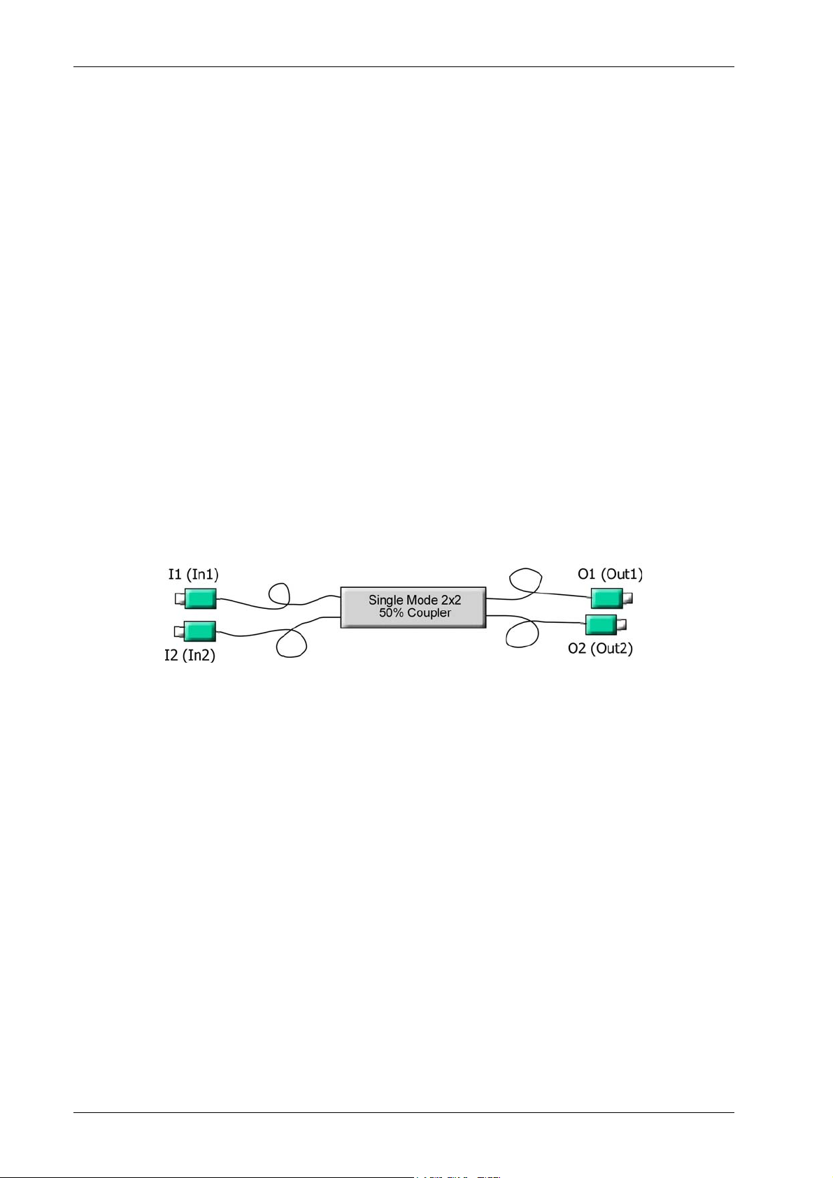
1. Refer to the following figure for port definitions of the Fiber Optic Coupler. The coupler is
symmetrical but for our purposes, each port should be identified as shown in Figure 1-4.
Figure 5-4. Port Identification
2. Measure the loss from port I1 to O1 according to the insertion loss method described in
the previous section. This loss will be referred to as LI1O1. It should be approximately
3.5 dB.
3. Measure the loss from port O1 to I2 in a similar manner. This loss will be referred to as
LO1I2. It should also be approximately 3.5 dB.
4. Calculate Total Loss, TL where TL= LI1O1 + LO1I2. TL should approximately 7dB.
5. Adjust the laser output power in dBm to the same value as TL.
For example, if TL = 7dB, adjust the laser output to 7 dBm.
46 Installation and Configuration Guide
Page 27
Appendix I: Optical Test Procedures
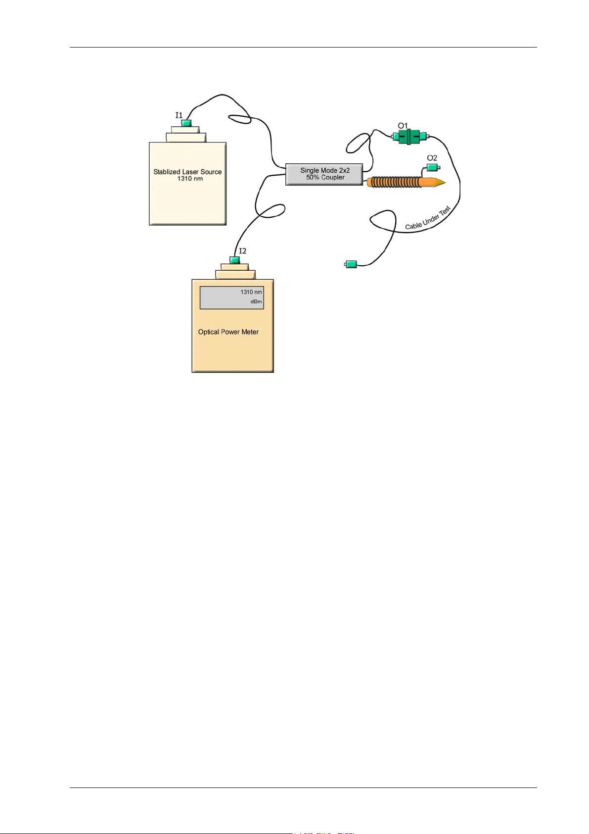
6. Connect the laser to port I1 of the coupler as shown in Figure 5-5.
Figure 5-5. Test Procedure Connections
7. Connect the Power Meter to port I2 of the coupler as shown in Figure 5-5.
8. Wrap the O2 pigtail around a pencil of diameter 7 to 8 mm as illustrated.
9. The power meter readings should be < –58 dBm; otherwise, clean connector O1 and
measure again.
10. Connect the cable under test to connector O1.
11. Record Power Meter Reading as Backreflection, BRcut, of the cable under test. The
power is measured in dBm units. This is the same value as the backreflection.
For example, if the power meter shows –58 dBm, the backreflection is –58 dB. The
maximum backreflection from the SC/APC connectors should be < –57 dB.
Long cables will have a higher BR since the cable itself reflects a small amount of light. This
small amount can grow to a considerable amount over a long length of fiber. To factor out
this cable backreflection, perform a mandrel wrap on the cable adjacent to the connector
under test and perform all measurements with the mandrel wrap.
Installation and Configuration Guide 47
 Loading...