

Page 1

Corning
Optical Communications
Corning CORE System MA2000
User Manual
P/N 709C006503 REV:A00 DATE: APRIL 2014
Page 2

Warranties
Hardware
Corning Optical Communications warrants to the original purchaser (“Customer”) that for the duration of the warranty period,
one (1) year, commencing on the date of shipment of the Hardware, unless otherwise agreed in writing by Corning
Optical Communications (the “Hardware Warranty Period”), the Hardware furnished by Corning Optical Communications shall
be free in all material respects from defects in material and workmanship, and shall conform to the applicable portions of the
Specifications, as defined below (the “Hardware Warranty”). If notified by Customer of any such defects in material or
workmanship or nonconformity with applicable portions of the Specifications within the Hardware Warranty Period, Corning
Optical Communications shall promptly, at its own election and expense, repair or replace any such Hardware proven to be
defective under the terms of this Hardware Warranty. Such repair or replacement shall be Customer’s sole remedy and
Corning Optical Communications’ sole obligation in the event this Hardware Warranty is invoked. If any components
comprising a part of the Hardware are replaced or repaired during the Hardware Warranty Period, the Hardware Warranty
Period for such repaired or replaced components shall extend to the longer of (i) the balance of the Hardware Warranty
Period or (ii) three (3) months from the date of repair or replacement. For purposes of this Warranty, “Specifications” shall
mean the specifications and performance standards of the Products as set forth in documents published by Corning Optical
Communications s and delivered to Customer which contain technical specifications or performance standards for the
Products.
If Customer invokes this Hardware Warranty, it shall notify Corning Optical Communications promptly of the claimed defect.
Customer will allow Corning Optical Communications to inspect the Hardware at Customer’s location, or to return the
Hardware to Corning Optical Communications’ closest repair facility. For Hardware returned to Corning Optical
Communications’ repair facility, Customer shall be responsible for payment of all transportation and freight costs (including
insurance) to Corning Optical Communications’ repair facility, and Corning Opt ical Com munications shall be responsible for
all transportation and freight costs (including insurance) incurred in connection with the shipment of such Hardware to other
repair facilities of Corning Optical Communications and/or its return to Customer.
Notwithstanding the foregoing, in no event will Corning Optical Communications be liable for damage to Products resulting
from improper handling during or after shipment, misuse, neglect, improper installation, operation or repair (other than by
authorized Corning Optica l Com munications personnel), alteration, accident, or for any other cause not attributable to defects
in materials or workmanship on the part of Corning Optical Communications. Corning Optical Communications shall not
reimburse or make any allowance to Customer for any labor charges incurred by Customer for replacement or repair of any
goods unless such charges are authorized in advance in writing by Corning Optical Communications.
Software Warranty
Corning Optical Communications warrants to the original purchaser (“Customer”) that for the duration of the warranty period,
one (1) year, commencing on the date of shipment of the Software, unless otherwise agreed in writing by Corning
Optical Communications (the “Software Warranty Period”), the Software shall conform with, and perform the functions set
forth in the Specifications, and shall be free from defects in material or workmanship (the “Software Warranty”). In the event
the Software is proven to be defective under the terms of this Software Warranty, Corning Optical Communications shall
correct such defects or failure and ensure that the Software conforms with, and performs the functions set forth in, the
Specifications. Customer will allow Corning Optical Communications to inspect the Software at Customer’s location or to
return it to Corning O ptic a l Com munications’ closest repair facility.
Notwithstanding the foregoing, Corning Optical Communications shall have no obligation under the Software Warranty if the
Software is modified or used with hardware or software not supplied or approved by Corning Optical Communications or if the
Software is subject to abuse, improper installation or application, accident, electrical or environmental over-stress, negligence
in use, storage, transportation or handling.
Third-party software distributed with the Software may carry certain warranties which, to the maximum extent allowed by law,
Corning Optical Communications s hereby assigns, transfers and otherwise conveys to Customer, provided, however, that
Warranties P/N 709C006503 Page 2
Page 3

Corning Optical Communications itself provides no warranty of any kind, express, implied, statutory or otherwise, for any
third-party software provided hereunder.
Corning Optical Communications does not warrant any hardware, software or services not provided by Corning Optical
Communications.
THIS WARRANTY IS THE ONLY WARRANTY MADE BY CORNING OPTICAL COMMUNICATIONS AND IS IN
LIEU OF ALL OTHER WARRANTIES, EXPRESS OR IMPLIED INCLUDING, BUT NOT LIMITED TO, THE IMPLIED
WARRANTIES OF MERCHANTABILITY AND FITNESS FOR A PARTICULAR PURPOSE. CORNING OPTICAL
COMMUNICATIONSS SHALL NOT BE LIABLE FOR ANY OTHER DAMAGE INCLUDING, BUT
NOT LIMITED TO, INDIRECT, SPECIAL OR CONSEQUENTIAL DAMAGES ARISING OUT OF OR
IN CONNECTION WITH FURNISHING OF GOODS, PARTS AND SERVICE HEREUNDER, OR THE
PERFORMANCE, USE OF, OR INABILITY TO USE THE GOODS, PARTS AND SERVICE.
CORNING OPTICAL COMMUNICATIONS SALES AGENTS OR REPRESENTATIVES ARE NOT AUTHORIZED TO
MAKE COMMITMENTS ON WARRANTY RETURNS.
Returns
In the event that it is necessary to return any product against above warranty, the following procedure shall be followed:
1. Return authorization is to be received from Corning Optical Communications prior to returning any unit. Advise Corning
Optical Communications of the model, Serial number, and discrepancy. The unit may then be forwarded to Corning
Optical Communications, transportation prepaid. Devices returned collect or without authorization may not be accepted.
2. Prior to repair, Corning Optical Communications will advis e t he customer of our test results and any charges for repairing
customer-caused problems or out-of-warranty conditions etc.
3. Repaired products are warranted for the balance of the original warranty period, or at least 90 days from date of shipment.
Limitations of Liabilities
Corning Optical Communications’ liability on any claim, of any kind, including negligence for any loss or damage arising from,
connected with, or resulting from the purchase order, contract, quotation, or from the performance or breach thereof, or from
the design, manufacture, sale, delivery, installation, inspection, oper at ion or use of any equipment covered by or furnished
under this contact, shall in no case exceed the purchase price of the device which gives rise to the claim.
Except as expressly provided herein, Corning Optical Comm unications makes no warranty, expressed or implied, with
respect to any goods, parts and services provided in connection with this agreement inclu ding, but not limited to, the implied
warranties of merchantability and fitness for a particular purpose. Corning Optic a l Com munications shall not be liable for any
other damage including, but not limited to, indirect, special or consequential damages arising out of or in connection with
furnishing of goods, parts and service hereunder, or the performance, use of, or inability to use the goods, parts and service.
Reporting Defects
Note: Keep all packing material until you have completed the inspection.
The units were inspected before shipment and found to be free of mechanical and electrical defects. Examine the units for
any damage that may have been caused in transit. If damage is discovered, file a claim with the freight carrier immediately.
Notify Corning Optical Communications as soon as possible in writing.
Warranties P/N 709C006503 Page 3
Page 4

Warnings and Admonishments
There may be situations, particularly for workplace environments near high-powered RF sources, where recommended limits
for safe exposure of human beings to RF energy could be exceeded. In such cases, restrictive measures or actions may be
necessary to ensure the safe use of RF energy.
The equipment has been designed and constructed to prevent, as far as reasonably, practicable danger. Any work activity on
or near equipment involving installation, operation or maintenance must be, as far as reasonably, free from danger.
Where there is a risk of damage to electrical systems involving adverse weather, extreme temperatures, wet, corrosive or
dirty conditions, flammable or explosive atmospheres, the system must be suitably installed to prevent danger.
Equipment provided for the purpose of protecting individuals from electrical risk must be suitable for the purpose and properly
maintained and used. This covers a range of activities inclu di ng lifting, lowering, pushing, pulling, carrying, moving, holding or
restraining an object, animal or person from the equipment. It also covers activities that require the use of force or effort, such
as pulling a lever, or operating power tools.
Where some of the abovementioned activities are required, the equipment must be handled with care to avoid being
damaged.
Observe standard precautions for handling ESD-sensitive devices. Assume that all solid-state electro nic devices are ESDsensitive. Ensure the use of a grounded wrist strap or equivalent while working with ESD-sensitive devices. Transport, store,
and handle ESD-sensitive devices in static-safe environments.
RF Safet y
WARNING! To comply with FCC RF exposure compliance requirements, each individual antenna used for this product must
be fixed mounted in indoor permanent structures, providing a separation distance greater than 50 cm or more from all
persons during normal operation and must not be co-located with any other antenna for meeting RF exposure requirements.
The design of the antenna installation needs to be implemented in such a way so as to ensure RF radiation safety levels and
non-environmental poll uti o n during operation.
WARNING! Antenna gain should not exceed 12.5 dBi.
WARNING! The design of the antenna installation needs to be implemented in such a way so as to ensure RF radiation
safety levels and non-environmental pollution during operation.
Compliance with RF safety requirements:
• Corning Optical Communications products have no inherent significant RF radiation.
• The RF level on the downlink is very low at the downlink ports. Therefore, there is no dangerous RF radiation when the
antenna is not connected.
Power requirements for DC Inputs
WARNING! Only use a special DC supply cable with four connectors
WARNING! Always keep DC IN connectors connected during the product operation
WARNING! Disconnect all power from the equipment by means of an external circuit breaker before connecting or
disconnecting the DC IN connectors.
Warnings and Admonishments P/N 709C006503 Page 4
Page 5

Laser Safety
CAUTION!
Fiber optic ports of the MA2K system elements emit invisible laser radiation at the 1310/1550 nm wavelength window.
The laser apertures /outputs are the green SC/APC Bulkhead adapters located on the front panel of the equipment.
The product is Class 1/Hazard level 1
External optical power is less than 10 mW, Internal optical power is less than 500 mW.
To avoid eye injury never look directly into the optical ports, patchcords or optical cables. Do not stare into beam or view
directly with optical instruments. Always assume that optical outputs are on.
Only technicians familiar with fiber optic safety practices and procedures should perform optical fiber connections and
disconnections of MA2K devices and the associated cables.
Corning CORE System MA2000 has been tested and certified as a Class 1 Laser product to IEC/EN 60825-1 (2007). It also
meets the requirements for a Hazard Level 1 laser product to IEC/EN 60825-2: 2004 to the same degree.
Corning CORE System MA2000 system complies with 21 CFR 1040.10 and 1040.11 except for deviations pursuant to Laser
Notice NO. 50 (2007).
Care of Fiber Optic Connectors
Do not remove the protective covers on the fiber optic connectors until a connection is ready to be made. Do not leave
connectors uncovered when not connected.
The tip of the fiber optic connector should not come into contact with any object or dust.
Refer to the cleaning procedure for information on the cleaning of the fiber tip.
USE OF CONTROLS OR ADJUSTMENTS OR PERFORMANCE OF PROCEDURES OTHER THAN
THOSE SPECIFIED HEREIN MAY RESULT IN HAZARDOUS RADIATION EXPOSURE
Regulatory Compliance I nformation
WARNINGS!
• This is NOT a CONSUMER device. It is designed for installation by FCC LICENCEES and QUALIFIED INSTALLERS.
You
MUST have an FCC LICEN SE or express consent of an FCC Licensee to operate this device. Unauthorized use
may result in significant forfeiture penalties, including penalties in excess of $100,000 for each continuing violation.
ANTENNAS: Use only authorized and approved antennas, cables and/or coupling devices! The use of unapproved
•
antennas, cables or coupling devices could cause damage and may be of violation of FCC regulations. The use of
unapproved antennas, cables and/or coupling devices is illegal under FCC regulations and may subject the user to fines.
Laser Safety P/N 709C006503 Page 5
Page 6

Standards and Certifications
US
Warning!
Changes or modifications to this equipment not expressly approved by Corning Mobile Access could void the
user’s authority to operate the equipment.
Europe
NTRL Safety
Laser Safety
TRA
Corning Optical Communications products have met the approvals of the following certifying organizations:
Company Certification
ISO 9001: 2000 and ISO 13485: 2003
Product Certification
Radio Equipment and Systems
• FCC 47 CFR part 22 – for CELL Frequency Band
• FCC 47 CFR part 24 – for PCS Frequency Band
• FCC 47 CFR part 27 – for LTE and AWS Frequency Bands
• FCC CFR part 15 Subpart B
• FCC CFR part 90
Note: This equipment has been tested and found to comply with the limits for a Class A digital device, pursuant
to Part 15 of the FCC Rules. These limits are designed to provide reasonable protection against harmful
interference in a residential installation. This equipment generates, uses and can radiate radio frequency
energy and, if not installed and used in accordance with the instructions, may cause harmful interference to
radio or television reception, which can be determined by turning the equipment off and on, the user is
encouraged to try to correct the interference by one or more of the following measures:
- Reorient or relocate the receiving antenna.
- Increase the separation between the equipment and receiver.
-Connect the equipment into an outlet on a circuit different from that to which the receiver is connected.
-Consult the dealer or an experienced radio/TV technician for help.
Radio Equipment and Systems
• EN 301502 – for GSM/EGSM Frequency Bands
• EN 300609 – for DCS Frequency Bands
• EN 301908 – for UMTS Frequency Band
EMC
EN 301 489
UL 60950-1
IEC 60825-1, IEC 60825-2
TRA type approval for UAE
Licensee Contact Informat ion
Industrial Boosters may only be used by FCC licensees or those given express (individualized) consent of license. Corning
Corning Optical Communications certifies all of the VARs listed as licensed installers for CMA. For the list of licensed VARs,
please contact the CMA Tech Support Hotline: (US) 410-553-2086 or 800-787-1266.
Standards and Certifications P/N 709C006503 Page 6
Page 7

About this User Manual
Document Name
Acronym
Description
BDA
BDAC
BTS
BTSC
BU
DL
LOS
PS
RHU
RU
RIU
SC-450
UL
This user guide describes how to perform the physical installation of the Corning CORE System MA2000. The installation
procedures of other units (e.g. RIU, MA850/MA860, LTE) relevant to the system are detailed in their user manuals (see
‘Additional Relevant Documentation’ below).
Additional Relevant Documents
The following documents are required if the corresponding units are included in your system.
MA850/MA860 Installation and Configuration Guide
MobileAccess2000 700/800 Public Safety RHU Quick Start Guide
MobileAccess1000 / MobileAccess2000 User Manual Add end um
for 700 MHz LTE Solution
RIU Installation and Configuratio n Gu ide
SC-450 Installation and Configuration Guide
NMS MA 410/430 Installation and Configuration Guide
MA1000 MA2000 Commissioning Guide
MA Software Version Update Tool
List of Acronyms
Bi-Directional Amplifier
Bi-Directional Amplifier Conditioner
Base Transceiver Station
Base Transceiver Station Conditioner
Base Unit
Downlink
Line of Sight
Power Supply
Remote Hub Unit
Remote Unit
Radio Interface Unit
System Controller
Uplink
About this User Manual P/N 709C006503 Page 7
Page 8

Table of Contents
Warranties ................................................................................................................................. 2
Hardware ....................................................................................................................................................... 2
Software Warranty ........................................................................................................................................ 2
Returns .......................................................................................................................................................... 3
Limitations of Liabilities ................................................................................................................................. 3
Reporting Defects ......................................................................................................................................... 3
Warnings and Admonishments................................................................................................ 4
RF Safety ................................................................................................................................... 4
Compliance with RF safety requirements: .................................................................................................... 4
Power requirements for DC Inputs .......................................................................................... 4
Laser Safety .............................................................................................................................. 5
Care of Fiber Optic Connectors .................................................................................................................... 5
Regulatory Compliance Information ........................................................................................ 5
Standards and Certifications ................................................................................................... 6
Company Certification ................................................................................................................................... 6
Product Certification ...................................................................................................................................... 6
Licensee Contact Information .................................................................................................. 6
About this User Manual ............................................................................................................ 7
Additional Relevant Documents .................................................................................................................... 7
List of Acronyms ....................................................................................................................... 7
Table of Contents ...................................................................................................................... 8
1 Introduction ...................................................................................................................... 11
1.1 Features and Capabilities ................................................................................................................... 11
1.2 MA2000 System Architecture .............................................................................................................. 12
1.2.1 Headend Equipment ................................................................................................................. 13
1.2.2 Remote-End Equipment ............................................................................................................ 13
1.3 Application Examples .......................................................................................................................... 14
1.4 System Monitoring and Managem ent ................................................................................................. 16
2 MA2000 System Elements ............................................................................................... 17
2.1 Enclosure Types.................................................................................................................................. 17
2.1.1 MA2000 MRC............................................................................................................................ 17
Table of Contents P/N 709C006801 Page 8
Page 9

2.1.2 MA2000 - Lite ............................................................................................................................ 20
2.2 MA2000 Remote Location Units ......................................................................................................... 21
2.2.1 MA2000 RU............................................................................................................................... 21
2.2.1.1 MA2000 RU Front Panel .............................................................................................. 22
2.2.1.2 MA2000 RU Rear Panel .............................................................................................. 23
2.2.2 MA1200 Add-on ........................................................................................................................ 23
2.2.2.1 MA1200 Front Panel .................................................................................................... 24
2.2.2.2 MA1200 Rear Panel .................................................................................................... 25
2.2.3 8 x 4 Combiner .......................................................................................................................... 26
2.2.3.1 MA 8x4 Combiner Front Panel .................................................................................... 26
2.2.3.2 MA 8x4 Rear Panel ...................................................................................................... 27
2.3 MA Base Unit ...................................................................................................................................... 27
2.3.1 Base Unit Models ...................................................................................................................... 27
2.3.2 BU Panels ................................................................................................................................. 28
2.3.2.1 MA BU Front Panel ...................................................................................................... 28
2.3.2.2 BU Rear Panel ............................................................................................................. 29
3 Installation Guidelines ..................................................................................................... 30
3.1 Site Considerations ............................................................................................................................. 30
3.2 Infrastructure Preparation ................................................................................................................... 30
3.3 Environmental ..................................................................................................................................... 30
3.4 Installation Requirements .................................................................................................................... 30
3.5 Coaxial Cable Connections ................................................................................................................. 31
3.5.1 General Cable Installation Procedures ..................................................................................... 31
3.5.2 Cable Routing ........................................................................................................................... 31
3.6 Fiber Optic Requirements ................................................................................................................... 31
3.6.1 Authorized Optic Cables ........................................................................................................... 31
3.6.2 Fiber Optic Rules ...................................................................................................................... 32
3.7 RF Rules ............................................................................................................................................. 32
3.8 Coax Cable Lengths and Losses ........................................................................................................ 33
3.9 Antenna Specifications and Guidelines .............................................................................................. 34
3.9.1 Authorized Antennas and Required Specifications................................................................... 34
3.9.2 General Antenna Installation Guidelines .................................................................................. 34
3.10 Grounding Requirement ...................................................................................................................... 34
3.11 Manual Handling ................................................................................................................................. 34
3.12 Power Consumption, Connections and Power Supp lie s .................................................................... 35
3.12.1 Power Safety Instructions ......................................................................................................... 35
3.12.2 Power Consumption of Units .................................................................................................... 35
3.12.3 Cir cuit Br eak er s ........................................................................................................................ 35
3.12.4 Types of Power Supplies .......................................................................................................... 35
3.13 Installation Conventions ...................................................................................................................... 36
4 System Installation .......................................................................................................... 37
4.1 Pre-installation Instruc ti ons ................................................................................................................. 37
4.1.1 Unpacking and Inspection ......................................................................................................... 37
4.2 Communication Room Installation ...................................................................................................... 37
Table of Contents P/N 709C006802 Page 9
Page 10

4.2.1 Rack Installation General Instructions ...................................................................................... 37
4.2.2 MA2000 MRC Wall Mount Installation ...................................................................................... 41
4.2.3 MRC Grounding - Integrated PS Wall Mount Model ................................................................. 43
4.2.4 MRC 2000 Rack Mount Installation .......................................................................................... 44
4.2.5 Fiber Optic Connections ........................................................................................................... 45
4.2.6 Power Connections ................................................................................................................... 45
4.2.6.1 Integrated Power Supply model................................................................................... 45
4.2.7 Antenna Connections ................................................................................................................ 46
4.3 MA2000-Lite Installation and Connections ......................................................................................... 46
4.3.1 Mounting MA2000-Lite .............................................................................................................. 48
4.3.2 MA2000-Lite Connections ......................................................................................................... 49
5 Upgrading and Configuration Examples ........................................................................ 50
5.1 Common USA Configurations ............................................................................................................. 50
5.1.1 iDEN/SMR wit h PC S Add -on .................................................................................................... 50
5.1.2 Cell/PCSH ................................................................................................................................. 52
5.1.2.1 Cell/PCSH and LTE 700 .............................................................................................. 52
5.2 AWS Add-On ....................................................................................................................................... 53
5.3 Public Safety 700/80 0 ......................................................................................................................... 53
5.4 Typical International Configurations .................................................................................................... 54
5.4.1 Typical Asian Configuration: Cell/DCS+ UMTS ........................................................................ 54
5.4.2 Typical European & Midd le East Conf igur at io n: EG SM/DCS + UMTS Configuration .............. 54
Appendix A : System Specifications ..................................................................................... 56
RF Parameters ............................................................................................................................................ 56
RF Frequency Range .......................................................................................................................... 56
Low Band ............................................................................................................................................ 57
High Band ............................................................................................................................................ 58
RF Parameters MA1200 Add-on ......................................................................................................... 59
System Specs ............................................................................................................................................. 60
Fiber Optic Specifications ................................................................................................................... 60
Absolute Maximum Rating .................................................................................................................. 60
Temperature Specifications ................................................................................................................ 60
Specifications of Units ................................................................................................................................. 61
MA 2000 MRC Remote Hub ............................................................................................................... 61
MA 2000 Lite ....................................................................................................................................... 61
MA 2000 Remote Unit ......................................................................................................................... 61
MA 1200 Add-On Specif ic ations ......................................................................................................... 61
Base unit Specifications ...................................................................................................................... 62
Appendix B: Ordering Information ........................................................................................ 63
Table of Contents P/N 709C006802 Page 10
Page 11
1 Introduction
Corning CORE S ystem MA2000 series provides enterprise level indoor cover a ge, of a wide r ang e of m ulti -op erator wire less
services over a single broadba nd infrastructure. Front-end wireless RF services are routed, over optic fibers, to MA2000
series hubs that are securely located in the telecommunication closets at each remote location. These modular service
aggregation platforms precisely combine multiple wireless service signals for simultaneous distribution over a common
broadband infrastructure.
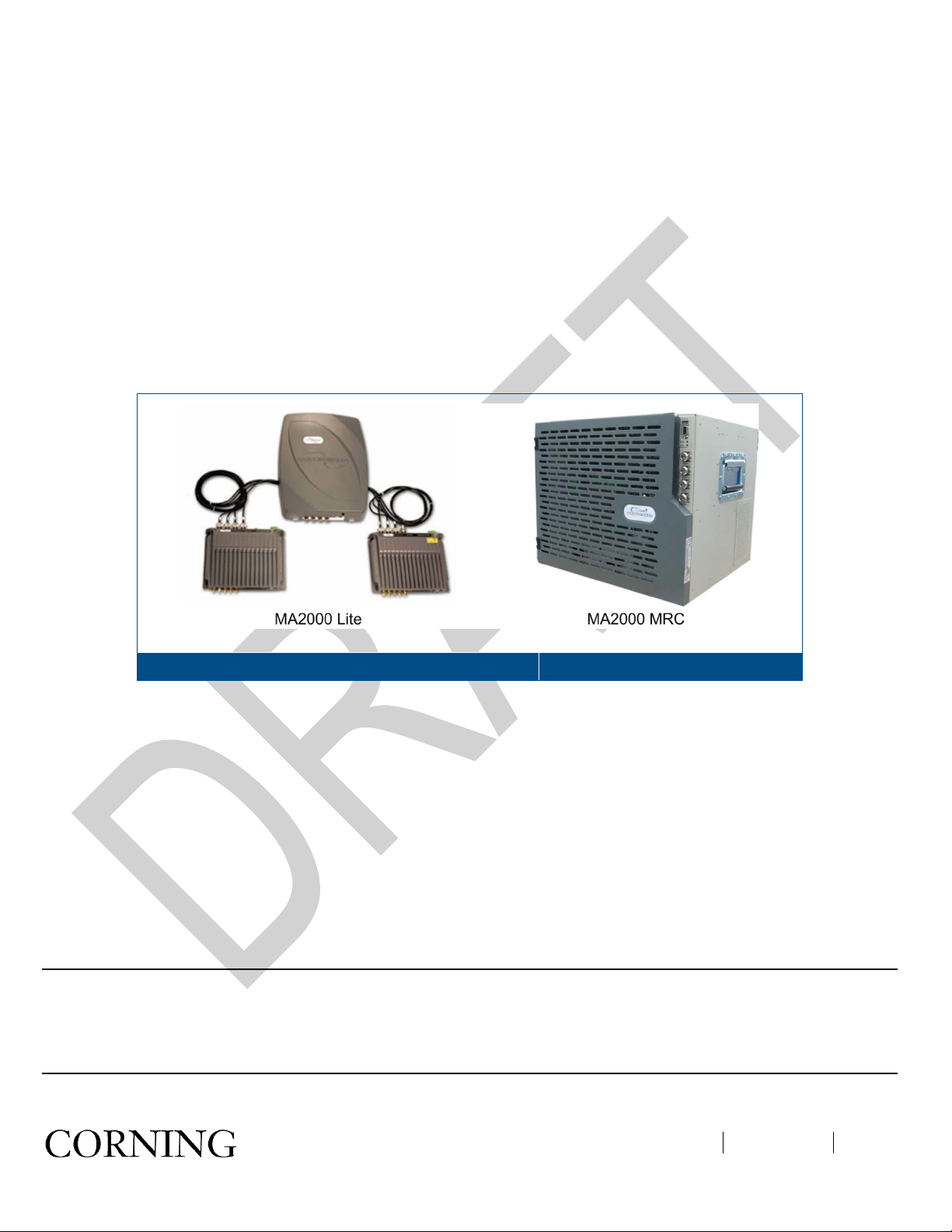
Two remote service hub models are available:
•
MA2000-Lite – supports two remote units that are connected externally, where MA1200 Add-Ons and MA85 0/M A86 0
units can be integrated with the remote units.
•
MA2000 Cabinet (MRC) – internally houses a total of five remote units and MA1200 add-on units with which
MA850/MA860 can be integrated as an external assembly.
MA2000-Lite (left side) and MA2000 Cabinet (right side)
Figure 1-1
1.1 Features and Capabilities
• Multi-service platform that accommodates virtually any combination of wireless voice and data services eliminating the
need for separate overlay networks
• Scalable and future-safe – services can be added and removed without affecting existing operators or end-users
• MA2000-Lite components can be migrated to MA2000 MRC for increased capacity
• All active components are located in the communication closet/room
• Carrier class operation – MA2000 advanced signal handling ensures optimal performance for all services within a multi-
operator deployment
• Local and remote end-to-end monitoring and control through interface to SC-450 controller
• Conditioning and monitoring of input RF signals at the head-end through interface to MA-RIU
Note: Corning Opt ical Com munications has made the t r ansiti on to ‘2000M’ pr od uct s that s up por t b oth s i ng le mode fiber and
multimode fiber. The new Base Unit is des ignate d b y W BM (Wide Band M), an d the new RUs (Rem ote Un its) are indicated
as ‘2000M’ RUs, where t he suffix “M” indica tes that the product will support bot h single mode and m ultimode fiber us age
The new products have th e same packaging and perform ance and are fully backward compatible. Se e
multimode fiber use.
3.6 for details o n
.
Introduction P/N 709C006503 Page 11
Page 12
1.2 MA2000 System Architecture
The MA2000 solution com prises bot h headend and rem ote end e quipment providing an end-to-end comprehensi ve system
solution.
Note: Third-party equipment is sold separately (i.e. cabling, antennas).
At the head-end C orning CORE System elements provide interface t o the wireless service provider’s network , where the
signals can be conditioned through an active interface and transported over optic fiber to the remote end.
At the remote end, the o ptical signal is reconverted t o RF, amplified, filtered an d distributed over t he broadband antenna
infrastructure.
For end-to-end control, controllers ins talled at the hea d-end provid e direct interf ace to the MA elem ents and thr ough them ,
control over the remote end elements.
MA2000 System Architecture
Figure 1-2 shows a basic block diagram of the system operation. On the downlink, services from the BTS/BDA are
transferred via interfac e to the Base Un its (BUs ). T he interfac e, which m a y be passive (i.e. Interf ace Box ) or act ive (RIU) , is
used to attenuate the RF signals to the required levels, converge them and distribute them to the BUs. The BUs
wideband – they are not service specific.
At the BUs, the RF signals are c onverted to optical signals and transmitted over the opt ic fiber to (service-specific) RUs at
the remote locations. At the r emote locations, the RUs suppor ted by the hub (MRC or Lite) reconvert th e optical signal to
RF. The hub elements converg e the voice services together with 802.11 a/b/g data services (if MA850/M A860 units are
installed) and distribute them over the coax antenna infrastructure. The MA SC-450 (in installations with remote
management) provides monitoring and control of all active system elements.
Introduction P/N 709C006503 Page 12
Figure 1-2
are
Page 13

1.2.1 Headend Equipment
At the headend Corning CO RE System elements provide interface to t he wireless service provider’s network, where the
signals can be conditioned through an active interface and transported over optic fiber to the remote end.
Radio Interface Unit (RIU): The RIU conditions the RF Downlink (DL) signals from an operator’s signal source (BTS:
•
base-transceiver stations or BDA: bi-directional amplifiers) located inside the building. The RIU then custom tunes
incoming signals in order to ensure a constant level of RF before signals are passed to/from the Base Unit (BU). RF
Uplink (UL) signals from subscribers’ phones are received from the BU and transported back to the operator’s signal
source (BTS or BDA) and to the operator’s macro network outdoors.
•
Base Unit (BU): The BU converts RF Downlink (DL) signals received from the RIU into an optical signal. This optical
signal is then transported over single or multi-mode fiber optic cabling (SMF/MMF) to/from the MA2000 TSX units,
which are housed inside of IDF/Telc o/IT closets at the remote-end locations, for distribution throughout the facility.
Uplink (UL) signals from subscribers’ phones are received from the antennas and sent back to the TSX units through
the fiber connection to the head-end, where they are converted back from RF optical to RF electrical before being
passed on to the RIU.
•
System Controller (SC-450): The system controller enables centralized remote management and control of all Corning
CORE System MA2000 elements.
1.2.2 Remote-End Equipment
The remote end elem ents interface to the DAS infrastructure. At the r emote end, the optical signal is reconver ted to RF,
amplified, filtered and distributed over the broadband antenna infrastructure.
Remote Units (RUs) – Pre-configured service specific modules that support up to two voice services and perform the
•
optic to RF conversion on signals received from the BU at the remote locations. Signals are automatically filtered and
amplified for transport over broadband coax cable to a passive antenna. Uplink (UL) signals from the antennas are then
converted to optical signals before being transmitted back to the BU.
• MA1200 Add-On – Service specific module that provides support for an additional high band voice service. The AO is a
single service module coupled with an RHU to deliver an additional, third service at a lower incremental cost. The AO
receives RF signal from the RHU and amplifies it for transport across the broadband coax.
•
MA850/MA860 – Module that supports data services
Introduction P/N 709C006503 Page 13
Page 14
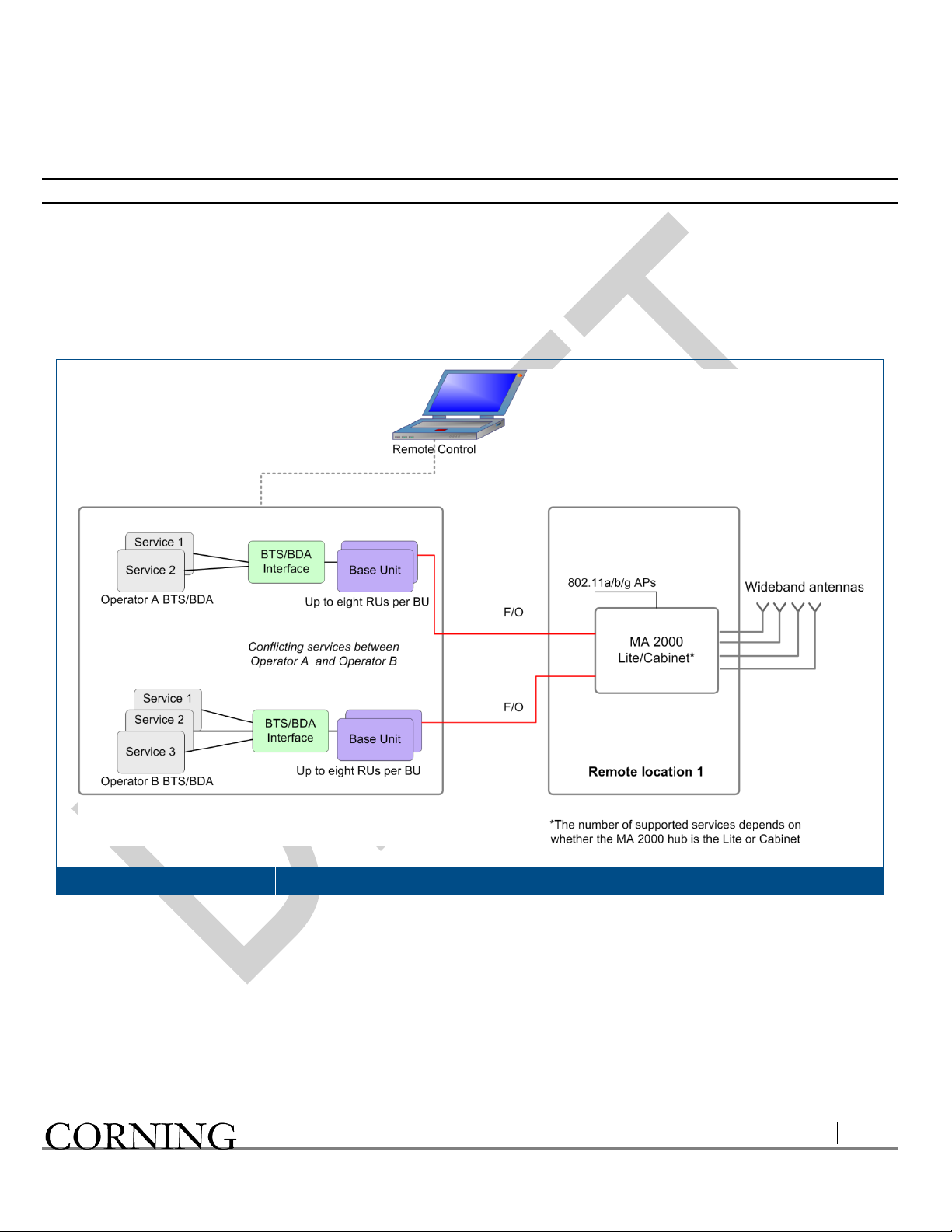
1.3 Application Examples
Figure 1-3 shows an example of an MA2000 Cabinet based solution. Five services from two different operators are
distributed, where services from Operator A conflict with those from Operator B.
The converted optical sign a l is r outed f r om the BUs dir ec tl y to the corresponding R Us in each Ca bin et o ver o ptic f iber . Each
BU supports connections to 8 RHUs. Additional BUs are required for connection to more RUs.
Services 1 and 2 are distri buted through one of the RHUs supported in each Cabi net. Services 3, 4 and 5 are distributed
through the second RU and the MA1200 unit connected to that RU.
MA850 and MA860 converge 802.11a/b/g data services with the voice services to be distributed through a common
infrastructure of coax and wideband antennas.
Example of MA2000 Cabinet Architecture
Introduction P/N 709C006503 Page 14
Figure 1-3
Page 15

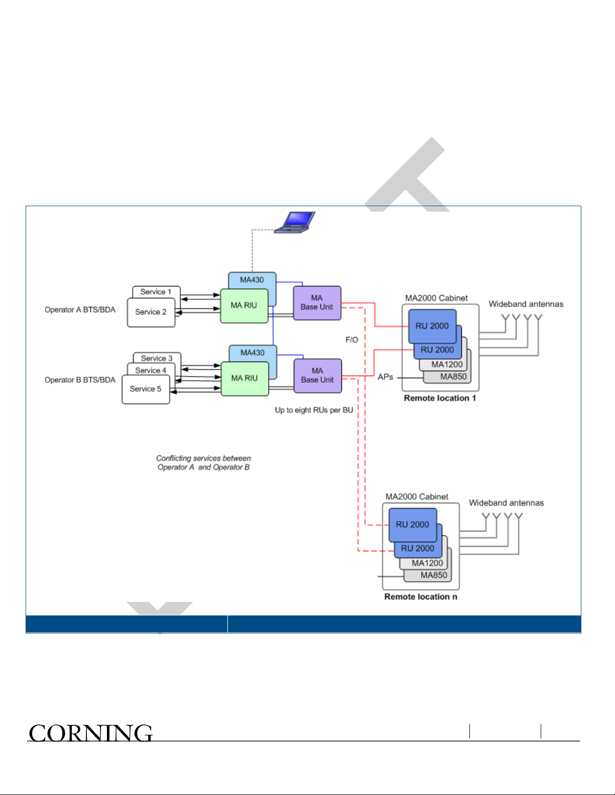
Figure 1-4 shows an exam ple of an MA2000-Lite based solution. Four services from two different operators are distributed.
The converted optical signal is routed from the BUs directly to the corresponding RUs over optic fiber.
Services 1 and 2 are distributed through one of the RUs supported by MA2000-Lite. Services 3 and 4 are distributed
through the second RU. The combiner and filter provides interface to the antennas.
Example of MA2000-Lite Architecture
Figure 1-4
Introduction P/N 709C006503 Page 15
Page 16
1.4 System Monitori ng and Management
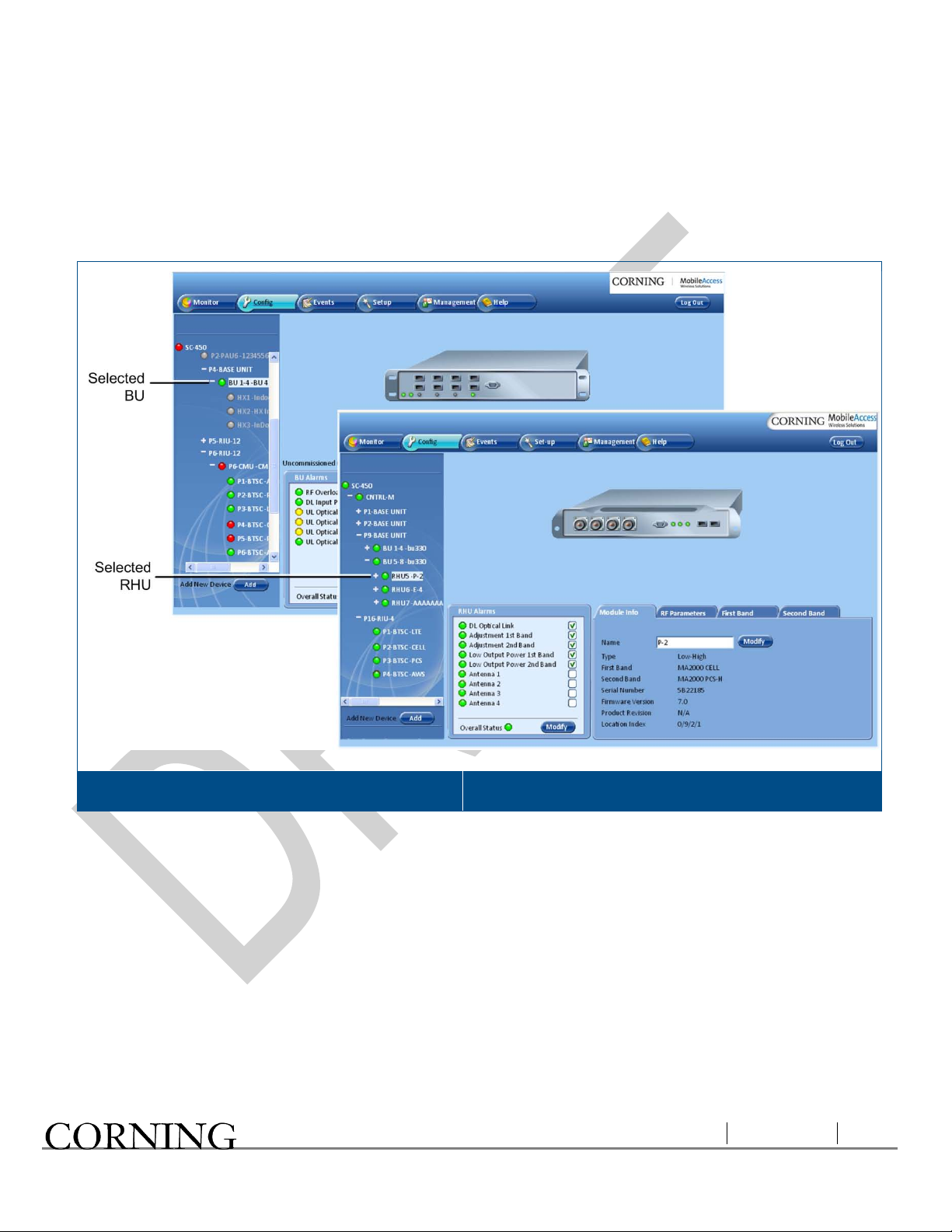
The MA2000 system elements are centrally manage d via the CORE SC-450 Control ler. The elements are displayed i n a
hierarchal corresponding to their physical connections in the topology tree of the Management GUI.
The following shows t he Configuration tabs of the selected BU and RHU. Refer to the SC-450 Controller User Manual for
information on how to configure and manage MA2000 elements .
Example of MA2000 BU and RHU Configuration Tabs
Introduction P/N 709C006503 Page 16
Figure 1-5
Page 17
2 MA2000 System Elements
This chapter provides a full, detailed description of each of the system elements and their individual connections. The
element descriptions are organized according to the following sections:
• Enclosures types – MRC (MA2000 Remote Cab in et) and Lit e
• Remote Location Elements:
• MA2000 Remote Units (RUs)
• MA1200 Add-on
• Base Unit
Note: The following elem ents are fully described in their corresponding user guides: MA RIU, MA 850 /MA860, SC-450
Controller, MCT/NMS Management Application (described in MA410/MA430 Installation and Configuration Guide).
2.1 Enclosure Types
This section describes both types of enclosures (MRC/Lite) and their external connections.
2.1.1 MA2000 MRC
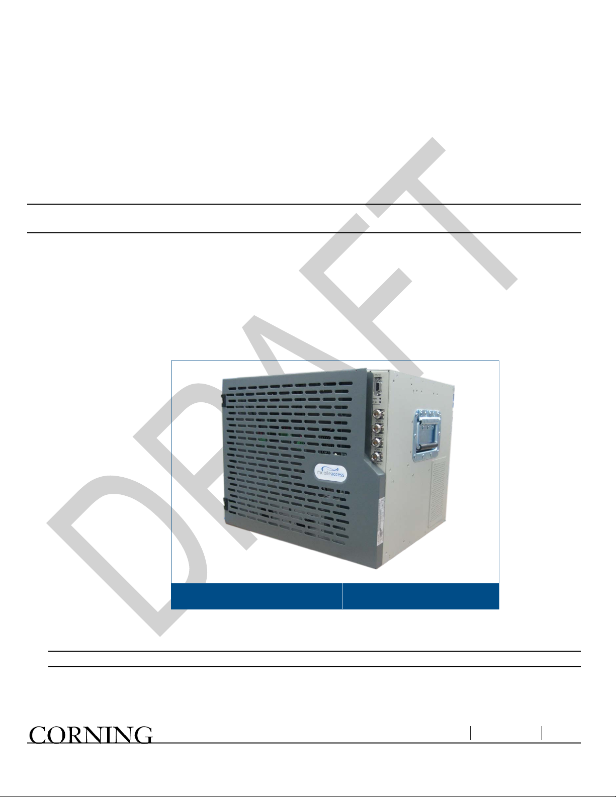
MA2000 MRC Closed Cabinet View
MA2000 Cabinet supports the following functions:
• Compactly houses up to five MA2000 RHU and MA1200 modules and the required filters
Figure 2-1
Note: The number of modules that can be housed depends on the models, required filtering, etc.
• MA850/MA860 can be connected externally
• Converges all voice services and provides a single interface to the antennas through external connections
• Wall mounted or rack mounted
MA2000 System Elements P/N 709C006503 Page 17
Page 18
• Supplied in two models with differing power supply:
• Integrated power supply – fed from an external AC power source. The MA2000 RHU an MA1200 Add-on modules
are internally connected to the power supply. This model includes a battery connection as well.
• External power supplies – power is routed to external connectors from which power is routed internally to each
MA2000 RHU and MA1200 Add-On module
Open door views
Figure 2-2 s ho ws a n op en MA2000 MRC c a bin et, inte grated power supply model , w ith f our MA2000 RHU modules an d f our
filters. (For clarity, the internal connections are demonstrated separately in Figure
2-3).
MA2000 MRC Open Cabinet View (without Internal Connections)
MA2000 System Elements P/N 709C006503 Page 18
Figure 2-2
Page 19
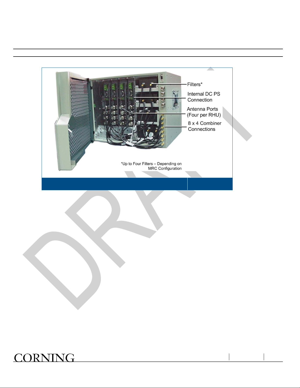
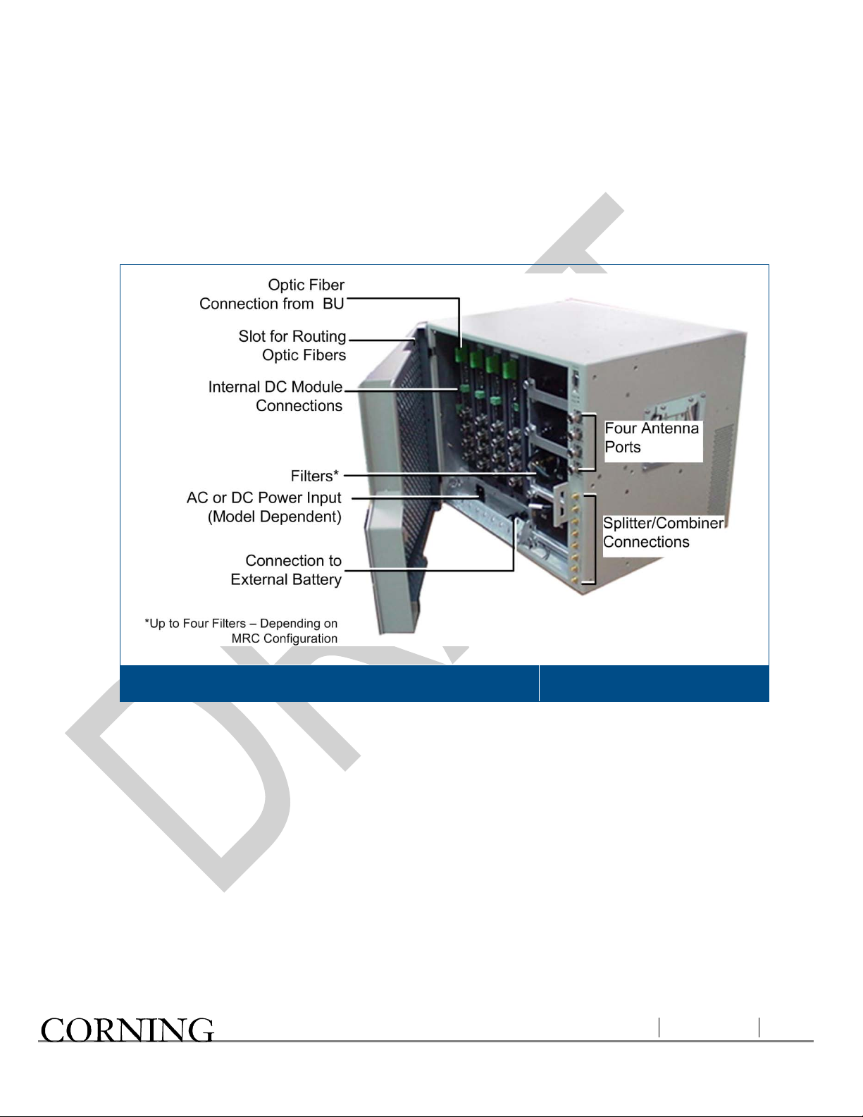
Figure 2-3 shows the MA2000 MRC with the cabling. The antenna ports of the individual modules are c onnected to the
relevant filters and to the 8 x 4 Combiner. The PS connections of each module are also connected to cables that are
internally routed to the integrated PS (a full detailed description of the connections is provided in chapter
The fiber optic connections are not displayed.
Note:
5).
MA2000 MRC Open Cabinet View (without Internal Connections)
Figure 2-3
MA2000 System Elements P/N 709C006503 Page 19
Page 20
2.1.2 MA2000 - Lite
Cable Connector
Description
Connector
Description
LEDs
Description
The MA2000-Lite is designed to support up to 8 voice services, in addition to 802.11 data services.
MA2000-Lite System
Figure 2-4
MA2000-Lite capabilities:
• External connections to two MA2000 RHUs (to which MA1200 Add-on units can be added)
• Internal filters and combiner (converges all services)
• Connection to MA850/MA860 for support of 802.11a/b/g data services
• External power supplies
The MA2000 enclosure contains two sets of cables, each providing connections to two MA2000 RUs.
Four N-type connectors Coax connections to corresponding antennas
1x DB-9 connector Connection to RU front panel RS232 connector
The following table describes the MA2000-Lite front panel connectors.
Ant-1 to Ant-4 (N-type) Coax connections to corresponding antennas
Control Control connector for MA service personnel.
Power 20 to 48V DC power input
The following table describes the front panel LEDs.
Run Module is operating properly.
Power Green – required power is suppl ied .
MA2000 System Elements P/N 709C006503 Page 20
Page 21

2.2 MA2000 Remote Location Units
Service specific units loca ted at each remote locatio n convert the optical s ignals received fr om the Base Units to RF signals
and route them to the coax antenna infrastructure.
The voice services are converged by an 8x4 Combiner unit that is installed in the Cabinet enclosure and the Lite
Note:
module.
The following types of service specific elements are available:
• Remote Units (RUs) – support two voice services
• MA1200 Add-On – adds an additional (third) voice service to the host RU to which it is connected.
• MA850/MA860 – converges data services from 802.11a/b/g APs and distributes them over the same coax and antenna
infrastructure
Note: The MA850/MA860 is described in detail in the MA850/MA860 Configuration and Installation guide.
2.2.1 MA2000 RU
MA2000 RU is a service specific module that is either housed in th e M A20 00 Ca b inet or connected externall y to the M A2000Lite module.
It provides the following functions:
• Performs the optic to RF (and vice versa) conversion at the remote locations
• Supports two services – high-band and low-band
• Interfaces to the optic fiber from the BU
• Add-On ready – MA1200 can be added to support an additional services
• Remote management - requires connection of host BU connection to an SC-450 controller
Note: MA2000 also supports management via MA410/MA430 controllers.
MA2000 System Elements P/N 709C006503 Page 21
Page 22

2.2.1.1 MA2000 RU Front Panel
LED
Description
The MA2000 RU front pan el contains the fiber optic connecti ons to the BU, four coax connectio ns to the antennas, power
connections and status indicators.
MA2000 RU Front Panel
0 Front Panel Indicators
COMM Active communication detected
LINK Optical link to BU detected
PWR DC power connection.
Figure 2-5
20 to 48VDC
MA2000 System Elements P/N 709C006503 Page 22
Page 23

2.2.1.2 MA2000 RU Rear Panel
Add-on control:
Add-on Control
From
DL, UL:
The MA2000 RU rear panel provides the co ntro l, RF interf ace an d optic int erfac e ports th at enable c onnec ting t o an MA1200
Add-On unit.
MA2000 RHU Rear Panel
Transmits the control signals from MA1200 Add-On module to the
MA2000 RU module. The
MA1200 Add-On
Transmit the RF signals to- and from- the MA1200 Add-On module.
These ports are connected to the corresponding ports on the MA1200
rear panel: DL to DL, UL to UL.
Figure 2-6
port is connected to the
port.
2.2.2 MA1200 Add-on
The MA1200 Add-On module is used to pro vide support for an additional serv ice to an MA 200 0 RU. The host MA 2000 RU
and the MA1200 Add-On are int erconnected and either housed in a MA2000 Cabin et or connected ex ternally to a M A2000Lite ‘enclosure’.
MA1200 Add-On provides the following functions:
• Single service – either low-band or high-band
• Installed only as an addition to a MA2000 RU
Note: MA1200 Add-on does NOT interface directly to the fiber optic infrastructure, does not perform the optic to RF
conversion and does not interface to the antennas. All these functions are provided by the host MA2000 RU unit.
MA2000 System Elements P/N 709C006503 Page 23
Page 24

2.2.2.1 MA1200 Front Panel
LED
Description
LED
Description
The MA1200 f ront pane l contains the power c onnectio n and status LEDs. (The RS-232 connector is r eserved f or MA service
personnel). The figure below shows the MA 1200 front view. It is followed by a description of the connections and LEDs.
MA2000 1200 AO Front Panel
Table 2-1. MA1200 Front Panel Connectors
RS232 Servicing connector to be used by MA service personnel for maintenance.
PWR DC Power connection.
25 to 48VDC
Table 2-2. MA1200 Front Panel LEDsndicators
RUN When blinking, indicates that the RU is in normal operating mode.
PWR Power ON
Figure 2-7
MA2000 System Elements P/N 709C006503 Page 24
Page 25

2.2.2.2 MA1200 Rear Panel
Add-on Control:
From –
Add-on Control
To
DL, UL:
High:
The MA1200 rear panel contains the control connectors and the RF connections to the MA2000 RU and MA850/MA860.
MA2000 1200 AO Rear Panel
Table 2-3. MA1200 Rear Panel Connectors
Transmits the control signals between the MA1200 module and
the MA850/MA860 and MA2000 RU modules.
Connected to the MA2000 RU
– feeds control signals to MA850/MA860 (in configurations
that include MA850/MA860)
Transmit the RF signals to- and from- the MA1200 add-on
module. These ports are connected to the corresponding ports
on the MA 2000 rear panel: DL to DL, UL to UL.
Service RF output port. Connected to combiner/splitter to be
combined with other services supported by the MA2000 system.
Figure 2-8
receives control signals from the MA2000 RU.
connector.
MA2000 System Elements P/N 709C006503 Page 25
Page 26

2.2.3 8 x 4 Combiner
Connector
Description
Ant-1 to Ant-4 (N-type)
Connections to corresponding antennas
Setup
Future Option
Note: This unit is internal to the MA2000 system – both Cabinet and Lite models.
This unit is installed in the MA2 000 system Cabinet and MA 2000-Lite enclosures . It combines the RF outputs of the RUs in
the corresponding system and provides a common interface to the coax antenna infrastructure.
The 8x4 Combiner provides the following capabilities:
• Supports up to eight RF voice service connections: four high-band and four low-band
• Supports four antenna interface ports (located externally on the MA2000-Lite)
• Provides low RF loss and high isolation for the input devices
2.2.3.1 MA 8x4 Combiner Front Panel
The front panel of the unit contains the four antenna interface ports, LEDs and control port.
8 x 4 Combiner Front Panel
2-4 describes the front panel connectors.
Table
Table
2-4. 8 x 4 Front Panel Interfaces
Figure 2-9
MA2000 System Elements P/N 709C006503 Page 26
Page 27

2.2.3.2 MA 8x4 Rear Panel
SMA Connectors
Description
Low Band
Four connectors (ports 1-4) for the low-band outputs of the corresponding remote
Control
Interfaces to the Digital card (that enables antenna monitoring)
The rear panel of the unit contains four low-band and four high-band ports as well as the control port.
8 x 4 Combiner Rear Panel
Table 2-5 describes the 8 x 4 rear panel connectors.
2-5. 8 x 4 Combiner Rear Panel Connectors
Table
unit. Refer to Chapter 5 for the connections relevant to each configuration.
High Band Four connectors (ports 5-8) for the high-band outputs of the corresponding remote
unit. Refer to Chapter
Figure 2-10
5 for the connections relevant to each configuration.
2.3 MA Base Unit
The BU (Base U nit) is a wideband de vice that performs the conversion bet ween the BTS/BDA (pas sive or active) interf ace
RF signal and the remote units’ optic signal.
Base Unit capabilities
• Supports all services distributed by Corning CORE Systems
• Fiber connection to up to 8 RUs
• Setup and monitoring through connection to the host SC-450 controller and NMS software application
• Dry contact alarms
• Front panel indicators providing status on optical link internal circuitry and signal level
2.3.1 Base Unit Models
Two models of MA BUs are available:
• B4U - four port unit comprising one optical module supporting optic connections to up to four RHUs
• B8U – eight port unit comprising two optical modules supporting optic connections to up to eight RHUs
Each optical module is separately accessed and managed in the MCT and NMS management applications.
Note:
MA2000 System Elements P/N 709C006503 Page 27
Page 28

2.3.2 BU Panels
LED
Description
2.3.2.1 MA BU Front Panel
The front panel contains the optical connections and indic ators. Each four-port element has a dedicated set of indicators
(PWR, LSR and Link 1 to Link 4 or Link 5 to Link 8).
B4U and B8U Front Panels
Table 2-6. MA BU Front Panel Indicators
PWR Power input detected for the corresponding unit.
20 to 48VDC
LSR
Link 1-4, 5-8
ON - laser circuitry for the corresponding element (group of four ports) is
functioning correctly.
ON - the optical link to/from the connected remote functions within the
specifications in both directions.
Blinking - optical power from remote is lower than required
Figure 2-11
MA2000 System Elements P/N 709C006503 Page 28
Page 29

2.3.2.2 BU Rear Panel
Connector
Description
The BU rear panel contains the RF connections, Alarms, NMS and power connections.
Note: Figure
2-12 shows the rear panel of an 8-port BU. A 4-port BU contains a single UL and a single DL RF connector.
B8U Rear Panel
Figure 2-12
Table 2-7. MA BU Rear Panel Connections
Uplink output
Uplink connectors to be connected on BTS/BDA side. For an 8-port BU, both UL connectors
must be connected.
Downlink input
Downlink connectors to be connected on the BTS/BDA side. For an 8-port BU, both DL
connectors must be connected.
Com Port
Connection to SC-450 controller, rear panel RS485 port.
RS485
Alarms
Dry-contact connections to BTS/BDA (normally closed). Relevant only for system without SC450 controller.
PWR Power connection: 20 to 48VDC
MA2000 System Elements P/N 709C006503 Page 29
Page 30

3 Installation Guidelines
This following installation rules are based on the assumption that site survey and installation planning (including power
requirements) have been completed.
3.1 Site Consider ations
• The distance between the service antenna and the coverage area should correspond to LOS requirements for maximum
coverage area.
• The maximum fiber path loss is 6 dB.
• The system delay of the optical system must be taken into consideration when there are neighboring BTS sites
overlapping in coverage.
3.2 Infrastructure Preparati on
The infrastructure preparation consists of two main phases:
A.
Floor Planning: Planning the distribution of the antennas on each floor to provide the required coverage.
B.
Telecom Closet Planning: Planning the layout of the devices and cables in the telecom closet or shaft. This includes the
MA850/MA860, 802.11 Access Points, cabling and other voice service distribution systems that are relevant to the specific
installation.
3.3 Environmenta l
Humidity has an advers e effect on the reliability of the equipm ent. It is recommended to install the equ ipment in locations
having stable temperature and unrestricted air-flow.
The installation location for the system should be well ventilated. The equipment has been designed to operate at the
temperature range and humidity level as stated in the product specifications with a relative humidity of max. 90% and
temperatures ranging as follows:
Operating: 0 to 50
Storage: -20°C to 85°C (-4°F to 185°F)
o
C (-4° to 185°F)
3.4 Installation Requirements
• Mounting surface shall be capable of supporting the weight of the equipment.
• In order to avoid electromagnetic interference, a proper mounting location must be selected to minimize interference from
electromagnetic sources such as large electrical equipment.
• Working space available for installation and maintenance for each mounting arrangement. Ensure unrestricted airflow.
• Ensure grounding connector is within reach of the ground wire.
• Ensure a power source is within reach of the power cord and the power source has sufficient capacity.
• Where appropriate, ensure unused RF connectors are terminated.
• Do not locate the equipment near large transformers or motors that may cause electromagnetic interference.
• Reduce signal loss in feeder cable by minimizing the length and number of RF connections.
• Ensure the equipment will be operated within the stated environment (refer to datasheet).
• Where appropriate, confirm available of suitably terminated grade of RF and optical fiber.
• Observe handling of all cables to prevent damage.
Installation Guidelines P/N 709C006503 Page 30
Page 31

3.5 Coaxial Cable Connections
3.5.1 General Cable Installation Procedures
Note: The installer should be familiar with the ANSI/TIA/EIS-568 Cabling Standard gui del in es.
Observe the general cable installation proc edures that m eet with the building c odes in your ar ea. The building c ode requires
that all cabling b e installed abov e ceiling level (where applicabl e). The length of cable fr om the risers to ea ch antenna m ust
be concealed above the ceiling.
The cable must be properly su pported and maintained straight using velcro cable ties, cable trays and clamps or hanger s
every 10 feet (where practical above ceiling level). Where this is not practical, the following should be observed:
• The minimum bending radius of the supplied ½” coax cable should be 7”.
• Cable that is kinked or has a bending radius smaller than 7” must be replaced.
• Cable runs that span less than two floors should be secured to suitably located mechanical structures.
• The cables should be supported only from the building structure.
• All cables shall be weather-resistant type
• Cable length - determined by the system installation plan. When calculating the cable length, take into account excess
cable slack so as not to limit the insertion paths.
3.5.2 Cable Routing
.
Ensure all cables, e.g. power cable, feeder cable, optic fiber, commissioning cable, connecting are properly routed and
secured so that they are not damaged.
3.6 Fiber Optic Req ui rements
3.6.1 Authorized Optic Cables
• Either single mode or multimode fiber can be used with Corning CORE 2000M products , whil e MA2000 products can
only be used with single mode fiber.
• Only Multimode fiber, 50/125 or 62.5/125um complying with ANSI/TIA/EIA-568-B series, EN50173-1 or ISO/IEC 11801
can be used. The fiber length can be up to 300 meters assuming the following qualifications:
• All fiber in a given length of fiber must be of the same core diameter.
• All Bulkhead adapters must be Single mode SC APC (Green) adapters.
• All terminations, cross connections or patches must be direct fusion splice or Corning Optical Communications specified
patch cords according to the listed below:
900 microns patchcord for splicing, 2 Meters, 2 x SC APC
Diamond p/n ENC/1045341 Beige boots, 62.5/125/900
Diamond p/n ENC/1045340 Black boots, 50/125/900
Zipcord patchcord, 4 x SC APC, 50/125/900/2000/4500 micron
Diamond p/n ENC/1045342 Black/Brown boots, 1Meter
MA# 500001057
MA# 500001058
MA# 50000105
Diamond p/n ENC/1045343 Black/Brown boots, 3 Meter
Zipcord patchcord, 4 x SC APC, 62.5/125/900/2000/4500 micron
Installation Guidelines P/N 709C006503 Page 31
MA# 500001060
Page 32

Diamond p/n ENC/1045344 Beige/Brown boots, 1 Meter MA# 500001061
Diamond p/n ENC/1045345 Beige/Brown boots, 3 Meter MA# 500001062
3.6.2 Fiber Optic Rules
ATTENTION!
Please also refer to the Laser Safety section in the document Preface.
• Use only 8-degree SC/APC connectors (green color).
• Use only fusion splice for connecting two fibers.
• Fiber optic cables require proper handling. Do not stretch, puncture, or crush the fiber cable(s) with staples, heavy
equipment, doors, etc.
• Always maintain the minimum bending radius specified by the cable manufacturer. The minimum bend radius is usually
10 times the cable's outer diameter. In the case of single optical fiber that is not in a cable, the minimum bending radius
to be observed is 30 mm.
• Pay special attention w hile c onnec ti ng the SC APC connectors - ensure that you hear a “click”, indicating a secure
connection
• Use minimum splicing/connectors to achieve minimum losses on the fibers.
• Use precaution while installing, bending, or connecting fiber optic cables.
• Use an optical power meter and OTDR for checking the fiber optic cables.
• Make sure the environment is clean while connecting/splicing fiber optic cables.
• All fiber optic connectors should be cleaned prior to connecting to the system
• Fiber connector protective caps should be installed on all non-terminated fibers and removed just before they are
terminated.
• Check the fiber optic connections.
• Never look directly into the end of a fiber that may be carrying laser light. Laser light can be invisible and can damage
your eyes.
3.7 RF Rules
• Use coax RG223, 50ohm, male-to-male N-type for RF connections from the BUs to the BTS/RBS and to the RIU.
• When using the Corning CORE System in an environment in which other indoor coverage systems are installed, it is
recommended (where possible) that the antennas are placed at least two meters apart
• When bending coax cables, verify that the bending radius does not exceed the coax specifications.
• Use wideband antennas supporting a range of 800 MHz to 2500 MHz
• Use a VSWR meter (i.e. Site Master or equivalent) for checking coax cables, including the antennas. (<2). The VSWR
must be measured prior to terminating the RUs in the remote communication rooms
• Terminate all unused RHU, AO and RIU ports with a 50 ohm load
• Make sure that the VSWR measured at the coax cable meets the product specification. The VSWR must be measured
prior to terminating the RHU RF ports in the remote communication rooms.
Installation Guidelines P/N 709C006503 Page 32
Page 33

3.8 Coax Cable Lengths and Losses
Coax Length
Coax Loss
(900 MHz)
Connector
Loss
Total Loss
Use coax ½”, 50ohm, male-to-male N-type, for connecting to RHU and antenna ports.
The required distance between the antennas (installed in the ceiling) depends on the infrastructure and calculated path-
Note:
loss. For example, if ther e is free space-loss between the antennas, a minimum distance of 100 ft is required; if there are
partitions (loss) between the antennas, a distance of less than 100 ft between them is allowed.
Table 3-1. Typical Coax Cable Lengths and Losses
30 0.7 1.5 2.2
40 0.9 1.5 2.4
50 1.1 1.5 2.6
60 1.3 1.5 2.8
70 1.5 1.5 3
80 1.7 1.5 3.2
90 1.9 1.5 3.4
100 2.1 1.5 3.6
110 2.3 1.5 3.8
120 2.5 1.5 4
130 2.7 1.5 4.2
140 2.9 1.5 4.4
150 3.1 1.5 4.6
160 3.3 1.5 4.8
170 3.5 1.5 5
180 3.7 1.5 5.2
190 3.9 1.5 5.4
200 4.1 1.5 5.6
Installation Guidelines P/N 709C006503 Page 33
Page 34

3.9 Antenna Specifications and Guidelin es
Determine the antenna installation configuration, according to the transmission and coverage requirements and the
installation site conditions.
3.9.1 Authorized Antennas and Required Specifications
External antennas - No limitation on any vendor of available external antennas with respect to the following requirements:
• Omni Directional or Directional
• Supported frequency range: wideband antennas supporting a range of 700 MHz to 2500 MHz
• Gain: up to 12.5 dBi
• Impedance: 50 Ohm
• Types of couplers/splitters – depends on number of splits
3.9.2 General Antenna Installation Guidelines
• The wideband antenna should be installed at a convenient location, free of metallic obstruction (can also be installed in
plenum spaces).
• Install the connected antenna at the designated height and tune it roughly toward the Service coverage area.
• Each individual antenna used for this transmitter must be installed to provide the separation distance as specified in the
FCC grant from all persons during normal operation and must not be co-located with any other antenna for meeting RF
exposure requirements
3.10 Grounding Requirement
Verify that the equipm ent has been well groun ded (refer to the gro unding lug located on t he rear of the MRC c abinet). This
includes antennas and all cables connected to the system. Ensure lightning protection for the antennas is properly grounded.
3.11 Manual Hand lin g
During transportation and installation, take necessary handling precautions to avoid potential physical injury to the installation
personnel and the equipment.
Installation Guidelines P/N 709C006503 Page 34
Page 35

3.12 Power Consu mption, Connections and Power Supplies
Unit Type
Voltage Input
Typical Pow er
Consumption
Maximum Current
Consumption
36 to 60 VDC
3.12.1 Power Safety Instructions
SAFETY WARNINGS
• When installing or selecting the power supplies:
• Be sure to disconnect all power sources before servicing.
• Calculate the required power according to the requirements of the specific installation and then determine the
configuration of the power supplies . The req uire d DC cables will then be deter mined by the selected PS configuratio n.
• Use only UL approved power supplies
• AC and DC power supply cables – only use the power cords supplied with the units
• Install external over-current protective devices for the system according to the requirements described in section
3.12.2 Power Consumption of Units
Table 3-2. Power Requirements
3.12.2.
MA2000 Remote Cabinet 20 to 48VDC 25W 1.25A
MA2000-Lite 20 to 48VDC 3W 0.15A
RU 2000 20 to 48VDC 25W 1.25A
Add-on Unit 1200 25 to 48VDC 50W
RIU 20 to 48VDC 12W
Base Unit 20 to 48VDC 14W
MA410/MA430 Controller 20 to 48VDC 10W
SC-450 Controller
MA850/MA860 20 to 48VDC 20W
10W
2.0A
0.6A
0.7A
0.5A
0.2A
1.0A
3.12.3 Circuit Breakers
Install fuse protections for the system according to the following criteria:
• The following system elements require external fuse protection: RIUs, BUs, and SC-450 Controllers.
• Referring to Table 3-2, calculate the required fuse protection.
• Example: a set of three elements consisting of a BU, RIU and SC-450 controller requires a 2A circuit breaker.
3.12.4 Types of Power Supplies
Corning Optical Communications supplies various power supplies that can be installed in a rack or mounted on a wall,
depending on your configuration.
Installation Guidelines P/N 709C006503 Page 35
Page 36

3.13 Installation Convent i ons
Some of the basic installation conventions are listed below for the MA 2000 system:
• Base Units – are usually concentrated in the same location, most often in the main communication room.
• Remote Cabinet/Lite – usually placed in the communication shaft or closet of a corresponding floor so they can be easily
located. Each cabinet (or MA2000-Lite) can typically cover a floor of up to 30,000 sq ft.
• Fiber optic cable - bundled fibers are terminated into the Base Units in the main communication room. The fibers are
then routed to each coverage locations where individual fibers terminate into splice boxes. The splice box couples the
installed fiber into the remote units. Enough spare fibers should be installed to take into account future expansion of the
system.
For example, for thr ee rem ote u nits , s ix f iber s ar e r eq uired. Ho w ever , to al lo w for f utur e expansion, it is recom mended to
install additi on a l optic fibers to be connected to additional RHUs.
The following figure illustrates fiber optic routing to Remote Cabinets.
Illustration of Fiber Optic Routing
For remote power supply configuration - cable bundles are routed from the main communication room and individual wire
•
pairs are terminated into the power feed of individual units.
By providing power from a single distribution point, maintenance can be reduced and UPS backup can be easily
provided. The maximum distance from the source to the termination spot is 1000 feet using 18 gauge wires.
In many locations local codes do not require power to be run t hrou gh c on dui t if 100 watts or less is us ed. Pl e ase c ons ult
the regulations in your local j urisdiction prior to deplo ying remote power. W hen power cables require d istances greater
than 1000 feet 14 or 16 gauge wire may be used.
•
On each floor - the antennas are connected to the Remote Cabinet or MA2000-Lite system using coax cables.
Installation Guidelines P/N 709C006503 Page 36
Figure 3-1
Page 37

4 System Installation
This chapter describes how the communication room and cabinet are installed.
Be sure to read the installation requirements (see Chapter 3) before proceeding with the actual connections.
Note:
4.1 Pre-installation Instructions
In order to describe the installation process clearly, it will be described as consisting of two logical parts:
A.
Telecommunications room – installing the RIUs, BUs, SC-450 controller, and the required
telecommunication room close to the RF signal source. This installation may differ between single and multi-building
topologies.
B.
Remote locations – two types of installations:
• MRC Cabinet
• MA2000-Lite
The installations f or two basic topologi es are described i n detail: for sing le building and for multi-building. B y understanding
the two generic installations you will be able to address any variations in system deployment.
passive equipment
in the
Note: F or installations that include the N MS - once the installatio n has been completed, it can be v erified using the MCT
application (NMS User’s Guide) and the devices monitored using the NMS Manager (NMS User’s Guide).
4.1.1 Unpacking and Inspection
This section provides instructions for open ing the shipping boxes, verifying that all parts ha ve been received, and ver ifying
that no shipping damage has occurred.
Unpack and inspect the cartons according to the following procedure
1. Open the shipping carton and carefully unpack each unit from the protective packing material.
2. Check for signs of external damage. If there is any damage, call your Corning Optical Communications service
representative.
4.2 Communication Room Installation
The Communication Room installation consists of the following basic steps:
1. Unpacking and inspecting the MA2000 units (see 4.1.1)
2. Mounting the RIUs, BUs and SC-450 controller in the mounting rack (see
3 RF connections BTS/BDA connec ti ons .
4. RF connections to the Base Units.
5. Connecting the SC-450 control connections to the units
6. Connecting DC power to the units
4.2)
4.2.1 Rack Installation General Instructions
Note: Usually, each operator installs the equipment that supports their services in a separate rack.
System Installation P/N 709C006503 Page 37
Page 38

It is recommended to install the following Corning CORE system modules in a 19” rack in the communication room
• RIU Chassis 3U, RIU Lite 2U
• BU 1U
• MA410/MA430 controller 1U
• Fiber Optic patch panel and splice tray
• Power supply/supplies (Corning – 3U for each unit; units from other manufacturers may vary in size)
Verify that the rack height can support all the units to be installed, where you may also want to consider future expansions.
Figure
simplify the cabling connections.
4-1 s hows the recommended physica l location of the Corning CORE elem ents in the rack in order to facilitate and
The configuration is for a single operator. If the site is ser viced by more than one operator ,
each operator often installs their equipment in a separate rack.
Note: Note that the CORE 430/SC-450 controller is at eye level to provide an easy view of the LED indicators and LCD
display and easy access to the local and remote monitoring connections.
The following figure shows a typical installation for a two field design.
Recommended Order in the Communication Room Rack
Figure 4-1
System Installation P/N 709C006503 Page 38
Page 39

Review the following guidelines to help ensure your safety and protect the equipment from damage during the installation.
• Only trained and qualified personnel should be allowed to install or replace this equipment.
• Verify that ambient temperature of the environment does not exceed 50°C (122°F)
• To maintain a low center of gravity, ensure that heavier equipment is installed near the bottom of the rack and load the
rack from the bottom to the top.
• Ensure that adequate airflow and ventilation within the rack and around the installed components so that the safety of the
equipment is not compromised. It is recommended to allow for at least about 2 cm of airspace between devices in the
rack.
• Verify that the equipment is grounded as required – especially the supply connections. BU Connections
This section describes t he i ns tal lat ion f or the Bas e U nit s with th e RF s ignal supplied from an MA RIU Lit e. If an RIU s ystem is
installed, refer to the RIU Installation and Configuration Guide for detailed instructions on the RIU connections.
Note:
It is assumed that the patch pa nel cabinet (SC APC a daptors) for fiber optic cable conn ections is installed in the r ack
near the BUs.
To connect the BU
1. Connect fiber jumper between splice tray and patch panel cabinet.
2. Connect fiber jumpers between the corresponding BU optical ports and the patch panel.
BU Front Panel Connections
Figure 4-2
3. Connect the BU rear panel Uplink and Downlink ports to the corresponding ports on the RIU rear panel (or to the RF ports
from the passive interface if your system does not include an RIU).
4. Connect the BU rear panel
5. Connect the
Power connection on the BU rear panel.
COM to the MA430 rear panel RS485 connector.
System Installation P/N 709C006503 Page 39
Page 40

Figure 4-3 shows the BU connections to an MA RIU Lite and SC-450 controller.
BU Rear Panel Connections
Mount and install the Remote Cabinet (RC) in one of the following configurations:
• Wallmount - on the wall in the communication room
• Rack mount – in a 19” rack in the
communication room).
The procedure varies slightly according to the MA2000 Cabinet model:
• Integrated power supply
• External power supply
The following sections describe both procedures.
Note:
For installat ions that include MA 850/MA860 units, r efer to the MA850/MA860 Installation and C onfiguration Guide for
instructions on various installation options with the MA2000.
Figure 4-3
communication room
allocated to that area (sometimes referred to as a secondary
General Installation Instructions
The MA2000 Remote Cabinet units should be installed in a communication room that provides access to authorized
personnel only. The units are maintenance free. In the event of failure, only authorized personnel should handle the units.
• Environmental Data - Maximum ambient operating temperature: 45° C
• Maximum ambient temperature in a rack: 45° C
System Installation P/N 709C006503 Page 40
Page 41

4.2.2 MA2000 MRC Wall Mount Installation
The following figures show the MA2000 Cabinet dimensions for a wall mount installation.
MA2000 Cabinet Wall Mount Dimensions
System Installation P/N 709C006503 Page 41
Figure 4-4
Page 42

The wall installation MA2000 Remote Cabinet is s upplied with a plate t hat is to be mount ed on the wall and a brack et that is
assembled on the rear of the MA2000 system.
MA2000 System Wall Mount
Figure 4-5
Mount the MA2000 MRC on the wall as follows:
ATTENTION! The following instructions apply to an installation on a concrete wall.
For any other type of wall, contact Corning Optical Communic ations .
Note: For installations that include an MA850/MA860 system, refer to the CORE 850/860 Installation and Configuration
Guide.
1. For integrated power supply configurations only (for other configuration grounding is optional), connect
the cabinet GND according to section 4.2.3.
2. Using the plate as a guide, drill four holes for concrete anchors. Insert four concrete anchors
(McMaster-Carr catalogue number 92403A200, or equivalent).
3. Mount the Plate on the wall. Carefully and thoroughly fasten the anchors to the wall.
4. Assemble the Bracket onto the rear of the Remote Cabinet using the supplied screws.
5. Lift the MA2000 MRC and guide the rear ledge of the assembled bracket onto the plate bracket.
6. Using the four screws, secure the RC Bracket to the Plate on the wall.
System Installation P/N 709C006503 Page 42
Page 43

Note: Tighten the screws onl y as much as needed to sec ure the Bracket to the P late. One should be abl e to loosen the
screws quickly if needed.
4.2.3 MRC Grounding - Integrated PS Wall Mount Model
Note: This procedure is only necessary for wall m ount integrated power supply configurat ion (for other configurations this
procedure is optional).
The Ground screw is located at the rear of the unit.
Grounding Located at the Rear of the Unit
System Installation P/N 709C006503 Page 43
Figure 4-6
Page 44

4.2.4 MRC 2000 Rack Mount Installation
Note: The cabinet requires a clearance of 10 cm above the unit. If a heating source is installed beneath the MRC, a b uffer
must be placed between the cabinet and the surface.
The following figure provides the dimensions for the MA2000 Rack Model.
MA2000 Cabinet Rack Mount Assembly
The MA2000 MRC Rac k Mount model is supplied with the r eq uire d br ackets already assem bled t o th e s id es of the c abinet as
indicated in Figure
4-7. Simply, mount the MA2000 MRC in the rack and secure with the supplied screws.
Figure 4-7
System Installation P/N 709C006503 Page 44
Page 45

4.2.5 Fiber Optic Connections
Note: Keep in m ind the rule s f or handling and c onnect ing F/O c ables. T he F/O c ables will b e connect ed to th e assoc iated BU
in the communication room at a later phase.
1. Install splice box near Remote Cabinet.
2. Connect fiber optic cable to splice box and the SC APC pigtails to each RHU 2000 module.
3. For the downlink, connect the fiber optic cable pigtails from splice box coming from the BU port to the
corresponding RU port (routing the optic fibers so they will fit through the top opening in the door.)
4. For the uplink, connect the fiber optic cable pigtails from splice box from the RU (routing the optic fibers
so they will fit through the top opening in the door), to the uplink port that connects to the BU.
4.2.6 Power Connections
Note: The internal power connections and other connections should already be connected.
The power connections vary depending on whether the configuration is for an integrated PS or for external power supplies.
4.2.6.1 Integrated Power Supply model
• Connect the AC power connector to the connector on the internal plate as illustrated below. The power source may be:
230 VAC, 115 VAC (an AC/DC converter is built into the chassis).
• You may also connect a backup battery of 48V to the battery connector. This is an optional connection.
Partial View of System Illustrating Location of Power Connections
System Installation P/N 709C006503 Page 45
Figure 4-8
Page 46

The external power sourc e may be a central source with cables routed to each RU, or RU dedic ated power supplies local ly
installed.
• PS = 24 VDC to 48 VDC.
• Connect each power connection to the appropriate connector on the remote cabinet.
4.2.7 Antenna Connections
• For systems without MA850/MA860 modules - connect the antenna connections to the N-type RF antenna ports (1-4) on
the side of the MRC cabinet
• For systems with MA850/MA860 modules - refer to MA850/MA860 Ins ta lla tio n Manual
4.3 MA2000-Lite Installation a nd Connections
MA2000-Lite is designed as a wall-m ount i nsta llation – usually located in the c om munic ation shaf t of the cor respond ing f loor.
The remote units are mounted ex ternall y to the MA2000-Lite device and the ir antenna ou tputs ar e connec ted to eith er side of
the MA2000-Lite device. The combined outputs are then connected to the antennas in the covered area.
Figure
4-9 illustrates the MA2000-Lite coax connections to two RHUs.
MA2000-Lite System Coax Connections
System Installation P/N 709C006503 Page 46
Figure 4-9
Page 47

Figure 4-9 shows the MA2000-Lite mechanical dimensions.
MA2000 - Lite Mechanical Dimensions
Figure 4-10
System Installation P/N 709C006503 Page 47
Page 48

4.3.1 Mounting MA2000-Lite
To mount the MA2000-Lite
1. Remove the top cover (to access the mounting holes) by pulling it towards the rear bracket and lifting it over the front
brackets. The tray and all its assembled components are displayed.
Note: The installed filters vary depending on the RHU models in the installation.
MA2000-Lite Prepared for Mounting
2. Depending on the tools you use:
• Either measure the distance between the four wall mount holes and drill the required holes in the wall and insert the
screws, or
• Hold the tray up against the wall and simply drill the screws in the holes.
3. Mount each MA2000 RHU on the wall, on the corresponding side of the MA2000-Lite unit.
4. Re-assemble the MA2000-Lite cover by fitting it over the front tabs
System Installation P/N 709C006503 Page 48
Figure 4-11
and pressing down gently at the rear.
Page 49

4.3.2 MA2000-Lite Connections
This section describes the MA2000-Lite enclosure and its' external connections.
MA2000-Lite Connections
Note: It is not required to perform the following procedures in any particular order.
1. Connect each of the side cable N-type antenna connectors to the antenna connectors of the corresponding RU(s).
2. Connect the DC power.
3. Connect each of the side cable D-type connector to the front panel RS232 connectors of the corresponding RU.
4. Connect the antenna cables to the front panel antenna connectors.
Figure 4-12
System Installation P/N 709C006503 Page 49
Page 50

5 Upgrading and Configuration Examples
Corning CORE MA2000 pr ovides an entry level cost effective solution for current services and support for future ser vices
from the same or different operators. Support for additional bands is implemented by an RU module and RU specific
hardware designed to prevent interference with other existing bands in the coverage area.
For support for additional services, connect the corresponding RU and hardware (Cavity Filter, Duplexer, etc.) to the
Module and to the external coax infrastructure.
It is req uired to order an Access ory Kit for each new unit to be added to the installat ion. The kit includes cables for
Note:
connecting the MA2000 RU or MA1200 Add-On units to the required filters. Because of the differences in cable length
requirements, the ac cessory kit diff ers for units designated to be installed in 2000 C abinets and for those designated to be
installed with MA2000-Lite systems.
This chapter provides several examples of the most common configurations and their connections. As systems are
expanded for addition al services, refer to the provided di agrams for a description of the connectio ns between the Remote
Units (referred to as RHU 2000), the interface devices (Filters, etc.) and the 4x8 Combiner.
5.1 Common USA Configurations
5.1.1 iDEN/SMR with PCS Add-on
8x4
iDEN and SMR coverage is implemented by one remote unit. This type of configuration was designed to meet Nextel’s
existing needs. MA1200 a dd-on module for PCS support can be integrated int o the solution at any time in order to meet
future needs.
Figure
5-1 describes the port connections between the remote units, add-on, and 8x4 Combiner.
iDEN/SMR and PCS Connections
Figure 5-1
Upgrading and Configuration Examples P/N 709C006503 Page 50
Page 51

For infrastructures supporting a single Cell band and PCS, connect the RU according to Figure 5-2.
P1
P4
P3
P2
RHU 2000
CELL/PCS
Cavity
Cell Duplexer
N.C.
8x4 P1
8x4 P5
Cavity
Cell DL
Tx
Rx
Com
P1
P4
P3
P2
RHU 2000
CELL/PCS
Cavity
Cell Duplexer
N.C.
8x4 P4
8x4 P8
Cavity
Cell DL
Tx
Rx
Com
Single Cell/PCS Connections
Figure 5-2
For infrastructures s upporting two C ell bands and a P CS band, connec t the second Cel l/PCS services RU according Figure
5-3..
Additional Cell/PCS Connections
Figure 5-3
Upgrading and Configuration Examples P/N 709C006503 Page 51
Page 52

5.1.2 Cell/PCSH
Figure 5-4 provides a description of how to connect up to three Cell/PCSH services.
Single Cell/PCSH Connections
Note: In cases requiring more than one RHU, connect the additional units according to 2
Figure 5-4
nd
and 3rd RHU configuration.
5.1.2.1 Cell/PCSH and LTE 700
Figure 5-5 s hows the conn ections for a conf iguration c onsisting of a 70 0 LTE Add-On unit with externa l filter and Cell/PC SH
RHU.
Single Cell/PCSH Connections
Upgrading and Configuration Examples P/N 709C006503 Page 52
Figure 5-5
Page 53

5.2 A WS Add-On
Figure 5-6 shows the duplexer and 8x4 combiner connections for configurations with an AWS Add-On unit.
AWS AO Connections
Figure 5-6
5.3 Public Safety 700/800
Note: Both the MA2000 Public Safety 700/800 RHU and the corresponding filter unit are installed EXTERNALLY on the
Cabinet. For information on the installing and configuring the MA2000 Public Safety 700/800 RHU refer to the MA2000
700/800 Public Safety RHU Quick Installation Sheet provided with the unit.
The installation connections are as follows.
700/800 RHU Configuration
Upgrading and Configuration Examples P/N 709C006503 Page 53
Figure 5-7
Page 54

5.4 Typical Internati onal Configurations
MA2000-Lite supports Cell/DCS and DCS. UMTS support can be added through MA1200 Add-On.
5.4.1 Typical Asian Configuration: Cell/DCS+ UMTS
Cell/DCS and UMTS Configuration
Figure 5-8
5.4.2 Typical European & Middle East Configuration: EGSM/DCS + UMTS
Configuration
Typical European & Middle East Conf igurat io n
Figure 5-9
Upgrading and Configuration Examples P/N 709C006503 Page 54
Page 55

iDEN support is provided through MA2000 Cabinet configurations.
RHU 2000
iDEN
P1
P2
P3
P4
Cavity
iDEN
DL BPF
to 8x4 P6
to 8x4 P2
iDEN Configuration
Figure 5-10
MA2000-Lite Cell/DCS and GSM/DCS Config for Telstra
Figure 5-11
Upgrading and Configuration Examples P/N 709C006503 Page 55
Page 56

Frequency Range
Services
Uplink
Downlink
Appendix A : System Specifications
RF Parameters
RF Frequency Range
CELL 824-849 869-894
iDEN 806-824 851-869
GSM 890-915 935-960
E-GSM 880-915 925-960
Telstra 850M 824-849 869-890
SMR 896-902 929-941
DCS 1710-1785 1805-1880
PCS 1850-1910 1930-1990
G-PCS 1850-1915 1930-1995
UMTS 2100 1920-1980 2110-2170
Appendix A : System Specifications P/N 709C006503 Page 56
Page 57

Low Band
RF Parameters Low Band
RU 2000
CELL
TDMA/CDMA/WCDMA
SMR
800
iDEN 800
Sprint
GSM/
E-GSM
SMR
900
IDEN 900
Sprint
DL UL DL UL DL UL DL UL DL UL DL UL
Max output PWR per
antenna port
1 (comp) 16 14 10 12 14 10
2 carriers 13 11 7 9 11 7
4 carriers 10 8 4 6 8 4
8 carriers 7 5 1 3 5 1
12 carriers 5 3 -1 1 3 -1
Mean Gain(dB)* 16 7 14 7 10 7 12 7 14 7 10 7
Pin (dBm)* 0 0 0 0 0 0
Input IP3 (dBm)
AGC OFF Min
Input IP3 (dBm)
AGC ON Min
-5 -5 -5 -5 -5 -5
5 5 5 5 5 5
SFDR** (dB) 71 72 72 64 71 71
Max Intermod Distortion
(dBm)
-13 -13 -13 -36 -13 -13
Max Nf (dB) 20 20 20 20 20 20
Gain Flatn. (dB)
±
2.0
Appendix A : System Specifications P/N 709C006503 Page 57
Page 58

High Band
RF Parameters High Band
DCS
PCS CDMA/WCDMA
PCS GSM/TDMA
DL
UL
DL
UL
DL
UL
Max output PWR
per Antenna Port
1 (comp)
2 carriers
4 carriers
8 carriers
12 carriers
Mean Gain(dB)*
Pin (dBm)*
Input IP3 (dBm)
AGC OFF Min
Input IP3 (dBm)
AGC ON Min
SFDR** (dB)
Max Intermod Distortion (dBm)
Max Nf (dB)
Gain Flatn. (dB)
RU 2000
14 14 16
11 11 13
8 9 10
5 6 7
3 4 5
14 3 14 3 14 3
0 0 2
-6 -6 -6
3 3 3
64 66 64
-30 -13 -13
20 20 20
*Factory set mean gain BU-RHU without RIU. May be field adjusted using system controller.
** SFDR for CDMA services is calculated in 100Kb/sec
± 2.0
Appendix A : System Specifications P/N 709C006503 Page 58
Page 59

RF Parameters MA1200 Add-on
MA1200 Add-on
G-PCS CDMA/WCDMA
G-PCS GSM/TDMA
UMTS***
DL
UL
DL
UL
DL
UL
Max output PWR
per Antenna Port
1 (comp)
2 carriers
4 carriers
8 carriers
12 carriers
Mean Gain(dB)*
Pin (dBm)*
Input IP3 (dBm)
AGC OFF Min
Input IP3 (dBm)
AGC ON Min
SFDR** (dB)
Max Intermod Distortion (dBm)
Max Nf (dB)
Gain Flatn. (dB)
20 21 21
17 18 18
14 15 15
11 12 12
9 10 10
20 3 20 3 21 3
0 1 0
-7 -7 -7
3 3
66 64 66 70
-13 -13 ***
20 20 20
*Factory set mean gain BU-RHU without RIU. May be field adjusted using system controller.
** SFDR for CDMA services is calculated in 100Kb/sec
*** UMTS Compiles with 3GPP TS 25.106 V5.0.0 (2002-03) Table 9.4 spectrum emission mask
± 2.0
Appendix A : System Specifications P/N 709C006503 Page 59
Page 60

System Specs
Fiber Optic Specifications
Optical output power <3.0mW
Max. Optical budget 2 dB for fiber + 1 dB for connectors (assumed) = 3 dB total
Optical loss per mated-pair
connectors
Optical Connector SC/APC
Fiber type 9/125 SM
Wavelength 1310±10nm
Maximum distance between
Base Unit and Remote Cabinet
0.5dB (max)
2Km
Absolute Maximum Rating
Total Input RF Power to BU 10dBm
Total Input RF Power to RU
Power Supply VDC 60VDC
20dBm out-of-band
-10dBm in-band
Temperature Specifications
Operating
0°C to +50°C (32°F to 122°F)
Storage
-20°C to 85°C (-4°F to 185°F)
Appendix A : System Specifications P/N 709C006503 Page 60
Page 61

Specifications of Units
MA 2000 MRC Remote Hub
Supported Units : A total of up to five Remote Units (one being a MA 1200 Add-on module)
(not including MA 850/860 which is installed externally)
RF antenna connections : Four N-type female antenna connections
Input power
Local powering : 230 VAC, 115 VAC (an AC/DC converter is built into the chassis).
Remote powering : 20 to 48VDC to external connectors on chassis
Power consumption : 25W
Physical
Mounting : Wallmount and rackmount
Dimensions : 355 x 482.6 x 397mm (13.97” x 19” x 15.63” )
Weight (4 modules) : ~35Kg (~77 lb)
MA 2000 Lite
Supported Units : External connections to two Remote Units
(MA 1200 Add-ons each unit)
RF antenna connections : Four N-type female antenna connections
Power consumption : 3W max (housing only with no remote units)
Physical
Mounting : Wallmount
Dimensions : 442 x 336 x 86.41mm (17.4” x 13.23” x 3.4” )
Weight : 5.5Kg (12.1lb)
MA 2000 Remote Unit
Supported services : Two services corresponding to the model
Power:
Input power : 20 to 48V DC
Power consumption : 29W
RF connections : To Antenna (via hub) - N-type Female, 50 ohm
: To MA 1200 add-on - SMA 50 ohm
Optic connections : SC/APC optic connections
Remote management : SNMP, NMS via Base Unit connection to SC-450 controller.
MA 1200 Add-On Specifications
Supported services : Single service corresponding to the model
RF Connections: : To RHU - SMA 50 ohm
Power:
Input power : 25-48VDC
Power consumption : 50W
Remote management : SNMP, NMS via RHU connection
Dimensions 27.9x22.0x6.9cm (10.98”x8.66”x2.71”)
Weight 2.8Kg (6.2 lb)
Appendix A : System Specifications P/N 709C006503 Page 61
Page 62

Base unit Specifications
Models: 4-port model, 8-port model (shown above)
Supported services: Wideband device supporting all services supported by MA systems
RF (total Input): 10 dBm max
Power:
Input power 20 to 48V DC
Power consumption 14W (8-port BU)
RF connections N-type Female, 50 ohm – interface to RIU or to passive BTS interface
N-type Female, 50 ohm – interface to antennas
Optic connections Four or eight (depending on the model) SC/APC optic connections
Remote management SNMP, NMS via connection to SC-450 controller.
Physical
Dimensions 48.26x4.44x29.97cm (19”x1Ux11.8”)
Weight 2.82Kg (6.2lb)
Appendix A : System Specifications P/N 709C006503 Page 62
Page 63

Appendix B: Ordering Information
Remote HUBs
Dual Band RF Modules, add-on ready
MA2000 Cabinet
MA2000-Lite
MA1200 Add-On
Corning CORE System Universal Base Units
Network Controller
Note: The information listed below is update d up to the document publ ishing date. Refer to t he MA2000 datasheet f or the
most updated ordering information.
2000-RC-RP
2000-RC-LP
2000-MINI-ENC
2000-CELL-DCSE
2000-CELL-PCSE
2000-GSMO-DCSE
2000-IDEN-SMR
2000-E-GSM-DCS
2000-CELL-DCSEL
2000-CELL-PCSEL
2000-E-GSM-DCSL
2000-GSMO-DCSEL
2000-IDEN-SMR-L
2000-CELL-DCSLT
2000-GSM-DCSLT
Remote Cabinet - all services, Remote powering
Remote Cabinet - all services, Local powering
2000 enclosure supporting 2 modules
Dual band Cell/DCS 1 port for cabinet, enhanced power
Dual band Cell/PCS 1 port for cabinet, enhanced power
Dual band GSM DCS 1port for cabinet, enhanced power
Dual band iDEN/SMR for cabinet
Dual band EGSM/DCS 1 port for cabinet
Dual band Cell/DCS 1 port for Lite, enhanced power
Dual band Cell/PCS 1 port for Lite, enhanced power
Dual band GSM/DCS 1 port for Lite, enhanced power
Dual band GSM DCS 1 port for Lite, enhanced power
Dual band iDEN/SMR for Lite
Dual band Cell/DCS 1 port for Lite enhanced power for Telstra
Dual band GSM/DCS 1 port for Lite enhanced power for Telstra
1200-PCS-AO-CB
1200-G-PCS-AO-CB
1200-UMTSE-AO-
CB
1200-PCS-AO-LT
1200-UMTSE-AO-LT
Add-on RHU - PCS service for cabinet
Add-on RHU supporting a PCS w/G-block for 2000 cabinet
Add-on RHU - UMTS service for cabinet
Add-on RHU - PCS service for Lite
Add-on RHU - UMTS service for Lite
WB-B8U
WB-B4U
Wide Band Base 8 Unit supporting 8 RHUs
Wide Band Base 4 Unit supporting 4 RHUs
Appendix B: Ordering Information P/N 709C006503 Page 63
Page 64

SC-450 Network Controller –Ethernet/IP Interface
Network Management System
Corning CORE System Radio Interface Unit (RIU)
Power Supply
Corning Optical Communications, Inc. 13221 Woodland P ark Rd, Suite 400, Suite 400 • Herndon, VA 20171 USA
866-436-9266 • FAX: 703-848-0280 • Tech Support Hotline: 410-553-2086 or 800-787-1266 • www.corning.com/ opcomm
410
430
NMS-SW-SERVER
NMS-SW-MFEE
RIU-IM
RIU-BTSC-CELL
RIU-BTSC-IDEN
RIU-BTSC-PCS
RIU-BTSC-G-PCS
RIU-BTSC-SMR
RIU-BTSC-GSM
RIU-BTSC-E-GSM
RIU-BTSC-DCS
RIU-BTSC-UMTS
RIU-BDAC-CELL
RIU-BDAC-IDEN
RIU-BDAC-PCS
RIU-BDAC-G-PCS
RIU-BDAC-SMR
RIU-L-IDEN-SMR-G-
PCS1
Network Controller – Serial Interface (dial-up)
Network Controller –Ethernet/IP Interface
GUI and server S/W package (one per site)
NMS annual S/W maintenance fee (per 430-CTLR)
Radio Interface Unit
BTS Conditioner for Cellular
BTS Conditioner for iDEN
BTS Conditioner for PCS
BTS Conditioner for PCS w/ G-Block support
BTS Conditioner for SMR-Paging
BTS Conditioner for GSM 900MHz
BTS Conditioner for EGSM 900MHz
BTS Conditioner for DCS 1800MHz
BTS Conditioner for UMTS 2100MHz
BDA Conditioner for Cellular
BDA Conditioner for iDEN
BDA Conditioner for PCS
BDA Conditioner for PCS w/ G-Block support
BDA Conditioner for SMR-Paging
RIU Lite for iDEN800,SMR 900,PCS1900 w/G-Block, s upport 1BU 8
RIU-L-CELL-PCS1 RIU Lite Cellular 800,PCS 1900
LPS-48V-66W Local AC/DC Converter 66W
LPS-48V-100W
AK-PWR-CORD-EU
AK-PWR-CORD-UK
Local AC/DC Converter 100W
AC Power cord for 66W & 100W power supplies, European connector
AC Power cord for 66W & 100W power supplies, UK connector
Corning Optical Communications reserves the right to improve, enhance and modify the features and specifications of Corning Optical Communicat i ons
products without prior notification. All trademarks are the properties of their respecti ve owners. Corning Opt i cal Communications is ISO 9001 certified. ©
2013 Corning Optical Communications. All rights reserved.
Published in the USA.
UM_ Corning CORE MA2000_709C006503_A00_30APRIL2014
P/N 709C006503 Page 64
 Loading...