

Page 1

MobileAccess2000 TSX and QSX
User Manual
Page 2

Corning Optical Communications User Manual I CMA-XXX-AEN I Page 2
Page 3

Warning!
Warning!
Warning!
Warning!
ATTENTION!
Compliance with RF safety requirements:
CAUTION!
Preface Material
RF Safety
To comply with FCC RF exposure compliance
requirement, adhere to the following warnings:
Antennas used for this product must be fixed
mounted on indoor permanent structures, providing a
separation distance of at least 75 cm from all persons
during normal operation.
Each individual antenna used for this
transmitter must be installed to provide a minimum
separation distance of 75 cm or more from all persons
and must not be co-located with any other antenna for
meeting RF exposure requirements.
Antenna gain should not exceed 12.5 dBi.
The design of the antenna installation needs
to be implemented in such a way so as to ensure RF
radiation safety levels and non-environmental pollution
during operation.
Corning products have no inherent significant RF
radiation
The RF level on the downlink is very low at the
downlink ports. Therefore, there is no dangerous RF
radiation when the antenna is not connected.
Use of controls, adjustments or performance of procedures
other than t hose specified herein may result in hazardous
radiat ion exposure.
Corning Optical Communications User Manual I CMA-XXX-AEN I Page 3
Page 4

Laser Safety
Care of Fiber Optic Connectors
Fiber optic ports of the MA2000 TSX/QSX system
emit invisible laser radiation at the 1310/1550 nm
wavelength window.
The laser apertures /outputs are the green SC/APC
Bulkhead adapters located on the front panel of the
equipment.
External optical power is less than 10 mW, Internal
optical power is less than 500 mW.
To avoid eye injury never look directly into the optical
ports, patchcords or optical cables. Do not stare into
beam or view directly with optical instruments.
Always assume that optical outputs are on.
Only technicians familiar with fiber optic safety
practices and procedures should perform optical
fiber connections and disconnections of MA2000 QX
devices and the associated cables.
MA2000 QX has been tested and certified as a
Class 1 Laser product to IEC/EN 60825-1 (2007). It
also meets the requirements for a Hazard Level 1
laser product to IEC/EN 60825-2: 2004 to the same
degree.
Do not remove the protective covers on the fiber
optic connectors until a connection is ready to be
made. Do not leave connectors uncovered when not
connected.
The tip of the fiber optic connector should not come
into contact with any object or dust.
Refer to the cleaning procedure for information on
the cleaning of the fiber tip.
MA2000 QX complies with 21 CFR 1040.10 and
1040.11 except for deviations pursuant to Laser
Notice NO. 50 (2007).
Corning Optical Communications User Manual I CMA-XXX-AEN I Page 4
Page 5

US
Warning!
Europe
Safety
Laser
Safety
Standards and Certification
MA2000 products have met the approvals of the following certifying organizations:
Company Certification
ISO 9001: 2000 and I SO 13485: 2003
Product Certifications
Radio Equipment and Systems
• FCC 47 CFR Part 22 – for CELL Frequency Band
• FCC 47 CFR Part 24 – for PCS Frequency Band
• FCC 47 CFR Part 27 – for 700 LTE and AWS Frequency Bands
EMC
• FCC 47 CFR Part 15 Subpart B
:
Note: This equipment has been tested and found to comply with the limits for a Class B digital device, pursuant
to Part 15 of the FCC Rules. These limits are designed to provide reasonable protection against harmful
interference in a residential installation. This equipment generates, uses and can radiate radio frequency
energy and, if not installed and used in accordance with the instructions, may cause harmful interference to
radio or television reception, which can be determined by turning the equipment off and on, the user is
encouraged to try to correct the interference by one or more of the following measures:
- Reorient or relocate the receiving antenna.
- Increase the separation between the equipment and receiver.
-Connect the equipment into an outlet on a circuit different from that to which the receiver is connected.
-Consult the dealer or an experienced radio/TV technician for help.
Changes or modifications to this equipment not expressly approved by Corning could void the user’s
authority to operate the equipment.
Radio Equipment and Systems
EN 301 502 – for GSM / EGSM Frequency Bands
EN 300 328 – for WLAN 802.11b/g 2.4GHz Frequency Band
EN 301 893 – for WLAN 802.11a 5GHz Frequency Band
EMC
EN 301 489
EN 60950UL 60950
CAN/CSA-C22.2 No.60950
UL 2043
CDRH 21 CFR 1040.10, 1040.11 (Except for deviations per notice No.50, July 26, 2001)
IEC 60825-1, Amendment 2 (January 2001)
EN 60825-1
Corning Optical Communications User Manual I CMA-XXX-AEN I Page 5
Page 6
Document Name
About This Guide and Other Relevant Documentation
This user guide is an addendum to the existing MA2000 User Manual focusing specifically on the physical installation of t he
MA2000 TSX / MA2000 QSX solutions. Refer t o
head-end equipment, installation requirem ents, et c.
MA2000 User Manual and I nstallation Guide
f or detailed informat ion on t he
Other relevant documents:
MA2000 System Installation and Configuration Guide
MA2000 TSX QSX Datasheet
MA2000 TSX Quick Installation Sheet
MA2000 QSX Quick Installation Sheet
MA2000 Upgrade Quick Installation Sheet
MA2000 TSX QSX Wallmount Quick Installation Sheet
MA2000 TSX QSX Vertical mount Quick Installation Sheet
Corning Optical Communications User Manual I CMA-XXX-AEN I Page 6
Page 7
1 Introduction
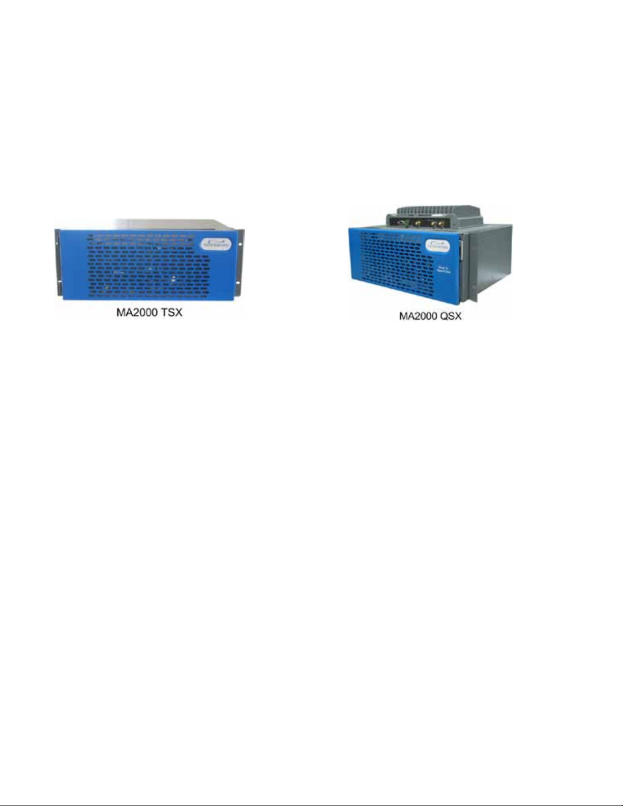
MA2000 Tri-Service Package (MA2000 TSX)
installable remote-end enclosures that provide carrier-grade indoor coverage for a number of services over a single,
broadband architecture.
TSX supports three services, while QSX supports four services, where TSX units that are already installed in the field can be
upgraded to support another service. A wide range of services are supported, including 2G, 3G, and 4G mobile voice and
data services, where the combination of services supported by each unit is model dependent.
The TSX and QSX Units are displayed below.
and MA2000 Quad-Service Package (MA2000 QSX) series are compact, easily
Figure 1-1. MA2000 TSX (left side) and MA2000 QSX (right side)
Corning Optical Communications User Manual I CMA-XXX-AEN I Page 7
Page 8

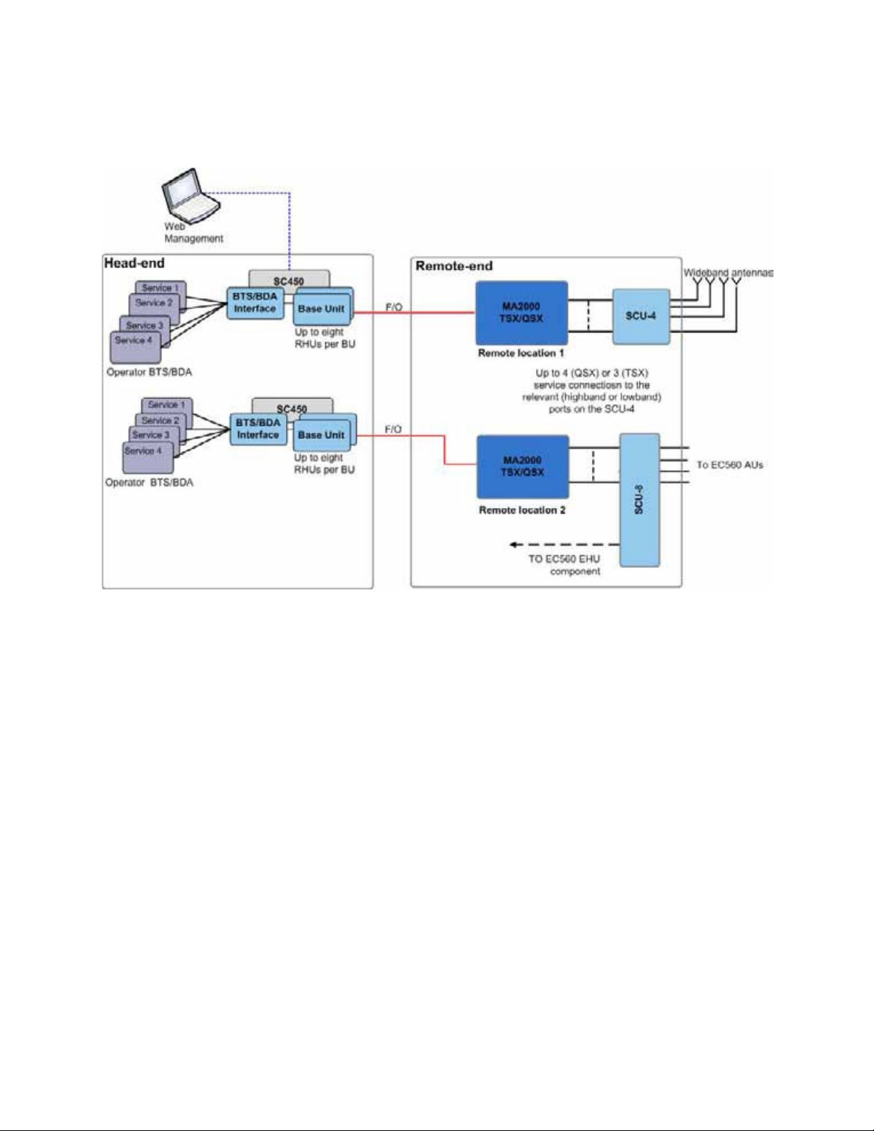
TSX and QSX units are securely located in the telecommunication closets at each remote location. The units receive the
head-end RF service signals via low-loss fiber, filter and reconvert the signals to RF. The RF services are combined and
distributed via a passive combiner (SCU-4) to the broadband antennas.
Figure 1-2. MobileAccesss2000 TSX/QSX System Architecture
1.1 Features and Capabilities
• Multi-operator platform - accommodates multiple operator requirements separately, yet cost-effectively across one
common infrastructure. Pre-assembled modular service packs improve neutral host ROI for the 1
as the 2
nd
and 3rd.
• Multi-service platform that accommodates virtually any mix of wireless services, eliminating the need for separate
cabled networks for each. Services include:
LTE, Paging, UMTS, DCS, WMTS, and more.
GSM, CELL, PCS, iDEN, LMR, SMR, Public Safety, AWS1/3, 700 MHz
• Modular design – enables seamless service upgrades with the addition of a conditioning card in the head-end and
self-contained service packs in IDF/Telco/IT closets at remote-ends.
• All active components are located in the communication closet/room
• Carrier grade management – Built-in signal grooming and an Element Management System (EMS) offer end-to-end
visibility and proactive alarming, ideal for large scale, multi-operator environments.
• Local and remote end-to-end monitoring and control through interface to SC-450 controller
• Conditioning and monitoring of input RF signals at the head-end through interface to MA-RIU
• Scalable Media and MIMO Upgrades - Additional services leverage the existing coaxial cabling and antenna grid
without disrupting work spaces or existing services. Fiber links extend a single capacity source across multiple
buildings in campus environments. Multi-MIMO upgrades are simple with modular elements.
st
carrier in, as well
Corning Optical Communications User Manual I CMA-XXX-AEN I Page 8
Page 9
2 MA2000 TSX/QSX Solution Architecture
The MobileAccess
Note: Third-party equipment is sold separately (i.e. cabling, antennas).
2000 TSX/QSX solution is comprised of the head-end and remote end elements described in this section.
Figure 2-1. MA2000 TSX/QSX Architecture Diagram
2.1.1 Head-End Equipment
At the head-end MobileAccess elements provide interface to the wireless service provider’s network, where the signals can
be conditioned through an active interface and transported over optic fiber to the remote end.
•
Radio Interface Unit (RIU): The RIU adjusts the RF signal source from a number of host base-transceiver stations
(BTS) or bi-directional amplifiers (BDA) and feeds the conditioned RF signals to the MobileAccess DAS coverage
systems
Base Unit (BU): The BU converts RF Downlink (DL) signals received from the RIU into an optical signal and
•
transports them to/from the MobileAccess
•
SC-450 System Controller: The system controller enables centralized remote management and control of all
MobileAccess
2000 elements at the site.
2000 TSX/QSX units at the remote site.
Corning Optical Communications User Manual I CMA-XXX-AEN I Page 9
Page 10

2.1.2 Remote-End Equipment
At the remote end, the MA2000 TSX/QSX units reconvert the optical signal to RF signals which are amplified, filtered and
distributed via a passive service combiner unit over the broadband antenna infrastructure. The output of multiple TSX/QSX
units can be combined to provide a full multi-service solution over a common fiber/coax antenna infrastructure.
• MA2000 TSX: The MA2000 TSX delivers coverage for three RF services
•
MA2000 QSX: The MA2000 QSX delivers coverage for four RF services (CELL, PCS, 700LTE and AWS). The subcomponents of the QSX are equivalent to that of the TSX with an additional AO.
Service Combiner Unit (SCU): A passive module that combines the services from the TSX or QSX and forwards the
•
combined signals to a single broadband antenna infrastructure. Two models are available, depending on the site
topology:
• SCU-4 –supports four (4) Low Band and four (4) High Band connections, used in site topologies where only
TSX/QSX services are distributed over the broadband antennas, mounted on top of the TSX/QSX enclosure.
SCU-8 - required for site topologies with EC560 solutions (interfaces between the TSX/QSX solution and the EC560
•
Antenna Units), includes eight (8) Low Band and eight (8) High Band connections, mounted in 19” rack.
an integral component of the EC560 solution and the installation procedure is described in the EC560 User Manual.
The SCU-8 is
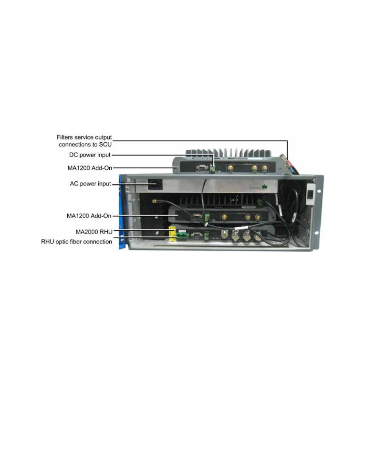
2.2 MA2000 TSX Interfaces
This section provides a description of the MA2000 TSX unit internal views and relevant connection interfaces. Refer to the
MA2000 User Manual
for detailed description of internal components (RHU and Add-On).
You will be required to connect:
• Optic fiber to
• The filter outputs to the Service Combiner Unit (SCU).
• Either AC or DC power
The TSX internal view is given below.
internal RHU
optic port
Figure 2-2. MA2000 TSX Open Cabinet View
3
Corning Optical Communications User Manual I CMA-XXX-AEN I Page 10
Page 11
2.3 MA2000 QSX Interfaces
This section provides a description of the MA2000 QSX unit internal views and relevant connection interfaces. Refer to the
MA2000 User Manual
You will be required to connect:
for detailed description of internal components (RHU and Add-On).
• Optic fiber to
• The filter outputs to the Service Combiner Unit (SCU).
• Either AC or DC power
internal RHU
optic ports
Figure 2-3. MA2000 QSX Open Cabinet View
Corning Optical Communications User Manual I CMA-XXX-AEN I Page 11
Page 12
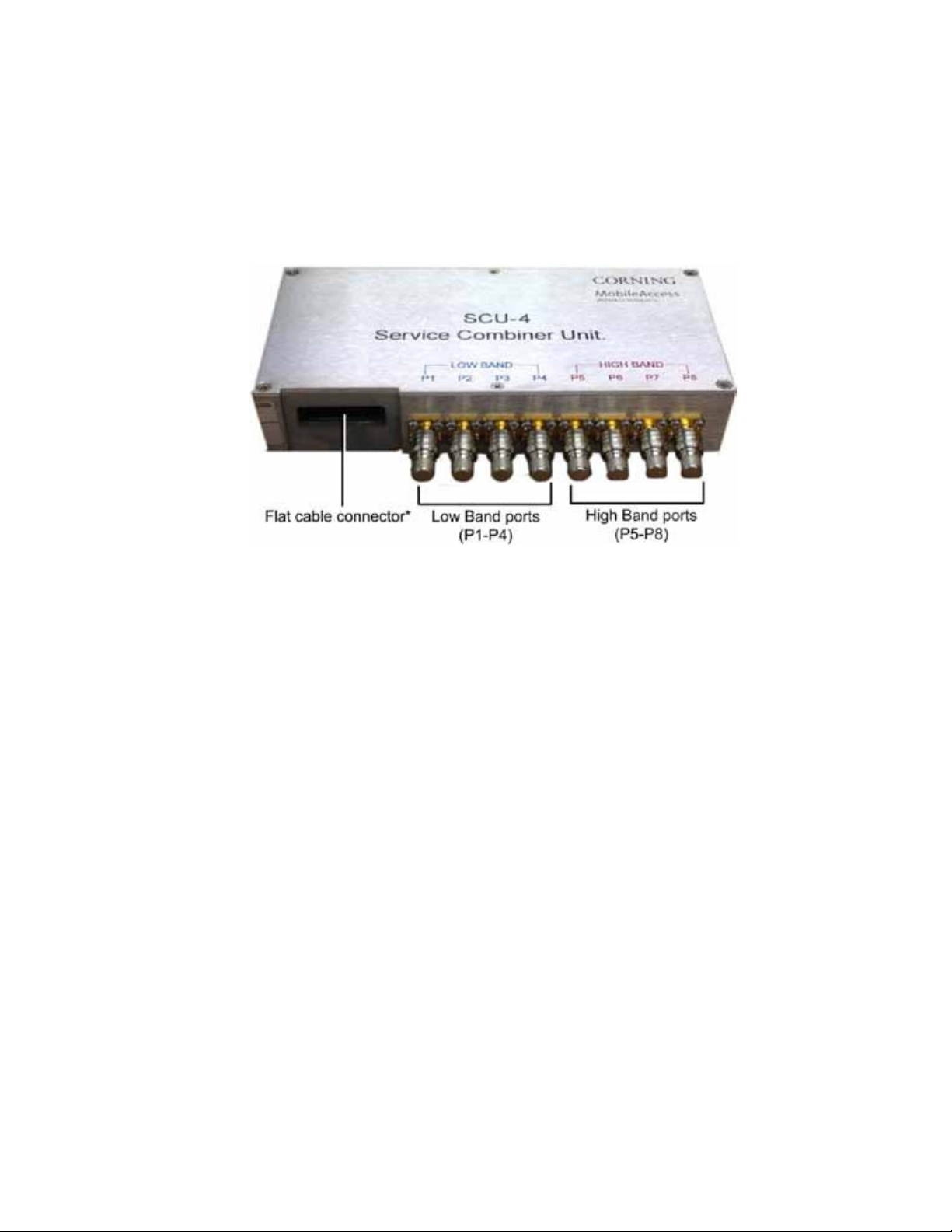
2.4 SCU-4 Interfaces
This section describes the SCU-4 int erfaces:
• Front Panel - consists of a total of eight QMA ports that support 4 low band (P1-P4) and 4 high band (P5-P8)
connections to the TSX/QSX solution(s).
• Rear Panel (not shown) – includes the RF antenna connectors that interface to the broadband antennas.
Figure 2-4. SCU-4 (Front Panel)
*Note: The flat cable connector is used for connecting the SCU-4 to an Antenna Monitoring Unit (AMU). See relevant AMU
Quick Installation Sheet for details.
3 TSX and QSX Physical Installation and Configuration
This section describes the installation procedure for the MA2000 TSX/QSX solution (same for both enclosure types) with an
SCU-4 unit.
Physical installation procedure steps:
1. Assemble SCU-4 on top of TSX/SCX enclosure. See section 0.
2. Connect between TSX/QSX filter outputs and SCU-4 High Band and Low Band ports. See section 3.2.
3. Mount the enclosure – three options:
• Rack mount (see section 3.3.1)
• Wall mount (brackets ordered separately). See section 3.3.2.
• Vertical mount (brackets ordered separately). See section 3.3.3.
4. Perform the following connections:
• Fiber optic cable to the MA2000 RHU optic port
• Power to the TSX/QSX power interface
• SCU RF antenna ports to the broadband antennas. See section 3.4.
Corning Optical Communications User Manual I CMA-XXX-AEN I Page 12
Page 13

Description
Qty.
Comment
4 Port Service Combiner Unit 1 -
3.1 Mounting SCU-4 on Top of TSX/QSX Enclosure
This section describes the SCU-4 mount ing for TSX and QSX.
Note: When using multiple 4 Port SCUs, a separate 1U rack shelf may need to be ordered separately to support a second
unit.
3.1.1 Mounting SCU-4 on TSX
3.1.1.1 Unpack Package Contents
Check your package content s to verify that the items in the packing list are included:
Note: A Phillips Head Screwdriver is required but is NOT included in the package.
MA2000 TSX Bracket
1 Bracket and accessories for mount ing the SCU dir ectly on
top of t he MA2000 TSX unit .
3.1.1.2 Plan Rack Installation
Note: This section is ONLY relevant for 19” rack mount installations.
1. Verify that the height of the rack can support all of the MA2000 TSX units being installed, as well as additional equipment,
SCU, AC or DC power, and space for the broadband coax connection. Also consider room for future expansions.
2. A max of three (3) MA2000 TSX units can be installed above or below the SCU or one (1) MA2000 QSX, depending on
the service configuration. However, it is recommended that the MA2000 TSX units are installed below the SCU.
3. To maintain a low center of gravity, ensure that heavier equipment is installed near the bottom of the rack and that the
rack is loaded from the bottom to the top.
Figure 3-1. Basic MA2000 TSX with SCU-4 Rack Installation Diagram
Corning Optical Communications User Manual I CMA-XXX-AEN I Page 13
Page 14

Description
Qty.
Comment
1
Bracket and accessories for mount ing the SCU dir ectly on
8
4 x Used for mount ing SCU-4 on bracket
3.1.1.3 Mount the SCU-4 on top of TSX Enclosure
NOTE: When mounting on SCU-4, be sure to mount on the top most MA2000 TSX unit.
1. Mount the SCU-4 unit on to the supplied bracket using the provided (4) screws.
2. Align the SCU-4 bracket holes (2 on each side of bracket) with the (4) top cover holes adjacent to the slot.
3. Mount the SCU-4 assembly with the SMA connectors facing the front of the Tri-Band Package (Facing the top cover slot).
Figure 3-2. SCU-4 Mounted on TSX Unit
3.1.2 Mounting SCU-4 on QSX
3.1.2.1 Unpack Package Contents
Check your package content s to verif y t hat the it ems in the packing list are included:
Note: A Phillips Head Screwdriver is required but is NOT included in the package.
MA2000 QSX Bracket
Screw s
top of the MA2000 QSX unit.
4 x Used for mount ing SCU-4 and br acket assembly on QSX
3.1.2.2 Plan Rack Installation
Note: This section is only relevant for 19-in rack mount installations.
1. Verify that the height of the rack can support the MA2000 QSX unit being installed, as well as additional equipment, SCU,
AC or DC power, and space for the broadband coax connection. Also consider room for future expansions.
2. One SCU-4 unit supports a single MA2000 QSX unit.
3. To maintain a low center of gravity, ensure that heavier equipment is installed near the bottom of the rack and that the
rack is loaded from the bottom to the top.
Corning Optical Communications User Manual I CMA-XXX-AEN I Page 14
Page 15

Figure 3-3. Basic MA2000 QSX with SCU-4 Rack Installation Diagram
3.1.2.3 Mount the SCU-4 on top of the QSX Enclosure
1. Mount the SCU-4 unit on to the supplied bracket using 4 appropriate screws (provided).
2. Align the SCU-4 bracket holes (2 on each side of bracket) with the (4) top cover holes adjacent to the slot.
3. Mount the SCU-4 assembly with the SMA connectors facing the front of the Quad-Band Package (facing the top cover
slot).
Figure 3-4. SCU-4 Mounted on QSX Unit
Corning Optical Communications User Manual I CMA-XXX-AEN I Page 15
Page 16

Service
Applicable MA2000 TSX Part
Number
MA2000 TSX Cable
SCU-4 Port (In order of
Preference)
700 MHz LTE
2000(M)-C85P19L70-x-TC-x
Low Band (BLUE)
Low Band Port 4
CELL
2000(M)-C85P19xx-x-TC
Low Band (BLUE)
Low Band Port 1, 4, or 2
SMR 900 (iDEN 900)
2000(M)-S80S90xx-x-TC
Low Band (BLUE)
Low Band Port 2
PCS
2000(M)-C85P19xxx-x-TC
High Band (RED)
High Band Port 5, 6, or 8
3.2 MA2000 TSX/QSX and SCU-4 Connections
The QMA cables on the MA2000 TSX/ QSX units are color coded such that the RED cables connect to the High Band port s of
the SCU and t he BLUE cables connect to t he Low Band ports of t he SCU.
Below are recommendat ions on specific Low Band/ High Band port s ( # 1-8) of the SCU to connect to based on t he MA2000
TSX/ QSX unit .
700/800 MHz Public
Safety
SMR 800 (iDEN 800) 2000(M)-S80S90xx-x-TC Low Band (BLUE) Low Band Port 3
AWS 2000(M)-C85P19xxx-x-TC High Band (RED) High Band Port 7
2000(M)-P71S80xx-x-TC Low Band (BLUE) Low Band Port 2 or 1
3.3 Mounting the TSX/QSX Enclosure
There are three types of mounting options available for the MA2000 TSX/QSX solutions:
• Rack Mount – enclosures are pre-assembled with 19” rack ears. See section 3.3.1.
• Wall Mount – wall mount brackets enable mounting the TSX/QSX enclosure parallel to the wall (brackets ordered
separately: AK-TC-ENC-WMT). See section 3.3.2.
• Vertical Mount – vertical mount brackets enable mounting the TSX/QSX enclosure in a vertical position on the wall
(brackets ordered separately: AK-TC-ENC-WMT-V – TSX). See section 3.3.3.
3.3.1 Rack Mount Installation
To mount the unit in a 19” rack
1. Insert each MA2000 TSX/QSX unit in the 19” rack. It is recommended to install the bottom unit first working your way to
the top, where the SCU mounted on top. Refer to Figure 1 in Step 1.
2. Open the doors of all the installed MA2000 TSX/QSX units. If needed, the doors can be removed from the enclosure by
lifting it from the hinge on the left.
Corning Optical Communications User Manual I CMA-XXX-AEN I Page 16
Page 17

Description
Qty.
Item
3.3.2 Wall Mount Installation
NOTE 1: The maximum weight that the MA2000 TSX/QSX wall mount bracket can hold is equivalent to a single MA2000 TSX
unit + a single Add-On RF module (~48lbs).
NOTE 2: When mounted to the wall, there will be approximately 60mm (2.36”) of space between the wall and the back of the
MA2000 TSX unit.
3.3.2.1 Package Contents
Check your package contents to verify that the items in the packing list are included.
Note: A Phillips Head Screwdriver is required but is NOT included in the package.
Wall Mount Brackets 2
8-Port Service Combiner Unit (SCU-8) Brackets
(Optional)
Screw: 4-40x1/4’, Flat Head Phillips 12
Screws: 6-32X5/16' Flat Head 100', Phillips 16
Below are the Front, Side and Top views of the Wall Mount Brackets. All dimensions are in millimeters (mm).
2
Figure 3-7. Side View of
Brackets
Figure 3-5. Top View of
Brackets
Figure
3-6. Front View of
Brackets
Corning Optical Communications User Manual I CMA-XXX-AEN I Page 17
Page 18

A
D
3.3.2.2 Wall Mount Procedure
To mount the MA2000 TSX/QSX unit on the wall
1. Mark and drill the installation holes on the wall using the bracket as a guide:
• Holes
• Holes
B & D are used for drilling 2 concrete anchors in to the wall.
A, C, and E are used for securing the brackets to the wall after hanging the assembly on the anchors.
B
C
E
Figure 3-8. Holes for Securing Bracket to Wall
2. Assemble the brackets to the MA2000 TSX/QSX enclosure as follows:
• Align the bracket installation holes with the eight (8) holes closest to the rear of the cabinet, as shown in Figure 3-9.
• Secure bracket to side of TSX/QSX cabinet using eight (8) 6-32X5/16' Flat Head 100', Phillips screws (supplied), as
shown in Figure 3-10.
Figure 3-9. Holes for Securing Wall Mount Bracket
Figure 3-10. Bracket Mounted on Side of
TSX cabinet
Corning Optical Communications User Manual I CMA-XXX-AEN I Page 18
Page 19

Description
Quantity
Item
Secure to
wall using
appropriate
3. Hang the assembly on the anchors and secure to wall using the (3) additional holes (screws not supplied).
Hang assembly on
anchors w ith t hese
screws
Figure 3-11. Bracket Mounted on Side of MA2000 TSX
holes
3.3.3 Vertical Mount installation
3.3.3.1 Package Contents
Verify t hat the items listed below are included in your kit .
Vertical Mount Bracket for MA2000 TSX/QSX
units
2
Screw,4-40X5/16',Flat-HD, 100', Philips, Nerosta 16
3.3.3.2 Vertical Mount Procedure
NOTE: The procedure is the same for both TSX and QSX enclosures. The QSX is shown here as an example.
To mount the MA2000 TSX/QSX unit vertically on the wall
1. Remove the pre-assembled rack ears from the sides of the MA2000 TSX/QSX cabinets.
NOTE: These can be saved for later use if required.
Rack ears (on each side)
Figure 3-12. MA2000 TSX/QSX Rack Ears
2. Assemble the vertical mount brackets:
Corning Optical Communications User Manual I CMA-XXX-AEN I Page 19
Page 20

MA2000 QSX
NOTE: You may want to mark the mounting holes on the wall (according to brackets) prior to assembly.
Using the provided screws (8 per bracket) secure a bracket to each side of the cabinet as shown in the following figures.
Vert ical Bracket
Figure 3-13. Location Assembly of Bracket on Enclosure
Corning Optical Communications User Manual I CMA-XXX-AEN I Page 20
Page 21

Assem bled
vertical mount
Assem bled vertical
mount bracket
Figure 3-14. Both Vertical Brackets Assembled on Enclosure Sides (Underside View)
3. Select appropriate location on wall for the MA2000 TSX/QSX unit.
NOTE: The vertical mount brackets include mounting holes for hanging on or screwing unit to wall.
Verify that :
• There is enough free space around the unit for ventilation
• Location enables opening the enclosure door to the side. Refer to Figure 3-15.
4. (If not already marked) Mark the mounting holes on the wall according to the bracket holes and dill appropriate holes.
5. Mount the MA2000 TSX/QSX unit on the wall as shown in the following figure.
Figure 3-15. Front View of MA2000 QSX Mounted Vertically on Wall
Corning Optical Communications User Manual I CMA-XXX-AEN I Page 21
Page 22

Local Power
MA2000 TSX
MA2000 QSX
3.4 MA2000 TSX/QSX Connections
After mounting the MA2000 TSX/QSX unit, perform the following connections:
1. Connect the fiber optic cable to the RHU subcomponent’s SC/APC connector for each MA2000 TSX/QSX unit. See
section 0 for Multimode Fiber (MMF) qualifications.
2. Connect the power source to the corresponding MA2000 TSX/QSX AC or DC connector.
MA2000 TSX and QSX power requirement s:
Local Power 100-240VAC (Integrated
AC/DC converter)
100-240VAC (Integrated AC/DC
converter)
Remote Power 25 to 48VDC 25 to 48VDC
Max. Power
77W 118W
Consumption
Note: The TSX/QSX is powered by an AC adaptor power supply (AC voltage is provided directly to the adaptor), so separate
grounding is not required for this installation. In compliance with UL and TUV safety (Standard: UL60950-1:2003).
3. If previously removed – replace enclosure door.
4. (Optional) - Place a label on the outside of each door identifying the supported services.
5. Connect the broadband coax to the rear N-Type connectors of the connected SCU via a jumper cable.
Corning Optical Communications User Manual I CMA-XXX-AEN I Page 22
Page 23

4 Upgrading MA2000 TSX with AWS Add-On
This section provides information on how to upgrade an existing MA2000 Tri-Service package (TSX) with an AWS AO (AddOn) unit, making it a QSX unit.
Note: This information can also be found in the MA TSX Upgrade Quick Installation Sheet provided with the upgrade kit.
Please note the following:
• This procedure requires
AO RF connections and replacing the cabinet top cover.
• SCU-4 cannot be assembled together with an AWS AO – on the same TSX unit. (If relevant, re-mount the SCU-4 on
another TSX unit or on the wall).
• The rack installation may need to be re-planned when mounting an AO unit on the TSX cabinet.
Upgrade procedure steps:
1. For rack installations – re-plan the rack installation if necessary.
2. Prepare the unit for upgrade – remove top cover and tray.
3. Change CELL-PCSH and LTE700 AO Unit Connections for Quad-Band.
4. Re-assemble top tray.
5. Assemble new top cover.
6. Mount AWS Add-On unit on enclosure.
7. Perform AWS Add-On RF connections.
8. Perform power connections
9. Tie and secure cables.
10. Mount the assembly.
11. Connect High-Band and Low-Band QMA cables to SCU.
12. Replace and/or close door of the unit.
removing the current TSX cabinet from the rack,
reconnecting the CELL-PCSH and LTE700
Corning Optical Communications User Manual I CMA-XXX-AEN I Page
23
Page 24

Kit
Item
Qty
Description
Item Image
4.1 Package Contents
Please verify that the kit includes the following items:
Note: A Phillips Head Screwdriver is required but is NOT included in the package.
AWS Add-On AWS Add-On Unit 1
MA2000 accessory
kit to upgrade TSX
tri-band to quad band
Top Cover Case for quad-band 1
Screws, 6/32 x 5/16', FLAT HD,
Philips
Screw, 8/32 X 1/2, PAN HD,
Philips
SPI D-TYPE/F 9 PIN Cable for
quad-band with diodes
Coax Cable CON. SMA-R.A to
CON.SMA-R.A L=60mm
16
4
1
2
Installed on the new
top cover.
Replaces the existing
top cover.
Used for securing top
cover to cabinet
Used for securing
AWS Add-on unit to
top cover
Used for AWS AddOn Control
connection
Used for LTE AO UL
and DL connections
Cable QMA to SMA R/A ,
RG233, L=1100MM-Low Band
1
Used for connecting
LTE700 AO Low
Band port
4.2 Plan Rack Installation
Verify that the height of the rack can support the MA2000 TSX with mounted Add-On unit on top.
Notes:
•
Each SCU-4 unit supports a single QSX.
•
If the TSX cabinet includes a 4 Port Service Combiner Unit (SCU-4), relocate the SCU-4 and mount it on either a
different TSX cabinet or on the wall.
Corning Optical Communications User Manual I CMA-XXX-AEN I Page 24
Page 25

Cut ALL cable
4.3 Prepare TSX Unit for Upgrade
1. Remove the TSX cabinet from the rack.
2. Remove top cover of the TSX cabinet. The tray with the power supply connections to the internal modules will be
uncovered.
3. Refer to Figure 4-1 - (temporarily) remove the tray:
• Cut cable ties
• Disconnect all power supply connectors
• Unscrew the top tray screws (9) securing the tray to the left (Figure 4-2
remove the top tray from the housing.
ties and
Tray
disconnect
ALL
connectors.
Figure 4-2. Side View of cabinet –
remove screws
)
and rear Figure 4-3) cabinet walls and
Figure 4-1. Top View of Tray Connections
Figure 4-3. Rear View of cabinet –
remove screws
Corning Optical Communications User Manual I CMA-XXX-AEN I Page 25
Page 26

UL and DL EXP.
RF cables
Low Band
Quad-band
LTE700 AO
CELL-PCSH RHU
4.4 Modify CELL-PCSH and LTE700 AO Unit Connections for Quad-Band
The following shows a block diagram of the CELL-PCSH/LTE700 AO/AWS AO connections.
1. Disconnect the UL and DL RF and SPI cables interconnecting the CELL-PCSH RHU and LTE700 AO units.
2. Refer to Figure 4-4 and perform the following connections:
• Connect the supplied QMA to SMA RF Low Band cable to the LTE700 rear panel
Low Band port.
• Connect the supplied UL and DL RF cables to the corresponding LTE700 AO UL and DL Expansion ports (on rear
panel).
Note: The UL and DL RF cables should be connected so that the labels face the top of the cabinet (towards the AWS
AO).
SPI cable
Figure 4-4. RHU and AO Units
Corning Optical Communications User Manual I CMA-XXX-AEN I Page 26
Page 27

4.5 Re-assemble Top Tray
1. Posit ion top tray (with fan and power supply) above the t ri-band assembly and secure w ith t he (9) screw s previously
removed in section 0 -
Corning Optical Communications User Manual I CMA-XXX-AEN I Page 27
Page 28

PS adapter
and bracket
Prepare TSX Unit for Upgrade.
2. Assemble the following components (shown in Figure 4-5):
• Power supply adapter and supporting bracket
• DC distribution card
• Base strip and hardware and filters
3. Reconnect power cable to DC board J3 connector.
4. Route the cables and tie them with the supplied nylon ties.
5. Screw the top tray screws (9) securing the tray to the left (Figure 4-2 and rear
Location of 9 screws securing
tray and cable ties
Top t ray
(
Figure 4-3) cabinet walls.
DC card
Filter
Corning Optical Communications User Manual I CMA-XXX-AEN I Page 28
Figure 4-5. Re-assembled Top Tray
Power cable connection
to DC board
Page 29

Routed quad-band
DB-9 SPI cable
Routed DC power
input cable
Coax jum per
cables
Openings toward
front
4.6 Assemble New Top Cover
1. Place the new top cover on the cabinet with the
2. Make sure that the DB-9 SPI cable, DC and coax cables are routed out through the corresponding openings in the top
cover.
3. Assemble the top cover using 16 6/32 x 5/16', FLAT HD, Philips screws (supplied).
two rectangular openings facing the front
.
Figure 4-6. TSX Top Cover Openings
4.7 Mount AWS Add-On Unit
1. Align the AO unit with the appropriate 4 holes on the top cover (circled in Figure 4-7).
2. Assemble AWS Add-On unit on to top cover using the four (4) 8/32 X 1/2, PAN HD, Philips screws (supplied) – two on
each side. See Figure 4-8.
Mounting screws
Figure 4-7. AO Unit Mounting Holes –
General Location
Corning Optical Communications User Manual I CMA-XXX-AEN I Page 29
Figure
4-8. AO Unit Mounting Holes –
General Location
Page 30

UL and DL
4.8 AWS Add-On RF Connections
Connect the rout ed cables from the CELL/ PCS RHU inside t he cabinet:
1. Interconnect DB-9 SPI cable between the RHU and the AO rear panel
From connector. Refer to Figure 4-9.
2. Perform the following RF connections (Refer to Figure 4-9):
• Interconnect the UL and DL SMA connections to the corresponding AO rear panel
• Connect the RF cable to the Add-On High Band port
High Band connections
connect ions
Figure 4-9: AWS AO Rear Panel Cable Connections
UL and DL ports.
DB9 SPI Cont r ol
connect ion
Corning Optical Communications User Manual I CMA-XXX-AEN I Page 30
Page 31

DC power
Term inal block
Adhesive cable
4.9 DC Power Connections
Refer to Figure 4-10 and per form the following connections:
• Connect the DC power cable to the AWS AO front panel DC connector.
• Connect the TSX cabinet terminal block (green connector) to j2 DC card.
Figure 4-10. Power Connections
Bundled
cables
4.10 Tie and Secure Cables
1. Referring to Figure 4-10 (previous page) - using a nylon cable, bundle and tie the RHU and Add-On cables (3) leading to
the SCU-4 unit and route them through the upper slot.
2. Referring to figure Figure 4-11 - using the Adhesive Cable Tie Mounts, secure the RF High Band connection cable to the
cover.
3. Close the TSX cabinet front door.
tie mount s
Figure 4-11. Secured High-Band connection
Corning Optical Communications User Manual I CMA-XXX-AEN I Page 31
Page 32

4.11 Install the Assembled MA2000 TSX with AWS AO in Communication Rack
1. Mount the assembled MA2000 TSX unit with AO in the 19” rack.
2. Open the door of the installed MA2000 TSX unit.
4.12 Connect QMA Cables to SCU
1. Route the QMA terminated cables through the cable routing slots. The tie-wraps can be disconnected to allow more cable
length. Leave room to route the fiber cable and power cable to the units.
filters are pre-connected as required for each service. Do not disconnect these cables.
2. Connect the BLUE QMA cables to the Low-band ports of the SCU.
3. Connect the RED QMA cables to the High-band ports of the SCU.
Note: All cables from RF service modules to
NOTE: Refer to section
3.2 for SCU-4 t MA2000 TSX/QSX connections.
4.13 Connect the Power Source
Connect the pow er source t o the MA2000 TSX AC/DC connector.
4.14 Replace and/or Close Door of the MA2000 TSX Unit
Recommended: Add a label on t he out side of t he door identifying t he addit ional service being support ed.
4.15 Configure Services
Refer to the System Controller User Manual and configure the services as required. (
required.)
System Cont roller v2. 0 or above is
Corning Optical Communications User Manual I CMA-XXX-AEN I Page 32
Page 33

Frequency Range
Services
Uplink
Downlink
RF Parameters Low Band
5 Appendix A: Specifications
5.1 RF Parameters
5.1.1 RF Frequency Range
CELL 824-849 869-894
iDEN 806-824 851-869
GSM 890-915 935-960
E-GSM 880-915 925-960
Telstra 850M 824-849 869-890
SMR 896-902 929-941
AWS3 1710-1778 2110-2180
DCS 1710-1785 1805-1880
PCS 1850-1910 1930-1990
G-PCS 1850-1915 1930-1995
UMTS 2100 1920-1980 2110-2170
5.1.2 Low Band
RU 20 0 0
Max output PWR per
antenna port
1 (comp) 16 14 10 12 14 10
2 carriers 13 11 7 9 11 7
4 carriers 10 8 4 6 8 4
8 carriers 7 5 1 3 5 1
12 carriers 5 3 -1 1 3 -1
Mean Gain(dB)* 16 7 14 7 10 7 12 7 14 7 10 7
Pin (dBm)* 0 0 0 0 0 0
Input IP3 (dBm)
AGC OFF Min
Input IP3 (dBm)
AGC ON Min
SFDR** (dB) 71 72 72 64 71 71
Max Intermod Distortion
(dBm)
Max Nf (dB) 20 20 20 20 20 20
TDMA/ CDMA/ WCDMA
CELL
DL UL DL UL DL U L DL U L DL UL DL UL
-5 -5 -5 -5 -5 -5
5 5 5 5 5 5
-13 -13 -13 -36 -13 -13
SMR
800
iDEN 8 00
Sprint
GSM/
E-GSM
SMR
900
I DEN 9 0 0
Sprint
Gain Flatn. (dB)
Corning Optical Communications User Manual I CMA-XXX-AEN I Page
33
±
2.0
Page 34

RF Parameters High Band
DL
UL
DL
UL
DL
UL
Max output PWR
per Antenna Port
1 (comp)
2 carriers
4 carriers
8 carriers
12 carriers
Mean Gain(dB)*
Pin (dBm)*
Input IP3 (dBm)
AGC OFF Min
Input IP3 (dBm)
AGC ON Min
SFDR** (dB)
Max Intermod Distortion (dBm)
Max Nf (dB)
Gain Flatn. (dB)
5.1.3 High Band
RU 2 00 0
DCS PCS CDM A/ WCDMA PCS GSM/ TDMA
14 14 16
11 11 13
8 9 10
5 6 7
3 4 5
14 3 14 3 14 3
0 0 2
-6 -6 -6
3 3 3
64 66 64
-30 -13 -13
20 20 20
*Factory set mean gain BU-RHU without RIU. May be field adjusted using system controller.
** SFDR for CDMA services is calculated in 100Kb/sec
± 2.0
Corning Optical Communications User Manual I CMA-XXX-AEN I Page 34
Page 35

MA1200 Add-on
LTE
700 MHz
G-PCS CDMA/WCDMA
G-PCS GSM/TDMA
UMTS*** and AWS3
CDMA/WCDMA
DL
UL
DL
UL
DL
UL
DL
UL
Max output PWR
per Antenna Port
1 (comp)
2 carriers
4 carriers
8 carriers
12 carriers
Mean Gain(dB)*
Pin (dBm)*
Input IP3 (dBm)
AGC OFF Min
Input IP3 (dBm)
AGC ON Min
SFDR** (dB)
Max Intermod
Distortion (dBm)
Max NF (dB)
Gain Flatn. (dB)
5.1.4 RF Parameters MA1200 Add-on
21 20 21 21
18 17 18 18
15 14 15 15
11 12 12
9 10 10
21 20 3 20 3 21 3
0 0 1 0
-10
-7 -7 -7
3 3
55 66 64 66 70
-13 -13 ***
20 20 20 20
4
+/-1.0
*Factory set mean gain BU-RHU without RIU. May be field adjusted using system controller.
* * SFDR for CDMA services is calculat ed in 100Kb/ sec
*** UMTS Compiles with 3GPP TS 25.106 V5.0.0 (2002-03) Table 9.4 spectrum emission mask
±
2.0
Corning Optical Communications User Manual I CMA-XXX-AEN I Page 35
Page 36

Support ed Services
5.2 Fiber Optic Specifications
Optical output power <3.0mW
Max. Optical budget 2 dB for fiber + 1 dB for connectors (assumed) = 3 dB total
Optical loss per mated-pair
connectors
Optical Connector SC/APC
Fiber type 9/125 SM
Wavelength 1310±10nm
Maximum distance between
Base Unit and Remote Cabinet
0.5dB (max)
2Km
5.3 Absolute Maximum Rating
Total Input RF Power to BU 10dBm
Total Input RF Power to RU
Power Supply VDC 60VDC
20dBm out-of-band
-10dBm in-band
5.4 Temperature Specifications
Operating
Storage
0°C to +50°C (32°F to 122°F)
-20°C to 85°C (-4°F to 185°F)
5.5 Components Specifications
5.5.1 Tri-Service Package (TSX)
The TSX comes fully assembled with the RF service modules, applicable filters, and accessories. The specifications below
reflect this.
Three services per TSX (1 RHU + 1 AO). Refer to the TSX model
for specific services support.
Port s
Pow er
Physical Characteristics
To Service Combiner Unit: 50Ω QMA cables
Local Power: 100-240VAC (Integrated AC/DC converter)
Remote Power: 25 to 48VDC
Max Power Consumption: 77W
Mounting: 19” Rack Mount brackets pre-connected; Wall Mount brackets to be ordered
separately
Dimensions: 43.4cm x 36.9cm x 17.7cm (17.09” x 14.53” x 6.97”)
Weight: 19Kg (42 lbs)
Corning Optical Communications User Manual I CMA-XXX-AEN I Page 36
Page 37

Pow er
Physical Characteristics
Supported Services
High band (1710 MHz
Ports
To MA2000 TSX: 8 QMA 50Ω connectors
(Terminate if unused; 6
To Antennas: 4 N
Physical Characteristics
Dimensions: 16.6cm x 8.0cm x 3.5cm (6.5” x 3.15” x 1.38”)
Comes with bracket t
Supported Services
High band (1710 MHz - 2170 MHz) and low band (698 MHz – 960 MHz) RF services
Required supporting element of the EC560 Solution
Ports
To MA2000 TSX: 16 QMA 50Ω connectors
(Terminate if unused; 14
QMA 50Ω
terminations
provided.)
To Antennas: 8 N
(
To EHU: 8 QMA 50
(Terminations not required)
Physical Characteristics
Dimensions: 43.3cm x 4.4cm x 27.00c
Weight: 3Kg (6.6 lbs)
Comes with brackets that allow it to be mounted on 19” rack as well as on the wall
5.5.2 Quad-Service Package (QSX)
The QSX comes f ully assembled wit h the RF service m odules, applicable filters and accessories. The specificat ions below
reflect t his.
Support ed Services
Port s
CELL, PCS, 700LTE, and AWS1/3 (1 RHU + 2 AO).
To Service Combiner Unit: 50Ω QMA cables
Local Power: 100-240VAC (Integrated AC/DC converter)
Remote Power: 25 to 48VDC
Max Power Consumption: 118W
Mounting: 19” Rack Mount brackets pre-connected; Wall Mount brackets to be ordered
separately
Dimensions: Dimensions: 43.4cm x 36.9cm x 26.6cm (17.09” x 14.53” x 10.47”)
Weight: 22Kg (49 lbs)
5.5.3 4-Port Service Combiner Unit (SCU-4)
-Type 50Ω connectors
hat allows it to be mounted directly on top of a MA2000 TSX
- 2170 MHz) and low band (698 MHz – 960 MHz) RF services
QMA 50Ω terminations provided)
(Terminate if unused)
5.5.4 8-Port Service Combiner Unit (SCU-8)
-Type 50Ω connectors
Terminate if unused)
Ω connectors
m (17.04” x 1.72” x 10.63”)
Corning Optical Communications User Manual I CMA-XXX-AEN I Page 37
Page 38

5.6 Multimode Fiber Qualifications
50/125 or 62.5/125um complying with ANSI/TIA/EIA-568-B series, EN50173-1 or ISO/IEC 11801, may be used up to 300
meters in length assuming the following qualifications:
• Both the Base Unit and MobileAccess
2000 TSX/QSX must be multimode capable.
• All fiber in a given length of fiber must be of the same core diameter.
• All bulkhead adapters must be Single-mode SC/APC (Green) adapters.
• All terminations, cross connections, or patches must be direct fusion splice or MobileAccess specified patchcords
listed below.
900 Micron Patchcord for Splicing, 2 M et ers, 2 xSC/ APC
62.5/ 125/ 900 Diamond p/ n ENC/ 1045341 FiberNext p/ n OEM-629002- MAN
50/ 125/ 900 Diamond p/ n ENC/ 1045340 FiberNext p/ n OEM-509002- MAN
Zipcord Patchcord, 4 xSC/ APC, 5 0/ 1 2 5/ 9 00/ 2 000 / 450 0 Micron
1Meter Diamond p/ n ENC/ 1045342 FiberNext p/ n OEM-50ZI P1-MAN
3 Met er Diamond p/ n ENC/ 1045343 FiberNext p/ n OEM-50ZI P3-MAN
Zipcord Patchcord, 4 xSC/ APC, 6 2.5 / 12 5 / 90 0 / 20 00/ 4 500 M icron
1Meter Diamond p/ n ENC/ 1045344 FiberNext p/ n OEM-62ZI P1-MAN
3 Met er Diamond p/ n ENC/ 1045345 Fiber Next p/ n OEM-62ZI P3-MAN
5.7 Software Management
Each RHU and Add-On m odule are configured and managed individually. Refer to the System Controller User Manual and
configure the services as required. (
System Controller v2.0 or above is required.)
Corning Optical Communications User Manual I CMA-XXX-AEN I Page 38
Page 39

Service Supported
Part Number
Description
700/800 MHz Public
2000-P71S80A17-A-TC
MA2000 TSX tri-service 700/800 MHz Public Safety and
AWS.
CELL/PCS
2000-C85P19-A-TC
MA2000 TSX dual-service CELL/PCS.
across same infrastructure.
CELL/PCS/AWS
2000-C85P19A17-A-TC
MA2000 TSX tri-service CELL/PCS and AWS.
iDEN/SMR
2000-S80S90-A-TC
MA2000 TSX dual-service 800/900 MHz SMR. Supports 700
MHz LTE and 700/800 MHz Public Safety coexistence.
iDEN/SMR/PCS
2000-S80S90P19-A-TC
MA2000 TSX tri-service 800/900 MHz SMR and PCS.
6 Appendix B: Ordering Information
6.1 MA2000 TSX
700/800 MHz Public Safety 2000-P71S80-A-TC MA2000 TSX dual-service 700/800 MHz Public Safety.
2000M-P71S80-A-TC MA2000 TSX dual-service 700/800 MHz Public Safety with
MM fiber.
Safety/AWS
2000M-P71S80A17-A-TC MA2000 TSX tri-service 700/800 MHz Public Safety and
AWS with MMF.
2000M-C85P19-A-TC MA2000 TSX tri-service CELL/PCS with MMF.
CELL/PCS/700LTE 2000-C85P19L70-A-TC MA2000 TSX tri-service CELL/PCS and 700 MHz LTE.
- Additional filter (P/N 700LTE-PS-FILTER) ordered
separately. Required if 700/800 MHz Public Safety coexists
2000-C85P19L70-A-TC-F MA2000 TSX tri-service CELL/PCS and 700 MHz LTE with
filter to support 700/800 MHz Public Safety coexistence.
2000M-C85P19L70-A-TC MA2000 TSX tri-service CELL/PCS and 700 MHz LTE with
filter to support 700/800 MHz Public Safety coexistence with
MMF.
- Additional filter (P/N 700LTE-PS-FILTER) ordered
separately. Required if 700/800 MHz Public Safety coexists
across same infrastructure.
2000M-C85P19L70-A-TC-F MA2000 TSX tri-service CELL/PCS and 700 MHz LTE with
filter to support 700/800 MHz Public Safety coexistence with
filter to support 700/800 MHz Public Safety coexistence and
MMF.
2000M-C85P19A17-A-TC MA2000 TSX tri-service CELL/PCS and AWS with MMF.
2000M-S80S90-A-TC MA2000 TSX dual-service 800/900 MHz SMR with MMF.
Supports 700 MHz LTE and 700/800 MHz Public Safety
coexistence.
Corning Optical Communications User Manual I CMA-XXX-AEN I Page 39
Page 40

coexistence.
2000M-S80S90A17-A-TC
MA2000 TSX tri-service 800/900 MHz SMR and PCS with
Safety coexistence.
Service Supported
Part Number
Description
GSM/DCS/UMTS 2100
2000-G92D18U21-A-TC
MA2000 TSX tri-service GSM/DCS and UMTS 2100.
E-GSM/DCS/UMTS 2100
2000-G90D18U21-A-TC
MA2000 TSX tri-service E-GSM/DCS and UMTS 2100.
Service Supported
Part Number
Description
CELL/PCS/700LTE/AW S
2000-C85P19L70A17-A-TC
MA2000 QSX quad-service CELL/PCS, 700 MHz LTE and
across same infrastructure.
2000-C85P19L70A17-A-TCF
MA2000 QSX quad-service CELL/PCS, 700 MHz LTE and
2000M-C85P19L70A17-A-
MA2000 TSX tri-service CELL/PCS and 700 MHz LTE with
across same infrastructure.
2000M-C85P19L70A17-
MA2000 TSX tri-service CELL/PCS and 700 MHz LTE with
MMF.
Supports 700 MHz LTE and 700/800 MHz Public Safety
coexistence.
2000M-S80S90P19-A-TC MA2000 TSX tri-service 800/900 MHz SMR and PCS with
MMF. Supports 700 MHz LTE and 700/800 MHz Public
Safety coexistence.
iDEN/SMR/AWS
2000-S80S90A17-A-TC MA2000 TSX tri-service 800/900 MHz SMR and AWS.
6.2 MA2000 TSX – International
6.3 MA2000 QSX
Supports 700 MHz LTE and 700/800 MHz Public Safety
MMF. Supports 700 MHz LTE and 700/800 MHz Public
AWS.
- Additional filter (P/N 700LTE-PS-FILTER) ordered
separately. Required if 700/800 MHz Public Safety coexists
AWS with filter to support 700/800 MHz Public Safety
TC
ATCF
Corning Optical Communications User Manual I CMA-XXX-AEN I Page 40
coexistence.
filter to support 700/800 MHz Public Safety coexistence with
MMF.
- Additional filter (P/N 700LTE-PS-FILTER) ordered
separately. Required if 700/800 MHz Public Safety coexists
filter to support 700/800 MHz Public Safety coexistence with
filter to support 700/800 MHz Public Safety coexistence and
Page 41

Part Number
Description
and 4 High Band services input ports. To be used with the MA2000 TSX solution.
Part Number
Description
Part Number
Description
Corning Optical Communications LLC • PO Box 489 • Hickory, NC 28603-0489 USA
800-743-2675 • FAX: 828-325-5060 • International: +1-828-901-5000 • www.corning.com/opcomm
P/N 709C01XXX Rev A00
6.4 Service Combiner Unit
SCU-4 Service Combiner Unit supporting 4 Antenna output ports, 4 Low Band services input ports
SCU-8 Service Combiner Unit supporting 8 Antenna output ports, 8 Low Band services input ports
and 8 High Band services input ports. To be used with the MA2000 TSX solution.
6.5 Accessories
6.5.1 Brackets
AK-TC-ENC-WMT Accessory kit containing contents to mount the MA2000 TSX and QSX onto the wall.
6.5.2 Filters
700LTE-PS-FILTER
Cavity filter for the 700LTE Add-On when 700LTE service coexists with 700/800 Public
Safety service across the same set of coax. This filter is already included with the MA2000
TSX CELL/PCS/700LTE part numbers with a “-F” suffix.
Corning Optical Communications reserves the right to improve, enhance, and modify the features and specifications of Corning Optical Communications
products without prior notification. A complete listing of the trademarks of Corning Optical Communications is available at
www.corning.com/opcomm/trademarks. All other trademarks are the properties of their respective owners. Corning Optical Communications is ISO 9001
certified. © 2015, 2016 Corning Optical Communications. All rights reserved. CMA-XXX-AEN / August 2016
Corning Optical Communications User Manual I CMA-XXX-AEN I Page 41
 Loading...