

Page 1
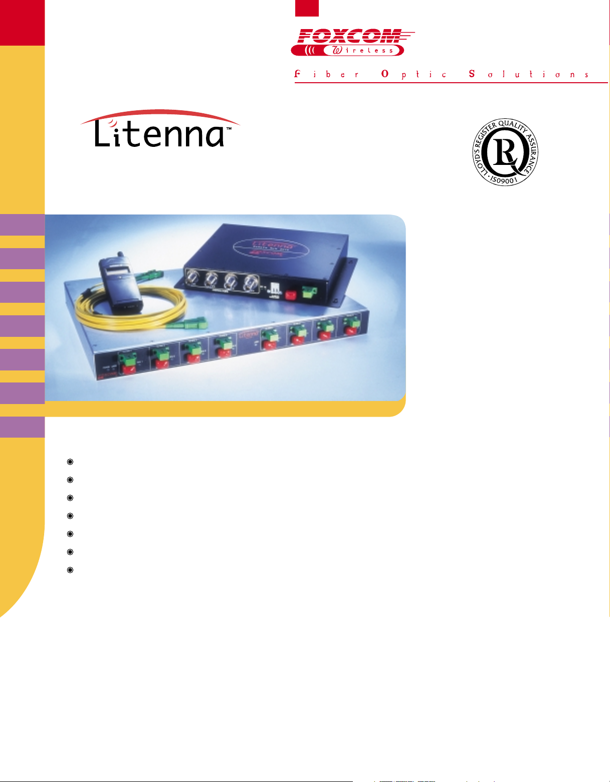
In-Building RF Distribution System
Compliant with all existing wireless voice and data services
Supports GPRS, EDGE, CDPD and WAP technologies
Easily upgradeable from single band to multi band and future services -3G
Single infrastructure for multiple services
and
Built-in alarms
Singlemode fiberoptic cables connect between the system units
Easy to design, install and maintain
The Litenna™, fiberoptic based distribution system, enables wireless service operators and
integrators to provide seamless cov erage and enhanced cellular capacity f or In-building applications .
Comprised of a Base Unit that connects up t o eigh t Remo te Hub Unit s (driving up to f our antennas
each), the fiberoptic technology based system is modular and expandable to a wide variety of
structure sizes and configurations. The Litenna supports wireless voice and data applications,
offering a cost-effective and flexible solution for coverage enhancement.
monitor
ing
for all
/ multiple ope
links
: TDMA, CDMA, GSM
rators
Page 2

Absolute Maximum Rating
Specifications
Total Input RF Power - No Damage (dBm)
Power Supply (VDC)
Operating Temperature (ºC)
Storage Temperature (ºC)
1. For extended temperature range (-20 to 60ºC) contact Foxcom Wireless.
1
Base Unit Remote Hub Unit
20 (Down Link)
60
0 to +50
-20 to +85
10 (Up Link)
60
0 to +50
-20 to +85
Fiber Optic Specifications
Optical Specifications
Optical output power (mW)
Max. Optical budget (dB)
Optical loss per mated pair connectors (dB)
Optical Connector
Fiber type
Wavelength (nm)
≤3.0
1.5
0.5 maximum
SC/APC
9/125 single mode
1310±10
General Specifications
Specifications Base Unit Remote Hub Unit
Power
Dimensions
RF Connector
Weight(Kg)
Other Specifications
Distance between BU and RHU (m)
DC power is supplied via composite cable @19AWG(1)
DC power is supplied via copper @ 12AWG(1)
MTBF (Hrs.) @ 25(ºC)
20-48VDC
10W max. Base Unit 8 ports
5W max. Base Unit 4 ports
19” x 1U Wallmount / Rackmount
N Type Female, Impedance 50 Ω
2.3
500 @ 48VDC
2000 @ 48VDC
366,855 for 1 Link (1 Bu+1 RHU)
20-48VDC - DC input
or: 27-48VDC - fed through composite cable
18 W max. Singleband
24 W max. Dualband
11”W x 8”L x 2”H
N Type Female, Impedance 50 Ω
1.2
(1) Distance increases with correlation to cable diameter.
For distance graeter than 2000m contact Foxcom Wireless.
Standards and Approvals
Europe
U.S.A
Canada
CE 0681 / ETS 300 609-4 (GSM 11.26), ETS 300 342-3, EN 60950 / EN 60825-2
FCC 47 CFT Part 22, 24, 90
IC
Page 3

Alarm Specifications
Base Unit Alarms
The Litenna™ Base Unit alarms are Dry Contacts and Open Collector types. The Dry Contacts opens when the alarm is active. The Open Collector will sink up to 30mA
under alarm condition. All alarms are connected to the Base Unit rear panel 25 pin D type connectors.
Alarm
Optical Link
Function
Indicates that the optical link between Base Unit and Remote Hub Unit are not functioning
LED Specifications
Base Unit LEDs
The Base Unit has three types of LEDs. One type indicates the power status. One type indicates that the lasers are functioning. One type indicates the status of link
operations between the Base Unit and the RHU-one LED for every RHU. All LEDs should be on when the unit is in operation.
LED Name
Channel 1..8
LED Function
Indicates that both directions of the optical link, between Base Unit and Remote Hub Unit,
is functioning - one LED for every RHU link.
Lasers 1..4
Lasers 5..8
DC
Indicates that laser circuitry for RHU 1-4 is functioning correctly.
Indicates that laser circuitry for RHU 5-8 is functioning correctly.
Indicates that the power is on.
Remote Hub Unit LEDs
On the Front Panel of the RHU ther e ar e two LEDs . Both LEDs should be on when the unit is in oper ation.
LED Name LED Function
Opt.
DC
Indicates that the Received Optical Power is functioning within specifications.
Indicates that the power is on.
Litenna™ Block Diagram
Litenna™ Base Unit
Down Link
RF In
(Sector 1)
RF In
(Sector 2 Opt.)
Up Link
RF Out
(Sector 1)
RF Out
(Sector 2 Opt.)
Fiberoptic
Tx #1
Fiberoptic
Tx #8
Fiberoptic
Rx #1
Fiberoptic
Rx #8
Litenna™ RHU #1
Fiberoptic
Rx #1
Fiberoptic
Tx #1
RF
RF
Litenna™ RHU #8
Fiberoptic
Rx #8
Fiberoptic
Tx #8
RF
RF
PA
PA
Diplexer
LNA
Diplexer
LNA
Page 4

©Sadna 5/2000
Foxcom Wireless Ltd.
Ofek One Center - Building B
Northern Industrial Zone
Lod, Israel 71293
Tel: +972-8-918-3888
Fax: +972-8-918-3844
E-mail: sales@foxcomwireless.com
Foxcom Wireless Inc.
8150 Leesburg Pike
Suite 600
Vienna, Virginia 22182
Tel: 703-848-0200
Fax: 703-848-0280
E-mail: salesna@foxcom wireless.com
Website: www.foxcomwireless.com
Mechanical Dimensions
19”
Base Unit
Base Unit Front Panel
Optical In/Out
12”
Base Unit Back Panel
RF In
Supported Services
Standard
AMPS/TDMA 800
LMR/iDEN 800
CDMA 800
SMR 900
GSM 900
Paging 900
GSM 1800
CDMA 1800
TDMA 1900
GSM 1900
CDMA 1900
Dual Band GSM 900/GSM 1800
Dual Band E-GSM 900/GSM 1800
Dual Band iDEN/LMR 800/PCS 1900
Daul Band SMR 900/PCS 1900
Dual Band Cellular 800/PCS 1900
Dual Band Paging 900/PCS 1900
Uplink
824-849
806-824
824-849
896-902
890-915
899-902
1710-1785
1710-1785
1850-1910
1850-1910
1850-1910
890-915/1710-1785
880-915/1710-1785
806-824/1850-1910
896-902/1850-1910
824-849/1850-1910
899-902/1850-1910
Available Accessories
Service
SC/APC Jumper
Local Power Supply
Remote Power supply Fully Redundant, Rackmount
Remote Power supply Fully Redundant, Rackmount
Remote Power supply Fully Redundant, Rackmount
Remote Power supply Wallmount
Specifications
1m
3m
15m
24W 110/220V
150W 110/220V
500W 110/220V
1000W 110/220V
200W 110/220V
For Indoor use only.
All specifications are subject to change without prior notice.
Order Code
SCAPC-DJ-1
SPAPC-DJ-3
SCAPC-DJ-15
LPS-24-1A
RPS-150-R-48
RPS-500-R-48
RPS-1000-R-48
RPS-200-N-48
1U
RF OutAlarm
Frequency Range
Downlink
869-894
851-869
869-894
935-941
935-960
928-941
1805-1880
1805-1880
1930-1990
1930-1990
1930-1990
935-960/1805-1880
925-960/1805-1880
851-869/1930-1990
935-941/1930-1990
869-894/1930-1990
928-941/1930-1990
Ordering Information
Remote Hub Unit
11”
Product
Single Band Family
9A110 = AMPS/TDMA 800
9A112 = LMR/iDEN 800
9A130 = CDMA 800
9A212 = SMR 900
9A220 = GSM 900
9A240 = Paging 900
9A320 = GSM 1800
9A330 = CDMA 1800
9A410 = TDMA 1900
9A420 = GSM 1900
9A430 = CDMA 1900
Dual Band Family
9B320 = Dual Band GSM 900/GSM 1800
9B322 = Dual Band E-GSM 900/GSM1800
9B412 = Dual Band iDEN/LMR 800/PCS1900
9B422 = Dual Band SMR 900/PCS1900
9B430 = Dual Band Cellular 800/PCS1900
9B440 = Dual Band Paging 900/PCS1900
Remote Hub Unit Front Panel
8”
Antenna Ports
* 1 antenna port Remote Hub Unit is also available.
BW
30 KHz
25 KHz
1.25MHz
25 KHz
200 KHz
200 KHz
1.25MHz
30 KHz
200 KHz
1.25MHz
9XXXX - XXX - XX
Part
R4U = RHU 4 Antenna Ports
R1U = RHU 1 Antenna Port
B4U = Base Unit Four Ports
B8U = Base Unit Eight Ports
Optical In/Out
2”
Reserved
© Foxcom Wireless 2000. Doc. No. 42-13-002-20-B
Page 5

Downlink
Link Specifications
Four Antenna ports RHU Spcifications
Nominal Output Power at Antenna Port
Per Carrier (dBm)
Composite (1 Carrier)
2 carriers
4 carriers
10 carriers
Nominal Gain (dB)
One Antenna Port RHU Spcifications
Nominal Output Power at Antenna Port
Per Carrier (dBm)
Composite (1 Carrier)
2 carriers
4 carriers
10 carriers
Nominal Gain (dB)
Common Spcifications
Nominal Input Power at Antenna Port
Per Carrier (dBm)
Composite (1 Carrier)
2 carriers
4 carriers
10 carriers
Gain Flatness (dB)
Over Band
Over Block
Max. Intermodulation Distortion (dBm)
Output 1dB Compression Point (dBm)
Spectral Regrowth (CDMA only)
800
14
10
14
18
14
12
18
-4
-6
±2.0
±1.5
-13
25
CDMA
1800
1900
14
14
10
10
8
–
–
0
–
10
18
14
12
14
-2
±2.5
±1.8
-13
25
8
8
–
–
10
18
14
12
–
–
14
4
4
0
0
-2
–
–
±2.5
±1.8
±2.0
±1.5
-13
25
GSM LMR/iDEN
900
1800
11
14
11
10
-2
-6
-36
25
8
5
1
7
8
–
4
1
±2.5
±1.8
11
8
5
1
7
14
11
8
–
10
4
1
-2
-6
-30
25
IS - 95 , J-STD - 008
1900
17
14
11
7
10
21
18
15
11
14
7
4
1
-3
±2.5
±1.8
-13
25
800
20
17
14
10
14
24
21
18
14
18
±2.0
±1.5
-13
25
SMR
Paging
900
900
20
20
17
17
14
14
10
10
14
14
24
24
21
21
18
18
14
14
18
18
-4
±2.0
±1.5
-13
25
6
6
3
3
0
0
-4
±2.0
±1.5
-13
25
6
3
0
-4
800
20
17
14
10
14
24
21
18
14
18
-4
±2.0
±1.5
-13
25
TDMA
6
3
0
1900
17
14
11
7
10
21
18
15
11
14
7
4
1
-3
±2.5
±1.8
-13
25
Uplink
Link Specifications
Four Antenna Ports RHU Spcifications
Max. NF (dB)
SFDR
One Antenna Ports RHU Spcifications
Max. NF (dB)
SFDR
Common Spcifications
Nominal Gain (dB)
Min. Input IP3 (dBm)
Output 1dB Compression Point (dBm)
Gain Flatness (dB)
Over Band
Over Block
CDMA GSM Paging
1800
17
62
15
63
4.0
-2
-7
900
16
67
14
69
4.0
-2
-7
±2.0
±1.5
17
67
15
69
4.0
-2
-7
±2.5
±1.8
800
16
62
14
63
4.0
-2
-7
±2.0
±1.5
1800
17
62
15
63
4.0
-2
-7
±2.5
±1.8
1900
±2.5
±1.8
LMR/iDEN SMR
1900
17
67
15
69
4.0
-2
-7
±2.5
±1.8
800
16
74
14
75
4.0
-2
-7
±2.0
±1.5
900
16
74
14
75
4.0
-2
-7
±2.0
±1.5
900
16
14
4.0
-2
-7
±2.0
±1.5
TDMA
1900
800
17
16
73
73
–
15
14
74
74
–
4.0
4.0
-2
-2
-7
-7
±2.5
±2.0
±1.8
±1.5
Page 6

Dual Band - RF SpecificationsSingle Band - RF Specifications
Downlink
Link Specifications
Four Antenna ports RHU Spcifications
Nominal Output Power at Antenna Port
Per Carrier Per Band (dBm)
Composite (1 Carrier)
2 carriers
4 carriers
10 carriers
Nominal Gain (dB)
One Antenna port RHU Spcifications
Nominal Output Power at Antenna Port
Per Carrier Per Band (dBm)
Composite (1 Carrier)
2 carriers
4 carriers
10 carriers
Nominal Gain (dB)
Common Spcifications
Nominal Input Power at Antenna Port
Per Carrier Per Band (dBm)
Composite (1 Carrier)
2 carriers
4 carriers
10 carriers
Gain Flatness (dB)
Over Band
Over Block
Max. Intermodulation Distortion (dBm)
Output 1dB Compression Point (dBm)
Spectral Regrowth (CDMA only)
800/1900
iDEN/LMR
20
17
14
10
14
24
21
18
14
18
6
3
0
-4
±2.0
±1.5
-13
25
PCS*
14 / 17
10 / 14
8 / 11
– / 7
10
18 / 21
14 / 18
12 / 15
– / 12
14
4 / 7
0 / 4
-2 / 1
– / -3
±2.5
±1.8
800/1900 900/1900 900/1900 900/1800
Cellular**
14 / 20
10 / 17
8 / 14
– / 10
14
18 / 24
14 / 21
12 / 18
– / 14
18
0 / 6
-4 / 3
-6 / 0
– / -4
±2.0
±1.5
-13
25
PCS*
14 / 17
10 / 14
8 / 11
– / 7
10
18 / 21
14 / 18
12 / 15
– / 12
14
4 / 7
0 / 4
-2 / 1
– / -3
±2.5
±1.8
SMR
20
17
14
10
14
24
21
18
14
18
±2.0
±1.5
IS - 95 , J-STD - 008
PCS*
14 / 17
10 / 14
8 / 11
18 / 21
14 / 18
12 / 15
– / 12
4 / 7
6
0 / 4
3
-2 / 1
0
– / -3
-4
±2.5
±1.8
-13
25
– / 7
10
14
Paging
20
17
14
10
14
24
21
18
14
18
6
3
0
-4
±2.0
±1.5
-13
25
PCS*
14 / 17
10 / 14
8 / 11
– / 7
10
18 / 21
14 / 18
12 / 15
– / 12
14
4 / 7
0 / 4
-2 / 1
– / -3
±2.5
±1.8
GSM/E-GSM
11
14
11
10
-2
±2.0
±1.5
-36
25
GSM
11
8
5
–
7
8
–
4
1
–
8
5
–
7
14
11
8
–
10
4
1
-2
–
±2.5
±1.8
-30
25
Uplink
800/1900
Link Specifications
Four Antenna Ports RHU Spcifica tions
Max. NF (dB)
SFDR
One Antenna Port RHU Spcifications
Max. NF (dB)
SFDR
Common Spcifications
Nominal Gain (dB)
Min. Input IP3 (dBm)
Output 1dB Compression Point (dBm)
Gain Flatness (dB)
Over Band
Over Block
* Specifications for PCS: CDMA / TDMA & GSM 1900.
** Specifications for Cellular: CDMA / TDMA 800.
iDEN/LMR
20
71
18
72
4.0
-2
-7
±2.0
±1.5
PCS*
20
71
18
72
4.0
-2
-7
±2.5
±1.8
800/1900 900/1900 900/1900 900/1800
Cellular**
20
71
18
72
4.0
-2
-7
±2.0
±1.5
PCS*
20
71
18
72
4.0
-2
-7
±2.5
±1.8
SMR
20
71
18
72
4.0
-2
-7
±2.0
±1.5
PCS*
±2.5
±1.8
20
71
18
72
4.0
Paging
4.0
-2
-7
±2.0
±1.5
20
18
-2
-7
PCS*
GSM/EGSM
20
–
–
71
18
72
4.0
-2
-7
±2.5
±1.8
4.0
±2.0
±1.5
20
65
18
67
GSM
20
65
18
67
4.0
-2
-7
-2
-7
±2.5
±1.8
 Loading...